ICOM orporated IC-F221S IC-F221S User Manual IC F111S F121S F211S F221S 1
ICOM Incorporated IC-F221S IC F111S F121S F211S F221S 1
UserManual.wiki
>
ICOM orporated
>
IC-F221S User Manual
>
Revised Users Manual
Contents
1.
Users Manual
2.
Revised Users Manual
Revised Users Manual
Navigation menu
Upload a User Manual
Namespaces
Wiki Guide
HTML
PDF
Info
Views
User Manual
Discussion / Help
Navigation
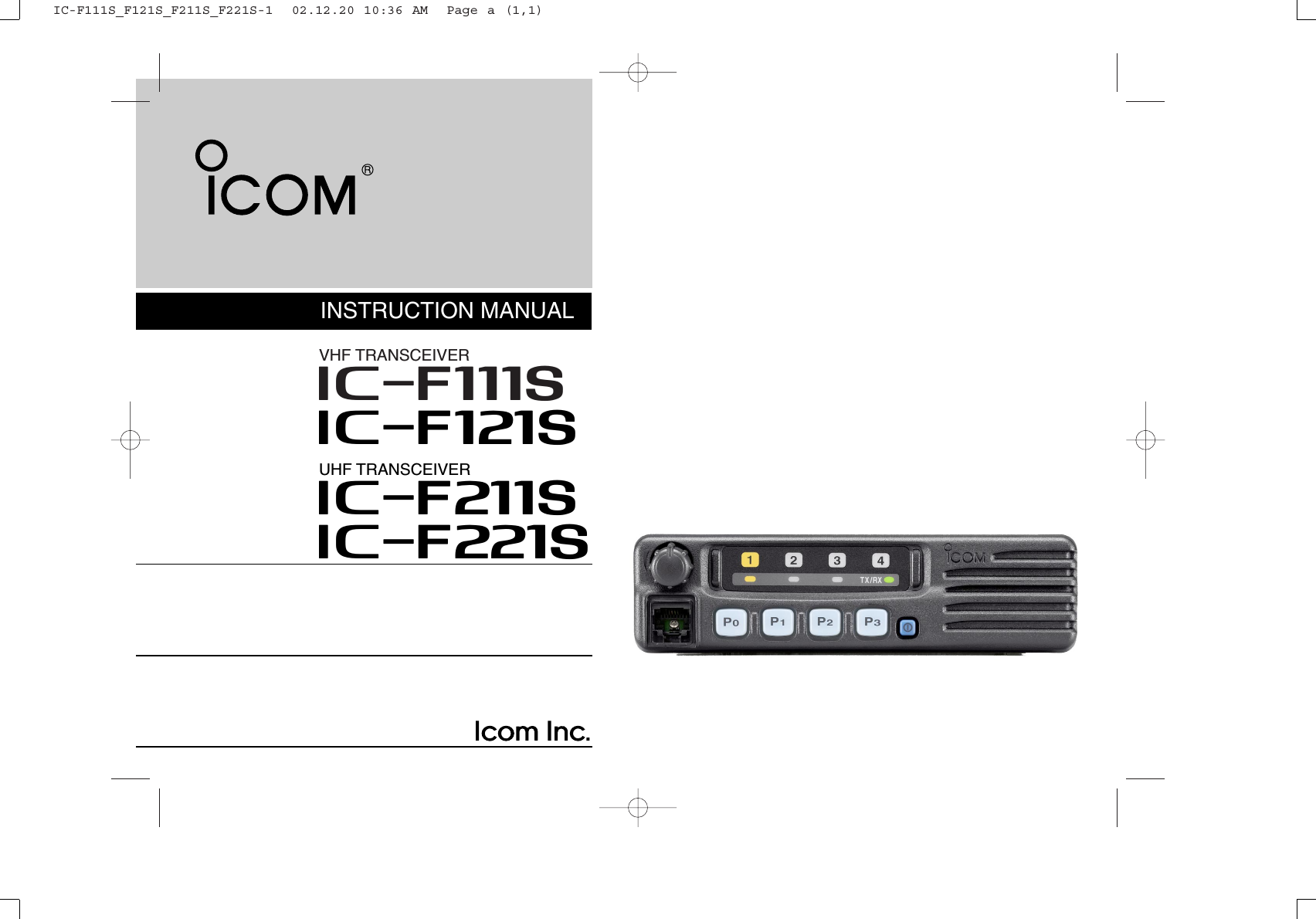
![11PANEL DESCRIPTIONTX/RX1234qwerFunction LED (p. 2)■Front panelqAF VOLUME CONTROL KNOB➥Rotate the knob to adjust the audio output level.• Minimum audio level is pre-programmed.wMICROPHONE CONNECTOR➥Connect the supplied microphone or optional DTMF micro-phone.NEVER connect non-specified microphones. The pinassignments may be different and the transceiver maybe damaged.eDEALER-PROGRAMMABLE KEYS [P0] to [P3]➥Desired functions can be programmed independently byyour Dealer.rPOWER SWITCH [POWER]➥Push to turn the power ON and OFF.• The following functions are available at power ON as options:- Automatic scan start- Password prompt- Set modeIC-F111S_F121S_F211S_F221S-1 02.12.20 10:36 AM Page 1 (1,1)](https://usermanual.wiki/ICOM-orporated/IC-F221S.Revised-Users-Manual/User-Guide-291397-Page-4.png)
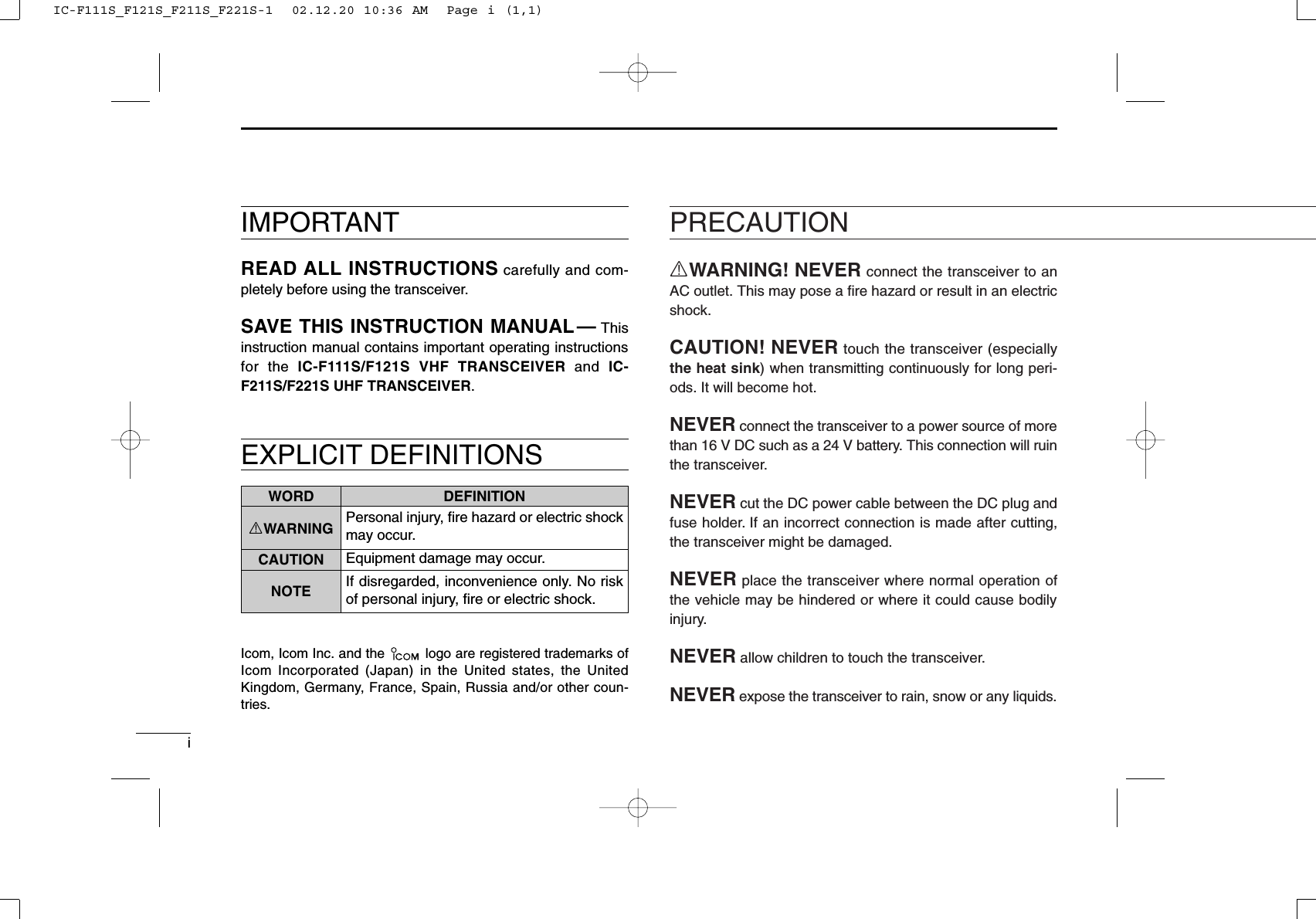
![31PANEL DESCRIPTION■Programmable function keysThe following functions can be assigned to [P0], [P1], [P2]and [P3] programmable function keys.Consult your Icom Dealer or System operator for details con-cerning your transceiver’s programming.In the following explanations, programmable function namesare bracketed. The specific switch used to activate the func-tion depends on programming.¡¡CH UP AND DOWN KEYSSelect an operating channel.¡¡BANK KEYSelect and determine a bank number.¡¡SCAN START/STOP KEYPush this key to start scanning; and push againto stop.NOTE: Place the microphone on hook to startscanning.Take the microphone off hook to stop scanning.CH UPCH DNBANK¡¡SCAN TAG KEYAdds or deletes the selected channel to the scangroup.¡¡PRIORITY CHANNEL KEYSPush these keys to select priority A or priority Bchannel, respectively.¡¡OPERATING CHANNEL KEYSSelect an operating channel directly.¡¡LOCK KEYPush this key for 1 sec. to lock all programmablekeys except the following:• [CALL](incl. [CAL A] and [CAL B]), [MONI]and [EMER]keys.PRI APRI BCH1CH2CH3CH4TAGSCAN ASCAN BLOCKIC-F111S_F121S_F211S_F221S-1 02.12.20 10:36 AM Page 3 (1,1)](https://usermanual.wiki/ICOM-orporated/IC-F221S.Revised-Users-Manual/User-Guide-291397-Page-6.png)
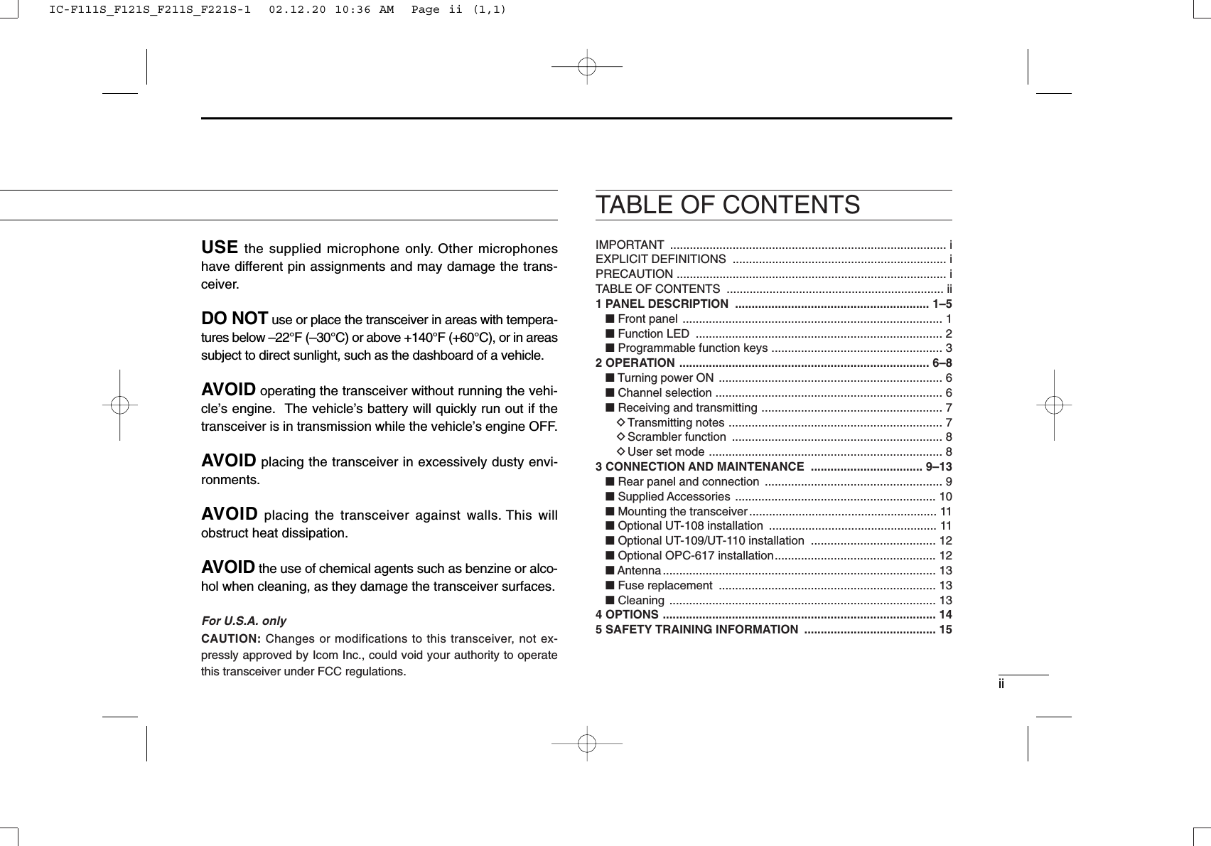
![41PANEL DESCRIPTION¡¡TALK AROUND KEYTurns the talk around function ON and OFF.• The talk around function equalizes the transmitfrequency to the receive frequency for mobile-to-mobile communication.¡¡WIDE/NARROW KEYPush this key to toggle the bandwidth betweenwide or narrow.¡¡DTMF AUTODIAL KEYPush this key to transmit a specified DTMF code.¡¡CALL KEYTransmit a 2-tone, 5-tone code.• Call transmission is necessary before you callanother station depending on your signaling sys-tem.• The [CAL A] and/or [CAL B] keys may be avail-able when your system employs selective‘Individual/Group’calls. Ask your Dealer whichcall is assigned to each key.¡¡MONITOR KEYActivates one of (or two of) the following functionson each channel independently:• Push and hold the key to unmute the channel (audiois emitted; ‘Audible’condition).• Push the key to toggle the mute and unmute condi-tions (toggles ‘Audible’and ‘Inaudible’).• Push the key to mute the channel (sets to ‘Inaudible’only).• Push the key to unmute the channel (sets to ‘Audible’only).• Push the key after communication is finished to send a‘reset code’.NOTE: The unmute condition (‘Audible’condi-tion) may automatically return to the mute con-dition (‘Inaudible‘ condition) after a specifiedperiod depending on the pre-setting.¡¡OUTPUT POWER SELECTION KEYSSelect the transmit output power temporarily, orpermanently, depending on the pre-setting.• Ask your Dealer or System Operator for the out-put power level for each selection.MONITAW/NDTMFH/LCALLCAL ACAL BIC-F111S_F121S_F211S_F221S-1 02.12.20 10:36 AM Page 4 (1,1)](https://usermanual.wiki/ICOM-orporated/IC-F221S.Revised-Users-Manual/User-Guide-291397-Page-7.png)
![51PANEL DESCRIPTION¡¡EMERGENCY KEYPush and hold the key to transmit an emergency call.• If you want to cancel the emergency call, pushand hold (or push) the key again before trans-mitting the call.• Depending on the pre-setting, the emergencycall is transmitted one time only, or repeatedly,until receiving a control code.¡¡Hook ScanSeveral functions are available for the hangerfunction when taking the microphone from itshanger (hanger-off) and/or returning it to thehanger (hanger-on).¡¡USER SET MODE KEYChanges the contents of the items in the User Setmode. Please refer to p. 8.•Push and hold this key for 1 sec. to enter setmode. Push this key again momentarily to selectthe desired item. Push [P2] and [P3] to set thedesired level/condition.Push and hold this key again to exit set mode.•User set mode also available via the ‘Power ONfunction’.¡¡SCRAMBLER KEY• Push and hold to turn the voice scrambler func-tion ON.• Push this key to turn the voice scrambler func-tion OFF.NOTE:• The optional UT-109 (#02) or UT-110 (#02)VOICE SCRAMBLER UNIT is required.– UT-109: Non-rolling type. 32 codes are available.– UT-110: Rolling type. Provides higher communi-cation security. 1020 (4 groups ×255) codes areavailable.• This transceiver requires version #02 ofthese units. Do not install version #01, asthey are not compatible.• Some PC board modifications are requiredwhen installing UT-109 and UT-110. Pleaserefer to ‘Optional UT-109/UT-110 installation’.(p.12)• Please contact your Dealer for details.EMERSCRMHOOKSETIC-F111S_F121S_F211S_F221S-1 02.12.20 10:36 AM Page 5 (1,1)](https://usermanual.wiki/ICOM-orporated/IC-F221S.Revised-Users-Manual/User-Guide-291397-Page-8.png)
![62OPERATION■Turning power ONqPush [ ] to turn the power ON.wIf the transceiver is programmed for a start up passcode,input the digit codes as directed by your Dealer.• The keys in the table below can be used for password input:• The transceiver detects numbers in the same block as identical.Therefore “01234” and “56789” are same.eWhen all channel indicator LEDs still blink after inputting 4digits, the input code number is incorrect. Turn the poweroff and start over in this case.■Channel selectionSeveral types of channel selection are available. The meth-ods may differ according to your system setup.NON-BANK TYPE:Push [CH UP]/[CH DN] to select the desired operating chan-nel, in sequence; or, push one of the [CH 1] to [CH 4] keys toselect a channel directly.BANK-TYPE: Push [BANK] to toggle between bank 1 and 2.AUTOMATIC SCAN TYPE:Channel setting is not necessary for this type. When turningthe power ON, the transceiver automatically starts scanning.Scanning stops when receiving a call or when taking themicrophone off hook.KEYNUMBER 0123456789IC-F111S_F121S_F211S_F221S-1 02.12.20 10:36 AM Page 6 (1,1)](https://usermanual.wiki/ICOM-orporated/IC-F221S.Revised-Users-Manual/User-Guide-291397-Page-9.png)
![72OPERATION■Receiving and transmittingRECEIVING:qPush [POWER] to turn the power ON.wPush [CH UP] or [CH DN] to select a channel.eWhen receiving a call, adjust the audio output level to acomfortable listening level.TRANSMITTING:rTake the microphone off hook.• The channel is busy when TX/RX indicator turns green.- According to the trasceiver’s setting;• 2-tone, 5-tone mute may be released. (The ‘audible’condition isselected)• A priority channel may be selected automatically.tWait for the channel to become clear.yPush the [CALL] key when initiating a call from your side.- According to the trasceiver’s setting;• Coded audio may be heard from the transceiver, then TX/RXindicator turns green.• This operation may not be necessary depending on your signal-ing system. Ask your Dealer.uWhile pushing and holding [PTT], speak into the micro-phone at your normal voice level.iRelease [PTT] to receive.IMPORTANT: To maximize the readability of your signal: (1) Pause briefly after pushing [PTT] (2) Hold the microphone 2 to 5 cm from your mouth, thenspeak into the microphone at a normal voice level.DTransmitting notes• Transmit inhibit functionThe transceiver has several inhibit functions which restricttransmission under the following conditions:• The channel is in mute condition.• Channel is busy.• A matched/non-matched CTCSS code is received.• The selected channel is a ‘receive only’channel.• Time-out timerAfter continuous transmission for a pre-programmed period,the time-out timer is activated causing the transceiver to stoptransmitting and automatically select receive.• Penalty timerOnce the time-out timer is activated, transmission is furtherinhibited for a period determined by the penalty timer.IC-F111S_F121S_F211S_F221S-1 02.12.20 10:36 AM Page 7 (1,1)](https://usermanual.wiki/ICOM-orporated/IC-F221S.Revised-Users-Manual/User-Guide-291397-Page-10.png)
![82OPERATIONDScrambler functionThe UT-109 (#02) or UT-110 (#02) optional voice scramblerunit provides high performance private communicationbetween stations with the same scrambler codes.qPush and hold [SCRM] to turn the scrambler function ON.wPush [SCRM] to turn the function OFF.DUser set modeUser set mode is accessed at power ON and allows you toset seldom-changed settings. In this case you can “cus-tomize” transceiver operation to suit your preferences andoperating style.Entering the user set mode:qWhile pushing and holding [P1] and [P2], push [POWER] toenter user set mode at power ON.wPush and hold [P0] to enter user set mode. Push [P0]again momentarily to select the item. The channel indicatorlights respectively to indicate the function is selected.Available set mode functions;•Backlight ( lights) : OFF, Dim, Auto or ON•Beep ( lights) : OFF or ON•SQL Level ( lights) : 0 to 255•AF Min level ( lights) : 0 to 255eThen push [P2] and [P3] to set the desired level/condition.rPush [POWER] (or push and hold [P0]) again to exit setmode.User set mode is also available via a programmable key.Please refer to p. 5 [SET] section.4321IC-F111S_F121S_F211S_F221S-1 02.12.20 10:36 AM Page 8 (1,1)](https://usermanual.wiki/ICOM-orporated/IC-F221S.Revised-Users-Manual/User-Guide-291397-Page-11.png)