ICOM orporated IC-F4G-3 Non-Broadcast Transmitter Held to Face User Manual corrected revised users manual final
ICOM Incorporated Non-Broadcast Transmitter Held to Face corrected revised users manual final
Contents
- 1. Users Manual
- 2. revised users manual with RF Safety Training
- 3. corrected revised users manual (final)
- 4. Revised Manual
corrected revised users manual (final)
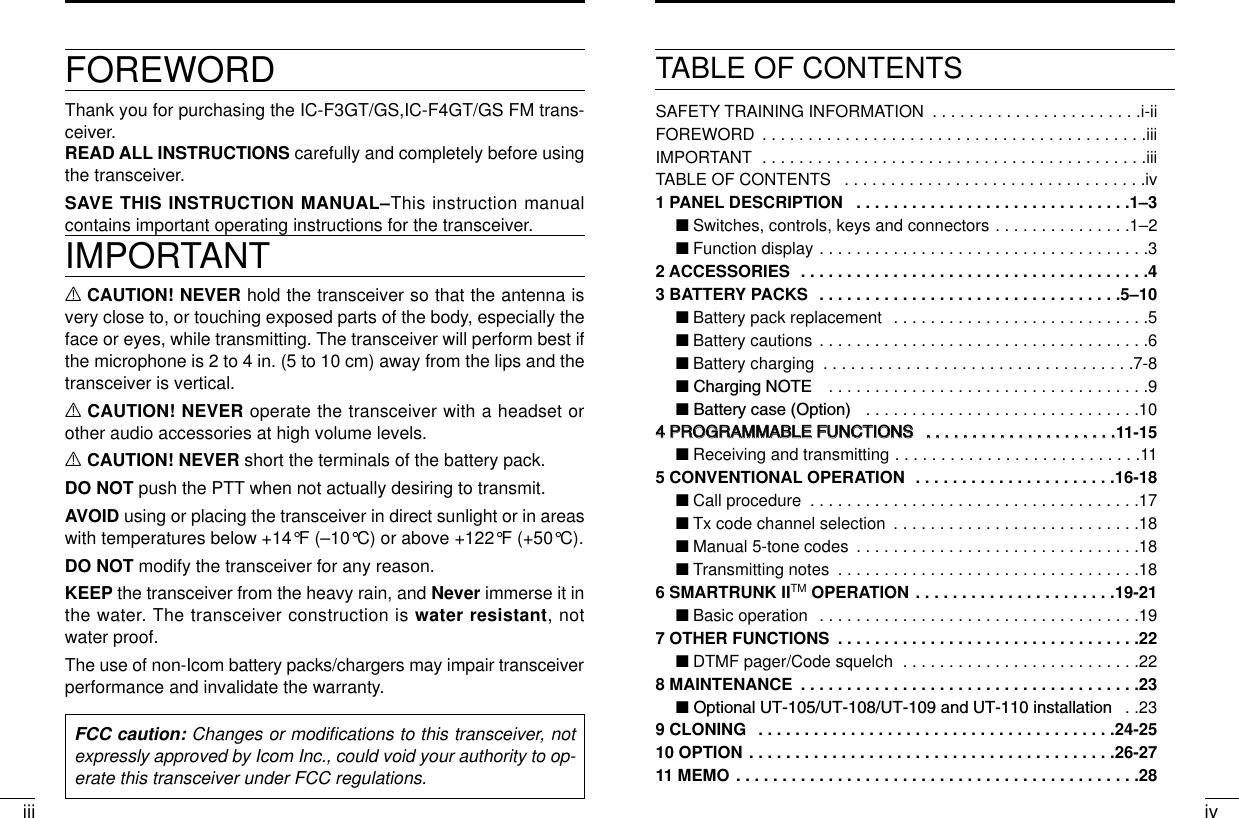
![1 21PANEL DESCRIPTIONPANEL DESCRIPTION1qVOLUME CONTROL [OFF/VOL]Turns power ON and adjusts the audio level.wDEALER-PROGRAMMABLE KEY [S1 (Red)]ePTT SWITCH [PTT]Push and hold to transmit; release to receive.rDEALER-PROGRAMMABLE KEY [S2(Black)]tUP/DOWN KEYS [YY]/[ZZ]• Push to select the operating channel.• Can be programmed as [ M]/[ # ]. (SmarTrunk mode only)yDEALER-PROGRAMMABLE KEYS [P0]/[P1]/[P2]/[P3]Can each be programmed for one of several functions by yourIcom Dealer.u10-KEY PAD (IC-F3GT/IC-F4GT only)Used to enter DTMF codes, the operating channel, etc.iANTENNA CONNECTORConnects the supplied antenna.o[SP]/[MIC] JACKConnect optional speaker-microphone.!0 FUNCTION DISPLAYDisplays the following information:• CH number.• 5-tone indication.• Low-battery indication.• DTMF numbers.• Low-power indication.• Skip-Ch indication.• Audible indication.NOTE: Above functions depend on pre-setting.‘‘Switches, controls, keys and connectors2345678901P0P1P2P3qwertyu!0ioSpeakerMicS1 (Red)S2 (Black)YYZZP0P1P2P3DDProgrammable key reference](https://usermanual.wiki/ICOM-orporated/IC-F4G-3.corrected-revised-users-manual-final/User-Guide-129134-Page-4.png)
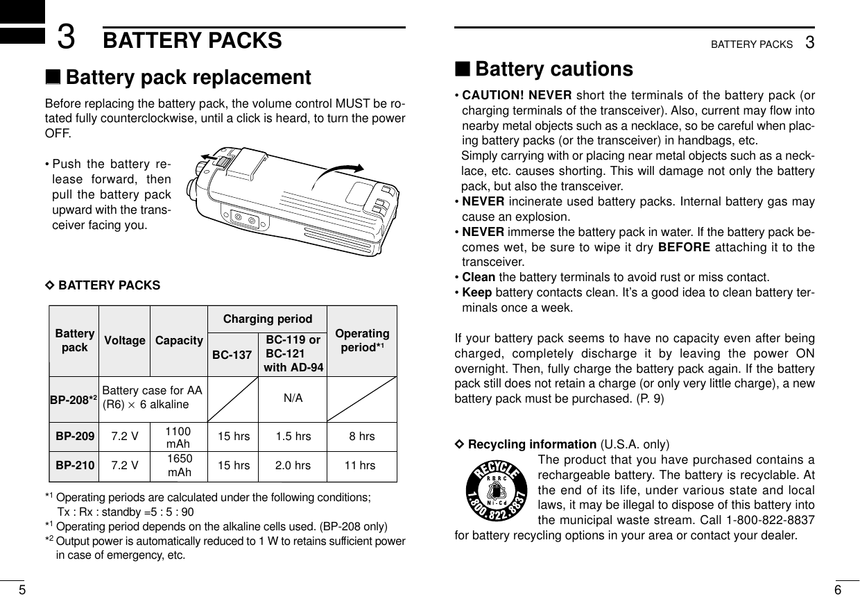
![2ACCESSORIESPANEL DESCRIPTION13 4‘‘Accessory attachmentDSupplied accessoriesThe transceiver comes supplied with the following accessories.qFlexible antennawBelt clipe2251 OPT sheet (See p. 26)DAntennaThe antenna screws onto the transceiver asillustrated right.Keep the jack cover attached when jacks arenot in use to avoid bad contacts. DBelt clip Attach the belt clip to the transceiver as illustrated below.qwe‘‘Function displayqTRANSMIT INDICATOR Appears during PTT on.wBUSY INDICATORAppears while receiving a signal or when the squelch is open.eLOW POWER INDICATOR (p. 12)Appears when low output power is selected.rSCRAMBLER INDICATORAppears while the scrambler function is operating.tKEY LOCK INDICATOR (p. 12)Appears during key lock function ON.yBELL INDICATIONAppears or blinks when the optional 2/5Tone call is received.uAUDIBLE INDICATORAppears when monitor function is turned ON. (CTCSS and DTCSmutes are released.)iLOW BATTERY INDICATOR [ ]-When appears, batterycapacity is low and transmitting is impossible.- When flashes, battery capacity is nearly exhausted.oALPHANUMERIC INDICATORoqw e r tyu iTo attach the belt-clip To release the belt-clip](https://usermanual.wiki/ICOM-orporated/IC-F4G-3.corrected-revised-users-manual-final/User-Guide-129134-Page-5.png)
![124PROGRAMMABLE FUNCTIONS114PROGRAMMABLE FUNCTIONS‘‘GeneralIn the following explanations, programmable function names arebracketed, the specific switch used to activate the function dependson programming.DDKEYPAD LOCK FUNCTIONThis function locks access to all programmable switches (exceptthe switch assigned for the lock function).:Push and hold the [LOCK] switch for 1 sec. to toggle the lock func-tion ON and OFF.• “”appears while the lock function is ON.• This function may be inhibited on some channels.DDPRIORITY CHANNELThis function is used to select a pre-programmed channel at thepush of a switch.Push the [PRIORITY] switch to select the priority channel.• “PRIO” appears briefly, then the priority channel is automaticallyselected.DDSCAN FUNCTIONThe scan function allows you to search a pre-programmed groupof channels for signals.Push the [SCAN] switch to start/stop scan.• Scan pauses on a channel when receiving a signal.• Depending on programming, a message may appear while scan-ning.• “Lockout SCAN” (pre-programmed list SCAN) or “Priority SCAN”can be pre-programmed.• When the “Power-save function” is activated, the transceiverchecks all pre-programmed channels then returns to the “Power-save function” again.DDHIGH/LOW POWER OUTPUTThis function selects high or low power for a channel.Push the [HIGH/LOW] switch to toggle between high and lowpower.• “LOW” appears when low output power is selected.DDSCRAMBLER FUNCTION (optional UT-109 #01* or UT-110 #01*is required.)This function provides higher communication security.UT-109: Non-rolling type. 32 code numbers are available.UT-110: Rolling type. 1020 (4 group ×255) code numbers are avail-able.Push the [SCRM] switch to toggle the function ON and OFF.NOTE: NEVER use #02 High AF level versions, as they are notcompatibleDDBEEP FUNCTIONThis function provides confirmation beep tones when pushingswitches.Push the [BEEP] switch to toggle the function ON and OFF.](https://usermanual.wiki/ICOM-orporated/IC-F4G-3.corrected-revised-users-manual-final/User-Guide-129134-Page-9.png)
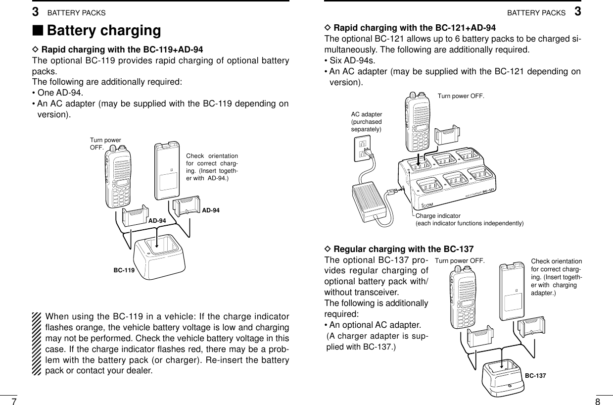
![144PROGRAMMABLE FUNCTIONS134PROGRAMMABLE FUNCTIONSDDMONITOR AUDIBLE FUNCTIONThe monitor function allows you to open the transceiver’s squelchmanually to check whether a channel is busy or not. The trans-ceiver has 2 conditions for receive standby:Audible condition:This condition mutes audio ONLY whenno carrier is present. You can receive (ormonitor) any signals on a channel.• Push and hold the [MONI/AUDI], switchto select the audible condition.Any audio mute functions are cancelledwhile pushing the [MONI/AUDI] switch.Inaudible condition:This condition mutes ALL signals exceptthose directed to you. Therefore youshould check a channel’s condition (busyor not) with the monitor function beforetransmitting.• Push the [MONI/AUDI] switch momen-tarily to select the inaudible condition.DDTALK AROUNDThe talk around function changes duplex channels to simplex chan-nels.• Duplex allows you to contact your base station, repeaters, etc.• Simplex allows you to contact other portable transceivers directly(portable-to-portable contact).Push the [TALK AROUND] switch one or more times to toggle thefunction ON and OFF.DDDTMF TRANSMISSIONThis function allows you to send a pre-programmed DTMF code tocontrol a repeater, open another transceiver’s squelch, etc.Manual transmission:Push desired digit keys in sequence while pushing [PTT].• Pushing [PTT] may not be necessary depending on programming.Automatic pre-programmed transmission:qPush the [DTMF] switch to select DTMF autodial mode, thenpush [Y] or [Z] to select the desired channel.wPush the [DTMF] switch once more to send a DTMF code.DD DTMF RE-DIAL FUNCTIONThis function allows you to transmit the last-used DTMF code at thepush of a key.Push the [DTMF RE-DIAL] switch momentarily to activate the func-tion.• The previously transmitted DTMF code is automatically transmit-ted.• If no code has been transmitted since turning the power ON, thisfunction does not activate.DDEMERGENCY FUNCTIONThe emergency function allows you to send your ID quickly andeasily to your Base Station, etc. in case of emergency.Push and hold the [EMERGENCY] switch for 1 sec. to activate theemergency function.• The transceiver selects a pre-programmed channel, then sendsan emergency signal to your Base Station.• The pre-programmed channel remains selected until a control sig-nal is received from the Base Station, or power is turned OFF.All signals arereceived2345678901P0P1P2P3Only signals containing the propertone arereceived2345678901P0P1P2P3](https://usermanual.wiki/ICOM-orporated/IC-F4G-3.corrected-revised-users-manual-final/User-Guide-129134-Page-10.png)
![165CONVENTIONAL OPERATION154PROGRAMMABLE FUNCTIONS• The emergency call is repeatedly transmitted at pre-programmedintervals.DDDISPLAY LIGHTINGThe function display has 3 backlight conditions.OFF : No backlight is available.AUTO : When any key is pushed, the backlight turns ON for 5sec. automatically.CONTINUOUS : Backlight turns ON continuously. DDSmarTrunk II™functionsThis transceiver provides SmarTrunk II™functions.(Optional UT-105 SmarTrunk II™Logic Board is required.)The optional UT-105 allows communication over conventionalchannels or SmarTrunk II™channels. Select a channel bank forSmarTrunk II™before trunking operation.To toggle SmarTrunk II™channels and conventional channels.Push the [Bank Up] switch one or more times.• Scanning starts when a channel bank for SmarTrunk II™is se-lected.• Contact your dealer for channel bank details.(See p.21 for more detailed operation.)‘‘Receiving and transmittingNOTE: Transmitting without an antenna may damage the trans-ceiver. See p.1 for antenna attachment.Turn power ON as described on p. 1.Receiving:qPush [YY]/[ZZ]to select a channel.wListen for a transmission and adjust [VOL] to a comfortable lis-tening level.• When no transmission is heard, push and hold monitor whileadjusting [VOL] (your transceiver may not be programmed withthe monitor function).The transceiver is now set to receive desired calls on the selectedchannel.Transmitting:Wait for the channel to become clear to avoid interference.eWhile pushing and holding [PTT], speak into the microphone at anormal voice level.• When a tone signalling system is used, the call procedure de-scribed at right may be necessary.rRelease [PTT] to return to receive.IMPORTANT: To maximize the readability of your transmitted sig-nal, pause a few sec. after pushing [PTT], hold the microphone 10to 15 cm from your mouth and speak at a normal voice level.](https://usermanual.wiki/ICOM-orporated/IC-F4G-3.corrected-revised-users-manual-final/User-Guide-129134-Page-11.png)
![175CONVENTIONAL OPERATION185CONVENTIONAL OPERATION‘‘Call procedureWhen your system employs tone signalling (excluding CTCSS andDTCS), the call procedure may be necessary prior to voice trans-mission. The tone signalling employed may be a selective callingsystem which allows you to call specific station(s) only and preventunwanted stations from contacting you.qSelect the desired Tx code channel or 5-tone code according toyour System Operator’s instructions.• This may not be necessary depending on programming.• Refer to the next page for selection.wPush the call switch (assigned to one of the dealer programma-ble switches: [P0], [P1], [P2], [P3], [S1] and [S2]).eAfter transmitting a 5-tone code, the remainder of your commu-nication can be carried out in the normal fashion.2345678901P0P1P2P32345678901P0P1P2P32345678901P0P1P2P32345678901P0P1P2P32345678901P0P1P2P32345678901P0P1P2P32345678901P0P1P2P32345678901P0P1P2P3Non-selective callingSelective calling‘‘Tx code channel selectionYour radio may be programmed for Tx code channel selection. Inthis case, you can choose a Tx code channel to be transmittedwhen using the call function (p. 7).Push the Tx code channel switch (assigned to one of the dealer-programmable switches) to activate the function, then enter digitsvia the keypad to select the desired Tx code channel.• The selected code channel (containing a pre-programmed 5-tonecode) is transmitted when using the call function.‘‘Manual 5-tone codesDepending on programming, you may be able to send 5-tone codesmanually.Push the Tx code switch to activate the function, then enter the de-sired transmit code (up to 7 digits) using the keypad.• Activate the call function to transmit the 5-tone code.• Blinking indicates keypad entry is acceptable.‘‘Transmitting notesDDTIME-OUT TIMERAfter continuous transmission for a pre-programmed period, thetime-out timer is activated, causing the transceiver to stop transmit-ting and automatically select receive.DDPENALTY TIMEROnce the time-out timer is activated, transmission is further inhibitedfor a period determined by the penalty timer.](https://usermanual.wiki/ICOM-orporated/IC-F4G-3.corrected-revised-users-manual-final/User-Guide-129134-Page-12.png)
![SmarTrunk IITM OPERATION206SmarTrunk IITM OPERATION196‘‘Basic operationThese features are enabled by your Dealer or System operator andmay not be available in your system. Contact your Dealer for de-tails.Push the [Bank Up] switch one or more times to select a channelbank for conventional channels or SmarTrunk II™channels.• Scanning starts when a channel bank for SmarTrunk II™is se-lected.DDPTT dispatch operation *1qPush [PTT] once (without dialling) to initiate a dispatch call.wBegin talking after you hear three beeps (one short, high-pitched, two very-short, low-pitched).eReceiving a dispatch call is indicated by the same three-beepsequence. • It is not necessary to push [M] to answer a dispatch call.DDSystem busy indication If all channels are busy, three low beeps sound after you initiate acall. Try the call again later.DDReceiving a subscriber-to-subscriber call *1When you hear ringing, push [M] to answer.• For a group call, you hear a short ring followed by two shortbeeps. You do not have to answer a group call to hear it over theair.DDReceiving a landline-to-subscriber call*1When you hear ringing, push [M] to answer.• For a group call, you hear a short ring followed by two shortbeeps. You do not have to answer a group call to hear it over theair.DDTerminating a call *1After completing a call, push [#] to disconnect (hang up).IMPORTANT: If one person in the conversation terminates a call, allparticipants will be cut off.DDLast number redial *1Push [M], [M] to automatically redial the last number called.• A high-pitched beep indicates that the number is accepted.*1: This function is available to for the IC-F3GS/IC-F4GS when the[Y]/[Z] keys are assigned the [M]/[ # ] key functions.DDTurbo SpeeDialTo automatically dial a commonly used number with one push:• Push one of the turbo SpeeDial keys.DDProgramming memory speed dial qPush and hold [M] until you hear a high-pitched beep.wEnter the memory location (0–9, A, B, C, D), the telephone orsubscriber number, then [1], [M] (or [3], [M] if for another systemsubscriber).• A high-pitched beep indicates successful programming.• Memories [A]–[D] are used for the Turbo SpeeDial.NOTE: This function is available for the IC-F3GT/IC-F4GT only.DDMemory speed-dialling *2To automatically dial a commonly used number from memory:• Push [M] followed by the memory location (0–9).](https://usermanual.wiki/ICOM-orporated/IC-F4G-3.corrected-revised-users-manual-final/User-Guide-129134-Page-13.png)
![227OTHER FUNCTIONS216SmarTrunk IITM OPERATIONDDClear channel alerting *1If all channels are busy, the transceiver automatically beginssearching for an open channel and beeps every ten seconds. Whentwo short beeps (low-pitched, then high-pitched) are heard, a chan-nel is available. Push [M], [M] immediately to redial the last num-ber.DDEmergency call *2Push [0], [M] to initiate an emergency call.• Contact your Dealer for details.DDPlacing a telephone call *2Enter the phone number followed by [1], [M].• A high-pitched beep indicates that the number is accepted.• When the called party answers, push the [PTT] switch to talk, andrelease it to listen.DDCalling another local system subscriber *2Enter the subscriber number followed by [3], [M].• A high-pitched beep indicates that the number is accepted.• You hear ringing, then two short beeps when the subscriber an-swers.• If the other subscriber is on another call or out of range, you heara fast busy signal and the call terminates automatically.*1: This function is available for the IC-F3GS/IC-F4GS when the[Y]/[Z] keys are assigned the [M]/[ # ] key functions.*2: This function is available for the IC-F3GT/GS,IC-F4GT/GSonly.Use the Turbo SpeeDial function instead.For additional operating instructions, contact your Dealer orSystem Operator.‘‘DTMF PAGER/CODE SQUELCHWhen you install optional the UT-108 DTMF DECODER UNIT intothe transceiver, DTMF pager function or code squelch function willbe available.DDDTMF pagerThis function uses DTMF tones for calling and can be used as a“common pager” to inform you that one of your group has calledeven if the operator is temporarily away from the transceiver.•When the connection code is received, a beep sounds, then “ ”flashes and shows the called stations code number.•Called stations code number are memorised automatically, andare easy to re-call with “ID-MR select function”.DDCode squelchThis conveniently eliminates unwanted audio and is useful in groupactivities or security related activities where unwanted output canbe a problem. The function is similar to a CTCSS tone squelch.In order to use the above functions, cloning is necessary via a PCusing the optional CS-F3G cloning software. Using this software,the transceiver’s model, individual RX Code CH, TX Code CH, Spe-cial Tone Link2 (must be ‘E’) on 5Tone screen, 5Tone SignalingForm on Memory-CH screen, Log, RX C-No, Key&Display, Com-mon AutoReset TimerB, and other settings related to operation canbe set. Refer to the HELP file that comes with the CS-F3GCLONING SOFTWARE for available settings.](https://usermanual.wiki/ICOM-orporated/IC-F4G-3.corrected-revised-users-manual-final/User-Guide-129134-Page-14.png)
![MAINTENANCE249CLONING238‘‘Optional UT-96/ UT-105/ UT-108/ UT-109/UT-110/ UT-111 and UT-113 installationYou can install one of the following optional signaling units in thetransceiver. UT-96 2TONE/5TONE UNIT, UT-105 SmarTrunk(TM) LogicBoard, UT-108 DTMF DECODER UNIT, UT-109/ UT-110 SCRAM-BLER UNIT, UT-111 TRUNKING BOARD or UT-113 MAN DOWNUNIT.qRemove the optional connecter access cover (named 2251 OPTsheet).•Insert a screwdriver into thehollow of the chassis, then liftand take away the cover.(The cover can not be usedagain.)wAttach the desired optional unit. Insert the connector tightly toavoid a bad contact.eRemove the paper backing of 2251 OPT sheet supplied as anaccessory.rAttach the new 2251 OPT sheet to the service window.tProgram the necessary infor-mation with the cloning soft-ware before operation.Please ask your dealer orsystem operator for details.werq‘‘CloningCloning allows you to quickly and easily transfer the programmedcontents from one transceiver to another transceiver; or data fromPC to a transceiver using the optional CS-F3G CLONING SOFT-WARE.DDTransceiver-to-transceiver cloningqConnect the optional OPC-474 CLONING CABLE with adapterplugs to the [SP] jack of the master and slave transceivers.•The master transceiver is used to send data to the slave trans-ceiver.wWhile pushing [P0] and [YY], turn the transceiver’s power on toenter cloning mode (For both the master transceiver and slavetransceiver).•“CLONE” appears and the transceiver enters the clone standbycondition.ePush [PTT] on the master transceiver.•“CLOUT” appears in the master transceiver’s display.•“CL IN” appears automatically in the slave transceiver’s display.•When cloning is finished, “CLONE” appears in the master trans-ceiver’s display.NOTE: DO NOT push the [PTT] on the slave transceiver duringcloning. This will cause a cloning error.rWhen cloning is finished, turn power off, then on again to returnto normal operation.•While pushing [P3] and [YY], turn the transceiver’s power on to enterCPU version check mode. CPU revision is displayed (“100CH” displayfor 100CH version only).NOTE: Transceiver-to-transceiver cloning can not be donebetween 40CH version and 100CH version, or CPU Rev.1.✻and Rev.2.0.](https://usermanual.wiki/ICOM-orporated/IC-F4G-3.corrected-revised-users-manual-final/User-Guide-129134-Page-15.png)