ICOM orporated IC-M1V VHF-FM Marine Hand Held Transceiver User Manual IC M1V
ICOM Incorporated VHF-FM Marine Hand Held Transceiver IC M1V
UserManual.wiki
>
ICOM orporated
>
IC-M1V User Manual
>
Manual
Contents
1.
Manual
2.
Revised page for manual
Manual
Navigation menu
Upload a User Manual
Namespaces
Wiki Guide
HTML
PDF
Info
Views
User Manual
Discussion / Help
Navigation

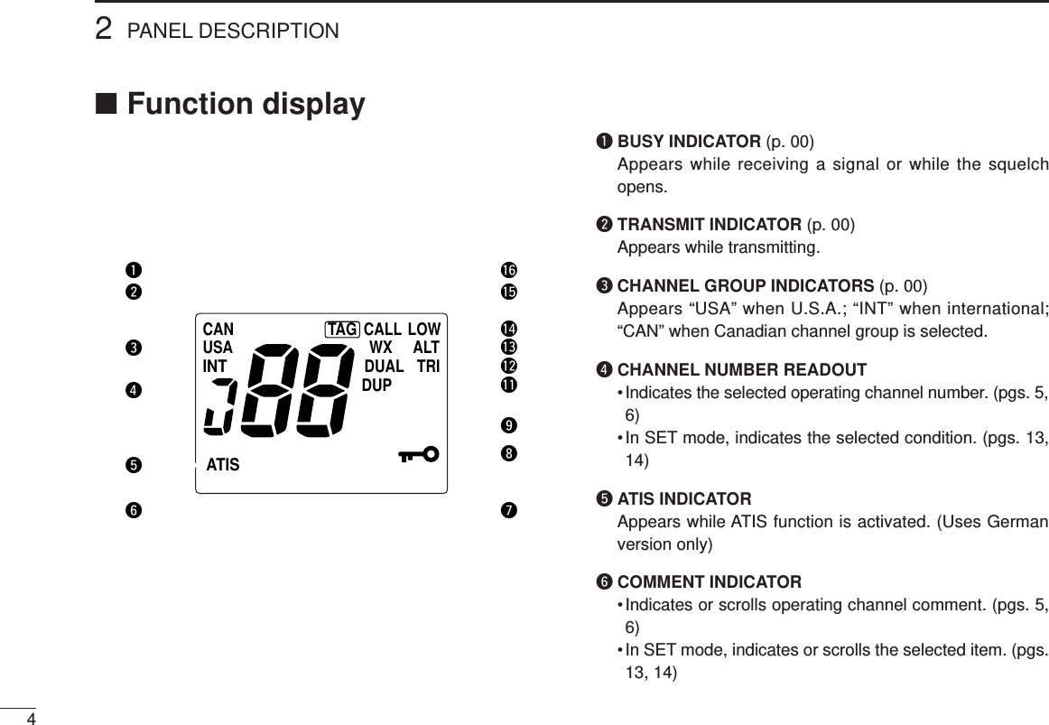
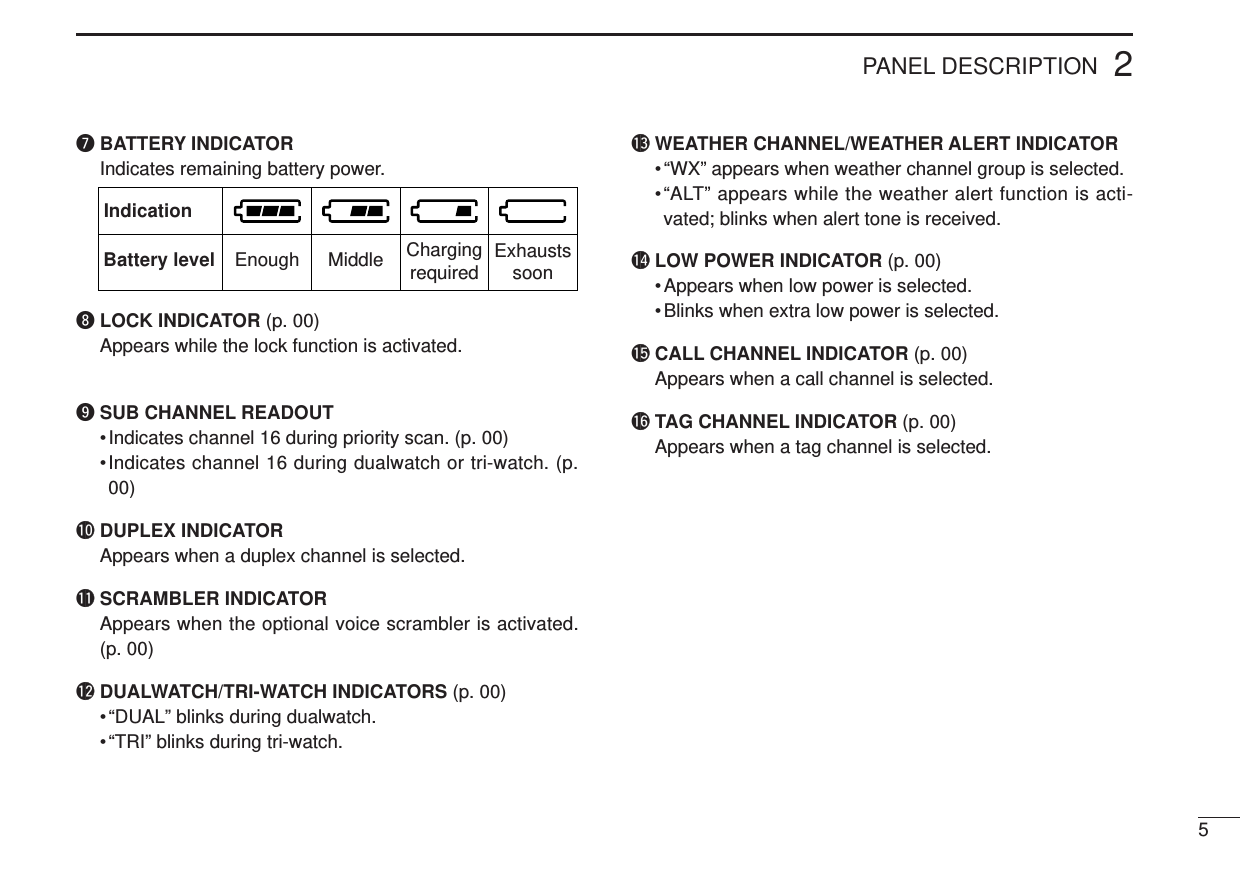
![■Panel description qANTENNA CONNECTORConnects the supplied antenna. (p. 00)wPTT SWITCH [PTT]Transmits during push and hold; receives during release.(p. 00)eMONITOR SWITCH [MONI]➥Opens the squelch and monitors the operating channelwhile being pushed.➥While turning power ON, enters the SET mode and pro-ceeds the SET mode contents when pushed. (p. 00)rBATTERY PACK RELEASE BUTTONTo remove the battery pack: Slides the battery release button upwards, then lift up thebattery pack.To attach the battery pack: Mate the notched ends of the transceiver and the batterypack, and click the battery pack into place.PANEL DESCRIPTION22](https://usermanual.wiki/ICOM-orporated/IC-M1V.Manual/User-Guide-71868-Page-6.png)
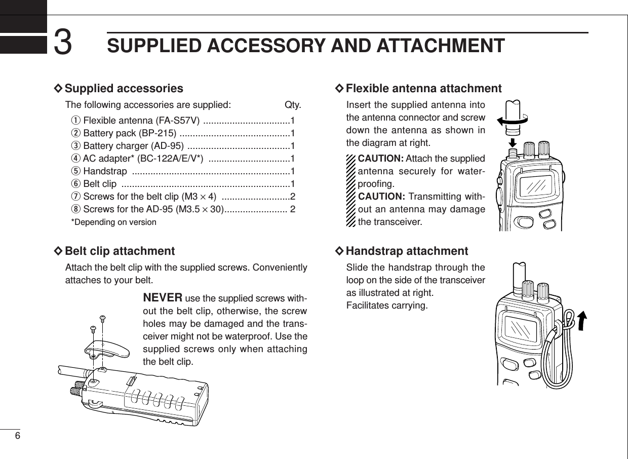
![tCHANNEL UP/DOWN SWITCHES [YY]/[ZZ]➥Push either switch to change the operating channel. (p.00)➥Push either switch to change the setting during setmode. (p. 00)➥Checks tag channels or changes scanning direction dur-ing scan. (p. 00)yCHANNEL 16 SWITCH [16•9]➥Selects channel 16 when pushed. (p. 00)➥Selects the call channel when pushed for 2 sec. (p. 00)➥Enters call channel write mode when the call channel isselected and this switch is pushed for 5 sec. (p. 00)uVOLUME CONTROL [VOL]Turns power ON and adjusts the audio level. (p. 00)iSQUELCH CONTROL [SQL]Sets the squelch threshold level. (p. 00)oCHANNEL/WEATHER CHANNEL SWITCH[CH/WX•U/I/C]➥Selects and toggles the regular channels and weatherchannel when pushed momentarily. (pgs. 00, 00)➥Selects one of 3 regular channels in sequence whenpushed for 2 sec. (p. 00)• International, U.S.A. and Canadian channels are avail-able for regular channels.!0 DUALWATCH/TRI-WATCH SWITCH [DW•TRI] (p. 00)➥Starts dualwatch when pushed momentarily.➥Starts tri-watch when pushed for 2 sec.➥Stops dualwatch/tri-watch when either is activated.➥Enters comment writing condition while pushing [MONI].(p. 00)!1 SCAN SWITCH [SCAN•TAG]➥Starts and stops normal or priority scan when tag chan-nels are programmed. (p. 12)➥Sets the displayed channel as a tag (scanned) channelor when pushed for 2 sec. (p. 12)➥Activates an optional voice scrambler function whilepushing [MONI]. (p. 8)➥Clears all tag channels in the selected regular channelwhen pushed and tuning power ON. (p. 12)!2 TRANSMIT POWER/LOCK SWITCH [H/L•LOCK]➥Toggles high and low power (1 W) when pushed. (p. 7)• Some channels are set to low power only.➥While pushing [MONI], push this key to select extra lowpower (500 mW). (p. 7)➥Toggles the lock function ON and OFF when pushed for2 sec. (p. 6)!3 SPEAKER-MICROPHONE CONNECTOR [SP MIC]Connects the optional speaker-microphone. (p. 00)PANEL DESCRIPTION32](https://usermanual.wiki/ICOM-orporated/IC-M1V.Manual/User-Guide-71868-Page-7.png)
![74BASIC OPERATION■Channel selection×Channel 16Channel 16 is the distress channel. It is used for establishinginitial contact with another station and for emergency com-munications. Channel 16 is automatically monitored duringboth dualwatch and tri-watch. While standing-by you have tomonitor channel 16.Channel 16 is instantly re-called when [16] is pushed.×Channel 9 (Call channels)Channel 9 is the pleasure call channel. Each regular channelgroup has separate call channels. In addition, each call chan-nel is monitored during tri-watch. The call channels can beprogrammed (p. ??) and are used to store your most oftenused channels in each group for quick recall.➥Push [16¥9] for 2 sec. to select the call channel; of the se-lected channel group.• “CALL” indicator and call channel number appear. • Each channel group may have an independent call channel afterchanging a call channel.USACALLTAGA channel comment“ ” is scrolled.USATAG](https://usermanual.wiki/ICOM-orporated/IC-M1V.Manual/User-Guide-71868-Page-11.png)
![84BASIC OPERATION×U.S.A., Canadian and international channelsThere are 57 international, 61 U.S.A. and 57 Canadian chan-nels. These channel groups may be specified for the operat-ing area.qPush [CH/WX] to select a regular channel.• If a weather channel appears, push [CH/WX] again.wPush [Y]/[Z] to select a channel.• “DUP” appears for duplex channels.eTo change the channel group, push [CH/WX•U/I/C] for2 sec.• U.S.A., Canadian and international channels can be selected insequence.×Weather channelsThere are 10 weather channels. Used for monitoring weatherchannels from the NOAA (National Oceanographic and At-mospheric Administration) broadcasts.The IC-M1V can detect a weather alert tone on the selectedweather channel while receiving the channel, during standbyon a regular channel or while scanning. See the “SET modeitems” on p. 14.➥Push [CH/WX] once or twice to select weather channels.Push for 1 sec. U.S.A. channelsCanadian channelsInternational channelsU/I/CU/I/CU/I/CCANDUPUSATAGINTCANUSAINTATISCALL LOWWX ALTDUALDUPTRITAGTXBUSYSCRMCANUSAINTATISCALL LOWWX ALTDUALDUPTRITAG](https://usermanual.wiki/ICOM-orporated/IC-M1V.Manual/User-Guide-71868-Page-12.png)
![4BASIC OPERATION9■Receiving and transmittingCAUTION: Transmitting without an antenna may dam-age the transceiver.qRotate [VOL] clockwise to turn power ON, then set to the10 o’clock position.• Turn [SQL] clockwise to mute any audio noise if necessary. Referto the previous page for details.wPush [Y]/[Z] to select the desired channel.• When receiving a signal, “BUSY” appears and audio is emittedfrom the speaker.• Further adjustment of [VOL] may be necessary at this point.• Use the optional voice scrambler function for privacy. (p. 8)ePush [H/L] to select the output power if necessary.• “LOW” appears when low power is selected.•Choose low power to conserve battery power, choose highpower for longer distance communications.• Some channels are for low power only.• An extra low power, Low 2, is available for short distance com-munications. Push [H/L] while pushing [MONI] in such case.rPush and hold [PTT] to transmit, then speak into the mi-crophone.• “TX” appears.• Channel 70 cannot be used for transmission (for GMDSS use).tRelease [PTT] to receive.IMPORTANT: To maximize the readability of your trans-mitted signal (voice), pause a few sec. after pushing [PTT],hold the microphone 10 to 15 cm (4 to 6 inches) from yourmouth and speak at a normal voice level.The transceiver has power save function to conserve thebattery power and cannot be turned OFF. The power savefunction activates automatically when no signal is receivedfor 5 sec.](https://usermanual.wiki/ICOM-orporated/IC-M1V.Manual/User-Guide-71868-Page-13.png)
![104BASIC OPERATION■Lock functionThis function electronically locks all keys and switches to pre-vent accidental frequency changes and function access.➥Push [H/L•LOCK] for 2 sec. to turn the lock function ONand OFF.• Only [PTT], [H/L] and [MONI] are functional.■Automatic backlightingThis function is convenient for nighttime operation. The auto-matic backlighting can be activated in SET mode. (p. 13)➥Push any key except for [PTT] to turn the backlighting ON.• The backlighting is automatically turned OFF 5 sec. after opera-tion.•Push [MONI] to turn the backlighting ON without changing theoperating condition.■Optional voice scrambleroperation×Activating the scramblerThe optional voice scrambler provides private communica-tions. In order to receive or send scrambled transmissionsyou must first activate the scrambler function. To activate thefunction, either an optional UT-98 or UT-122 is necessary. Askyour dealer for details.qSelect an operating channelexcept channel 16 or weatherchannels.wPush [SCN] while pushing andholding [MONI].• “SCRM” appears.eTo turn the scrambler functionOFF, repeat step w.• “SCRM” disappears.×Programming scramble codesThere are 128 codes (00 to 127) available with UT-98 or 32codes (00 to 31) available with UT-122 for programming. Inorder to understand one another, all transceivers in yourgroup must have the same scramble code, as well as thesame unit. See page ?? for scrambling code setting for de-tailsUSASCRMAppears when the voicescrambler function is in use.Appears when the lock function is in use.USA](https://usermanual.wiki/ICOM-orporated/IC-M1V.Manual/User-Guide-71868-Page-14.png)
![114BASIC OPERATION■Call channel programmingThe call channel key is used to select channel 9, however,you can program your most often-used channels in eachchannel group for quick recall.qPush [CH/WX•U/I/C] for 2 sec. sev-eral times to select the desiredchannel group (USA, INT, CAN) tobe programmed.wPush [16•9] for 2 sec. to select thecall channel of the selected chan-nel group.•“CALL” and call channel number ap-pear.ePush [16•9] again for 5 sec. (untillong beep changes to 2 shortbeeps) to enter call channel pro-gramming condition.•Call channel number and channelgroup to be programmed flashes.rPush [Y]/[Z] to select the desiredchannel.tPush [16•9] to program the dis-played channel as the call channel.• The call channel number and channelgroup stop flashing.USATAGUSATAGUSACALLTAGUSACALLTAGUSATAG CALLUSATAGUSACALLTAG](https://usermanual.wiki/ICOM-orporated/IC-M1V.Manual/User-Guide-71868-Page-15.png)
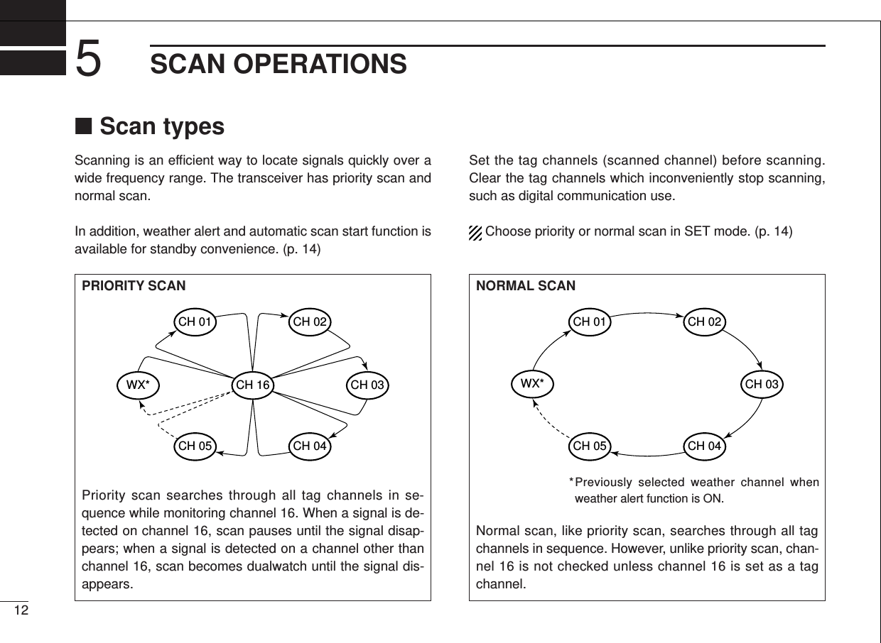
![■Setting tag channelsFor more efficient scanning, add desired channels as tagchannels or clear tag channels for unwanted channels.Channels set as non-tag channels will be skipped duringscanning. Tag channels can be assigned to each channelgroup (USA, INT, CAN) independently.qSelect the desired channel group (USA, INT, CAN) by push-ing [CH/WX•U/I/C] for 2 sec., if desired.wSelect the desired channel to set as a tag channel.ePush [SCN•TAG] for 2 sec., to set the displayed channelas a tag channel.• “TAG” appears in the function display.rTo cancel the tag channel setting, push [SCN•TAG] for 2sec.• “TAG” disappears.• Clearing all tag channels in the selected channel group➥Turn power ON while pushing and holding [SCN•TAG] toclear all tag channels in the channel group.■Starting a scanSet scan type, weather alert function, scan resume timer andauto scan function in advance using SET mode. (p. 14)qSelect the desired channel group (USA, CAN, INT) bypushing [CH/WX•U/I/C] for 2 sec., if desired.•When the weather alert function is in use, select the desiredweather channel with [CH/WX] and the channel selector.wPush [SCN] to start priority or normal scan.• The comment indicator indicates “SCAN”.• The sub channel readout indicates “16” during priority scan.•When a signal is received, scan pauses until the signal disap-pears or resumes after pausing 5 sec. according to SET modesetting. (Channel 16 is still monitored during priority scan.)•Push [Y]/[Z] to check the scanning tag channels, to changethe scanning direction or resume the scan manually.eTo stop the scan, push [SCN].• “SCAN” disappears.•Pushing [PTT], [16•9], [CH/WX] or [DW•TRI] also stops the scan.5SCAN OPERATION13Scan starts. Scan pauses when receiving a signal and audio is emitted.Push Push to stop the scan.USATAGUSADUPTAGUSATAGBUSYTA GTA G[Example]: Starting a normal scan.](https://usermanual.wiki/ICOM-orporated/IC-M1V.Manual/User-Guide-71868-Page-17.png)
![146DUAL WATCH/TRI-WATCH■DescriptionDualwatch monitors channel 16 while you are receiving an-other channel; tri-watch monitors channel 16 and the callchannel while receiving another channel.■OperationqSelect the desired operating channel.wPush [DW•TRI] momentarily to start dualwatch; push[DW•TRI] for 2 sec. to start tri-watch.• “DUAL” flashes during dualwatch; “TRI” flashes during tri-watch.• Beep tone sounds when a signal is received on channel 16.• Tri-watch becomes dualwatch when receiving a signal on the callchannel.eTo cancel dualwatch/tri-watch, push [DW•TRI] again.[Example]: Operating tri-watch on INT channel 07.DUALWATCH/TRI-WATCH SIMULATION•If a signal is received on channel 16, dualwatch/tri-watch pauseson channel 16 until the signal disappears.•If a signal is received on the call channel during tri-watch, tri-watch becomes dualwatch until the signal disappears.•To transmit on the selected channel during dualwatch/tri-watch,push and hold [PTT].•If no signal is received, the transceiver enters the power savingcondition for 0.5 sec. after checking the operating channel everycycle.](https://usermanual.wiki/ICOM-orporated/IC-M1V.Manual/User-Guide-71868-Page-18.png)
![CHANNEL COMMENT PROGRAMMING 715■About the channel commentThe IC-M1V has a capability to assign up to 10-characterschannel comment for each operating channel, includesweather channel. This provides easy recognition of channelusage, or station names, etc.When shipped from the factory, the IC-M1V is programmedwith default comment for each VHF marine channel (refer tothe CHANNEL LISTon pgs. ??, ??). These defaults can beoverwritten if desired.×Available characters■Channel comment programmingqPush [Y]/[Z] to select a channel toprogram.• Push [CH/WX•U/I/C] for 2 sec. to selecta channel group, if necessary.wWhile pushing [MONI], push [DW].•The 1st character of the currently pro-grammed comment flashes.ePush [Y]/[Z] to select a character.rPush [SCN] to move to the right;then push [Y]/[Z] to select a charac-ter.• Pushing [H/L], moves to lefttContinue until the desired charactershave been selected, then push [DW]to return to normal operation.(=)(3)(D)(N)(X)(h)(r)(+)(4)(E)(O)(Y)(i)(s)(–)(5)(F)(P)(Z)(j)(t)(=)(6)(G)(Q)(a)(k)(u)(/)(7)(H)(R)(b)(l)(v)(,)(8)(I)(S)(c)(m)(w)(space)(9)(J)(T)(d)(n)(x)(0)(A)(K)(U)(e)(o)(y)(1)(B)(L)(V)(f)(p)(z)(2)(C)(M)(W)(g)(q)INTINTINTINTINT](https://usermanual.wiki/ICOM-orporated/IC-M1V.Manual/User-Guide-71868-Page-19.png)
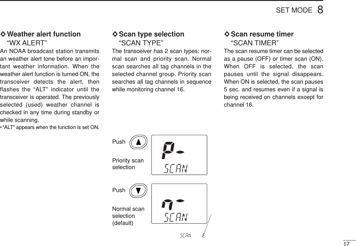
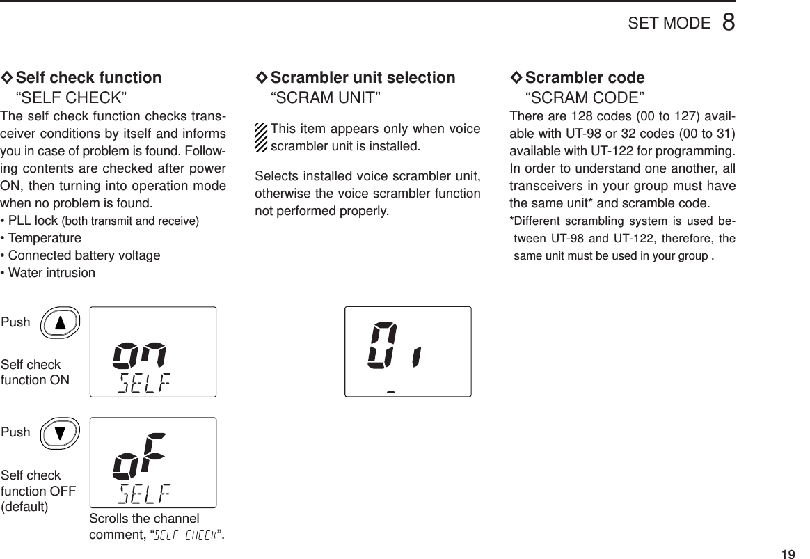
![SET mode is used to change the condi-tions of 10 transceiver functions: beeptone function, weather alert function,scan type (normal/priority), scan resumetimer, auto scan function, auto watch,automatic backlighting, power saverfunction, self check function, voicescrambler type and scrambling code.When no optional voice scrambler unitis installed, voice scrambler type andscrambling code setting are not qTurn power OFF.wWhile pushing [MONI], turn powerON and continue pushing [MONI]until emits beep.•After beep emission, release [MONI].• Set mode item at comment indicator andcondition at channel number readout aredisplayed.rPush [MONI] to select the desireditem, if necessary.tPush [Y]/[Z] to select the desiredcondition of the item.yTo exit SET mode, push [16].• Turning power OFF, then ON again alsoexits SET mode.■SET mode items×Beep tone “BEEP”You can select silent operation by turn-ing beep tones OFF or you can haveconfirmation beeps sound at the pushof a switch by turning beep tones ON.The beep tone volume is linked with[VOL].8SET MODE16Automatic backlightingWeather alertPower saveScan resumetimerScan typeBeep toneScramblerunit selectionScramblingcodeSelf check functionAuto scanPush• SET mode constructionPushBeep ON(default)Beep OFFPush■SET mode programming](https://usermanual.wiki/ICOM-orporated/IC-M1V.Manual/User-Guide-71868-Page-20.png)
![188SET MODE×Auto scan function“AUTO SCAN”While in standby, this function automat-ically starts the desired scan (normal orpriority scan) 30 sec. after operation. •“SCAN” appears when the function isturned ON.The transceiver has a power savefunction but the power save functiondoes not function when the autoscan function is in use.×Automatic backlighting“BACKLIGHT”This function is convenient for nighttimeoperation. The automatic backlightingturns the backlighting ON when pushingany key except for [PTT].•The backlighting automatically turns OFF5 sec. after operation.•Push [MONI] to turn the backlighting ONwithout changing the operating condition.• The backlighting ON when entering SETmode, regardless of this setting.×Power save function“POWER SAVE”The power saver function reduces cur-rent drain by deactivating the receivercircuit for present intervals.The power save function does notfunction when the auto scan functionis in use.PushPower save ON (default)Power saveOFFPushScrolls the channel comment, “ ”.PushAutomaricbacklighting ON (default)Automaricbacklighting OFFPushScrolls the channel comment, “ ”.PushAuto scanON Auto scanOFF (default)PushScrolls the channel comment, “ ”.](https://usermanual.wiki/ICOM-orporated/IC-M1V.Manual/User-Guide-71868-Page-22.png)
![2210 SPEAKER-MICROPHONE■Speaker-microphonedescriptionsIMPORTANT: KEEP the [SP MIC] jack cover attached(transceiver) when speaker-microphone is not in use.Water will not coming into the transceiver even the cover isnot attached, however, the terminals (pins) become rustywhen the connector has wet. NEVER immerse the connector in water. If the connector be-comes wet, be sure to dry BEFORE attaching it to the trans-ceiver.■AttachmentInsert the connector of the speaker-microphone into the[SP MIC] connector on the transceiver and rotates (screws)the connector cover as shown in the diagram below. NOTE: The microphone element is located at the top ofthe speaker-microphone. To maximize the readability ofyour transmitted signal (voice), hold the microphone ap-prox. 2.5 cm (1 inch) from your mouth, and speak at a nor-mal voice level.](https://usermanual.wiki/ICOM-orporated/IC-M1V.Manual/User-Guide-71868-Page-26.png)
![11TROUBLESHOOTING23POSSIBLE CAUSE• The battery is exhausted.• Bad connection to the battery pack.• Squelch level is too deep.• [OFF/VOL] level is too low.•Some channels are for low power orreceive only.• The battery is exhausted.•The output power is set to low or extralow.• Lock function is activated.• “TAG” channel is not programmed.• Auto scan function is activated.• Beep tone is turned OFF.• Optional voice scrambler is turned OFF.• Scramble code is not set correctly.PROBLEMNo power comes ON.No sound comes fromthe speakerTransmitting is impossi-ble, or high power can-not be selected.The displayed channelcannot be changed.Scan does not start.Scan starts automati-cally.No beep sounds.Receive signal cannotbe understood.SOLUTION• Recharge the battery pack.• Check the connection to the transceiver.• Set squelch to the threshold point.• Set [OFF/VOL] to a suitable level.• Change channels.• Recharge the battery pack.• Push [H/L] to select high power.•Push [H/L•LOCK] for 2 sec. to cancel thefunction.•Set the desired channels as “TAG” chan-nels.•Cancel the auto scan function in SETmode.• Turn the beep tone ON in SET mode.• Turn the optional voice scrambler ON.• Reset the scramble code.REF.p. 15p. 2p. 6p. 7pgs.5, 7p. 15p. 7p. 6p. 12p. 14p. 13p. 8p. 8](https://usermanual.wiki/ICOM-orporated/IC-M1V.Manual/User-Guide-71868-Page-27.png)