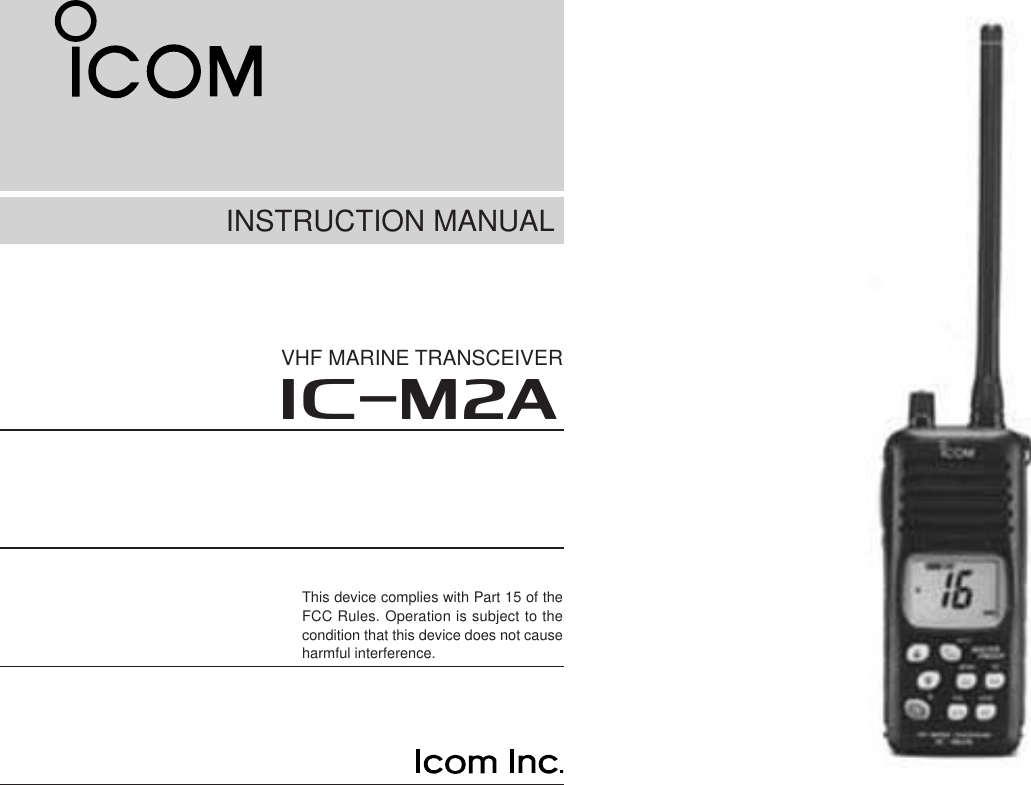
ICOM orporated IC-M2A VHF Marine Transceiver User Manual IC M2A Instruction manual
ICOM Incorporated VHF Marine Transceiver IC M2A Instruction manual
UserManual.wiki
>
ICOM orporated
>
IC M2A User Manual
Instruction Manual
Navigation menu
Upload a User Manual
Namespaces
Wiki Guide
HTML
PDF
Info
Views
User Manual
Discussion / Help
Navigation
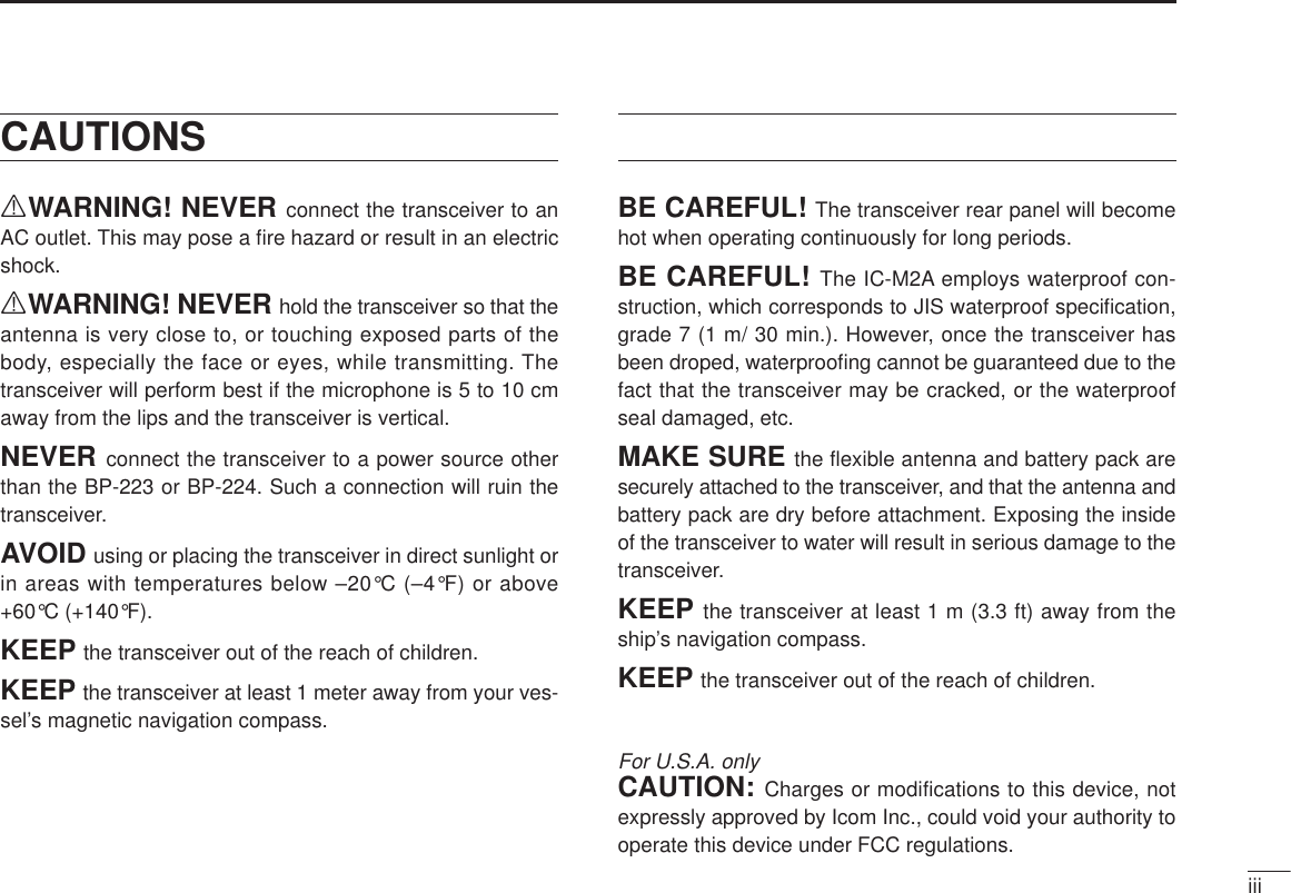
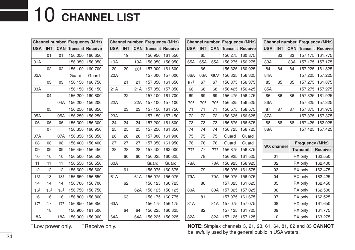
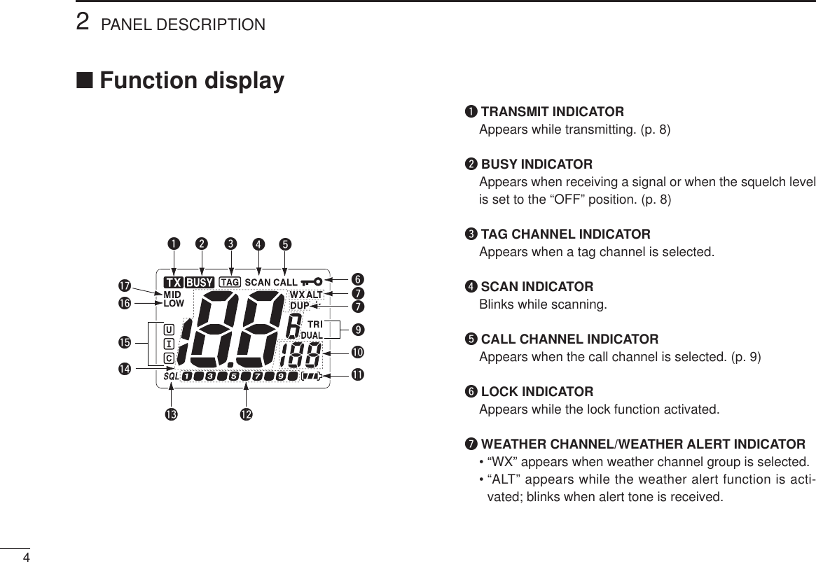
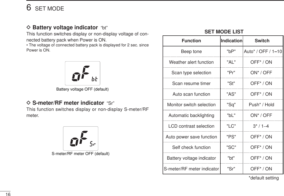
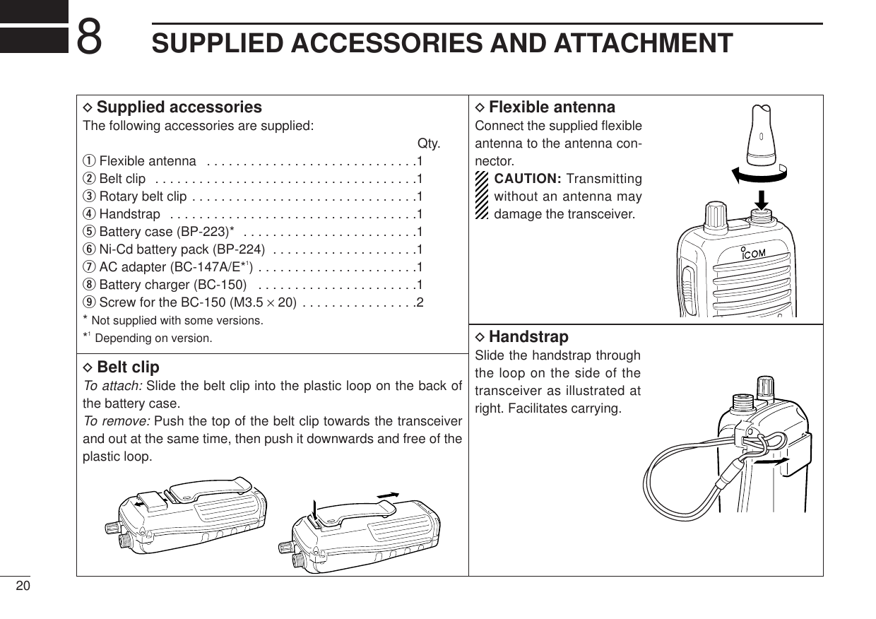
![22PANEL DESCRIPTION■Front panelqCHANNEL/WEATHER CHANNEL SWITCH[CH/WX•U/I/C]• Selects and toggles the regular channelsand weather channel when pushed momen-tarily.• Selects one of 3 regular channels in se-quence when pushed for 1 sec.- International, U.S.A. and Canadian channelsare available.wCHANNEL UP/DOWN SWITCHES [ ]/[ ]• Select an operating channel in the selectedchannel group.• Selects the set mode condition of the item.eCHANNEL 16 SWITCH [16 • 9]• Selects channel 16 when pushed.• Selects the call channel when pushed for 1sec.• Enters call channel write mode when thecall channel is selected and this switch ispushed for 3 sec.rSCAN/TAG SWITCH [SCAN • TAG]• Starts and stops normal or priority scanwhen tag channels are programmed.• Sets and clears the displayed channel as atag (scanned) channel when pushed for 1sec.• While pushing this switch, turn the powerON to clears all tag channels in the selectedregular channel group.tTRANSMIT POWER/LOCK SWITCH[H/L • LOCK]• Toggles high and low power when pushed.• Toggles the lock function ON/OFF whenpushed for 1 sec.yDUALWATCH / TRI-WATCH SWITCH[DW•TRI]• Starts dualwatch when pushed momentarily.• Starts tri-watch when pushed for 1 sec.• Stops dualwatch/tri-watch when either is ac-tivated.uSQUELCH SWITCH [SQL]• Push this switch, then set the squelch levelwith the UP/DOWN [ ]/[ ] switches. (p. 6)wqertyu](https://usermanual.wiki/ICOM-orporated/IC-M2A/User-Guide-178909-Page-8.png)
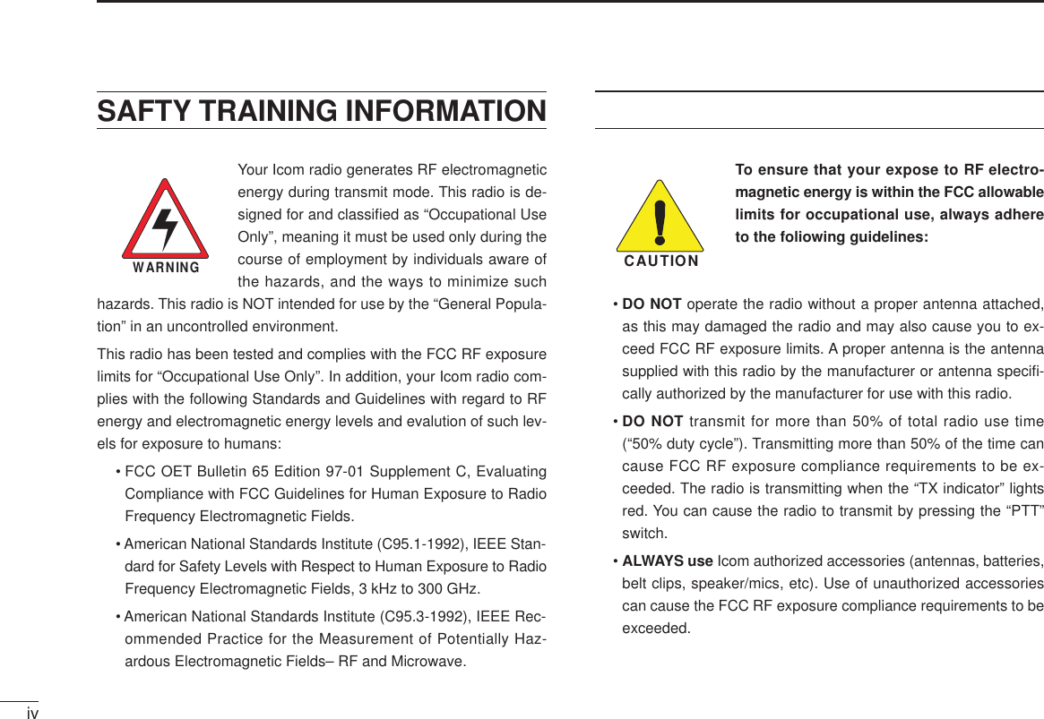
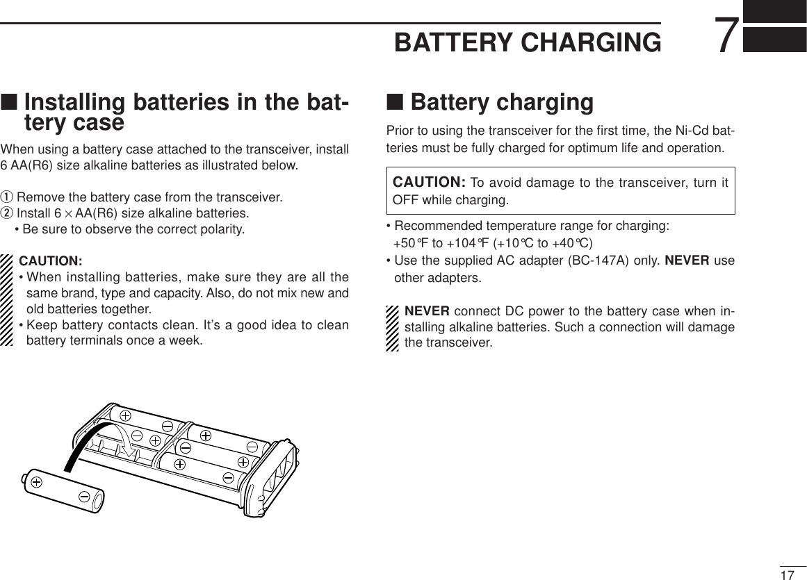
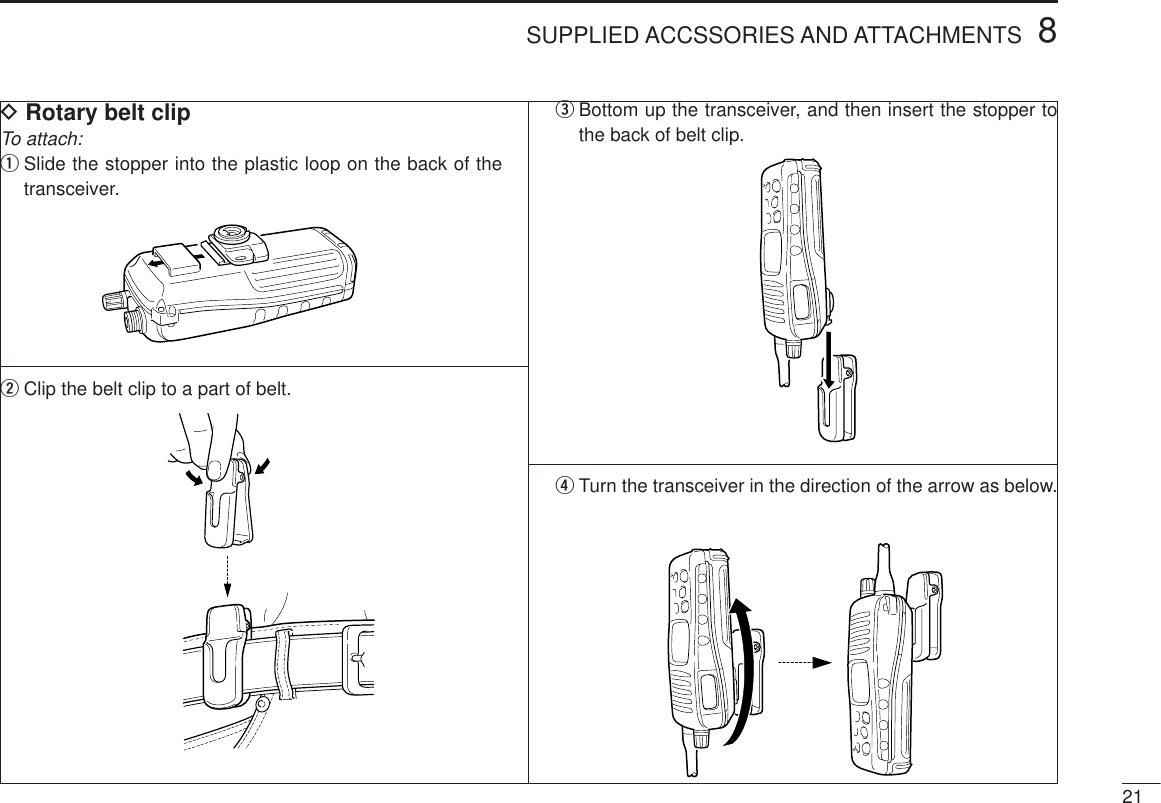
![32PANEL DESCRIPTION■Top and side panelsqANTENNA CONNEC-TORConnects the supplied an-tenna.wVOLUME CONTROL[OFF/VOL]Turns power ON and ad-justs the audio level.ePTT SWITCH [PTT]Push and hold to transmit;release to receive.qweïBATTERY CASE RELEASE BUTTONTo remove the battery case:Turn the screw counterclockwise, then pull the battery packin the direction of the arrow as shown below.To attach the battery case:Insert the battery case in the IC-M2A completely, then turnthe screw clockwise.](https://usermanual.wiki/ICOM-orporated/IC-M2A/User-Guide-178909-Page-9.png)
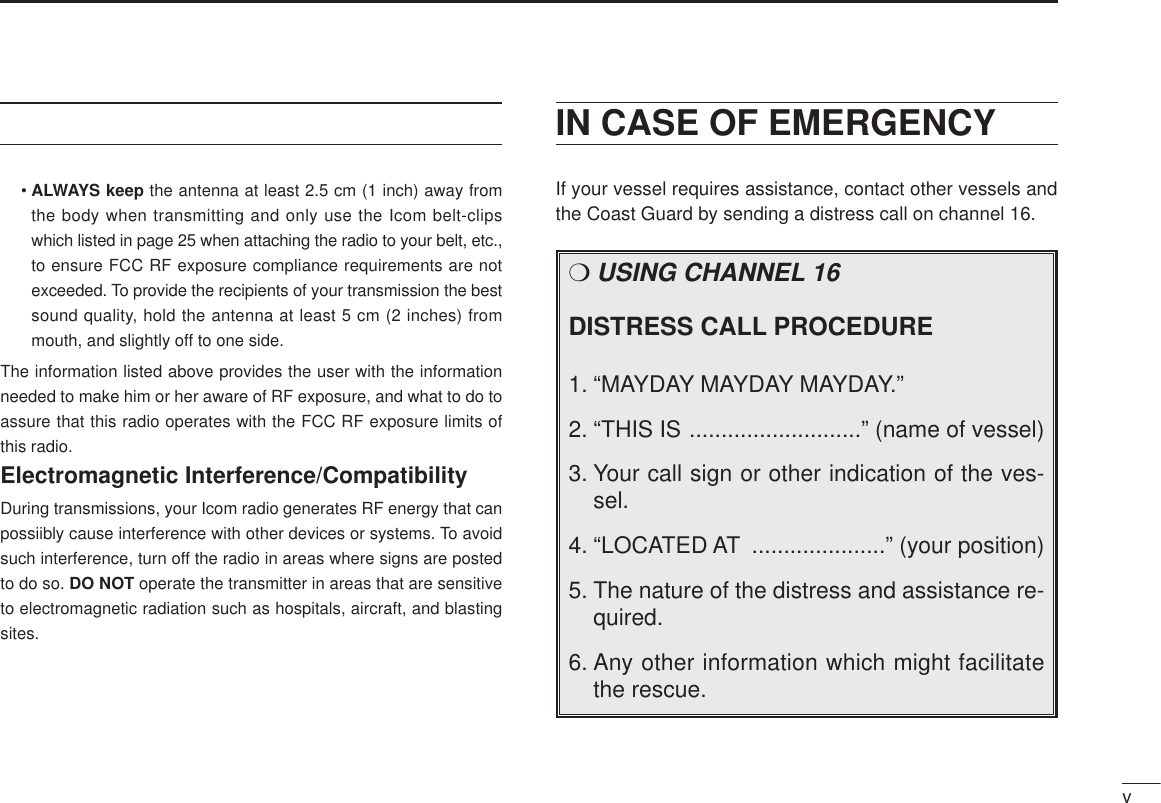
![63BASIC OPERATION■Channel selectionDChannel 16Channel 16 is the distress channel. It is used for establishinginitial contact with another station and for emergencycommunications. Channel 16 is monitored duringdualwatch/tri-watch. While standing by you are required tomonitor channel 16.DChannel (Call channel)Channel 9 is the leisure-use call channel. Each regularchannel group has a separate call channel. The call channelis monitored during tri-watch. The call channels can beprogrammed (p. 9) and are used to store your most often-used channels in each channel group for quick recall.• Push [16 • 9] for 1 sec. to selectthe call channel for the selectedchannel group.- “CALL” and call channel numberappear.- Each channel group can have itsown call channel after changing acall channel.16 9PushDU.S.A., Canadian and international channelsThere are 61 U.S.A., 57 Canadian and 57 international chan-nels. These channel groups may be specified for the operat-ing area.qPush [CH/WX] to select a regular channel.- If a weather channel appears, push [CH/WX] again.wPush [ ]/[ ] switches to select a channel.- “DUP” appears for duplex channels.eTo change the channel group, push [CH/WX • U/I/C] for 1sec.- U.S.A., Canadian and international channels can be selected insequence.Push for 1 sec. U.S.A. channelsCanadian channelsInternational channelsCH/WXU/I/CCH/WXU/I/CCH/WXU/I/C](https://usermanual.wiki/ICOM-orporated/IC-M2A/User-Guide-178909-Page-12.png)
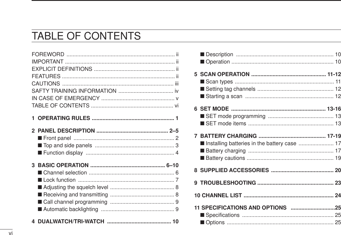
![73BASIC OPERATIONDWeather channelsThere are 10 weather channels. These are used for monitor-ing weather channels from the NOAA (National Oceano-graphic and Atmospheric Administration) broadcasts. The IC-M2A can detect a weather alert tone on a selectedweather channel while scanning. See the “SET mode items”on p. 13.• Push [CH/WX] to select weather channels.■Lock functionThis function electronically locks all keys and switches to pre-vent accidental frequency changes and function access.• Push [H/L • LOCK] for 1 sec. to turn the lock function ON andOFF.- Only [PTT], [H/L] and [SQL] are functional.Appears while thelock function is used.■Adjusting the squelch levelThe IC-M2A has a squelch even though there is no controlknob for it. In order to receive signals properly, as well as forscan to function, the squelch must be adjusted to a suitablelevel.qPush [SQL], then select the squelch level with the [ ]/[ ]keys.- There are 11 squelch levels to choose from: 0 is completelyopen; 10 is the maximum squelch level.- When no key pushes within 5 sec., the display returns to normalindication.wPush [SQL] once more when the desired squelch level isindicated in the function display.- The display returns to normal indication.(Level 10: Max. squelch level)Squelch level indicatorAppears while squelch level adjusting.](https://usermanual.wiki/ICOM-orporated/IC-M2A/User-Guide-178909-Page-13.png)
![8qRotate [OFF/VOL] clockwise to turn power ON.- Use the squelch function to mute any audio noise if necessary.Refer to the previous page for details.wPush* [SQL.MONI] for 1 sec., and rotate volume to setaudio output level.*According to Monitor switch selection in SET mode (p. 14).ePush [ ]/[ ] to select the desired channel.- When receiving a signal, appears and audio is emittedfrom the speaker.- Further adjustment of [OFF/VOL] may be necessary at thispoint.rPush [H/L] to select the output power if necessary.- “LOW” appears when low power is selected.- Choose low power to conserve battery power, choose highpower for longer distance communications.- Some channels are for low power only.tPush and hold [PTT] to transmit, then speak into themicrophone.-appears.(Appears the S/RF meter while S/RF meter is ON.)- Channel 70 cannot be used for transmission (for GMDSS use).yRelease [PTT] to receive.TXBUSY■Receiving and transmittingCAUTION: Transmitting without an antenna maydamage the transceiver.IMPORTANT: To maximize the readability of your trans-mitted signal, pause a few sec. after pushing [PTT], holdthe microphone 5 to 10 cm (2 to 4 inches) from yourmouth and speak at a normal voice level.NOTE: The transceiver has power save function to con-serve the battery power and cannot be turned OFF. Thepower save function activates automatically when no sig-nal is received for 5 sec.w Set volumee˚ Set channel r˚ Set output powert Push to transmity Release to receiveq Power ONw Set volume3BASIC OPERATION](https://usermanual.wiki/ICOM-orporated/IC-M2A/User-Guide-178909-Page-14.png)
![93BASIC OPERATION■Call channel programmingThe call channel switch is used to select channel 9 by default,however, you can program your most often-used channels ineach channel group for quick recall.qPush [CH/WX • U/I/C] for 1 sec.several times to select the de-sired channel group (USA, INT,CAN) to be programmed.wPush [16 • 9] for 1 sec. to selectthe call channel of the selectedchannel group.- “CALL” and call channel numberappear.ePush [16 • 9] again for 3 sec.(until long beep changes to 2short beeps) to enter call chan-nel programming condition.- Call channel number and channelgroup to be programmed flash.rPush [ ]/[ ] to select the de-sired channel.tPush [16 • 9] to program the dis-played channel as the call chan-nel.- The call channel number and chan-nel group stop flashing.■Automatic backlightingThis function is convenient for nighttime operation. The auto-matic backlighting can be activated in SET mode. (p. 15)• Push any key except for [PTT] to turn the backlighting ON.- The backlighting is automatically turned OFF after 5 sec. of in-activity.](https://usermanual.wiki/ICOM-orporated/IC-M2A/User-Guide-178909-Page-15.png)
![104DUALWATCH/TRI-WATCH■DescriptionDualwatch monitors channel 16 while you are receiving an-other channel; tri-watch monitors channel 16 and the callchannel while receiving another channel.DUALWATCH/TRIWATCH SIMULATION• If a signal is received on channel 16, dualwatch/tri-watch pauseson channel 16 until the signal disappears.• If a signal is received on the call channel during tri-watch, tri-watch becomes dualwatch until the signal disappears.• To transmit on the selected channel during dualwatch/tri-watch,push and hold [PTT].Call channelDualwatch Tri-watch■OperationqSelect the desired operating channel.wPush [DW • TRI] momentarily to start dualwatch; push [DW•TRI] for 1 sec. to start tri-watch.- “DUAL” flashes during dualwatch; “TRI” flashes during tri-watch.- Beep tones sound when a signal is received on channel 16.- Tri-watch becomes dualwatch when receiving a signal on the callchannel.eTo cancel dualwatch/tri-watch, push [DW • TRI] again.[Example]: Operating tri-watch on INT channel 07.Tri-watch starts.Push for 1 sec.Signal is received on call channel.Signal received on channel 16 takes priority.Tri-watch resumes after the signal disappears.DWTRI](https://usermanual.wiki/ICOM-orporated/IC-M2A/User-Guide-178909-Page-16.png)
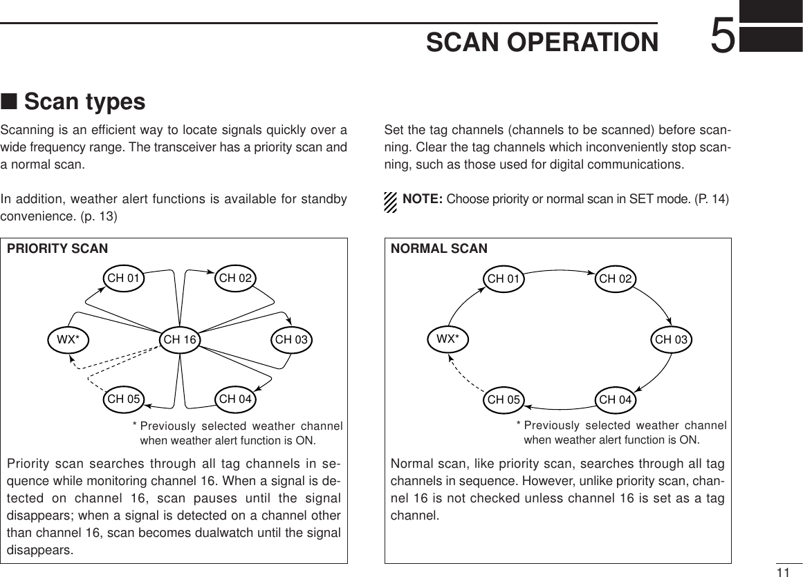
![125SCAN OPERATION■Setting tag channelsFor more efficient scanning, add desired channels as tagchannels or clear tag channels for unwanted channels. Chan-nels set as non-tag channels will be skipped during scanning.Tag channels can be assigned to each channel group (USA,CAN, INT) independently.qSelect the desired channel group (USA, CAN, INT) bypushing [CH/WX • U/I/C] for 1 sec., if desired.wSelect the desired channel to set as a tag channel.ePush [SCAN • TAG] for 1 sec. to set the displayed channelas a tag channel.- appears in the function display.rTo cancel the tag channel setting, push [SCAN • TAG] for 1sec.- disappears.• Clearing all tag channels in the selected channel groupWhile pushing [SCAN • TAG], turn the power ON to clear alltag channels in the channel group.TAGTAG■Starting a scanSet scan type, weather alert function and scan resume timerin advance using SET mode. (pgs. 13, 14)qSelect the desired channel group (USA, CAN, INT) bypushing [CH/WX • U/I/C] for 1 sec., if desired.- When the weather alert function is in use, select the desiredweather channel with [CH/WX] and the channel selector.wPush [SCAN • TAG] to start priority or normal scan.- “SCAN” appears and flashes in the function display.- “16” appears during priority scan.- When a signal is detected, scan pauses until the signal disap-pears or resumes after pausing 5 sec. according to SET modesetting. (Channel 16 is still monitored during priority scan.)- Push [ ]/[ ] to check tag channels, to change the scanningdirection or resume the scan manually.eTo stop the scan, push [SCAN • TAG].- “SCAN” disappears.- Pushing [PTT], [16 • 9], [CH/WX] or [DW • TRI] also stops thescan.Scan starts. Scan pauses when receiving a signal and audio is emitted.Push Push to stop the scan.SCANTAGSCANTAG[Example]: Starting a normal scan.](https://usermanual.wiki/ICOM-orporated/IC-M2A/User-Guide-178909-Page-18.png)
![136SET MODEWeather alert function OFF (default)■SET mode programmingSET mode is used to change the conditions of 6 transceiverfunctions: the beep tone function, the automatic backlighting,weather alert function, normal/priority scan, scan resumetimer and power save function.qTurn power OFF.wWhile pushing [SQL], turn power ON and continue push-ing [SQL] until “bP” appears.eRelease [SQL].rPush [SQL] to select the desired item, if necessary.tPush [ ]/[ ] to select the desired condition of the item.yTo exit SET mode, turn the power OFF, then ON again, orpush [16•9].WeatheralertS/RFmeterScan resumetimerAutoscanAutomaticbacklighting MonitorswitchLCDcontrastSelfcheckBatteryvoltageAutopower saveScantypeBeep tonePush SQLMONI■SET mode itemsDBeep tone “bP”You can select silent operation by turning beep tones OFF oryou can have confirmation beeps sound at the push of aswitch by turning beep tones ON. The beep tone volume islinked with [OFF/VOL].DWeather alert function “AL”NOAA broadcast stations transmit weather alert tones beforeimportant weather announcements. When the weather alertfunction is turned ON, the transceiver detects the alert, thenflashes the “ALT” indicator until the transceiver is operated.The previously selected (used) weather channel is checkedperiodically during standby or while scanning.• “ALT” appears when the function is set ON.Beep tone AUTO (default)](https://usermanual.wiki/ICOM-orporated/IC-M2A/User-Guide-178909-Page-19.png)
![146SET MODEDScan type selection “Pr”The transceiver has 2 scan types: normal scan and priorityscan. Normal scan searches all tag channels in the selectedchannel group. Priority scan searches all tag channels in se-quence while monitoring channel 16.DScan resume timer “St”The scan resume timer can be selected as a pause (OFF) ortimer scan (ON). When OFF is selected, the scan pausesuntil a received signal disappears. When ON is selected, thescan pauses for 5 sec. after receiving a signal and then re-sumes even if the signal is still being received.DAuto scan function “AS”While in standby, this function automatically starts the desiredscan (normal or priority scan) 30 sec. after operation.• The comment indicator indicates “SCAN” while scanning.DMonitor switch selection “Sq”The monitor switch can be set as a ‘sticky’ switch. When setto the sticky condition, each push of [SQL] toggles the moni-tor function ON and OFF.• PUSH (Pu): Set the monitor switch to normal (default).• HOLD (Ho): Set the monitor switch to sticky switch.Normal scan (default) Priority scanAuto scan OFF (default)Monitor switch PUSH (default)Scan timer OFF (default)](https://usermanual.wiki/ICOM-orporated/IC-M2A/User-Guide-178909-Page-20.png)
![156SET MODEDAutomatic backlighting “bL”This function is convenient for nighttime operation. THe au-tomatic backlighting turns the backlighting ON when pushingany key except fpr [PTT].• The backlighting is automatically turned OFF after 5 sec. of inactiv-ity.DLCD contrast selection “LC”The contrast of the LCD can be adjusted from 4 levels.• 1 (low contrast) – 4 (high contrast); 3 (default)DAuto power save function “PS”The power save function reduces current drain by deactivat-ing the receiver circuit for preset intervals.DSelf check function “SC”The self check function checks transceiver conditions by it-self, and informs you in case a problem is found. The follow-ing items are checked after the power is turned ON, then,switches to operation mode.• PLL lock (both transmit and receive)• Temperature• Connected battery voltage• Water intrusionAutomatic backlighting ON (default)LCD constrastAuto power save ON (default)Self check OFF (default)](https://usermanual.wiki/ICOM-orporated/IC-M2A/User-Guide-178909-Page-21.png)
![239TROUBLESHOOTINGPROBLEM POSSIBLE CAUSE SOLUTION REF.No sound comes fromthe speaker.• Squelch level is too deep.• Volume level is too low.• Speaker has been exposed to water.p. 7p. 8—• Set squelch to the threshold point.• Set [OFF/VOL] to a suitable level.• Drain water from the speaker.No power comes ON. • The battery is exhausted.• Bad connection to the battery pack.p. 18p. 3• Recharge the battery pack.• Check the conection to the transceiver.Transmitting is impos-sible, or high powercan not be selected.• Some channels are for low power or re-ceive only.• The battery is exhausted.• The output power is set to low.pgs.2,4p. 18p. 2• Change channels.• Recharge the battery pack.• Push [H/L] to select high power.The display channelcannot be changed.• Lock function is activated. • Push [H/L • LOCK] for 1 sec. to cancel thefunction.p. 2Scan does not start. • “TAG” channels are not programmed. • Set the desired channels as “TAG” chan-nels.p. 12No beeps sound. • Beep tones are turned OFF. • Turn the beep tones ON in SET mode. p. 13](https://usermanual.wiki/ICOM-orporated/IC-M2A/User-Guide-178909-Page-29.png)