ICOM orporated IC-M45A VHF-FM Marine Transceiver User Manual IC M45A Manual
ICOM Incorporated VHF-FM Marine Transceiver IC M45A Manual
UserManual.wiki
>
ICOM orporated
>
IC M45A User Manual
Manual
Navigation menu
Upload a User Manual
Namespaces
Wiki Guide
HTML
PDF
Info
Views
User Manual
Discussion / Help
Navigation
![22PANEL DESCRIPTION■Front panelqCHANNEL UP/DOWN SWITCHES [YUP]/[ZDN]Push to select an operating channel. (p. 6)• Push and hold to ‘speed’ scroll up or down through the availablechannels.wSCAN SWITCH [SCAN • TAG]➥Push to start/stop scanning. (p. 9)• Scan type can be selected in SET mode. (p. 12)➥Push for 1 sec. to toggle the tag setting for the displayedchannel. (p. 9)eHIGH/LOW POWER SWITCH [H/L • DIM]➥Toggles between high and low output powers. (p. 8)➥While pushing, push the [UP]/[DN] switches to adjust thedisplay backlighting. (p. 10)➥While pushing, push [SCAN] for 3 sec. to clear all tagchannels. (p. 9)rCHANNEL SWITCH [CH/WX • DUAL]➥Push to toggle between regular channel mode andweather channel mode. (p. 6)• While in regular channel mode, push [H/L] + [CH/WX] tochange channel groups.VHF MARINE iM45PWRSQUELCHOFFDCH WX9UALUDIMTAGHUDNPSCANLICVOL16qwe rty uIC-M45A Manual 99.3.29 2:45 PM Page 2](https://usermanual.wiki/ICOM-orporated/IC-M45A/User-Guide-38942-Page-6.png)
![32PANEL DESCRIPTION■MicrophoneqCHANNEL UP/DOWN SWITCHES [Y]/[Z]Select an operating channel in the selected channel group.• These switches can be used instead of the transceiver’s[UP]/[DN] switches.wHIGH/LOW POWER SWITCH [HI/LO]The same function as the transceiver’s [H/L] switch—tog-gles between high and low output powers.• Pushing this key at power ON turns the microphone keysON/OFF.HI/LO➊➋➥Push for 1 sec. to start/stop dual (tri) watch. (p. 7)• Use SET mode to select dual or tri-watch in advance. (p. 12)tCHANNEL 16 SWITCH [16 • 9]➥Push to select channel 16. (p. 5)➥Push for 1 sec. to select the call channel (channel 9 bydefault). (p. 5)• Each group can have it’s own call channel pro-grammed.➥Push for 3 sec. (when a call channel is selected) to entercall channel write mode. (p. 10)• Channel indication flashes.ySQUELCH CONTROL [SQUELCH]Rotate clockwise to eliminate audio noise. (p. 7)uPOWER/VOLUME CONTROL [PWR/VOL]Turns power ON and OFF and adjusts the audio outputlevel.IC-M45A Manual 99.3.29 2:45 PM Page 3](https://usermanual.wiki/ICOM-orporated/IC-M45A/User-Guide-38942-Page-7.png)
![42PANEL DESCRIPTION■Function displayqTRANSMIT INDICATORAppears while transmitting. (p. 8)wBUSY INDICATORAppears when receiving a signal or when [SQUELCH] isrotated too far clockwise. (p. 7)eCHANNEL INDICATORShows the operating channel (pgs. 5, 6)rTAG CHANNEL INDICATORAppears when the selected channel is set as a tag chan-nel. (p. 9)tDUALWATCH INDICATORAppears and flashes during dualwatch operation. (p. 7)yTRI-WATCH INDICATORAppears and flashes during tri-watch operation. (p. 7)uSCAN INDICATORAppears and flashes during scan operation. (p. 9)iDUPLEX INDICATORAppears when the selected channel is a duplex channel.(p. 6)oCALL CHANNEL INDICATORAppears when the call channel is selected. (p. 5)!0 MODE INDICATORS (p. 5, 6)➥“USA” shows that USA channels are selected.➥“CAN” shows that Canadian channels are selected.➥“INT” shows that international channels are selected.➥“WX” shows that weather channels are selected.!1 LOW POWER INDICATORShows that low output power is selected. (p. 8)LOW CALLCANUSAINTWXTXTAGDUALSCANDUPTRIBUSYwq ertyuio!1!0IC-M45A Manual 99.3.29 2:45 PM Page 4](https://usermanual.wiki/ICOM-orporated/IC-M45A/User-Guide-38942-Page-8.png)
![53BASIC OPERATION■Power ON➀Rotate [PWR/VOL] clockwise to turn power ON.➁Operate the transceiver as indicated in the following sec-tions.DLow voltage indicatorWhen “b” appears and flashes asshown at right, there is a DC powersource problem. In this case, checkyour vessel’s battery and DC powercable.LOW CALLCANUSAUSAINTALTWXTXTAGDUALSCANDUPTRIBUSY All display indicationsappear briefly.Channel 16 is automaticallyselected.■Channel selectionDChannel 16Channel 16 is the distress channel. It is used for establishinginitial contact with another station and for emergency com-munications. Channel 16 is monitored during dual/tri-watch.While standing by you are required to monitor channel 16.DCall channelThe call channel is used to store your most often-used chan-nel for quick recall. In addition, the call channel is monitoredduring tri-watch. The default setting for the call channel ischannel 9 which is for leisure boat use. A separate call chan-nel can be set for each channel group (USA, CAN and INT).USAUSAUSAPushor hang the microphoneon the microphone hanger.16Pushfor 1 sec. “CALL” indicates that thecall channel is selected.169CALLUSAIC-M45A Manual 99.3.29 2:45 PM Page 5](https://usermanual.wiki/ICOM-orporated/IC-M45A/User-Guide-38942-Page-9.png)
![63BASIC OPERATIONDUSA, Canadian and international channelsThere are 61 USA, 57 Canadian and 57 international chan-nels. These channel groups may be specified for the operat-ing area.➀Push [CH/WX] to select a regular channel.• If regular channels (USA, CAN or INT) are already selected, thisstep is not necessary.➁Push [UP]/[DN] to select a channel.• “DUP” appears for duplex channels.➂To change the channel group, push [CH/WX] + [H/L] simul-taneously.• USA, Canadian and international channels can be selected in se-quence.USAINTDUPCANTAGU.S.A. channelsPush simultaneouslyInternational channels Canadian channelsCH WXUHLICDWeather channelsThere are 10 weather channels. These are used for monitor-ing NOAA (National Oceanographic and Atmospheric Admin-istration) weather broadcasts.✔CONVENIENTWeather alert function:NOAA broadcast stations transmit aweather alert tone before important weather announcements.When the weather alert function is turned ON, the “ALT” indi-cator flashes until a switch is pushed. This function is acti-vated when a weather channel is selected or during any scan.See “SET mode items” on p. 12.PushWXCH WXIC-M45A Manual 99.3.29 2:45 PM Page 6](https://usermanual.wiki/ICOM-orporated/IC-M45A/User-Guide-38942-Page-10.png)
![73BASIC OPERATION■Receiving➀Rotate [PWR/VOL] to turn power ON.➁Rotate [SQUELCH] fully counterclockwise.➂Adjust [PWR/VOL] to a suitable listening level.➃Rotate [SQUELCH] clockwise until the audio noise disap-pears.➄Select a channel. See pgs. 5–6 for details.• When a signal is received:➧The squelch opens.➧Audio is emitted from the speaker.➧“BUSY” appears in the function display.➅When an interrupting signal is received, rotate [SQUELCH]deeply clockwise.DDual/tri-watch functionsThese functions allow you to conveniently check the distresschannel (ch 16) or, both the distress and leisure call channel(ch 9; programmable) while receiving another channel. Whenreceiving a signal on one of these channels, the transceiverstops on the channel until the signal disappears.Depending on your preference, select dual watch or tri-watchin advance in SET mode (p. 12). Dual watch is the default set-ting.When dual watch is selected in SET mode:➥Push [CH/WX • DUAL] for 1 sec. to start dual watch.When tri-watch is selected in SET mode:➥Push [CH/WX • DUAL] for 1 sec. to start tri-watch.➥Push any switch to cancel dual/tri-watch and return to nor-mal operation.USADUALUSADUALBUSYChecking channel 16 every 2 sec. When receiving a signal on channel 16. Channel 16 is monitored until the signal disappears.USATRICALLUSATRIBUSYUSATRIBUSYChecking channel 16 and the call channel every 2 sec.When receiving a signal on channel 16, channel 16 has priority.When receiving a signal on the call channel, the call channel is monitored while checking ch 16 in 2 sec. intervals.IC-M45A Manual 99.3.29 2:45 PM Page 7](https://usermanual.wiki/ICOM-orporated/IC-M45A/User-Guide-38942-Page-11.png)
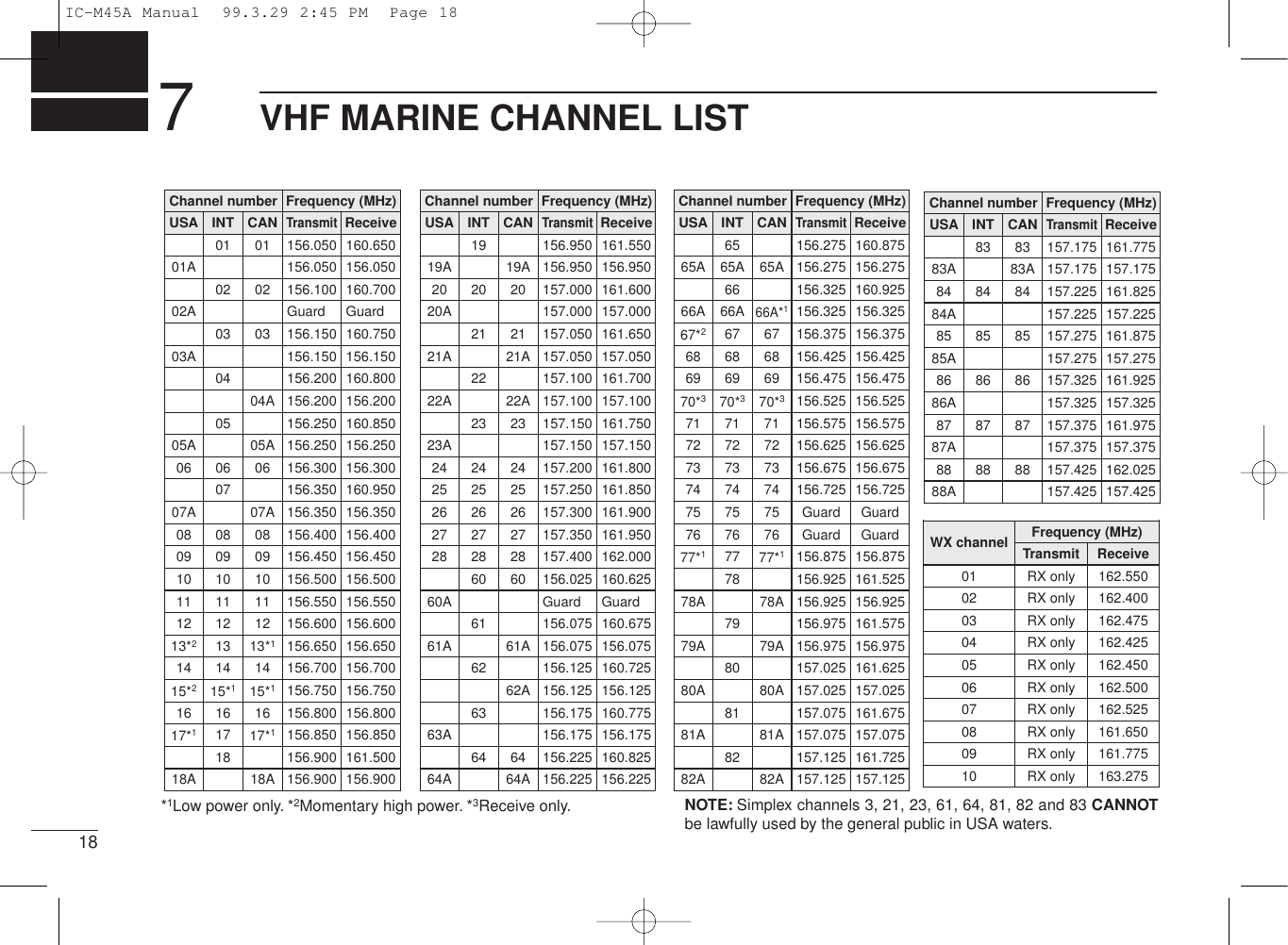
![83BASIC OPERATION■TransmittingBefore transmitting, read the call procedures at right.➀Select an operating channel. See pgs. 5–6 for details.➁Push [H/L] to select a transmit output power.• “LOW” appears when low output power is selected.• High power cannot be selected on some channels. Refer to thechannel list on p. 18.➂Push and hold the [PTT] switch to transmit.•“$” appears.➃Speak into the microphone at your normal voice level.• Do not hold the microphone too closely to your mouth or speak toloudly. This may distort the signal.➄Release the [PTT] switch to receive.vIMPORTANT: In order to maximize the readability ofyour transmitted signal, pause for a moment after push-ing [PTT], hold the microphone 15–20 cm from yourmouth, then speak into the microphone at an even, nor-mal voice level.MOMENTARY HIGH POWEROn USA channels 13, 15 and 67, transmission using highpower is momentarily possible. To use high power, pushand hold [H/L] while transmitting.TIME-OUT TIMER (USA version only)The transceiver has a time-out timer function to preventcontinuous, long transmissions. Transmit is automaticallyinhibited after 5 min. of continuous transmission.CALL PROCEDURESYou must identify yourself when you transmit and you mustrespect time limits.1) Give your call sign each time you call another vessel or acoast station. If you have no call sign, identify the stationby giving the vessel name and the name of the license.2) Give your call sign at the end of each transmission thatlasts more than 3 minutes.3) You must pause and give your call sign at least onceevery 15 minutes during long ship-to-shore calls.4) Keep your calls short (less than 3 minutes). Wait 2 min-utes before repeating a call.5) Unnecessary transmissions are not allowed.IC-M45A Manual 99.3.29 2:45 PM Page 8](https://usermanual.wiki/ICOM-orporated/IC-M45A/User-Guide-38942-Page-12.png)
![93BASIC OPERATION■Scan functionThe transceiver has a high speed scan function for standingby on utility signals. The scan speed is 8 channel/sec. (exceptwhen the weather alert function is in use).Two scan types are available:normal scan (scans all tagchannels in sequence) and priority scan (checks channel 16while scanning). These scans can be selected in SET mode(p. 12).DSetting tag channelsYou can specify channels as tag channels for efficient scan-ning. Tag channels can be set for each channel group (USA,CAN, INT) independently.➥Select the desired channel, then push [SCAN • TAG] for 1sec. to toggle the tag setting.✔Clearing all tag channelsWhile pushing [H/L], push [SCAN • TAG] for 3 sec. until thelong beep becomes 2 short beeps.• All tag channels in the selected channel group are released.USATAGAppears when the channel isspecified as a tag channel.DScan operation➀Select the desired channel group (USA, CAN, INT or WX)channels with [CH/WX] + [H/L] (or [CH/WX] only forweather channels).• When the weather alert function is in use, select the desired WXchannel in the display, then perform the above step.➁Push [SCAN] to start scanning.• “SCAN” appears and flashes in the function display.• “16” appears during priority scan.➂To stop the scan, push [SCAN] again.• “SCAN” disappears.✔Scan resume timerWhen a signal is detected, scan pauses until the signal dis-appears or resumes after pausing 5 sec., according to theSET mode setting. (p. 12)✔Confirming tag channelsWhile operating scan, push [UP] or [DN].• Only tag channels are selected.• Stop pushing [UP] or [DN] to resume scan.✔Weather alert functionWhen this function is turned ON (p. 12), the selected weatherchannel is checked during scan. Refer to p. 6 for a descrip-tion of weather alert.IC-M45A Manual 99.3.29 2:45 PM Page 9](https://usermanual.wiki/ICOM-orporated/IC-M45A/User-Guide-38942-Page-13.png)
![103BASIC OPERATION■Call channel programmingPushing [16 • 9] for 1 sec. selects the call channel, channel 9by default, however you can program your most often-usedchannels in each channel group for quick recall.➀Push [CH/WX] + [H/L] one ormore times to select the de-sired channel group (USA,CAN, INT) to be programmed.➁Push [16 • 9] for 1 sec. to se-lect the call channel of the se-lected group.• “CALL” and the call channelnumber appear.➂Push [16 • 9] for 3 sec. to entercall channel write mode.• Call channel and channel groupto be programmed flash.➃Push [UP] or [DN] to selectthe desired channel.USACALLUSATAGCALLUSACALLUSA➄Push any switch to automati-cally program the selectedchannel.• The transceiver returns to normal operation.■Display backlightingThe function display and switches can be backlit for better vis-ibility under low light conditions.While pushing [H/L • DIM], push [UP] or [DN] to adjust thebacklighting.• Backlighting can be set to 1 of 4 intensities or turned OFF.CALLUSAIC-M45A Manual 99.3.29 2:45 PM Page 10](https://usermanual.wiki/ICOM-orporated/IC-M45A/User-Guide-38942-Page-14.png)
![114SET MODE■Entering SET modeSET mode is used to customize operation of the transceiverto suit your operating needs.DTo enter SET mode:➀While pushing [16], turn power ON.• Keep pushing [16] until the initial SET mode display appears.• SET mode is selected.➁To exit SET mode, turn power OFF then ON again.DTo select an item:There are 5 items in SET mode that may be adjusted to suityour operating needs.➀Select SET mode as above.➁Push [16] to select an item; then push [UP]/[DN] to set thecondition for the item.■SET mode itemsBeep tones (p. 12)Normal/priorityscan (p. 12)*1*2Weather alert (p. 12)Scan timer (p. 12)Dual/tri-watch (p. 12)Select aSET modeitem*2Select aSET modecondition*116UDNP*1*2*1*2*1*1*2*1*2*1*2*1*2*1*1*1*2SET mode items above are shown at theirdefault conditions.IC-M45A Manual 99.3.29 2:45 PM Page 11](https://usermanual.wiki/ICOM-orporated/IC-M45A/User-Guide-38942-Page-15.png)
![DSCAN TIMERThis item sets the scan timer ON or OFF.DWEATHER ALERTThis item sets the weather alert function ON or OFF. (p. 6)124SET MODEBeep tones ON (default) Beep tones OFFNormal scan (default) Priority scanWeather alert OFF (default) Weather alert ONScan timer OFF (default) Scan timer ON• Scan pauses on a signal and resumes 5 sec. later. • Scan pauses on a signal until the signal disappears, and resumes 2 sec. after that.Dual watch (default) Tri-watchDBEEP TONESThis item sets the transceiver’s confirmation beep tones(when pushing a switch) ON or OFF.DNORMAL/PRIORITY SCANThis item sets the scan function to normal or priority oper-ation. (See p. 9) DDUAL/TRI-WATCHThis item sets the [CH/WX •DUAL] switch to activate dualwatch or tri-watch. (p. 7)IC-M45A Manual 99.3.29 2:45 PM Page 12](https://usermanual.wiki/ICOM-orporated/IC-M45A/User-Guide-38942-Page-16.png)
![176TROUBLESHOOTINGPROBLEM POSSIBLE CAUSE SOLUTION REF.No power comes on. • Power cord not connected properly.• Blown fuse.• Check the power cord connection.• Check the polarity of the power connection,then, replace the fuse.p. 14p. 13No sound comes from thespeaker.• [SQUELCH] is rotated too far clockwise. • Rotate [SQUELCH] counterclockwise to asuitable position.p. 7Sensitivity is low and onlystrong signals are audible.• [SQUELCH] is rotated too far clockwise.• Antenna feedline or the antenna connectorsolder has poor contact or is short circuited.• Rotate [SQUELCH] counterclockwise to asuitable position.• Check, and if necessary, replace the feedline orsolder the antenna connector again.p. 7p. 14Transmitting is impossible orhigh power cannot beselected.• Transmission is restricted on some channels. • Change channels. p. 18Desired channel cannot beselected.• Different channel group is selected. • Push [CH/WX] + [H/L] to select the appropriatechannel group (U.S.A., INT or CAN).p. 6No display backlighting. • Backlight function is turned OFF. • While pushing [H/L • DIM], push [UP]/[DN] toselect the desired brightness.p. 10Scan does not start. • No “TAG” channels are programmed. • Set channels to be scanned as “TAG” channels. p. 9No beeps sound even when aswitch is pushed.• Beep function is turned OFF. • Set beeps to ON in SET mode. p. 12IC-M45A Manual 99.3.29 2:45 PM Page 17](https://usermanual.wiki/ICOM-orporated/IC-M45A/User-Guide-38942-Page-21.png)