ICOM orporated IC-R2 User Manual US IC R2 IM
ICOM Incorporated US IC R2 IM
UserManual.wiki
>
ICOM orporated
>
IC R2 User Manual
Instruction Manual
Navigation menu
Upload a User Manual
Namespaces
Wiki Guide
HTML
PDF
Info
Views
User Manual
Discussion / Help
Navigation
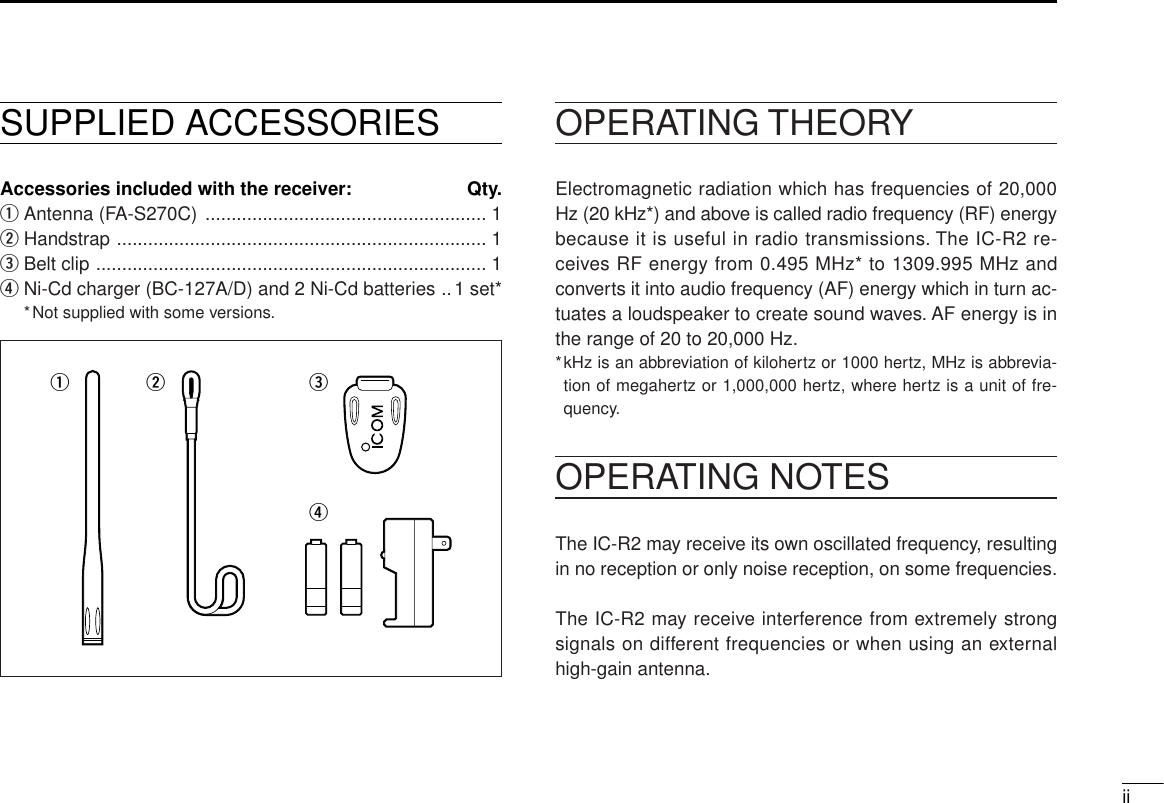
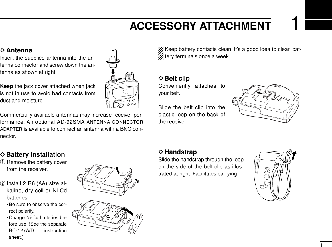
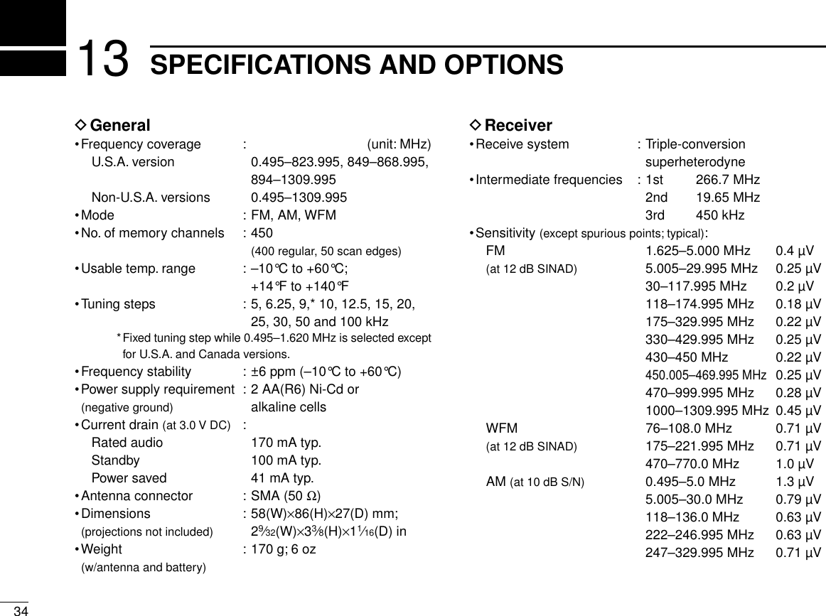
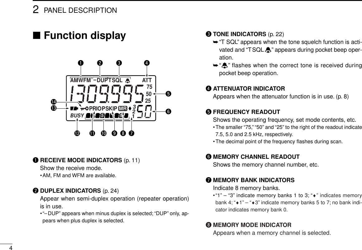
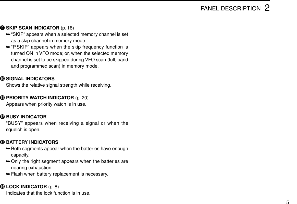
![■Panel descriptionqANTENNA CONNECTOR (p. 1)Connects the supplied antenna.•An optional AD-92SMA is available for connecting an antennawith a BNC connector.wMONITOR SWITCH [SQL] (pgs. 10, 27)➥Push and hold to temporarily open the squelch andmonitor the operating frequency. (default behaviour)➥While pushing, rotate the tuning dial to set the squelchthreshold level.➥Push [FUNC] + [SQL] to toggle the attenuator circuit ONand OFF.eFUNCTION SWITCH [FUNC]While pushing this switch, other switches and tuning dialperform secondary functions.•“Push [FUNC] + a switch” means “while pushing the [FUNC]switch, push the switch.”rBAND SWITCH [BAND]➥Push to select the operating band (VHF, UHF, etc.). (p. 6)•Broadcast band, HF band, 50 MHz band, VHF avionics band,144 MHz band, 300 MHz band, 400 MHz band, 800 MHzband and 1200 MHz band can be selected.•While pushing this switch, rotating [DIAL] also selects the op-erating band.➥Transfers the displayed frequency to the VFO in mem-ory mode. (p. 6)➥Push [FUNC] + [BAND] to enter the scan edge set modein VFO mode. (p. 17)➥Push [FUNC] + [BAND] to enter the bank scan set modein memory mode. (p. 16)22PANEL DESCRIPTIONqwertyuioFunction display(p. 4)SPEAKER!0!1](https://usermanual.wiki/ICOM-orporated/IC-R2/User-Guide-5157-Page-6.png)
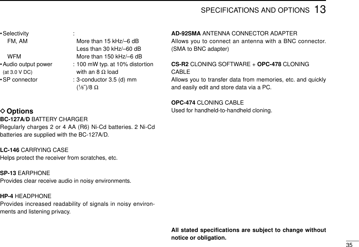
![32PANEL DESCRIPTIONtVOLUME CONTROL SWITCHES [VOLY]/[VOLZ]➥Push to adjust the audio level. (p. 10)➥Push [FUNC] + either switch to start a scan. (p. 16)➥Push [FUNC] + either switch for 2 sec. to start a tonescan. (p. 23)yVFO/MEMORY SWITCH [V/M (MW)]➥Toggles between VFO and memory modes. (p. 6)➥Enters set mode when pushed for 2 sec. (p. 25)➥Push [FUNC] + [(V/M)MW] to enter memory write mode.(p. 12)➥Push [FUNC] + [(V/M)MW] for 1 sec. to write the operat-ing frequency into the selected memory channel in VFOmode. Keep pushing for 2 sec. or more to automaticallyselect the next memory channel, if desired. (p. 12)➥Push [FUNC] + [(V/M)MW] for 1 sec. to write the dis-played frequency into the VFO in memory mode. (p. 13)uPOWER SWITCH [POWER]Push for 2 sec. to toggle the receiver power ON and OFF.iTUNING STEP/MEMORY SKIP SWITCH [TS (SKIP)]➥Enters tuning step set mode. (p. 7)➥Push [FUNC] + [(TS)SKIP] to toggle the frequency skipfunction ON or OFF in VFO mode. (p. 19)➥Push [FUNC] + [(TS)SKIP] for 2 sec. to program the dis-played frequency as a skip frequency during full, bandor programmed scan. (p. 19)➥Push [FUNC] + [(TS)SKIP] to toggle the channel as skip,program skip or non-skip channel in memory mode. (p.18)oMODE/LOCK SWITCH [MODE (LOCK)]➥Selects the receive mode. (p. 11)➥Push [FUNC] + [(MODE)LOCK] to toggle the lock functionON and OFF. (pgs. 8, 28)!0 EXTERNAL SPEAKER JACK [SP]Connects an optional earphone or headphone. The inter-nal speaker will not function when any external equipmentis connected. (See p. 35 for a list of available options.)!1 TUNING DIAL [DIAL]➥Rotate [DIAL] to set operating frequencies, memorychannels, set mode contents, etc. (p. 7)➥While scanning, changes the scanning direction. (p. 16)➥While pushing [SQL], sets the squelch level. (p. 10)➥While pushing [FUNC], sets the operating frequency in100 kHz, 1 MHz or 10 MHz steps in VFO mode. (pgs. 7,26)➥While pushing [FUNC], selects memory bank in mem-ory mode. (p. 12)➥While pushing [BAND], selects the operating band inVFO mode. (p. 6)](https://usermanual.wiki/ICOM-orporated/IC-R2/User-Guide-5157-Page-7.png)
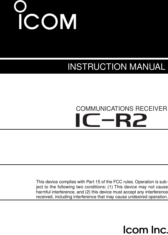
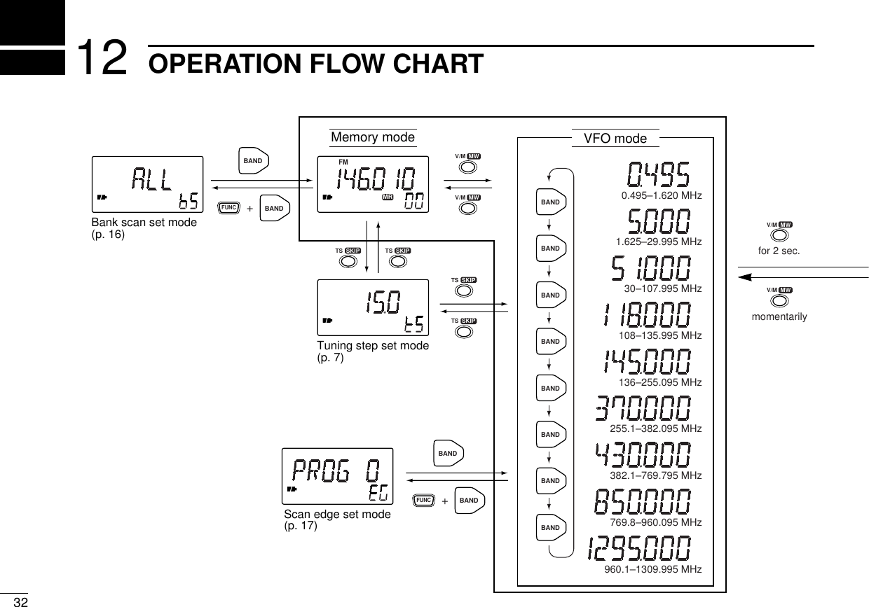
![63FREQUENCY AND CHANNEL SETTING■VFO and memory channelsThis receiver has 2 normal operating modes: VFO mode andmemory mode.VFO mode is used for setting a desired frequency within thefrequency coverage.➥Push [V/M] to select VFO mode.Memory mode is used for operation of memory channelswhich have programmed frequencies.➥Push [V/M] to select memorymode.•To program a memory, refer to p. 12.What is VFO?VFO is an abbreviation of Variable Frequency Oscillator. Fre-quencies for receiving are generated and controlled by theVFO.■Operating band selectionThe receiver can receivethe broadcast band, HFband, 50 MHz band, VHFavionics band, 144 MHzband, 300 MHz band, 400MHz band, 800 MHz band*or 1200 MHz band.➥Push [BAND] severaltimes to select the de-sired band.•When a memory channelis selected, the first pushof [BAND] selects VFOmode (and transfers thememory channel con-tents).➥Rotate [DIAL] whilepushing [BAND] to selectthe desired band.*Some frequencies can-not be received withthe U.S.A. version.FMFMMRMR“ ” appears.FM30–107.995 MHzAM108–135.995 MHz1.625–29.995 MHz0.495–1.620 MHzFM136–255.095 MHzFM255.1–382.095 MHzFM382.1–769.795 MHzFM769.8–960.095 MHzFM960.1–1309.995 MHzAMAMBANDBANDBANDBANDBANDBANDBANDBAND](https://usermanual.wiki/ICOM-orporated/IC-R2/User-Guide-5157-Page-10.png)
![■Setting a frequencyqSelect VFO mode with [V/M].wSelect the desired band with [BAND].eRotate [DIAL] to change the frequency.•The frequency changes according to the preset tuning steps. Seethe right section for selecting the tuning step.•Rotate [DIAL] while pushing [FUNC] to change the frequency in 1MHz steps (default; p. 26).The 1 MHz tuning step (dial select step) can be set to 100kHz, 1 MHz or 10 MHz tuning steps in set mode. See p. 26for details.■Setting a tuning stepTuning steps can be selected for each band, however, the tun-ing step of the broadcast band is fixed to 9 kHz steps exceptfor U.S.A. and Canada versions. The following are available.•5 kHz •6.25 kHz •10 kHz •12.5 kHz •15 kHz•20 kHz •25 kHz •30 kHz •50 kHz •100 kHzDUsing the [TS] switchqSelect VFO mode with [V/M].wSelect the desired band with[BAND].ePush [TS] to enter tuning step set-ting condition.rRotate [DIAL] to select the desired tuning step.tPush [TS] to return to normal operation.DUsing set modeqSelect VFO mode with [V/M].wSelect the desired band with [BAND].ePush [V/M] for 2 sec. to enter set mode.rRotate [DIAL] until “STEP” appears.•“STEP” disappears after 1 sec. and the previously selected tun-ing step and “tS” appear.tWhile pushing [FUNC], rotate [DIAL] to select the desiredtuning step.yPush [V/M] to exit set mode.73FREQUENCY AND CHANNEL SETTING15 kHz tuning stepFM755025755025FM755025755025[DIAL] changes the frequency according to the selected tuning step.While pushing [FUNC], [DIAL] changesthe frequency in 1 MHz steps (default).](https://usermanual.wiki/ICOM-orporated/IC-R2/User-Guide-5157-Page-11.png)
![83FREQUENCY AND CHANNEL SETTING■Selecting a memory channelqPush [V/M] to select memorymode.•“X” appears when a memorychannel is selected.wRotate [DIAL] to change the indi-cated memory channel.•Only programmed memory chan-nels can be selected.•Rotate [DIAL] while pushing [FUNC]to change the memory bank.■Lock functionThe lock function prevents accidental frequency changes andaccidental function access.➥Push [FUNC] + [(MODE)LOCK] to toggle the lock functionON and OFF.•[POWER], [VOL] and [SQL] can stillbe accessed while the lock functionis ON (default).•Accessible switches can be set to 1of 4 groups in expanded set mode.See p. 28 for details.■Attenuator functionThe attenuator prevents a desired signal from distorting whenvery strong signals are near the desired frequency or whenvery strong electric fields, such as from a broadcasting sta-tion, are near your location.The attenuator has approx. 10 dB attenuation.➥Push [FUNC] + [SQL] to toggle the attenuator function ONand OFF.FMMRSKIPFMMR132[DIAL] changes thememory channel.While pushing [FUNC],[DIAL] changes the memory bank.FM ATTAppears when the attenuator function is in use.FM“ ” appears when thelock function is in use.](https://usermanual.wiki/ICOM-orporated/IC-R2/User-Guide-5157-Page-12.png)
![94BASIC OPERATION■ReceivingMake sure charged Ni-Cd or alkaline batteries are installed.(p. 1)qPush [POWER] for 2 sec. to turn power ON.wPush [VOLY] or [VOLZ] to set the desired audio level.•The frequency display shows the volume level while setting. Seethe next page for details.eSet an operating frequency. (pgs. 6, 7)rSet the squelch level.•While pushing [SQL], rotate [DIAL].•The first click of [DIAL] indicates the current squelch level.•“LEVEL1” is loose squelch and “LEVEL9” is tight squelch.•“AUTO” indicates automatic level adjustment with a noise pulsecount system.•Push and hold [SQL] to open the squelch manually.tWhen a signal is received:➥Squelch opens and audio is emitted from the speaker.➥The S/RF indicator shows the relative signal strength.q Power switchw Set volumee Select bandr Push for setting the squelch(Push to monitor)e Set frequencyr Set the squelch level](https://usermanual.wiki/ICOM-orporated/IC-R2/User-Guide-5157-Page-13.png)
![104BASIC OPERATION■Setting volume levelThe audio level can be adjusted through 32 levels.➥Push [VOLY] or [VOLZ] to set the desired audio level.•Beep tone sounds while setting. This indicates the approximatesound level.•Pushing and holding these keys change the audio level continu-ously.•The frequency display shows the volume level while setting.■Setting squelch levelThe squelch circuit mutes the received audio signal depend-ing on the signal strength. The receiver has 9 squelch levels,a continuously open setting and an automatic squelch setting.➥While pushing [SQL], rotate the[DIAL] to select the squelch level.•The first click of [DIAL] indicates thecurrent squelch level.•“LEVEL1” is loose squelch and“LEVEL9” is tight squelch.•“AUTO” indicates automatic level ad-justment with a noise pulse countsystem.•“OPEN” indicates continuously opensetting.■Monitor functionThis function is used to listen to weak signals or to open thetone squelch manually.➥Push and hold [SQL] to monitor the operating frequency.The [SQL] switch can be set to ‘sticky’ operation in ex-panded set mode. (p. 27)AUDIO LEVELINDICATIONMin. setting (no audio):Initial setting:::Max. settingAutomatic squelchMaximum level](https://usermanual.wiki/ICOM-orporated/IC-R2/User-Guide-5157-Page-14.png)
![114BASIC OPERATION■Receive mode selectionReceive modes are determined by the physical properties ofthe radio signals.The receiver has 3 receive modes: FM, AMand WFM modes. The mode selection is stored independentlyin each band and memory channels.Typically, AM mode is used for the AM broadcast stations(0.495–1.620 MHz) and air band (118–135.995 MHz), andWFM is used for FM broadcast stations (76–107.9 MHz).➥Push [MODE] one or more times to select the desired re-ceive mode.■Display backlightingThe receiver has display backlighting with a 5 sec. timer fornighttime operation. The display backlighting can be turnedON continuously or turned OFF, if desired.➥Push any switch except [FUNC]; or, rotate [DIAL] to turn thebacklighting ON.•When auto backlighting is set, the backlighting will automaticallyturn OFF when switches and [DIAL] have not been operated for 5sec.DSetting the backlighting conditionqPush [V/M] for 2 sec. to enter setmode.wRotate [DIAL] until “LIGHT” ap-pears.•“LIGHT” disappears after 1 sec. andthe previously selected backlightingtimer and “LI” appear.eWhile pushing [FUNC], rotate[DIAL] to select the desired back-lighting condition.rPush [V/M] to exit set mode.Automatic backlightingBacklighting set modeContinuously OFFWFMFM AMAM modeWFM modeFM mode](https://usermanual.wiki/ICOM-orporated/IC-R2/User-Guide-5157-Page-15.png)
![125MEMORY CHANNELS■GeneralThe receiver has 400 memory channels in 8 banks for stor-age of often-used frequencies.DMemory channel contentsThe following information can be programmed into memorychannels:•Operating frequency (p. 7)•Receive mode (p. 11)•Tuning step (p. 7)•Duplex direction (DUP or –DUP) with an offset frequency(p. 24)•Tone squelch ON/OFF (p. 22)•Tone squelch frequency (p. 22)•Scan skip setting (p. 18)■Programming during selectionqSelect VFO mode with [V/M].wSet the desired frequency:➥Select the desired band with [BAND].➥Set the frequency using [DIAL].➥Set other data (e.g. offset frequency, duplex direction,tone squelch frequency, etc.), if required.ePush [FUNC] + [(V/M)MW] momentarily to indicate memorychannels.•Do not hold [FUNC] + [(V/M)MW] for more than 0.5 sec., other-wise the previously selected memory channel will be overwritten.rRotate [DIAL] to select the desired channel.•VFO (VF), as well as regular memory channels, can be pro-grammed in this way.•Rotate [DIAL] while pushing [FUNC] to select a memory bank,programmed scan edge channel or VFO.tPush [FUNC] + [(V/M)MW] for 1 sec. to program.•Keep pushing for 2 sec. or more to automatically select the nextmemory channel, if desired.FM DUPTSQL FM DUPTSQLFMMR MR1momentarilyblank channelfor 2 sec.+FUNC+FUNCfor bankselection for CHselection+FUNCV/M MW V/M MW[EXAMPLE]: Programming ch 40 of memory bank 5 during selection.](https://usermanual.wiki/ICOM-orporated/IC-R2/User-Guide-5157-Page-16.png)
![135MEMORY CHANNELS■Programming after selectionqSelect memory mode with [V/M].wSet the memory channel to be programmed with [DIAL].•Rotate [DIAL] while pushing [FUNC] to select a memory bank orprogrammed scan edge channel.•Non-programmed channels cannot be selected.ePush [V/M] to select VFO mode.rSet the desired frequency:➥Select the desired band with [BAND].➥Set the frequency using [DIAL].➥Set other data (e.g. offset frequency, duplex direction,tone squelch frequency, etc.), if required.tPush [FUNC] + [(V/M)MW] for 1 sec. to program the se-lected channel.•Keep pushing for 2 sec. or more to automatically select the nextmemory channel, if desired.■Transferring memorycontents to another memoryqSelect memory mode with [V/M].wSelect the memory channel to transfer with [DIAL].•Rotate [DIAL] while pushing [FUNC] to select a memory bank orprogrammed scan edge channel.ePush [FUNC] + [(V/M)MW] momentarily to indicate memorychannels.•Do not hold [FUNC] + [(V/M)MW] for more than 0.5 sec., other-wise the memory channel contents will be transferred to VFO.rRotate [DIAL] to select the channel to transfer to.•Rotate [DIAL] while pushing [FUNC] to select a memory bank orprogrammed scan edge channel.•VFO (VF), as well as regular memory channels, can be trans-ferred in this way.tPush [FUNC] + [(V/M)MW] for 2 sec. to transfer.MRFMMRFMMRFMMRV/M MWmomentarilySelect memorychannelfor 1 sec.+FUNC+FUNCblank channelV/M MWV/M MW[EXAMPLE]: Transferring memory channel 3 (memory bank 0) to 20 (memory bank 0).](https://usermanual.wiki/ICOM-orporated/IC-R2/User-Guide-5157-Page-17.png)
![145MEMORY CHANNELS■Memory bank selectionThe receiver has 400 memory channels in 8 banks for stor-age of often-used frequencies.qSelect memory mode with [V/M].wRotate [DIAL] while pushing [FUNC] to select the desiredmemory banks.•“1” – “3” indicate memory banks 1 to 3; “♦” indicates memorybank 4; “♦1” – “♦3” indicate memory banks 5 to 7; no bank indi-cator indicates memory bank 0.eRotate [DIAL] to select the desired memory channel.■Memory clearUnwanted memory channels can be cleared (erased). Beforeclearing a memory channel make sure it is no longer neededas cleared memories cannot be recalled.qSelect memory mode with [V/M].wSet the memory channel to be cleared with [DIAL].•Rotate [DIAL] while pushing [FUNC] to select a memory bank orprogrammed scan edge channel.eSelect VFO mode with [V/M] and push [FUNC] + [(V/M)MW]momentarily to indicate the selected memory channel.•Do not hold [FUNC] + [(V/M)MW] for more than 0.5 sec., other-wise the selected memory channel will be overwritten.rPush [FUNC] + [(MODE)LOCK] for 2 sec. to clear the se-lected memory channel.•3 beeps sound, then the frequency is cleared.tPush [V/M] to return to VFO mode.MRFMMRFMMRFMSelect memorychannelfor 2 sec.+FUNCmomentarily+FUNCV/M MW V/M MWV/M MWV/M MWMODE LOCK[EXAMPLE]: Clearing memory channel 3 (memory bank 0).FMMRFMMR1FMMR3Memory bank 0 Memory bank 1 Memory bank 7](https://usermanual.wiki/ICOM-orporated/IC-R2/User-Guide-5157-Page-18.png)
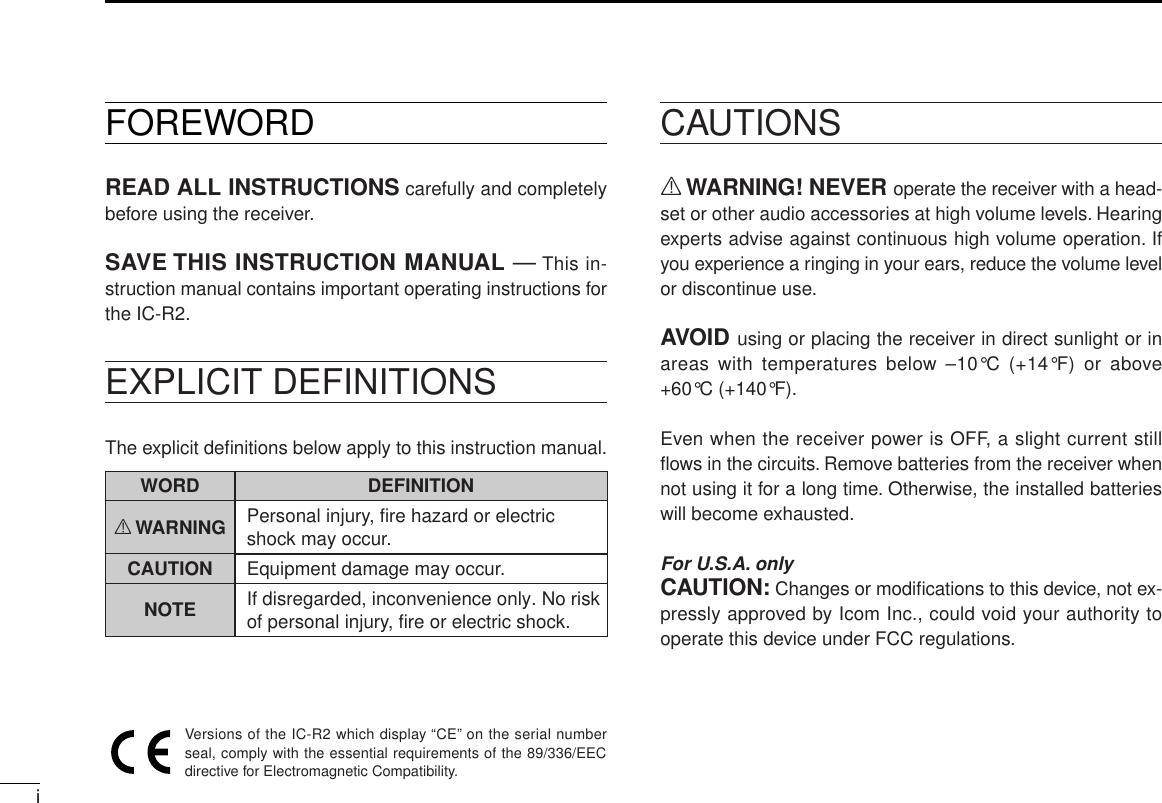
![156SCAN OPERATION■Scan types Up to 25 programmed scan ranges, full scan, band scan andmemory bank scan provide scanning versatility. Each scancan have skip channels programmed.FULL SCAN (p. 16) Repeatedly scans all fre-quencies over the entire receiver range.U.S.A. version cannot receive some frequencies.PROGRAMMED SCAN(p. 16)Repeatedly scans between two user-programmed fre-quencies. Used for checking for frequencies within a specified range such as repeater output frequencies, etc.495 kHz 1309.995 MHzScanJumpSELECTED BAND SCAN (p. 16) Repeatedly scans all fre-quencies over the entire selected band.ScanJumpScanJumpScan edgesMEMORY SKIP FUNCTION(p. 18) Skips unwanted memory channels that inconvenient-ly stop scanning. Skip channels can be toggled ON and OFF by pushing [FUNC] + [(TS) SKIP] in memory mode.Not yetprogrammedch 0ch 1 ch 2 ch 3ch 4ch 5ch 6ch 49Band edge or scan edgeBand edge or scan edgeFREQUENCY SKIP FUNCTION (p. 19) Skips unwanted frequen-cies that inconveniently stop scanning. This func-tion can be turned ON and OFF in frequency skip func-tion set mode. ([FUNC] + [(TS) SKIP])MEMORY (BANK) SCAN (p. 16) Repeatedly scans memory channels except skip chan-nels within all programmed channels or within a memo-ry bank (0–7).Not yetprogrammedSKIPch 0ch 1 ch 2 ch 3ch 4ch 5ch 6ch 49BandedgeBandedgeBandedgeBandedgeJumpSkip SkipScan](https://usermanual.wiki/ICOM-orporated/IC-R2/User-Guide-5157-Page-19.png)
![166SCAN OPERATION■Full/band/programmed scanqSelect VFO mode with [V/M].wMake sure the squelch is set to the threshold point.•Select automatic squelch (AUTO) or a level (1–9) where thenoise is just muted. (p. 10)eSelect the desired scan range, if desired.➥Select scan edges in scan edge set mode:“ALL” for full scan, “BAND” for band scan or “PROG 0”–“PROG24” for programmed scan. (see the next page)rPush [FUNC] + [Y] or [Z] momentarily to start the scan.•Decimal point flashes while scanning.•“P SKIP” flashes when the frequency skip function is turned ON.(p. 19)•“0P”–“24P” flash to indicate which pair of scan edges is beingscanned.•To change the scanning direction, rotate [DIAL].•If the pocket beep function is activated, the receiver automaticallyselects the tone squelch function when a scan starts.tTo stop the scan, push [FUNC] + [Y] or [Z] again.If the same frequencies are programmed into a pair ofscan edges, programmed scan does not start.For programmed scan, scan edges must be programmedin advance. Program scan edges in the same manner ofprogramming a memory channel and select a scan edge.(p. 17)■Memory (bank) scanqSelect memory mode with [V/M].wMake sure the squelch is set to the threshold point.•Select automatic squelch (AUTO) or a level (1–9) where thenoise is just muted. (p. 10)eTurn the memory bank scan ON or OFF in the memoryscan set mode, if desired.•See below for details.rPush [FUNC] + [Y] or [Z] momentarily to start the memory(bank) scan.•Decimal point flashes while scanning.•To change the scanning direction, rotate [DIAL].•If the pocket beep function is activated, the receiver automaticallyselects the tone squelch function when a scan starts.tTo stop the scan, push [FUNC] + [Y] or [Z] again.DMemory bank selectionqSelect memory mode with [V/M].wWhile pushing [FUNC], push [BAND] to enter memoryscan set mode.eRotate [DIAL] to select the memory bank scan ON or OFF.•“ALL” indicates all memory banks arescanned (memory bank scan OFF);“BANK” indicates memory bank scanis turned ON.rPush [BAND] to exit memory scanset mode.Bank scan ON](https://usermanual.wiki/ICOM-orporated/IC-R2/User-Guide-5157-Page-20.png)
![176SCAN OPERATION■Selecting scan edgesThe scanning range can be set to all frequencies (full scan), aselected band or between two user-programmed frequencies(programmed scan).The programmed scan edges can be programmed in thesame manner as programming regular memory channels.Program the desired scan edge frequencies in a pair ofprogrammed scan edge channels in advance. (pgs. 12, 13)qSelect VFO mode with [V/M].wWhile pushing [FUNC], push [BAND] to enter band edgeset mode.eRotate [DIAL] to select the desired scan edge.•“ALL” for full scan, “BAND” for band scan or “PROG 0” –“PROG24” for programmed scan.rPush [BAND] to exit band edge set mode; or push [FUNC]+ [Y] or [Z] momentarily to start the programmed scanusing the selected edges.Full scan Band scan Programmed scan 24(Scan edge channels24A and 24b)](https://usermanual.wiki/ICOM-orporated/IC-R2/User-Guide-5157-Page-21.png)
![186SCAN OPERATION■Skip channel settingMemory channels can be set to be skipped for memory skipscan. In addition, memory channels can be set to be skippedfor both memory skip scan and frequency skip scan. Theseare useful to speedup the scan interval.qSelect memory mode with [V/M].wRotate [DIAL] to select a memory channel to be pro-grammed as a skip channel.eWhile pushing [FUNC], push [(TS)SKIP] one or more timesto select a condition.•No indication : channel will not be skipped.•“SKIP” appears : channel skipped during memory scan.•“P SKIP” appears : channel skipped during memory scan; fre-quency skipped during other scans.The frequency skip function is effective when the fre-quency skip function (P SCAN) is turned ON. See the nextpage for details.■Scan resume conditionDSetting the scan pause timeThe scan pauses when receiving signals according to thescan pause time. It can be set from 2–20 sec. or unlimited.qPush [V/M] for 2 sec. to enter expanded set mode.wRotate [DIAL] until “PAUSE” appears.•Turn the expanded set mode ON for selection. (p. 25)eWhile pushing [FUNC], rotate [DIAL] to select the condition.•“2SEC”–“20SEC”: scan pauses for 2–20 sec. on a received sig-nal.•“HOLD”: scan pauses on a received signal until it disappears.rPush [V/M] to exit set mode.DSetting the scan resume timeThe scan restarts after a signal disappears according to theresume time. It can be set from 0–5 sec. or unlimited.qPush [V/M] for 2 sec. to enter expanded set mode.wRotate [DIAL] until “RESUME” appears.•Turn the expanded set mode ON for selection. (p. 25)eWhile pushing [FUNC], rotate [DIAL] to select condition.•“1SEC”–“5SEC”: scan restarts 1–5 sec. after the signal disap-pears.•“0SEC”: scan restarts immediately after the signal disappears.•“HOLD”: scan restarts by rotating [DIAL] only.rPush [V/M] to exit set mode.FMMRPSKIPFMMRSKIPFMMRSkip channelNon-skip channelSkip channel and frequency skip channel](https://usermanual.wiki/ICOM-orporated/IC-R2/User-Guide-5157-Page-22.png)
![196SCAN OPERATION■Frequency skip functionDProgramming a skip frequencyUnwanted frequencies can be skipped and programmed asskip channels when full scan, band scan or programmed scanis pausing.qStart full scan, band scan or programmed scan. (p. 16)wWhile receiving an unwanted signal and scan pauses,push [FUNC] + [(TS)SKIP] for 2 sec. to program the re-ceived frequency as a skip frequency.•The receiver emits 3 beeps and the scan resumes.•Non-programmed memory channels (blank channels) are usedfor skip frequency programming in reverse sequence.•To scan the skip frequency after programming, cancel the skipinformation (p. 18) or clear the memory channel (p. 14).DFrequency skip function ON/OFFThe frequency skip function can be turned OFF. In this case,the frequencies will not be skipped even if skip information isprogrammed and “P SKIP” does not appear.qSelect VFO mode with [V/M].wPush [FUNC] + [(TS) SKIP] to toggle the frequency skipfunction ON or OFF.•“P SKIP” appears when the function is turned ON.FMPSKIPFMThe frequency skipfunction is OFF. The frequency skipfunction is ON.FMPSKIPBUSY5FMPSKIPBUSY53Indication while programmingIndication while pausing](https://usermanual.wiki/ICOM-orporated/IC-R2/User-Guide-5157-Page-23.png)
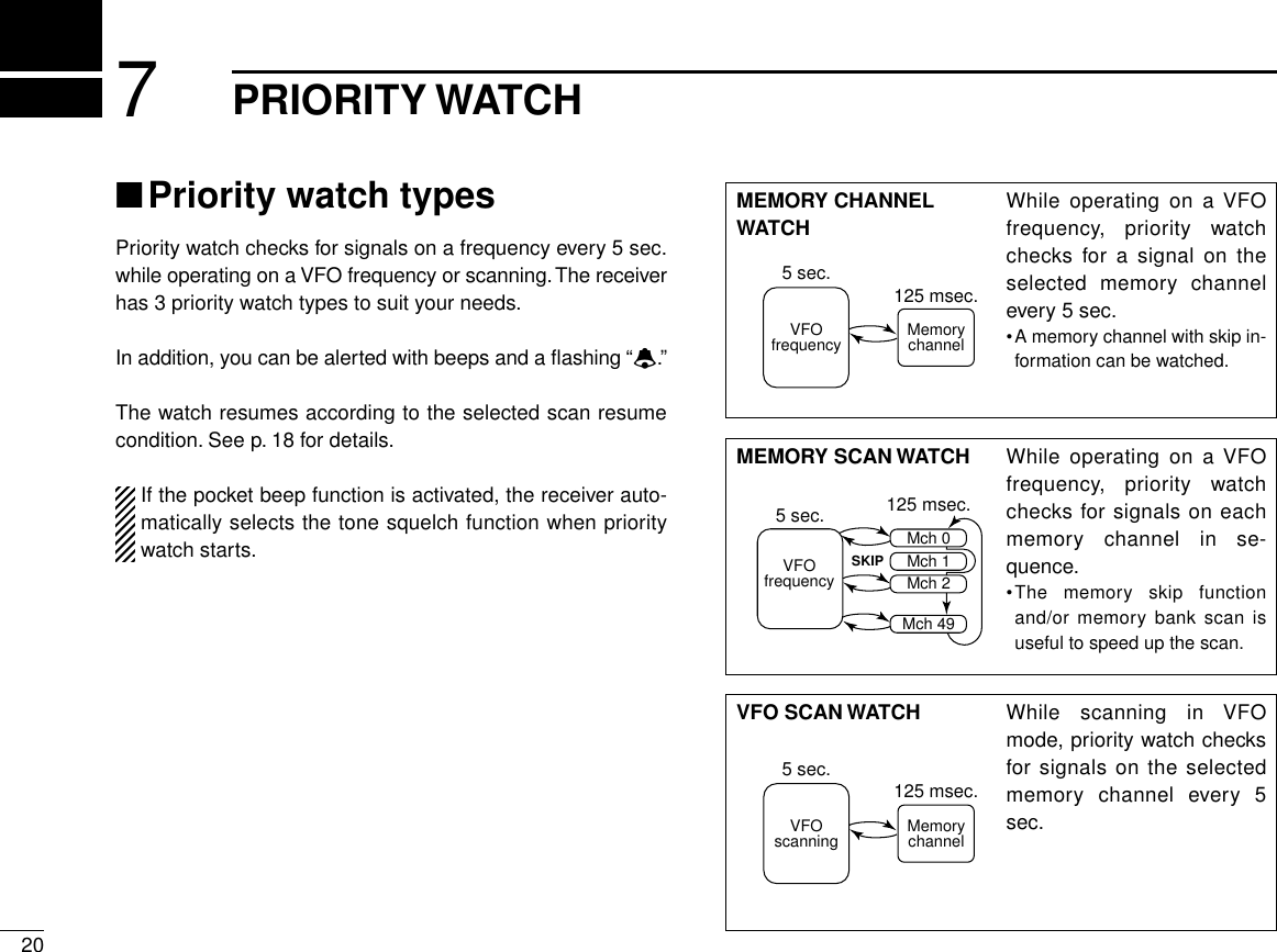
![217PRIORITY WATCH■Priority watch operationDMemory channel watch and memory scanwatchqSelect VFO mode; then, set an operating frequency.wSet the watching channel(s).For memory channel watch:Select the desired memory channel.For memory scan watch:Select memory mode; then, push [FUNC] + [Y] or [Z] mo-mentarily to start memory scan.ePush [V/M] for 2 sec. to enter set mode.rRotate [DIAL] until “PRIO” appears.•“PRIO” disappears after 1 sec. and “OFF” and “PR” appear.tWhile pushing [FUNC], rotate [DIAL] to select prioritywatch ON or priority watch ON with alert.yPush [V/M] to exit set mode and start the watch.•The receiver checks the memory channel frequency every 5 sec.•The watch resumes according to the selected scan resume con-dition. (p. 18)uPush [V/M] while the displayshows the VFO frequency to stopthe watch.DVFO scan watchqSelect the desired memory channel to be watched.wPush [V/M] to select VFO mode.ePush [FUNC] + [Y] or [Z] momentarily to start full scan,band scan or programmed scan. (p. 16)rPush [V/M] for 2 sec. to enter set mode.tRotate [DIAL] until “PRIO” appears.•“PRIO” disappears after 1 sec. and“OFF” and “PR” appear.yWhile pushing [FUNC], rotate[DIAL] to select priority watch ONor priority watch ON with alert.uPush [V/M] to exit set mode andstart the watch.•The receiver checks the memorychannel frequency every 5 sec.•The watch resumes according to theselected scan resume condition. (p.18)iPush [V/M] while the displayshows the VFO frequency to stopthe watch.Priority watch is ON.Priority watch set modePriority watch withalert is ON.PRIOFMMRWhile pausing on thememory channel, “PRIO”flashes.](https://usermanual.wiki/ICOM-orporated/IC-R2/User-Guide-5157-Page-25.png)
![228SUBAUDIBLE TONE OPERATION■Tone squelch operationDOperationThe tone squelch opens only when receiving a signal con-taining a matching subaudible tone. You can silently wait forcalls from group members using the same tone in an ama-teur band.qSet the operating frequency.wSet the desired subaudible tone inexpanded set mode.•See right for programming.ePush [V/M] for 2 sec. to enter ex-panded set mode.rRotate [DIAL] until “TSQL” ap-pears.•Turn the expanded set mode ON forselection. (p. 25)•“TSQL” disappears after 1 sec. and “tO” appears.tWhile pushing [FUNC], rotate [DIAL] to select “TSQL.”yPush [V/M] to exit set mode and start the tone squelch.uWhen the received signal includes a matching tone,squelch opens and the signal can be heard.•When the received signal’s tone does not match, tone squelchdoes not open, however, the S-indicator shows signal strength.•To open the squelch manually, push and hold [SQL].iTo cancel the tone squelch, repeat steps e–yas de-scribed above and select “OFF” in step t.DSetting subaudible tones for tone squelchoperationqSelect VFO mode or desired memory channel to be pro-grammed.wPush [V/M] for 2 sec. to enter expanded set mode.eRotate [DIAL] until “TONE” appears.•Turn the expanded set mode ON for selection. (p. 25)•“TONE” disappears after 1 sec. and “Ct” appears.rWhile pushing [FUNC], rotate [DIAL] to select a subaudibletone.•Each operating band and each memory channel have indepen-dent settings.tPush [V/M] to exit set mode.•Available subaudible tone frequencies (unit: Hz)➲CONVENIENTStore subaudible tone frequencies and tone squelch ON/OFFsettings in memories for easy recall.Tone squelch is ON.Tone function set mode67.069.371.974.477.079.782.585.488.591.594.897.4100.0103.5107.2110.9114.8118.8123.0127.3131.8136.5141.3146.2151.4156.7159.8162.2165.5167.9171.3173.8177.3179.9183.5186.2189.9192.8196.6199.5203.5206.5210.7218.1225.7229.1233.6241.8250.3254.1](https://usermanual.wiki/ICOM-orporated/IC-R2/User-Guide-5157-Page-26.png)
![238SUBAUDIBLE TONE OPERATION■Pocket beep operationThis function uses subaudible tones for calling and can beused as a “common pager” to inform you that someone hascalled using the same tone in an amateur band while youwere away from the receiver.DWaiting for a call from a specific stationqSet the operating frequency.wSet the desired tone squelch tone in expanded set mode.•See the previous page for programming information.ePush [V/M] for 2 sec. to enter expanded set mode.rRotate [DIAL] until “TSQL” appears.•Turn the expanded set mode ON for selection. (p. 25)•“TSQL” disappears after 1 sec. and “tO” appears.tWhile pushing [FUNC], rotate [DIAL] to select “P BEEP.”yPush [V/M] to exit set mode and start the pocket beep.•“TSQL ë” appears in the function display.uWhen a signal with the correct tone is received, the re-ceiver emits beep tones for 30 sec. and flashes “ë.”iPush [V/M] to stop the beeps and flashing.•Tone squelch is automatically selected.The receiver has 50 tone frequencies and consequentlytheir spacing is narrow compared with units having 38tones. Therefore, some tone frequencies may receive in-terference from adjacent tone frequencies.■Tone scanThe receiver can detect the subaudible tone frequency in areceived signal. By monitoring a signal that is being transmit-ted on a frequency, you can check the tone frequency re-quired to access the repeater or to open the tone squelch.qSet the desired frequency or memory channel to bechecked for a tone frequency.wPush [FUNC] + [Y] or [Z] for 2 sec. to start the tone scan.•To change the scanning direction, rotate [DIAL].eWhen the tone frequency is decoded, the set mode con-tents are programmed with the tone frequency.•The tone scan pauses when a tone frequency is detected.•The decoded tone frequency is used for the tone squelch fre-quency.•“Ct” appears during tone scan.rPush [FUNC] + [Y] or [Z] to stop the scan.T“Ct” appears during tone scan.Tone frequencies flash as they are scanned.](https://usermanual.wiki/ICOM-orporated/IC-R2/User-Guide-5157-Page-27.png)
![249DUPLEX OPERATIONDuplex communication uses 2 different frequencies for trans-mitting and receiving. Generally, duplex is used in communi-cation through a repeater, some utility communications, etc.During duplex operation, the transmit station frequency isshifted from the receive station frequency by the offset fre-quency. Repeater information (offset frequency and shift di-rection) can be programmed into memory channels. (p. 12)This function is not available in the broadcast band (0.495–1.620 MHz) except for U.S.A. and Canada versions.qSet the receive station frequency (repeater output fre-quency).wSet the shift direction and offset of the transmit station fre-quency as described below.ePush and hold [SQL] to monitor the transmit station fre-quency (repeater input frequency) directly.DDuplex shift directionqPush [V/M] for 2 sec. to enter expanded set mode.wRotate [DIAL] until “DUP” appears.•Turn the expanded set mode ON forselection. (p. 25)•“DUP” disappears after 1 sec. and“dP” appears.eWhile pushing [FUNC], rotate[DIAL] to select “–DUP” or “+DUP.”•“–DUP” or “+DUP” indicates the transmit station frequency forminus shift or plus shift, respectively.rPush [V/M] to exit set mode.DOffset frequencyDuring duplex operation, the transmit station frequency isshifted from the receive station frequency by an amount de-termined by the offset frequency.qSelect VFO mode or desired memory channel to be pro-grammed.wPush [V/M] for 2 sec. to enter expanded set mode.eRotate [DIAL] until “OFFSET” appears.•Turn the expanded set mode ON for selection. (p. 25)•“OFFSET” disappears after 1 sec. and “OW” appears.rWhile pushing [FUNC], rotate [DIAL] to set the desired off-set.•The offset frequency changes according to the selected tuningstep.tPush [V/M] to exit set mode.Offset frequency set mode 0.6 MHz (600 kHz) offsetMinus shift](https://usermanual.wiki/ICOM-orporated/IC-R2/User-Guide-5157-Page-28.png)
![2510OTHER FUNCTIONS■Set modeSet mode is used for programming infrequently changed val-ues or conditions of functions.In addition, this receiver has an expanded set mode which isused for programming additional infrequently changed valuesor conditions of functions. When turning OFF the expandedset mode, only a quarter of the set mode items are displayedfor simpler operation.DExpanded set mode ON/OFFqPush [V/M] for 2 sec. to enter set mode.wRotate [DIAL] clockwise until “EXPAND” appears.•“EXPAND” disappears after 1 sec. and “EX” appears.eWhile pushing [FUNC], rotate [DIAL] to turn the expandedset mode ON or OFF.rPush [V/M] to exit set mode or rotate [DIAL] to select a setmode item.DSet mode itemsE: Appears when expanded set mode is ON.B: Does not appear within the broadcast band (0.495–1.620 MHz)except for U.S.A. and Canada versions.Tuning step(p. 7)Dial select step(p. 26)Tone squelch(p. 22)Tone squelch tone (p. 22)Duplex direction(p. 24)Offset frequency(p. 24)Scan resumetime (p. 18)Scan pausetime (p. 18)Priority watch(p. 21)Confirmation beep (p. 26)Backlighting(p. 11)Auto power OFF(p. 27)Power save(p. 26)Monitor switchaction (p. 27)Dial speed(p. 28)Lock function effect (p. 28)Channel indicationmode (p. 29)EEEEEEEEEEBBBBEEExpanded setmode (p. 25)Expanded set mode setting Expanded set mode ON](https://usermanual.wiki/ICOM-orporated/IC-R2/User-Guide-5157-Page-29.png)
![2610 OTHER FUNCTIONS■Dial select stepThis receiver has a 1 MHz tuning step for quick frequency set-ting. This dial select step can be set to 100 kHz, 1 MHz or 10MHz steps, as desired.This function is not available to the broadcast band (0.495–1.620 MHz) except for U.S.A. and Canada versions.DSetting dial select stepqSelect VFO mode with [V/M].wPush [V/M] for 2 sec. to enter set mode.eRotate [DIAL] until “D SEL” appears.•“D SEL” disappears after 1 sec. and “dS” appears.rWhile pushing [FUNC], rotate [DIAL] to select the desireddial select step.•100 kHz, 1 MHz and 10 MHz steps can be selected.tPush [V/M] to exit set mode.■Beep tonesThe confirmation beep tones, which sound each time a switchis pushed, can be turned ON or OFF, as desired.qPush [V/M] for 2 sec. to enter set mode.wRotate [DIAL] until “BEEP” appears.•“BEEP” disappears after 1 sec. and “bE” appears.eWhile pushing [FUNC], rotate [DIAL] to turn the confirma-tion beep ON or OFF.rPush [V/M] to exit set mode.■Power saverThe power saver function reduces the current drain to con-serve battery power.qPush [V/M] for 2 sec. to enter expanded set mode.wRotate [DIAL] until “P SAVE” appears.•Turn the expanded set mode ON for selection. (p. 25)•“P SAVE” disappears after 1 sec. and “PS” appears.eWhile pushing [FUNC], rotate [DIAL] to turn the powersaver ON (AUTO) or OFF.rPush [V/M] to exit set mode.1 MHz step100 kHz step 10 MHz step](https://usermanual.wiki/ICOM-orporated/IC-R2/User-Guide-5157-Page-30.png)
![2710OTHER FUNCTIONS■Auto power-off functionThe receiver can be set to automatically turn OFF after aspecified period in which no switch is pushed.120 min., 90 min., 60 min., 30 min. and OFF can be speci-fied. The specified period is retained even when the receiveris turned OFF by the auto power-off function. To cancel thefunction, select “OFF” in step ebelow.qPush [V/M] for 2 sec. to enter expanded set mode.wRotate [DIAL] until “AP OFF” appears.•Turn the expanded set mode ON for selection. (p. 25)•“AP OFF” disappears after 1 sec. and “AO” appears.eWhile pushing [FUNC], rotate [DIAL] to select the desiredtime or to turn the function OFF.rPush [V/M] to exit set mode.■Monitor switch actionThe monitor switch can be set as a ‘sticky’ switch.When set tothe sticky condition, each push of [SQL] toggles the monitorfunction on and off.qPush [V/M] for 2 sec. to enter expanded set mode.wRotate [DIAL] until “MONI” appears.•Turn the expanded set mode ON for selection. (p. 25)•“MONI” disappears after 1 sec. and “mO” appears.eWhile pushing [FUNC], rotate [DIAL] to set the monitorswitch to sticky (HOLD) or normal (PUSH).rPush [V/M] to exit set mode.60 min. auto power-offAuto power off set mode Auto power-off isturned OFF.‘Sticky’ actionMonitor switch function set mode ‘Normal’ action](https://usermanual.wiki/ICOM-orporated/IC-R2/User-Guide-5157-Page-31.png)
![2810 OTHER FUNCTIONS■Dial speed accelerationThe dial speed acceleration automatically speeds up the tun-ing dial speed when rotating the [DIAL] rapidly.qPush [V/M] for 2 sec. to enter expanded set mode.wRotate [DIAL] until “SPEED” appears.•Turn the expanded set mode ON for selection. (p. 25)•“SPEED” disappears after 1 sec. and “SP” appears.eWhile pushing [FUNC], rotate [DIAL] to set the dial speedacceleration ON or OFF.rPush [V/M] to exit set mode.■Lock function effectThe lock function prevents accidental frequency changes andaccidental function access.While the lock function is ON, [POWER], [VOL] and [SQL] canstill be accessed. Accessible switches can be set to 1 of 4groups in expanded set mode.qPush [V/M] for 2 sec. to enter expanded set mode.wRotate [DIAL] until “LOCK” appears.•Turn the expanded set mode ON for selection. (p. 25)•“LOCK” disappears after 1 sec. and “Lk” appears.eWhile pushing [FUNC], rotate [DIAL] to select the acces-sible switches.•“NORMAL” :[POWER], [VOL] and [SQL] are accessible.•“NO SQL” :[POWER] and [SQL] are accessible.•“NO VOL” :[POWER] and [VOL] are accessible.•“ALL” :[POWER] is accessible.rPush [V/M] to exit set mode.Dial speed accelerationset modeDial speed acceleration ON Dial speed acceleration OFFLock function effectset mode [POWER], [VOL] and [SQL] areaccessible.[POWER] is accessible.](https://usermanual.wiki/ICOM-orporated/IC-R2/User-Guide-5157-Page-32.png)
![2910OTHER FUNCTIONS■Channel indication modeChannel indication mode is used to simplify operation. In thismode only pre-programmed memory channel numbers aredisplayed and functions are limited ([POWER], [SQL], [VOL],[LOCK], scanning and the tuning dial are functional).qSelect memory mode with [V/M].wPush [V/M] for 2 sec. to enter expanded set mode.eRotate [DIAL] until “CH” appears.•Turn the expanded set mode ON for selection. (p. 25)rWhile pushing [FUNC], rotate [DIAL] to turn the channelindication ON or OFF.tPush [V/M] to exit set mode.•To return to normal indication, turn this function OFF instep rabove.•Frequencies must be programmed into memory channelsin advance.■Cloning functionThe IC-R2 has receiver-to-receiver data cloning capability.This function is useful when you want to copy all of the pro-grammed contents from one IC-R2 to another. An optionalOPC-474 CLONING CABLE is required.The optional CS-R2 CLONING SOFTWARE and the optionalOPC-478 CLONING CABLE are available to clone and editcontents using a PC.qWhile pushing [TS], [V/M] and [Y], push [POWER] for 1sec. to enter cloning mode.•“CLONE” appears.wConnect an optional OPC-474 between both [SP] jacks.ePush [SQL] on the “mas-ter” receiver (receiver-to-receiver cloning only).•“CL OUT” appears and thesignal indicator shows thatcloning is taking place.FMChannel indicationmode set mode Channel indicationmode ON Channel indicationmode example(Memory ch 49 ofmemory bank 7)OPC-474](https://usermanual.wiki/ICOM-orporated/IC-R2/User-Guide-5157-Page-33.png)
![3010 OTHER FUNCTIONS■Partial resetIf you want to initialize the operating conditions (VFO fre-quency, VFO settings, set mode contents) without clearing thememory contents, a partial resetting function is available forthe receiver.➥While pushing [FUNC] and [V/M], turn power ON to par-tially reset the receiver.■All resetReset the CPU before operating the receiver for the first time,or when the internal CPU malfunctions.➥While pushing [FUNC], [BAND] and [V/M], turn power ONto reset the CPU.•“CLEAR” appears when resetting the CPU.CAUTION:Resetting the CPU returns all programmedcontents to their default settings.](https://usermanual.wiki/ICOM-orporated/IC-R2/User-Guide-5157-Page-34.png)
![3111TROUBLESHOOTINGPROBLEM POSSIBLE CAUSE SOLUTION REF.No power comes ON. •The batteries are exhausted.•The battery polarity is reversed.•Replace the batteries.•Check the battery polarity.p. 1p. 1No sound comes from thespeaker.•Volume level is too low.•Different tone is selected with tone squelch.•Push [VOLY] to obtain a suitable level.•Check the tone using tone scan.p. 10p. 23Frequency cannot be set. •The lock function is activated.•Channel indication mode is selected.•Push [FUNC] + [(MODE)LOCK] to cancel the function.•Turn the channel indication mode OFF in set mode.p. 8p. 29No beeps sound. •Beep tones are turned OFF. •Turn beep tones ON in set mode. p. 26Receive audio isdistorted.•The operating mode is not selected correctly. •Select a suitable operating mode in set mode. p. 11Desired set mode itemcannot be selected.•The desired set mode item is in expanded setmode.•Some set mode items cannot be selected inthe broadcast band.•Turn the expanded set mode ON.•Choose a band other than the broadcast band.p. 25p. 25If your receiver seems to be malfunctioning, please check thefollowing points before sending it to a service center.](https://usermanual.wiki/ICOM-orporated/IC-R2/User-Guide-5157-Page-35.png)
![3312OPERATION FLOW CHARTTSQLBacklighting(p. 11)Set mode Expanded set modeB Tuning step(p. 7)B Tuning step (p. 7)B Dial select step (p. 26)B Dial select step (p. 26)Tone squelch(p. 22)Tone squelchtone (p. 22)B Duplex direction (p. 24)B Offset frequency(p. 24)Scan resumetime (p. 18)Scan pausetime (p. 18)Priority watch(p. 21)Priority watch (p. 21)Confirmation beep (p. 26)Confirmation beep (p. 26)Backlighting (p. 11)Auto power OFF (p. 27)Power save(p. 26)Monitor switchaction (p. 27)Dial speed(p. 28)Lock function effect (p. 28)Channel indication mode (p. 29)Expanded setmode (p. 25)Expanded set mode (p. 25)B: Does not appear within the broadcast band (0.495 – 1.620 MHz).Displays for set and ex-panded set modes showthe default settings (ex-cept the expanded setmode setting).Rotate [DIAL] while push-ing [FUNC] to change theset mode condition.](https://usermanual.wiki/ICOM-orporated/IC-R2/User-Guide-5157-Page-37.png)