ICOM orporated SL-1105 Direct Sequence Wireless LAN Card User Manual
ICOM Incorporated Direct Sequence Wireless LAN Card
UserManual.wiki
>
ICOM orporated
>
SL 1105 User Manual
Win98 Manual
Navigation menu
Upload a User Manual
Namespaces
Wiki Guide
HTML
PDF
Info
Views
User Manual
Discussion / Help
Navigation
![n Document Conventions The following notational conventions are used in this manual: lThe names of utilities, applications, windows (screens)are enclosed in square brackets ({ }). lThe names of utilities, applications, windows (screens), tabs, menus, text boxes, and check boxes are enclosed in square brackets ([ ]). lThe names of and the names of command buttons within dialog boxes are enclosed in less-than and greater-than signs (<>). n Description of the setup screens in this manual The setup screens used in this manual are for the SL-1100. Please read those parts written with SL-1100 as for the SL-1105. n System Requirements Card slot:Use this LAN card with a computer having a Type ‡U PC card slot that is CardBus compliant and supports PCMCIA 2.0 (or later versions). ÜThis LAN card is designed for use with PCMCIA card slots that operate at 5.0V. Operating system:Use this LAN card with a computer running Windows 95 (OSR2 or later), Windows 98 (including the second edition), Windows NT 4.0 (Service Pack 3 or later), or Windows 2000.](https://usermanual.wiki/ICOM-orporated/SL-1105/User-Guide-129784-Page-1.png)

![3 Using in a Windows 98 Environment 3-1 Checking the PC Card Driver n Restrictions The following restrictions apply when using the SL-1105 with Windows 98: The SL-1105 will not operate unless there is an available IRQ (sharing of an IRQ is not allowed). Secure an IRQ before installing the LAN card driver. If you do not know how to secure an IRQ, consult with the manufacturer of the computer you are using. ÜBefore the wireless LAN card driver can be installed, the 32-bit PC card driver must be installed correctly. n Checking the 32-bit PC card driver 1. Boot up the computer with which you will use the SL-1105. 2. Click <Start>and select [Control Panel] from the <Settings> menu. 3. Click the [System] icon on the {Control Panel} screen. 4. Select the [Performance] tab. Make sure {32-bit} is shown next to [PC Cards (PCMCIA)]. Ü If {MS-DOS compatible mode} or {Not installed} is shown, install the 32-bit PC card driver for Windows 98.](https://usermanual.wiki/ICOM-orporated/SL-1105/User-Guide-129784-Page-10.png)
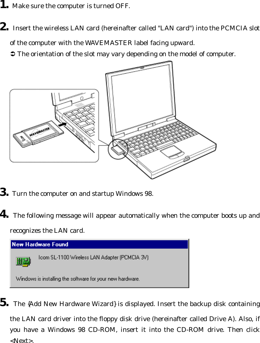
![5. Click <OK> and close the {System Properties} screen. 3 Using in a Windows 98 Environment 3-2 Installing the LAN Card Driver Install the driver using the LAN Card Utility Software disks. [IMPORTANT] Make backup copies of the {SL-1105 LAN Card Utility Software} disks and use the backup disks for the operations described in this manual.](https://usermanual.wiki/ICOM-orporated/SL-1105/User-Guide-129784-Page-11.png)
![6. Select [Search for the optimum driver for the new device (Recommended)] and click <Next>. 7. The screen shown below is displayed. Select [Specify location] and enter the name of the directory (A:¥Win98) where the LAN card driver is located.](https://usermanual.wiki/ICOM-orporated/SL-1105/User-Guide-129784-Page-13.png)
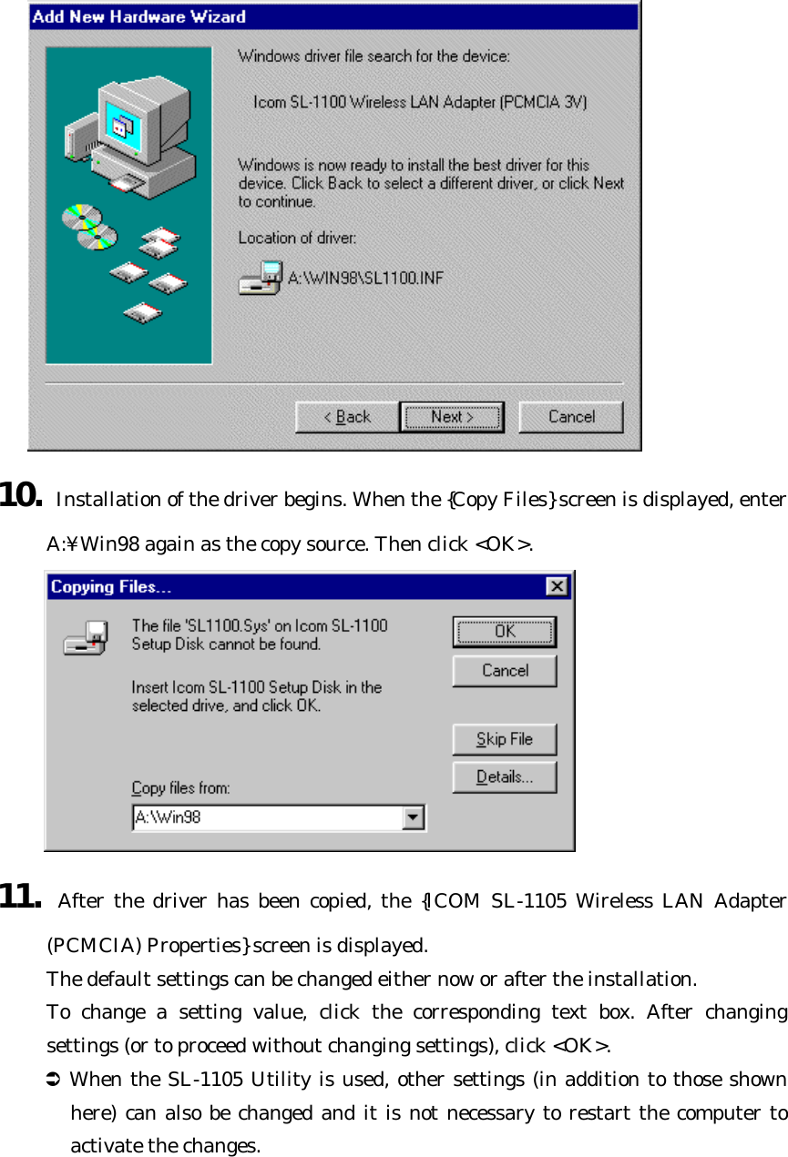
![8. Click <Next> to begin searching for the driver. If the driver cannot be located, click <Back>, select [Specify location], and enter "A:¥" as the directory where the driver is located. Then click <Next> to repeat the search. 9. When the driver has been located, the screen shown below will be displayed. Click <Next>.](https://usermanual.wiki/ICOM-orporated/SL-1105/User-Guide-129784-Page-14.png)
![3 Using in a Windows 98 Environment 3-3 Checking the LAN Card Driver and System Resources After installing the software, check for resource conflicts to make sure the SL-1105 is functioning properly on your computer. 1. Click <Start> and select [Control Panel] from the [Settings] menu. Double-click the [System] icon and select the [Device Manager] tab. 2. Double click [Network adapters]. If the LAN card driver is installed correctly, {ICOM SL-1105 Wireless LAN Adapter (PCMCIA)} will appear as shown below.](https://usermanual.wiki/ICOM-orporated/SL-1105/User-Guide-129784-Page-18.png)
![3. If {Icom SL-1105 Wireless LAN Adapter (PCMCIA)} is displayed as shown above, proceed to Step 4. Otherwise check the following: ÜIf {Icom SL-1105 Wireless LAN Adapter (PCMCIA)} is displayed under {Other devices} instead of {Network adapters}, uninstall the driver (Icom SL-1105 Wireless LAN Adapter (PCMCIA)) according to procedure described in {3-9 Uninstalling the LAN Card Driver.} Then reinstall the driver. Ü When software for a different wireless LAN card has already been installed, delete the driver for that LAN card and try installing only the driver for the SL-1105. 4. Double click {Icom SL-1105 Wireless LAN Adapter (PCMCIA).} in the screen as in Step 2. l Make sure "This device is working properly" appears under [Device status] on the [General] tab of the Properties screen.](https://usermanual.wiki/ICOM-orporated/SL-1105/User-Guide-129784-Page-19.png)
![5. Click <Start> and select [Control Panel] from the [Settings] menu. Then double-click the [PC Card (PCMCIA)] icon. l If {Icom SL-1105 Wireless LAN Adapter (PCMCIA)} appears on the [Socket Status] tab as shown below and the reception lamp on the SL-1105 is flashing, the card is functioning properly.](https://usermanual.wiki/ICOM-orporated/SL-1105/User-Guide-129784-Page-20.png)
![3 Using in a Windows 98 Environment 3-4 SL-1105 Settings After making sure the SL-1105 is functioning properly, adjust the communication and security settings of the SL-1105. 1. Click <Start> and select [Control Panel] from the [Settings] menu. Double-click the [Network] icon.](https://usermanual.wiki/ICOM-orporated/SL-1105/User-Guide-129784-Page-21.png)
![2. Double-click {Icom SL-1105 Wireless LAN Adapter (PCMCIA)}in the list of installed network components. Click the [Advanced] tab to display the screen shown below. l Windows98](https://usermanual.wiki/ICOM-orporated/SL-1105/User-Guide-129784-Page-22.png)
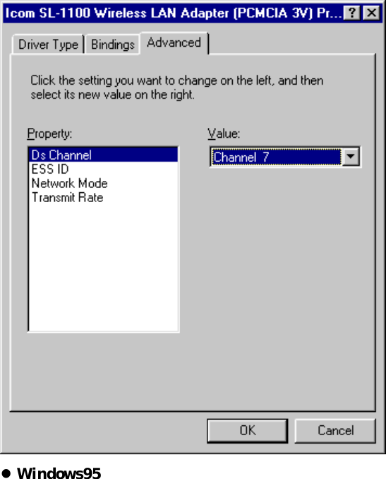
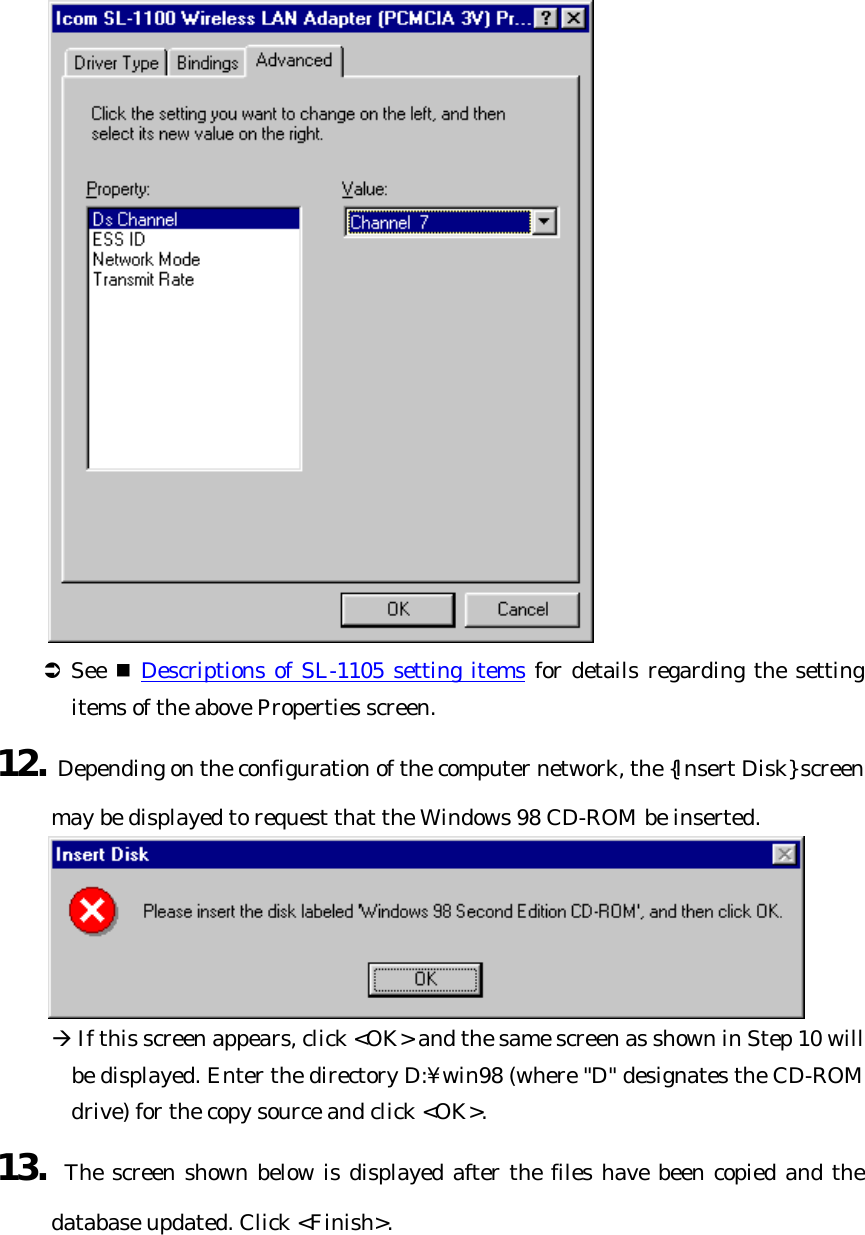
![3. To change a setting (property), click the name of the setting you wish to change. l Then select the new value from the text box under [Value]. n Descriptions of SL-1105 setting items The settings encountered in {3-4 SL-1105 Settings} are described. [Ds Channel]:default value = Channel 7 This setting item is the wireless transmission channel used for wireless network communications. It is valid when [Network Mode] is set to "Adhoc." Select the same channel as the other members of your wireless network group. The communication speed may decline when multiple wireless network groups (e.g., peer-to-peer) having different ESS IDs are configured within the same wireless transmission area. This problem can be avoided by having each wireless network group use a](https://usermanual.wiki/ICOM-orporated/SL-1105/User-Guide-129784-Page-24.png)
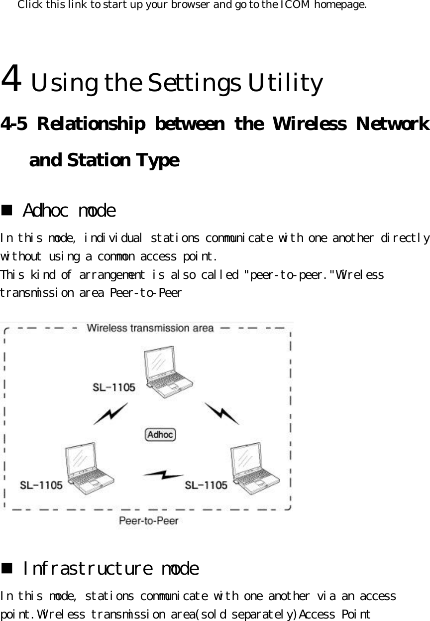
![different channel, thus eliminating interference between groups. However, since interference may continue to occur when closely neighboring channels are used, select channel settings that are at least four channels apart when using multiple wireless network groups. ÜWhen adjusting channels, be sure to select channels that will not interfere with the signals other wireless devices. ÜWhen [Network Mode] is set to "Infrastructure", Channels 1 to 14 are scanned sequentially. [ESS ID]:default value = LG This setting item serves as an arbitrary name for identifying a group within the wireless network. It is used when multiple wireless network groups (e.g., peer-to-peer) are configured within the wireless transmission area and there is network information that should not be viewed by other wireless network groups. Enter the same name as the other members of your wireless network group. ÜWhen entering the ESS ID, use up to 32 alphanumeric characters. Upper and lower case are distinguished. ÜThe ESS ID is distinguished from the "Workgroup Name" setting used on the wired network, but we recommend using the same name if possible. [Network Mode]:default value = Infrastructure This setting item establishes what kind of communication arrangement your computer will use to connect with the wireless network using the SL-1105. Refer to the figures below and select the appropriate connection method. lAdhoc : peer-to-peer connection lInfrastructure : connection via access point n Communication arrangements](https://usermanual.wiki/ICOM-orporated/SL-1105/User-Guide-129784-Page-25.png)
![Ü See "4-5 Relationship between the Wireless Network and Station Type" for details regarding the Network Mode. [Transmit Rate]:default value = Automatic This setting item is used to set the wireless transmission rate used when the LAN card transmits data. The transmission range is approximately 50 m indoors and 150 m in an open space. When the transmission rate is set to 11 Mbps, the transmission range is approximately 30 m indoors and 70 m in an open space.](https://usermanual.wiki/ICOM-orporated/SL-1105/User-Guide-129784-Page-26.png)
![ÜThe LAN card can receive wireless data transmissions at rates of 1 to 11 Mbps regardless of the value of this setting. [Rts/Cts Threshold]:default value = No Rts/Cts This setting item is used to establish whether or not RTS/CTS (request to send/clear to send) negotiations are conducted before data is exchanged with another computer. When negotiations are conducted, data transmission begins when the other party responds. For example, if this setting item is set to 500 bytes, then when the amount of data to be sent exceeds 500 bytes, the size of one packet of data sent for the purpose of negotiations is 500 bytes. ÜThis item is only displayed when Windows 95 is used. [Wep Decrypt]:default value = No This setting item establishes whether or not encrypted packets will be decrypted when they are received. ÜThis item is only displayed when Windows 95 is used. [Wep Default Key]:default value = 1 This setting item is used to select the key number (WepKey1 to WepKey4) used for encrypted transmission. ÜThis item is only displayed when Windows 95 is used. [Wep Encrypt]:default value = No This setting item is used to select whether or not packets to be sent will be encrypted. ÜThis item is only displayed when Windows 95 is used. [Wep Factor]:default value = 0 This setting item is used to establish the security level. "0" indicates the highest degree of security. {0} = updates internal encryption key for every packet. {1} = updates internal encryption key every five packets.](https://usermanual.wiki/ICOM-orporated/SL-1105/User-Guide-129784-Page-27.png)
![{2} = updates internal encryption key every ten packets. {3} = updates internal encryption key every fifty packets. ÜThis item is only displayed when Windows 95 is used. [Wep Mandatory]:default value = No This setting item is used to establish whether or not a received packet will be destroyed if it is not encrypted. ÜThis item is only displayed when Windows 95 is used. [Wep Mode]:default value = 64-bit encryption This setting item is used to select the number of encrypted bits. ÜThis item is only displayed when Windows 95 is used. [WepKey1-WepKey4]:default value =0000000000... For this setting item, enter a string of base-16 numerals (0 to F) with a length corresponding to the number of bits selected for [Wep Mode]. ÜThis item is only displayed when Windows 95 is used. 3 Using in a Windows 98 Environment 3-5 Connecting to a Wireless Network n Example of settings for peer-to-peer connection After completing the SL-1105 settings, it is necessary to specify information (i.e., computer name and workgroup name) that identifies your computer within the network. The procedure is explained briefly here, but see the explanation regarding networks in Windows 98 First Step Guide for details.](https://usermanual.wiki/ICOM-orporated/SL-1105/User-Guide-129784-Page-28.png)
![A.Checking and adding protocol If the LAN card driver has been installed correctly, the following protocols will have been installed in the computer: l"TCP/IP" l"Client for Microsoft Networks" [How to check the protocol] 1. Click <Start> and select [Control Panel] from the [Settings] menu. Then double-click the [Network] icon. The screen will appear as follows: 2. If the previously mentioned protocols are not in the list of installed network components, click [Add]. 3. The {Select Network Component Type} screen is displayed. To install a client for Microsoft Networks, double-click [Client]. To install TCP/IP protocol, double-click](https://usermanual.wiki/ICOM-orporated/SL-1105/User-Guide-129784-Page-29.png)
![[Protocol]. 4. One of the following two screens is displayed. For either case, select [Microsoft] as the manufacturer. l Client installation l Protocol installation](https://usermanual.wiki/ICOM-orporated/SL-1105/User-Guide-129784-Page-30.png)
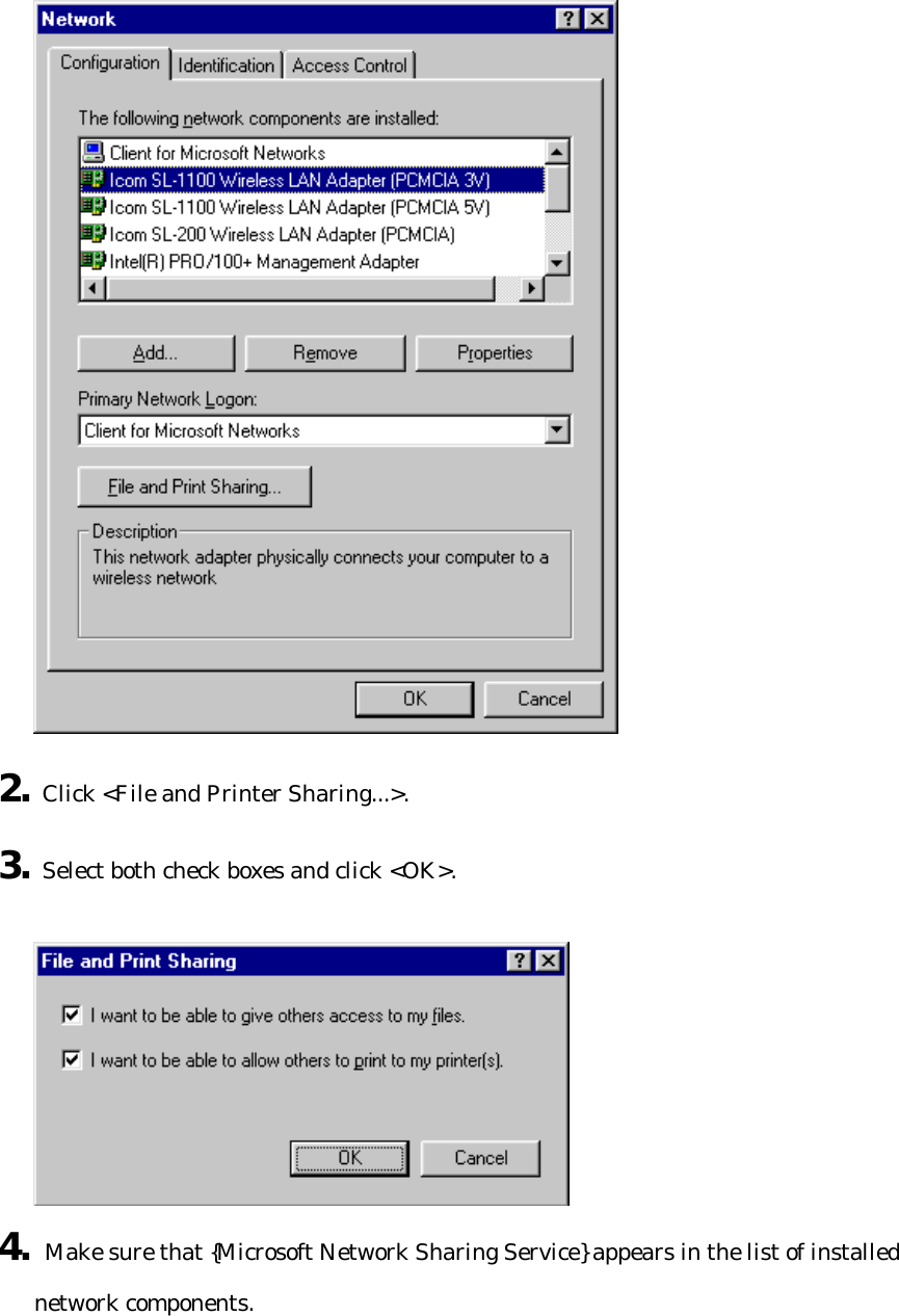
![5. When installing a client, select {Client for Microsoft Networks} under [Network Clients]. When installing a protocol, select {TCP/IP} under [Network Protocols]. 6. Click [OK]. 7. Click [OK] on the {Network} screen. 8. Restart your computer. B. Adding Microsoft Network Sharing Service 1. Click <Start> and select [Control Panel] from the [Settings] menu. Then double-click the [Network] icon. The screen will appear as follows:](https://usermanual.wiki/ICOM-orporated/SL-1105/User-Guide-129784-Page-31.png)
![C.TCP/IP settings 1. Click <Start> and select [Control Panel] from the [Settings] menu. Then double-click the [Network] icon. The screen will appear as follows: 2. Double-click {TCP/IP -> Icom SL-1105 Wireless LAN Adapter (PCMCIA)} in the list of installed network components. 3. The screen shown below is displayed. Select [Specify an IP address] and enter the appropriate numerals next to [IP Address] and [Subnet Mask].](https://usermanual.wiki/ICOM-orporated/SL-1105/User-Guide-129784-Page-33.png)
![4. Click <OK> and close the screen. [NOTE] he IP address comprises four values ranging from 1 to 255 separated by periods. The first part (network address) and the last part (broadcast address) of the IP address are handled as special addresses. Do not assign a value for these two parts of the IP address. Also, do not assign the same IP address as any other device in the network. The subnet mask comprises four values (0 and 255) separated by periods. Assign the same value for the subnet mask as is used by all other devices in the network. D. Identification settings 1. Click <Start> and select [Control Panel] from the [Settings] menu. Then](https://usermanual.wiki/ICOM-orporated/SL-1105/User-Guide-129784-Page-34.png)
![double-click the [Network] icon and select the [Identification] tab. The screen will appear as follows: 2. Enter the appropriate character string values into the text boxes under [Computer Name], [Workgroup], and [Computer Description]. The values can be any combination of 32 alphanumeric characters. [Computer name] This setting item is used to establish a name to identify each computer in the network. Do not use the same name as any other computer in the same network group. [Network group] All computers in the same network group must enter the same name for this setting item. Ü When a wireless network ESS ID is used, use the same name for the ESS ID of all](https://usermanual.wiki/ICOM-orporated/SL-1105/User-Guide-129784-Page-35.png)
![computers on the same network group. (See "3-4 SL-1105 Settings.") [Computer description] If necessary, enter a brief description of your computer. 3. Click <OK> and close the screen. 4. When the following message appears, click <YES> to restart the computer. Ü When the computer restarts, a dialog box requesting your network password will appear. Enter your user name and password. E. Sharing folders 1. Open the window, such as [My Computer] (whose icon is located on the desktop), containing the folder you wish to share. 2. Right click the folder. 3. Select [Share] from the shortcut menu.](https://usermanual.wiki/ICOM-orporated/SL-1105/User-Guide-129784-Page-36.png)
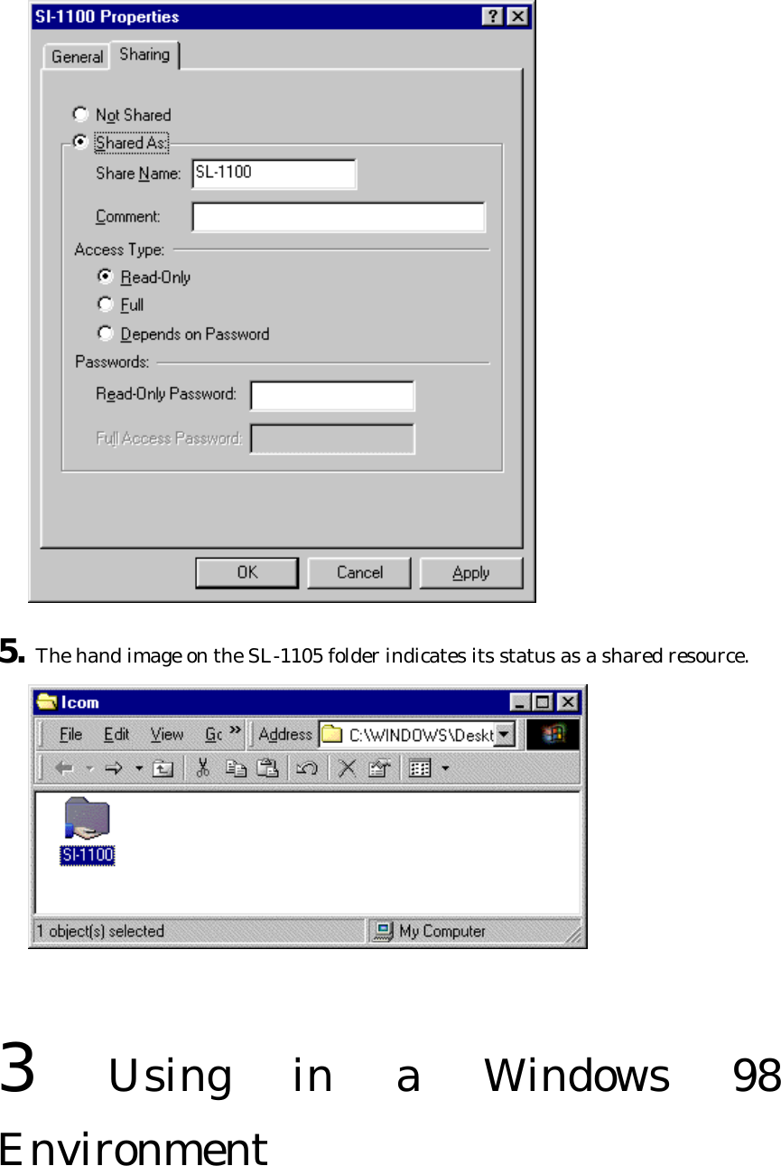
![4. Select [Share] and check or change the setting values for [Shared name], [Comments], [Access type], and [Password]. Then click <OK>.](https://usermanual.wiki/ICOM-orporated/SL-1105/User-Guide-129784-Page-37.png)
![3-6 Checking the Wireless Network Connection After completing the settings needed for connecting to the network, check if you can access the shared folders located in the other computers of your workgroup. Double-click the [Network Computer] icon and display the screen shown below. You have a good connection with the network if the screen includes each of the following: the [Entire Network] icon, an icon for your computer, and icons for the other members of your workgroup. Ü Use the [Entire Network] icon to view a list of other computers that are connected to network groups to which your computer does not belong (i.e., network groups with a different workgroup name). However, the list does not include computers belonging to network groups using different ESS IDs than the network group to which your computer belongs. Adjust the ESS ID appropriately for each network group when it is necessary to prevent some groups from viewing information regarding other groups. [NOTE] It takes a few moments for the icons of the other computers in your workgroup to appear when [Network] is selected. Similarly, it takes a few moments for the network list to appear when [Entire Network] is selected. If all of the icons do not appear, open the {Network} screen again. If the complete list still does not appear, try reviewing the information provided in the next section ("3-7 What to Do When the Other Computer(s) Cannot Be Recognized") or consult with the network manager.](https://usermanual.wiki/ICOM-orporated/SL-1105/User-Guide-129784-Page-39.png)
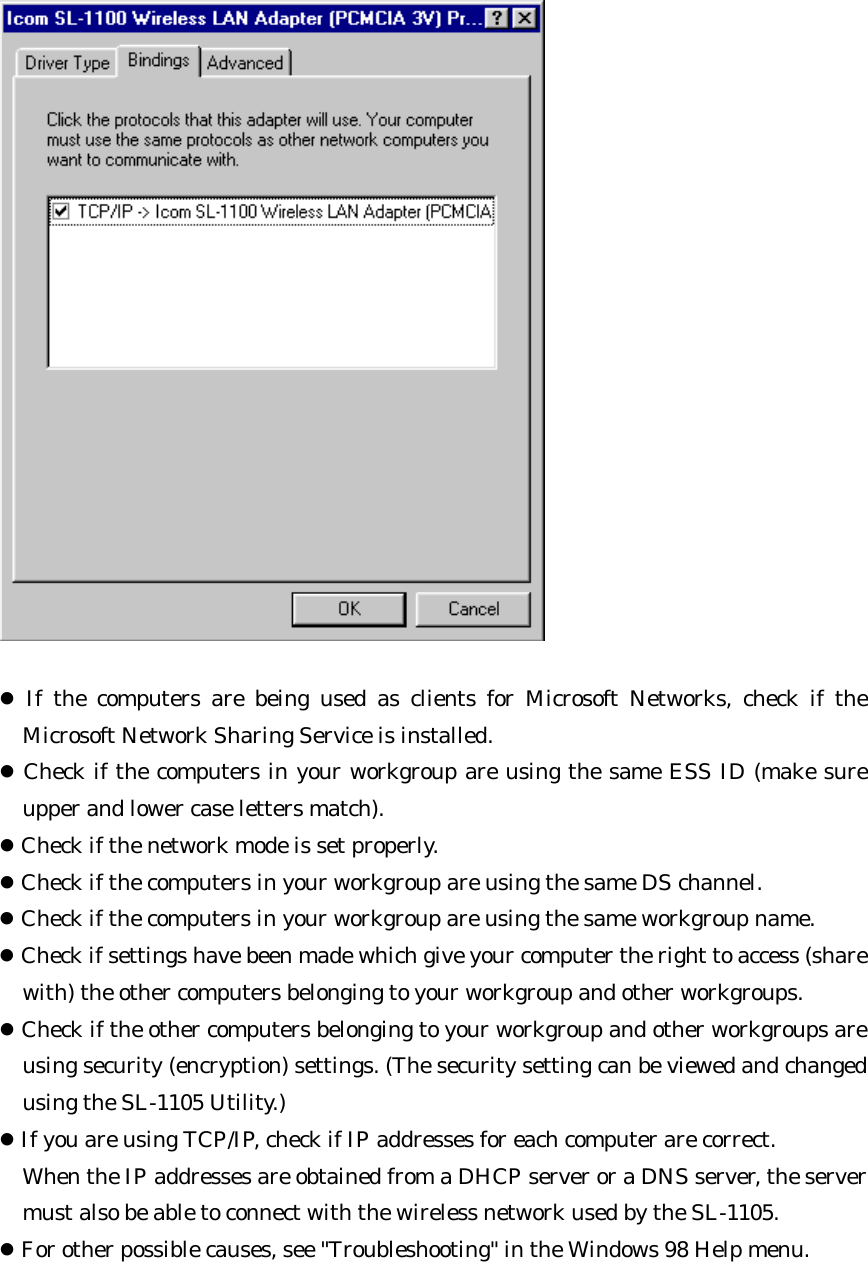
![3 Using in a Windows 98 Environment 3-7 What to Do When the Other Computer(s) Cannot Be Recognized Compare the settings with those of the other computers in the network as follows: l Check if the other computers in your network are using the same protocol. [How to check] Click <Start> and select [Control Panel] from the [Settings] menu. Double-click the [Network] icon. Then double-click [TCP/IP-> Icom SL-1100 Wireless LAN Adapter (PCMCIA)] in the list of installed components. Click the [Bindings] tab and make sure the check boxes for the protocols you are using are selected.](https://usermanual.wiki/ICOM-orporated/SL-1105/User-Guide-129784-Page-40.png)
![3 Using in a Windows 98 Environment 3-8 Removing the SL-1105 from the Card Slot Follow the procedure below to remove the SL-1105 correctly. Otherwise the system may run out of control. 1. Click <Start> and select [Control Panel] from the [Settings] menu. Then double-click the [PC Card (PCMCIA)] icon. 2. Click {Icom SL-1105 Wireless LAN Adapter (PCMCIA)} and then click <Stop>. 3. The message shown below is displayed after a few moments. Click <OK> and remove the SL-1105 from the card slot. Then click <OK> on the {PC Card (PCMCIA) Properties} screen.](https://usermanual.wiki/ICOM-orporated/SL-1105/User-Guide-129784-Page-42.png)
![[NOTE] If you select the check box next to "Show control on task bar" on the [PC Card (PCMCIA) Properties] screen, the [PC Card] icon will be displayed in the task tray on the bottom right of the desktop screen. You can arrive at the message shown in Step 3 above by clicking this icon and clicking the appropriate item from those displayed. 3 Using in a Windows 98 Environment 3-9 Uninstalling the LAN Card Driver n Deleting the driver using the My Computer icon Follow the procedure below to delete the LAN card driver from the Properties screen of My Computer (located on the desktop). 1. Click <Start> and select [Control Panel] from the [Settings] menu. Double-click the [System] icon and select the [Device Manager] tab. 2. Double-click {Network adapters} and select {Icom SL-1100 Wireless LAN Adapter (PCMCIA)}.](https://usermanual.wiki/ICOM-orporated/SL-1105/User-Guide-129784-Page-43.png)
![3. Click <Remove>. The message "Restart computer now?" is displayed. Click <Yes>. The computer restarts and the uninstallation is complete. n Deleting the driver using the Network icon Follow the procedure below to delete the LAN card driver from the Network screen of Control Panel. 1. Click <Start> and select [Control Panel] from the [Settings] menu. Double-click the](https://usermanual.wiki/ICOM-orporated/SL-1105/User-Guide-129784-Page-44.png)
![[Network] icon. 2. Double-click {Network Adapters} and select {Icom SL-1105 Wireless LAN Adapter (PCMCIA)}. 3. Click <Remove> and follow the instructions on the screen. When the message "Restart computer now?" is displayed, click <Yes>. The computer restarts and the uninstallation is complete.](https://usermanual.wiki/ICOM-orporated/SL-1105/User-Guide-129784-Page-45.png)
![3 Using in a Windows 98 Environment 3-10 Checking the Network Setting Values Follow the procedure below to check the IP address. The IP address can be checked or reacquired by executing "winipcfg.exe," which is located in the Windows folder. [How to start winipcfg.exe] 1. Click <Start> and select <Run>. 2. Type "winipcfg" in the command box and press the Enter key. l When winipcfg.exe starts up, the {IP Settings} screen will be displayed: 3. Click the [Down Arrow] on the right side of the text box and select "Icom SL-1105 Wireless LAN Adapter." The setting values are displayed. lAdapter address : MAC address of the computer lIP address : IP address of the computer lSubnet mask : Net mask associated with the IP address of the LAN side of the computer](https://usermanual.wiki/ICOM-orporated/SL-1105/User-Guide-129784-Page-46.png)
![4 Using the Settings Utility 4-1 About the ICOM SL-1105 Utility The ICOM SL-1105 Utility can be used to change the settings of the SL-1105 without restarting your computer and to monitor the settings and communication status of the computers operating in the wireless network group area. Ü Windows 95 does not support this utility. 4-2 Installing the ICOM SL-1105 Utility Install the driver using the LAN Card Utility Software disks. [IMPORTANT] Make backup copies of the {SL-1105 LAN Card Utility Software} disks and use the backup disks for the operations described in this manual. 1. Close all applications that are running on your computer. 2. Insert the backup disk containing the {SL-1105 LAN Card Utility Software} into the floppy disk drive (Drive A). 3. Click <Start> and select [Run]. 4. Enter {A:¥Utils¥Setup.exe} in the command box and press the Enter key. When the setup program starts up, the screen shown below will be displayed. Follow the instructions on the screen.](https://usermanual.wiki/ICOM-orporated/SL-1105/User-Guide-129784-Page-47.png)
![5. Click the check boxes to adjust the optional settings as desired. Then click [Finish]. Ü If you select [Run automatically after Windows starts up], the Utility will be registered in the Windows Startup folder and will start up simultaneously with the operating system.](https://usermanual.wiki/ICOM-orporated/SL-1105/User-Guide-129784-Page-48.png)
![4 Using the Settings Utility 4-3 Starting and Terminating the ICOM SL-1105 Utility 1. Make sure the SL-1105 is inserted in to the PCMCIA card slot. 2. Click <Start> and select [Icom SL-1105 Utility] from the [Program] menu. The Utility starts up and an icon indicating that the Utility is running is displayed on the task bar. n One of the following three icons is displayed to indicate the status of the card. à This icon indicates that the SL-1105 is inserted into the card slot and the [Network Mode] is set correctly. à This icon indicates that the computer cannot recognize the SL-1105. Possible causes include the driver being installed incorrectly. à This icon indicates either that the [Network Mode] is not set correctly for the wireless network being used or that the SL-1105 is outside the wireless transmission area. 3. Right-click the SL-1105 Utility icon on the task bar. Select "Display Monitor" from the menu that appears.](https://usermanual.wiki/ICOM-orporated/SL-1105/User-Guide-129784-Page-49.png)
![Ü When the {Icom SL-1105 Utility} is running in the computer, the icon mentioned above will be displayed on the task bar. The {Icom SL-1105 Utility} will start up even if the LAN card is not inserted, but the settings on the [Communication Settings] tab cannot be changed. 4. When communications are already in progress, the screen appears as follows: 5. Click <OK> to close the SL-1105 Utility screen. 6. To shut down the [Icom SL-1105 Utility], right-click the SL-1105 Utility icon on the task bar and select "Shut Down" from the menu that appears. l The SL-1105 Utility icon disappears and the utility shuts down.](https://usermanual.wiki/ICOM-orporated/SL-1105/User-Guide-129784-Page-50.png)
![n Button descriptions <OK> à Saves the setting changes and closes the screen <Cancel> à Closes the screen without changing the settings <Apply> à Saves the setting changes without closing the screen 4 Using the Settings Utility 4-4 Description of the ICOM SL-1105 Utility Screen Tabs n [Communication Status] tab [Station] tab](https://usermanual.wiki/ICOM-orporated/SL-1105/User-Guide-129784-Page-51.png)
![This area displays information (IP address, network mode, ESS ID, MAC address) regarding the SL-1105 installed in your computer. Ü When the IP address is unknown, the MAC address of the LAN card installed in the card slot is displayed. Signal quality (strength) This area displays the strength of the signal received from the coordinator. Ü When using peer-to-peer communications, the signal strength is alwasys indicated at the maximum level because the beacon signal emitted from your own station is received. Access point This area displays information (MAC address or IP address) regarding the access point that can be accessed by the SL-1105. Ü The status of the check box next to "Display IP address" determines whether the MAC address or the IP address is displayed. When the check is removed, the MAC address is displayed. Display IP address When the check is removed from the check box, both the station and access point addresses are indicated as a MAC address. When the IP address is unknown, the IP address cannot be displayed and the MAC address is displayed by default. Communication status This item indicates the current communication status. Transmission speed This item indicates the current transmission speed setting. DS channel This item indicates current DS (direct spread) channel setting. n [Communication Statistics] tab](https://usermanual.wiki/ICOM-orporated/SL-1105/User-Guide-129784-Page-52.png)
![<Stop Diagnostics> à This button stops displaying the graphs of the diagnostic results. <Start Diagnostics> à This button starts displaying the graphs of the diagnostic results. <Reset Statistics> à This button clears the graphs. Transmission speed à When this check box is selected, the data transmission speed is displayed as an amount of data per second. Reception speed à When this check box is selected, the data reception speed is displayed as an amount of data per second. Transmission error à When this check box is selected, the percentage of data transmitted incorrectly each second is displayed. Reception error à When this check box is selected, the percentage of data received incorrectly each second is displayed. n [Communication Settings] tab](https://usermanual.wiki/ICOM-orporated/SL-1105/User-Guide-129784-Page-53.png)
![Network settings This area is used to set the [Network Mode] and [ESS ID] of the SL-1105 inserted in the card slot of the computer. Ü See n Descriptions of SL-1105 setting items for details regarding the [Network Mode] and the [ESS ID]. Communication settings This area is used to adjust settings related to data transmission. [Rts/Cts Threshold] is used to establish whether or not RTS/CTS (request to send/clear to send) negotiations are conducted before data is exchanged with another computer. When negotiations are conducted, data transmission begins when the other party responds. For example, if this setting item is set to 500 bytes, then when the amount of data to be sent exceeds 500 bytes, the size of one packet of data sent for the purpose of negotiations is 500 bytes. Ü See n Descriptions of SL-1105 setting items for details regarding the [Transmission Speed] and [DS Channel]. Save as default settings hen this check box is selected, the setting changes will remain valid after the](https://usermanual.wiki/ICOM-orporated/SL-1105/User-Guide-129784-Page-54.png)
![computer has been restarted. When the check is removed from this check box, the changed settings will only be valid until the computer is turned off or restarted. After the computer is restarted, the previous setting values will be reinstated. n [Security] tab Security level This area is used to set the degree of encryption used to protect the data transmitted over the network. The SL-1105 uses the WEP (Wired Equivalent Privacy) encryption format. Optional Advanced settings related to the selected level (Low, Middle, High) can be accessed by selecting the [Show options] check box. Ü We recommend using the same security level as the other computers with which you are communicating. However, it is possible for a computer having a security level setting of {Low} to communicate with another computer having a security level setting of {Middle}. Key generator This area is used to set a character string for generating the key used for encryption](https://usermanual.wiki/ICOM-orporated/SL-1105/User-Guide-129784-Page-55.png)
![and decryption. Ü Use the same character string (arbitrary combination of alphanumeric characters and symbols for which upper and lower case letters are distinguished) as the other computers with which you are communicating. If different character strings are used, the encrypted data cannot be decrypted. ShowDisplay options When this check box is selected, the optional setting screen is displayed. The settings shown on the optional setting screen and the level selected from the [Security Level] area are linked. If the settings automatically determined in the optional setting screen after a certain security level had been selected match the settings made from the optional setting screen, then the check box for the corresponding security level will be selected automatically. Save as default settings When this check box is selected, the setting changes (including optional settings) will remain valid after the computer has been restarted. When the check is removed from this check box, the changed settings will only be valid until the computer is turned off or restarted. After the computer is restarted, the previous setting values will be reinstated. n [Security] tab (optional settings) this tab is used to perform advanced settings when {Custom} is selected under [Security Level].](https://usermanual.wiki/ICOM-orporated/SL-1105/User-Guide-129784-Page-56.png)
![WEP settings This area is used for settings related to the encryption and decryption of data transmitted to and received from the wireless network. WEP key When 64-bit encryption is selected, the keys generated from the character string entered into the [Key Generator] text box are displayed in text boxes 1, 2, 3, and 4 in 40-bit segments (base 16, 10 characters). When 128-bit encryption is selected, the keys are displayed in 104-bit segments (base 16, 26 characters). (The leading 24 bits are not displayed.) Only the selected key (1, 2, 3, or 4) is used for encryption. Decryption can only be accomplished when the other computer is using one of the keys shown here (1, 2, 3, or 4) for encryption. Ü The keys can also be entered directly into the WEP key text boxes (1, 2, 3, and 4). When this is done, a character string is not displayed in the [Key Generator] text box.Only the selected keys WEP factor This setting item is used to establish the security level. "0" indicates the highest degree of security. Each encryption level is defined as follows:](https://usermanual.wiki/ICOM-orporated/SL-1105/User-Guide-129784-Page-57.png)
![{0} = updates internal encryption key for every packet {1} = updates internal encryption key every five packets {2} = updates internal encryption key every ten packets {3} = updates internal encryption key every fifty packets 64-bit encryption Select this setting to conduct 64-bit encryption. The last 40 bits (base 16, 10 characters) are shown in the WEP key text boxes. 128-bit encryption Select this setting to conduct 128-bit encryption. The last 104 bits (base 16, 10 characters) are shown in the WEP key text boxes. n [About SL-1105 Utility] tab Product information This area provides information regarding the SL-1105 Utility software. Display banner Select this check box to display the "WAVEMASTER" image file when the Utility is started up. To ICOM homepage](https://usermanual.wiki/ICOM-orporated/SL-1105/User-Guide-129784-Page-58.png)
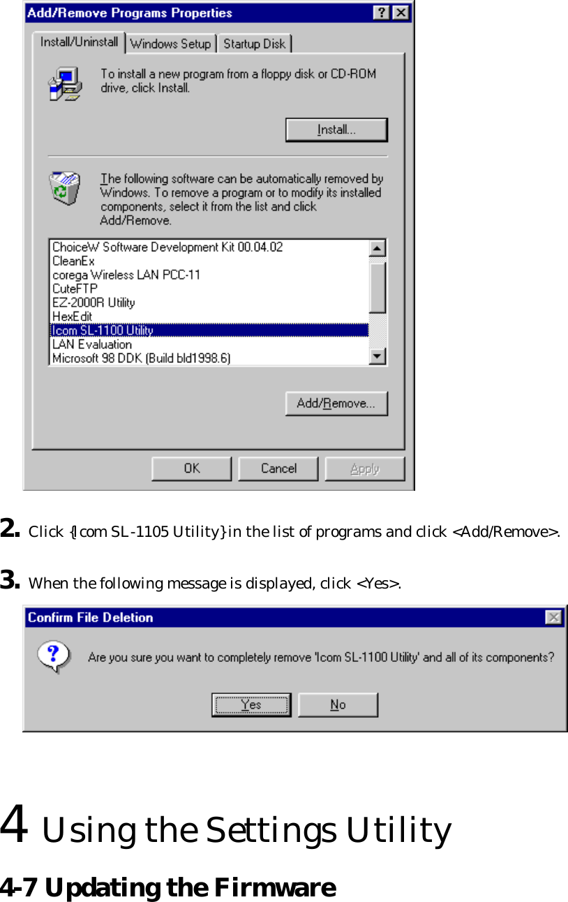
![4 Using the Settings Utility 4-6 Uninstalling the ICOM SL-1105 Utility 1. Click <Start> and select [Control Panel] from the [Settings] menu. Then double-click [Add/Remove Programs]. The {Add/Remove Programs} screen is displayed. Ü The following explanation is based on Windows 98. For other operating systems, follow the same procedure used to uninstall any other program.](https://usermanual.wiki/ICOM-orporated/SL-1105/User-Guide-129784-Page-60.png)
![n About firmware "Firmware" refers to programs written into the flash memory of the SL-1105 at the factory. These programs help the SL-1105 operate. l New versions of these programs are sometimes created to expand or improve the functions of the product. By updating these programs, you can add functions and keep your LAN card operating at its peak potential. l You can check the version of your firmware using [About SL-1105 Utility] tab of the SL-1105 Utility screen. n About the latest version Our homepage provides information about firmware updates. l Check our homepage regularly at [http://www.icomamerica.com/] l See the file attached to the downloaded data for instructions on how to update your firmware. Before downloading, read the license agreement for using our homepage.](https://usermanual.wiki/ICOM-orporated/SL-1105/User-Guide-129784-Page-62.png)
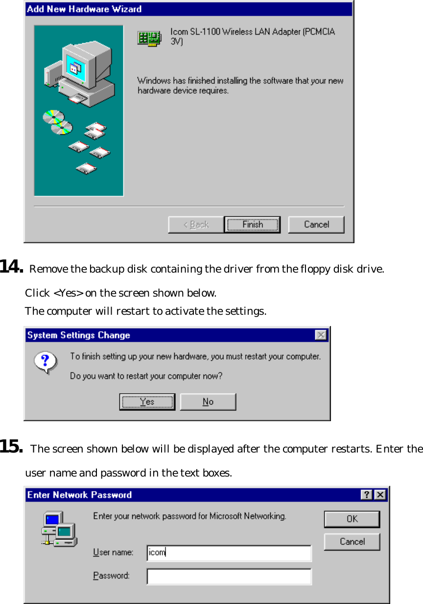
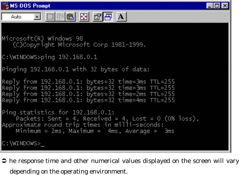
](https://usermanual.wiki/ICOM-orporated/SL-1105/User-Guide-129784-Page-63.png)
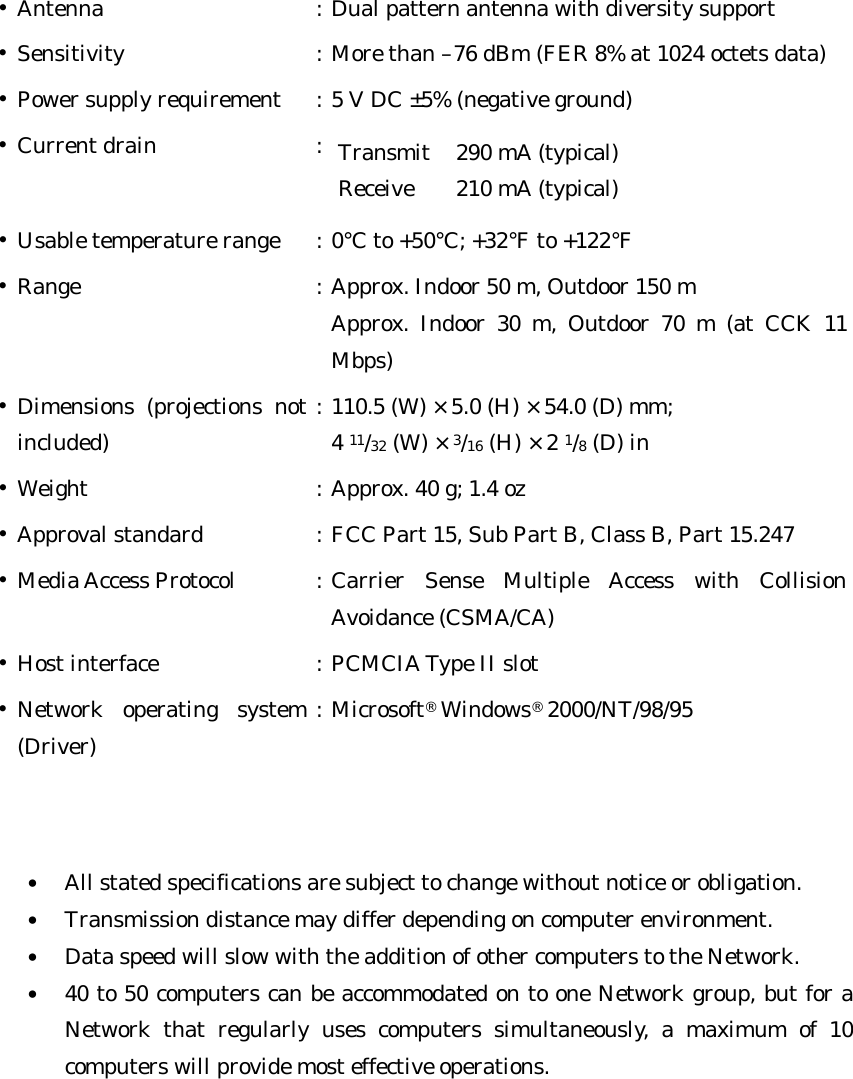
![6 Maintenance and Specifications n Servicing l Warranty At the time of purchase, the retailer will provide a warranty sheet complete with the details of the purchase (date of purchase, name of store). Make sure the information is correct and keep the warranty in a safe place for future use. l Requesting servicing Refer to the instruction manual and check the settings of the computer and the LAN card. If you cannot solve the problem, request servicing according to the following terms: [During the warranty period] Contact the store where you purchased the product. The retailer will service the product in accordance with the warranty. Have your warranty ready at the time of request. [After the warranty period] Contact the store where you purchased the product. If the product is serviceable, the retailer will repair the product for a fee. n SPECIFICATION Ÿ Wireless Medium : Direct Sequence Spread Spectrum (DSSS) Ÿ Network Standard : Based on IEEE 802.11b Ÿ Frequency Band : 2400 – 2483.5 MHz Ÿ Number of channels : 11 Ÿ Modulation : DBPSK DQPSK CCK at 1 Mbps at 2 Mbps at 5.5 and 11 Mbps Ÿ Encryption : 64-bit or 128-bit WEP Ÿ Output Power : 20 mW Ÿ Frequency stability : ±20 ppm (0°C to +50°C; +32°F to +122°F)](https://usermanual.wiki/ICOM-orporated/SL-1105/User-Guide-129784-Page-65.png)