ICP C9MPV075F12B1 User Manual 90+ 2 STAGE & VARIABLE SPEED BLOWER GAS FURNACE Manuals And Guides L0504464
ICP Furnace/Heater, Gas Manual L0504464 ICP Furnace/Heater, Gas Owner's Manual, ICP Furnace/Heater, Gas installation guides
User Manual: ICP C9MPV075F12B1 C9MPV075F12B1 ICP 90+ 2-STAGE & VARIABLE-SPEED BLOWER GAS FURNACE - Manuals and Guides View the owners manual for your ICP 90+ 2-STAGE & VARIABLE-SPEED BLOWER GAS FURNACE #C9MPV075F12B1. Home:Heating & Cooling Parts:Icp Parts:Icp 90+ 2-STAGE & VARIABLE-SPEED BLOWER GAS FURNACE Manual
Open the PDF directly: View PDF ![]() .
.
Page Count: 60
90+2-Stage &*9MPT & *9MPV
Variable Speed
SAFETY REQUIREMENTS
/X
Recognize safety information. This is the safety-alert symbolL±_. _ . When you see this symbol on the furnace and in instructions or manuals be alert
to the potential for personal injury.
Understand the signal words DANGER, WARNING, or CAUTION. These words are used with the safety-alert symbol. DANGER identifies the
most serious hazards, those that will result in severe personal injury or death. WARNINGsignifiesahazardthatcouldresultinpersonalinjuryor
death. CAuT__N is used t_ identify unsafe practices that c_u_d resu_t in min_r pers_na_ injury _r _r_duct and pr__erty damage.
Installing and servicing heating equipment can be hazardous due to gas and electrical components. Only trained and qualified personnel should
install, repair, or service heating equipment.
Untrained service personnel can perform basic maintenance functions such as cleaning and replacing air filters. All other operations must be
performed by trained service personnel. When working on heating equipment, observe precautions in the literature, on tags, and on labels attached
to or shipped with the unit and other safety precautions that may apply.
Follow all safety codes. In the United States, follow all safety codes including the current edition National Fuel Gas Code (NFGC) NFPA No.
54/ANSIZ223.1. InCanada, refer tothecurrent editionofthe NationalStandard Canada CAN/CGA-B149.1- and.2-M91 NaturalGasand Propane
InstallationCodes (NSCNGPIC). Wearsafetyglassesandworkgloves. Havefireextinguisher availableduringstart-upandadjustment procedures
and service calls.
These instructions cover minimum requirements and conform to existing national sta nda rds and safety codes. In some insta rices, these instructions
exceed certain local codes and ordinances, especially those that may not have kept up with changing residential construction practices. We requre
these instructions as a minimum for a safe installation.
Manufactured by:
International Comfort Products Corporation (USA)
Lewisburg, TN 37091
Table of Contents
1. Safe Installation Requirements ................. 4
2. Installation ................................ 5
3. Combustion & Ventilation Air .................. 8
4. Vent &Combustion Air Piping ................ 10
5. Gas Supply and Piping ...................... 21
6. Electrical Wiring ........................... 25
7. DuctworkandFilter ........................ 26
8. ChecksandAdjustments.................... 30
9. FurnaceMaintenance ....................... 32
10.Sequenceof Operation&Diagnostics.......... 32
11.ConcentricVentTermination................. 38
12.TechSupportandParts .................... 41
FIRE OR EXPLOSION HAZARD
This furnace is not designed for use in mobile
homes, trailers or recreational vehicles.
Such use could result in death, bodily injury
and/or property damage.
PrintedinU.S.A. LP1 12/2/2002 440 01 2113 (02)
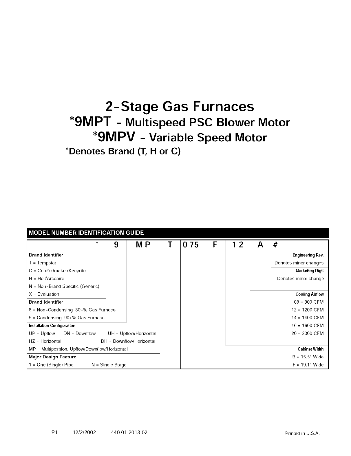
2-Stage Gas Furnaces
*9MPT - Multispeed PSC Blower Motor
*9MPV -Variable Speed Motor
*Denotes Brand (T, H or C)
9 MP
Brand Identifier
=Tempstar
C=Comfortmaker/Keeprite
H=Heil/Arcoaire
N=Non-Brand Specific (Generic)
× = Evaluation
Brand Identifier
8=Non-Condensing, 80+% Gas Furnace
9=Condensing, 90+% Gas Furnace
InstallationConfiguration
UP =Upflow DN =Downflow UH =Upflow/Horizontal
HZ = Horizontal DH = Downflow/Horizontal
MP = Multiposition, Upflow/Downflow/Horizontal
Major Design Feature
1 = One (Single) Pipe N = Single Stage
T075 F 12 A #
EngineeringRev.
Denotes minor changes
MarketingDigit
Denotes minor change
Cooling Airflow
08 =800 CFM
12 =1200 CFM
14 =1400 CFM
16 = 1600 CFM
20 = 2000 CFM
Cabinet Width
B=15.5" Wide
F=19.1" Wide
LP1 12/2/2002 440 01 2013 02 Printed in U.S.A.
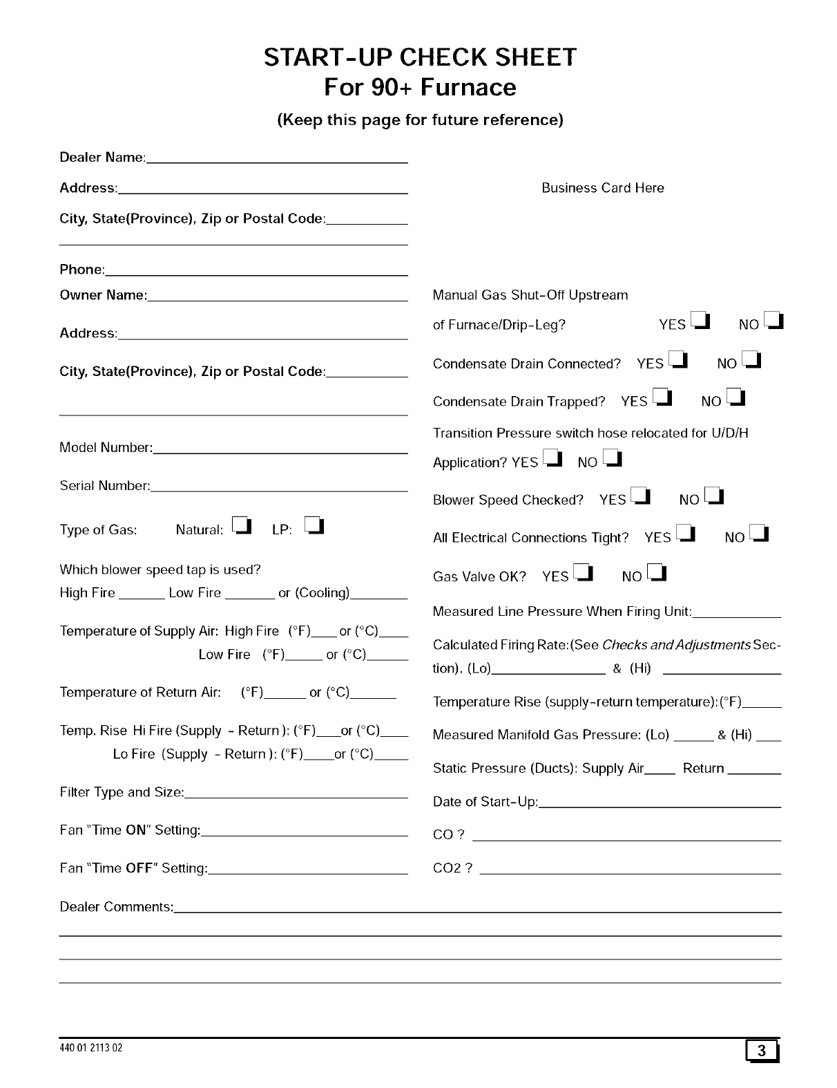
START-UP CHECK SHEET
For 90+ Furnace
(Keep this page for future reference)
Dealer Name:
Address:
City, State(Province), Zip or Postal Code:
Business Card Here
Phone:
Owner Name:
Address:
City, State(Province), Zip or Postal Code:
Model Number:
Serial Number:
Type of Gas: Natural: _ LP:
Which blower speed tap is used?
High Fire __ Low Fire or (Cooling)
Temperature of Supply Air: High Fire (°F)__ or (°C)__
Low Fire (°F).__or (°C)__
Temperature of Return Air: (°F)__ or (°C)__
Temp. Rise Hi Fire (Supply - Return ): (°F) or (°C)__
Lo Fire (Supply - Return ): (°F) or (°C).__
Filter Type and Size:
Fan "Time ON" Setting:
Fan "Time OFF" Setting:
Manual Gas Shut-Off Upstream
of Furnace/Drip- Leg?
Condensate Drain Connected?
YES
YES
Condensate Drain Trapped? YES
NOE_
NO
NO
Transition Pressure switch hose relocated for U/D/H
Application? YES _ NO
Blower Speed Checked? YES _ NO
All Electrical Connections Tight? YES _ NO
Gas Valve OK? YES _ NO
Measured Line Pressure When Firing Unit:
Calculated Firing Rate: (See Checks andAdjustments Sec-
tion). (Lo) & (Hi)
Temperature Rise (supply-return temperature):(°F)__
Measured Manifold Gas Pressure: (Lo) __ & (Hi) __
Static Pressure (Ducts): Supply Air Return
Date of Start-Up:
CO?
CO2 ?
Dealer Comments:
44001211302
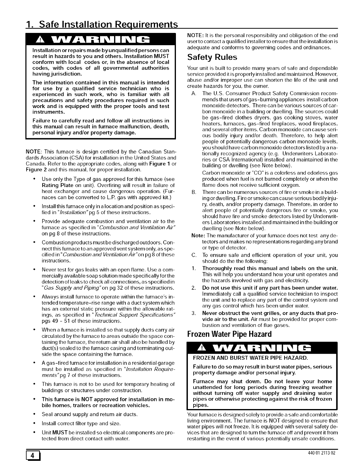
1. Safe Installation Requirements
Installation or repairs made by unqualified persons can
result in hazards to you and others. Installation MUST
conform with local codes or, in the absence of local
codes, with codes of all governmental authorities
havingjurisdiction.
The information contained in this manual is intended
for use by a qualified service technician who is
experienced in such work, who is familiar with all
precautions and safety procedures required in such
work and is equipped with the proper tools and test
instruments.
Failure to carefully read and follow all instructions in
this manual can result in furnace malfunction, death,
personal injury and/or property damage.
NOTE: This furnace is design certified by the Canadian Stan-
dards Association (CSA) for installation in the United States and
Canada. Refer to the appropriate codes, along with Figure 1 or
Figure 2 and this manual, for proper installation.
•Use only the Type of gas approved for this furnace (see
Rating Plate on unit). Overfiring will result in failure of
heat exchanger and cause dangerous operation. (Fur-
naces can be converted to L.R gas with approved kit.)
• Install this furnace only in a location and position as speci-
fied in "lnstallation"pg 5 of these instructions.
• Provide adequate combustion and ventilation air to the
furnace as specified in "Combustion and Ventilation Air"
on pg 8 of these instructions.
• Combustion products must be discharged outdoors. Con-
nect this furnace to an approved vent system only, as spe-
cified in "Combustion and Ventilation Air"on pg 8 of these
instructions.
• Never test for gas leaks with an open flame. Use a com-
mercially available soap solution made specifically for the
detection of leaks to check all connections, as specified in
"Gas Supply and Piping"on pg 32 of these instructions.
• Always install furnace to operate within the furnace's in-
tended temperature-rise range with a duct system which
has an external static pressure within the allowable rat-
ings, as specified in "Technical Support Specifications"
pgs 49 - 51 of these instructions.
• When a furnace is installed so that supply ducts carry air
circulated by the furnace to areas outside the space con-
taining the furnace, the return air shall also be handled by
duct(s) sealed to the furnace casing and terminating out-
side the space containing the furnace.
• A gas-fired furnace for installation in a residential garage
must be installed as specified in "Installation Require-
ments"pg 7 of these instructions.
• This furnace is not to be used for temporary heating of
buildings or structures under construction.
• This furnace is NOT approved for installation in mo-
bile homes, trailers or recreation vehicles.
• Seal around supply and return air ducts.
• Install correct filter type and size.
• Unit MUST be installed so electrical components are pro-
tected from direct contact with water.
NOTE: It is the personal responsibility and obligation of the end
user to contact a qualified installer to ensure that the installation is
adequate and conforms to governing codes and ordinances.
Safety Rules
Your unit is built to provide many years of safe and dependable
service provided it is properly installed and maintained. However,
abuse and/or improper use can shorten the life of the unit and
create hazards for you, the owner.
A. The U.S. Consumer Product Safety Commission recom-
mends that users of gas-burning appliances install carbon
monoxide detectors. There can be various sources of car-
bon monoxide in a building or dwelling. The sources could
be gas-fired clothes dryers, gas cooking stoves, water
heaters, furnaces, gas-fired fireplaces, wood fireplaces,
and several other items. Carbon monoxide can cause seri-
ous bodily injury and/or death. Therefore, to help alert
people of potentially dangerous carbon monoxide levels,
you should have carbon monoxide detectors listed by a na-
tionally recognized agency (e.g. Underwriters Laborato-
ries or CSA International) installed and maintained in the
building or dwelling (see Note below).
Carbon monoxide or "CO" is a colorless and odorless gas
produced when fuel is not burned completely or when the
flame does not receive sufficient oxygen.
B. There can be numerous sources of fire or smoke in a build-
ing or dwelling. Fire or smoke can ca use serious bodily inju-
ry, death, and/or property damage. Therefore, in order to
alert people of potentially dangerous fire or smoke, you
should have fire and smoke detectors listed by Underwrit-
ers Laboratories installed and maintained in the building or
dwelling (see Note below).
Note: The manufacturer of your furnace does not test any de-
tectors and makes no representations regarding any brand
or type of detector.
C. To ensure safe and efficient operation of your unit, you
should do the the following:
1. Thoroughly read this manual and labels on the unit.
This will help you understand how your unit operates and
the hazards involved with gas and electricity.
2. Do not use this unit if any part has been under water.
Immediately call a qualified service technician to inspect
the unit and to replace any part of the control system and
any gas control which has been under water.
3. Never obstruct the vent grilles, or any ducts that pro-
vide air to the unit. Air must be provided for proper com-
bustion and ventilation of flue gases.
Frozen Water Pipe Hazard
FROZEN AND BURST WATER PIPE HAZARD.
Failure to do so may result in burst water pipes, serious
property damage and/or personal injury.
Furnace may shut down. Do not leave your home
unattended for long periods during freezing weather
without turning off water supply and draining water
pipes or otherwise protecting against the risk of frozen
pipes.
Your furnace is designed solely to provide a safe and comfortable
living environment. The furnace is NOT designed to ensure that
water pipes will not freeze. It is equipped with several safety de-
vices that are designed to turn the furnace off and prevent it from
restarting in the event of various potentially unsafe conditions.
[_ 440 01 211302
Ifyourfurnaceremainsoffforanextendedtime, the pipes in your
home could freeze and burst, resulting in serious water damage.
Water may create a condition in which mold can grow in your
home. Certain types of mold have been reported to cause respi-
ratory problems or other serious health risks. Remedial actions,
including immediately drying all wet items, should be taken quick-
ly to help prevent the development of mold in your home.
If the structure will be unattended during cold weather you should
take these precautions.
Turn off the water supply to the structure and drain the wa-
ter lines if possible and add an antifreeze for potable water
to drain traps and toilet tanks. Open faucets in appropriate
areas.
-or-
Have someone check the structure frequently during cold
weather to make sure it is warm enough to prevent pipes
from freezing. Instruct them on a service agency to call to
provide service, if required.
-or-
3. Install a reliable remote sensing device that will notify
somebody of freezing conditions within the home.
Winter Shutdown
If you go away during the winter months and do not leave the heat
on in your home, the plastic transition box and the condensate
trap on the furnace must be protected from freeze damage.(See
Figure 8 trough Figure 12)
1. Disconnect the 5/8" OD rubber hose from the vent drain fit-
ting that is located downstream of the combustion blower.
Insert a funnel into the hose and pour four(4) ounces of
sanitary type (RV) antifreeze into the condensate trap. Re-
connect the 5/8" OD rubber hose to the stub on the vent
drain fitting. Secure with the hose clamp.
2. Disconnect the 3/4" OD rubber hose from the condensate
trap. Insert a funnel into the hose and and pour four(4)
ounces of sanitary type (RV) antifreeze into the plastic
Transition box. Squeeze the hose together near the end
and quickly reconnect the 3/4" OD rubber hose to the stub
on the condensate trap. Secure with the hose clamp.
When you return home, your furnace will be ready to start, as it is
not necessary to drain the antifreeze from the furnace.
2. Installation
CARBON MONOXIDE POISONING HAZARD.
Failure to properly vent this furnace or other appliances
can result in death, personal injury and/or property
damage.
This furnace can NOT be common vented or connected
to any type B, BW or L vent or vent connector, nor to any
portion of a factory-built or masonry chimney. If this
furnace is replacing a previously common-vented
furnace, it may be necessary to resize the existing vent
CAUTION
Special precautions MUST be made if installing furnace in an
area which may drop below freezing. This can cause
improper operation or damage to equipment. If furnace
environment has the potential of freezing, the drain trap and
drainline must be protected. The use of electric heat tape or
RV antifreeze is recommended for these installations. (See
"Condensate Trap Freeze Protection Section")
Do NOT operate furnace in a corrosive atmosphere
containing chlorine, fluorine or any other damaging
chemicals. Refer to Combustion & Ventilation Air section,
Contaminated Combustion Air.
and chimney to prevent oversizing problems for the
other remaining appliance(s). See Venting and Combus-
tion Air Check in Gas Vent Installation section. This
furnace MUST be vented to the outside.
Location and Clearances
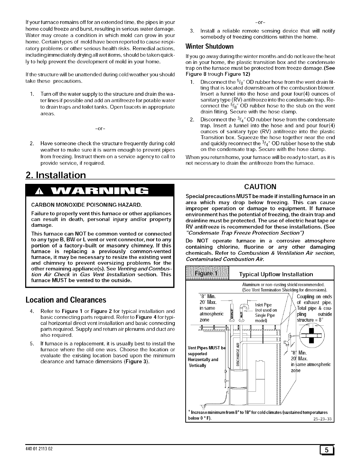
Refer to Figure 1 or Figure 2 for typical installation and
basic connecting parts required. Refer to Figure 4 for typi-
cal horizontal direct vent installation and basic connecting
parts required. Supply and return air plenums and duct are
also required.
5. If furnace is a replacement, it is usually best to install the
Typical Upflow Installation
Aluminumor non-rustingshieldrecommended.
(SeeVentTerminationShieldingfordimensions).
"8" Min.
20' Max. _ I_
_InletPipe
in same _-_ (notusedon
atmospheric _ Single Pipe
zone _> model)
furnace where the old one was. Choose the location or
evaluate the existing location based upon the minimum
clearance and furnace dimensions (Figure 3).
Vent Pipes MUST
supported
Horizontally and
Vertically
Coupling on ends
of exhaust pipe.
T0tal pipe & cou-
pling outside
i _ame atmospheric
?
*increaseminimumfrom8"to 18" for cold climates(sustainedtemperatures
below 0 oF), 25-23-33
44001 211302
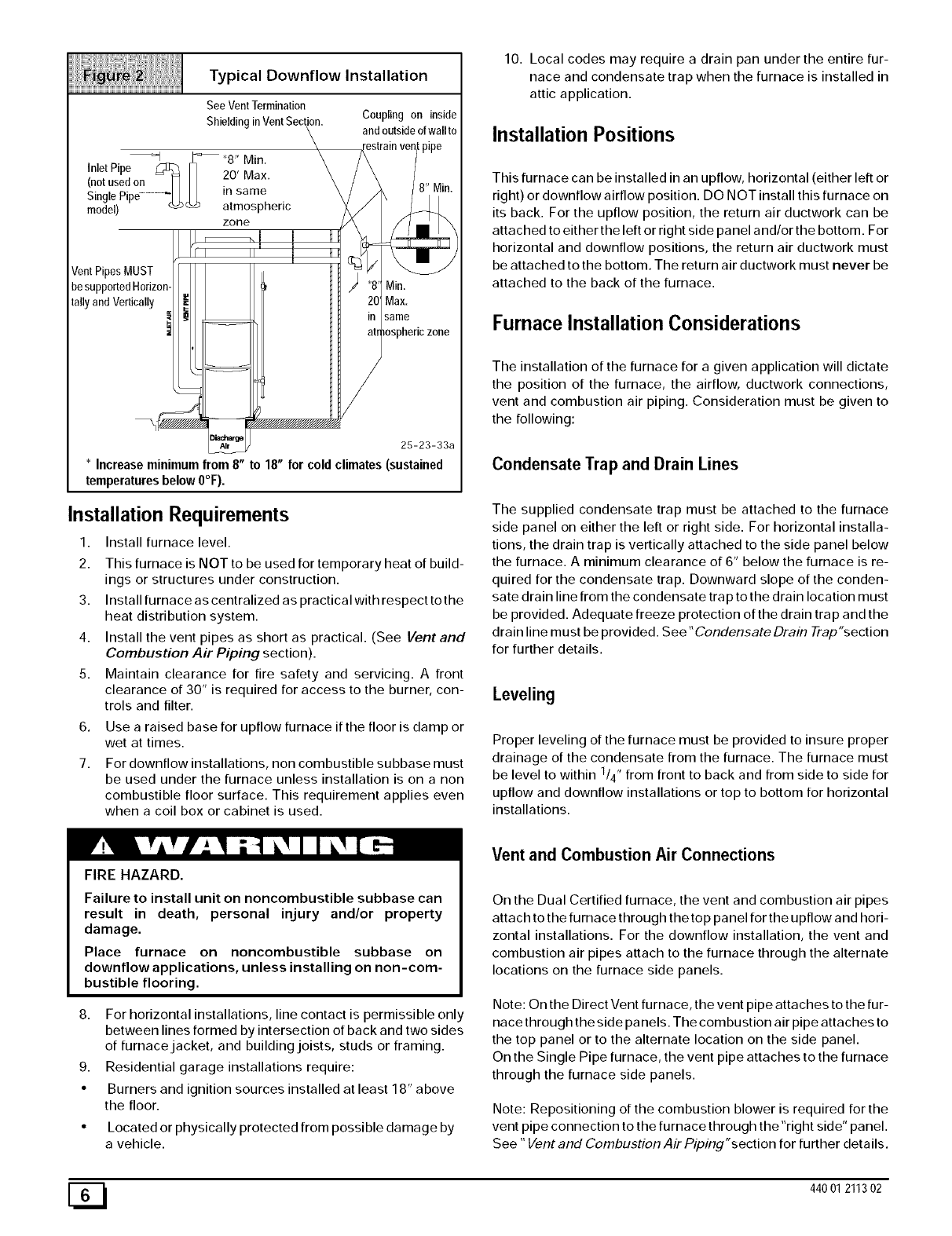
Typical Downflow Installation
See VentTermination
Shieldingin VentSection. Coupling on inside
and outsideof wall to
I_ "8" Min
Inlet Pipe C_ Iq .... "
(notusedon- I1 H fu ,v,a×.
Single Pipe........... _ in same
model) _ atmospheric
zone
Vent Pip MUST
be supp_ _dHorizor
tally and Vertically
/
Min.
Max.
same
zone
E_///////////////////////////_
25-23-33a
* Increase minimum from 8" to 18" for cold climates (sustained
temperatures below 0°F).
Installation Requirements
1. Install furnace level.
2. This furnace is NOT to be used for temporary heat of build-
ings or structures under construction.
3. Install furnace as centralized as practical with respect to the
heat distribution system.
4. Install the vent pipes as short as practical. (See Vent and
Combustion Air Piping section).
5. Maintain clearance for fire safety and servicing. A front
clearance of 30" is required for access to the burner, con-
trols and filter.
6.
7.
Use a raised base for upflow furnace if the floor is damp or
wet at times.
For downflow installations, non combustible subbase must
be used under the furnace unless installation is on a non
combustible floor surface. This requirement applies even
when a coil box or cabinet is used.
FIRE HAZARD.
10. Local codes may require a drain pan under the entire fur-
nace and condensate trap when the furnace is installed in
attic application.
Installation Positions
This furnace can be installed in an upflow, horizontal (either left or
right) or downflow airflow position. DO NOT install this furnace on
its back. For the upflow position, the return air ductwork can be
attached to either the left or right side panel and/or the bottom. For
horizontal and downflow positions, the return air ductwork must
be attached to the bottom. The return air ductwork must never be
attached to the back of the furnace.
Furnace Installation Considerations
The installation of the furnace for a given application will dictate
the position of the furnace, the airflow, ductwork connections,
vent and combustion air piping. Consideration must be given to
the following:
Condensate Trap and Drain Lines
The supplied condensate trap must be attached to the furnace
side panel on either the left or right side. For horizontal installa-
tions, the drain trap is vertically attached to the side panel below
the furnace. A minimum clearance of 6" below the furnace is re-
quired for the condensate trap. Downward slope of the conden-
sate drain line from the condensate trap to the drain location must
be provided. Adequate freeze protection of the drain trap and the
drain line must be provided. See "Condensate Drain Trap"section
for further details.
Leveling
Proper leveling of the furnace must be provided to insure proper
drainage of the condensate from the furnace. The furnace must
be level to within 1/4" from front to back and from side to side for
upflow and downflow installations or top to bottom for horizontal
installations.
Vent and Combustion Air Connections
Failure to install unit on noncombustible subbase can
result in death, personal injury and/or property
damage.
Place furnace on noncombustible subbase on
downflow applications, unless installing on non-com-
bustible flooring.
8. For horizontal installations, line contact is permissible only
between lines formed by intersection of back and two sides
of furnace jacket, and building joists, studs or framing.
9. Residential garage installations require:
• Burners and ignition sources installed at least 18" above
the floor.
Located or physically protected from possible damage by
a vehicle.
On the Dual Certified furnace, the vent and combustion air pipes
attach to the furnace through the top panel for the upflow and hori-
zontal installations. For the downflow installation, the vent and
combustion air pipes attach to the furnace through the alternate
locations on the furnace side panels.
Note: On the Direct Vent furnace, the vent pipe attaches to the fur-
nace through the side panels. The combustion air pipe attaches to
the top panel or to the alternate location on the side panel.
On the Single Pipe furnace, the vent pipe attaches to the furnace
through the furnace side panels.
Note: Repositioning of the combustion blower is required for the
vent pipe connection to the furnace through the "right side" panel.
See "Vent and Combustion Air Piping"section for further details.
[_ 440 01 211302
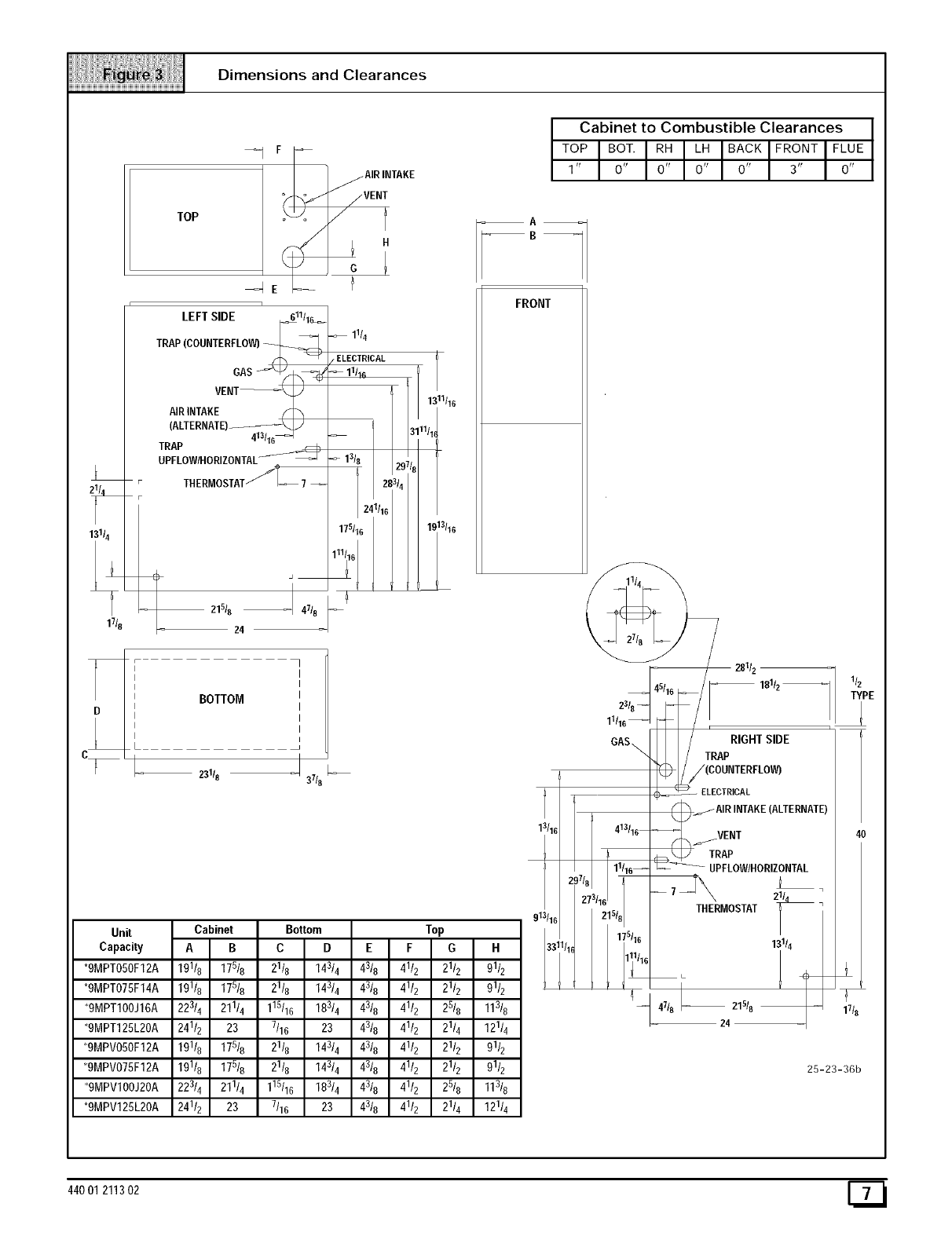
Dimensions and Clearances
11/8
TOP
1
LEFT SIDE _11/1_
T° ,OOO.T ° LO
VEN
_ __ ]_A,R,._KE
11/4
ELECTRICAL
11/16
AIRINTAKE S
(ALTERNATE) \
413/16_
TRAP
UPFLOW/HORIZONTAL_;_
THERMOSTATf_-_ 7--
I47t8
21518
24
_9
'4
1_11t16
/1_
1.c 13t16
BOTTOM
23118 37/8
Unit
Capacity
*9MPT050F12A
*9MPT075F14A
*9MPT100J16A
*9MPT125L20A
*9MPV050F12A
*9MPV075F12A
*9MPV100J20A
*9MPV125L20A
13/16
913116
33"
Cabinet to Combustible Clearances
TOPOOT.R_L_OA_KFRO.TFL_
1' O' O' O' O' 3' O'
FRONT
__= 281/z --
181/z
11116_ _
GAS_ _ TRApRIGHT SIDE
_._ /(COUNTERFLOW)
413/16
111/16_
17/827=/16215t8
175116
( _ ELECTRICAL
AIRINTAKE(ALTERNATE)
____VENT
TRAP
UPFLOWIHORIZONTAL
MOSTAT
13114
7
17t8
25-23-36b
44001 211302
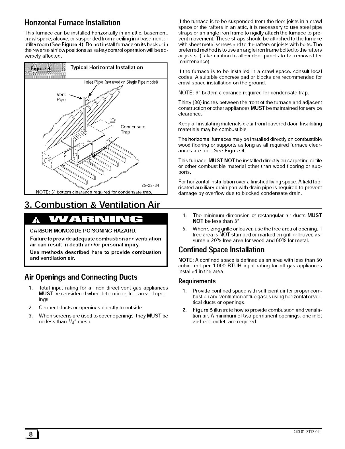
Horizontal Furnace Installation
This furnace can be installed horizontally in an attic, basement,
crawl space, alcove, or suspended from a ceiling in a basement or
utility room (See Figure 4). Do not install furnace on its back or in
the reverse airflow positions as safety control operation will be ad-
versely affected.
Typical Horizontal Installation
Inlet Pipe (notusedon SinglePipemodel)
Vent
Pipe
Condensate
Trap
25-23-34
NOTE: 5" bottom clearance required for condensate trap.
If the furnace is to be suspended from the floor joists in a crawl
space or the rafters in an attic, it is necessary to use steel pipe
straps or an angle iron frame to rigidly attach the furnace to pre-
vent movement. These straps should be attached to the furnace
with sheet metal screws and to the rafters or joists with bolts. The
preferred method is to use an angle iron frame bolted to the rafters
or joists. (Take caution to allow door panels to be removed for
maintenance)
If the furnace is to be installed in a crawl space, consult local
codes. A suitable concrete pad or blocks are recommended for
crawl space installation on the ground.
NOTE: 6" bottom clearance required for condensate trap.
Thirty (30) inches between the front of the furnace and adjacent
construction or other appliances MUST be maintained for service
clearance.
Keep all insulating materials clear from louvered door. Insulating
materials may be combustible.
The horizontal furnaces may be installed directly on combustible
wood flooring or supports as long as all required furnace clear-
ances are met. See Figure 4.
This furnace MUST NOT be installed directly on carpeting or tile
or other combustible material other than wood flooring or sup-
ports.
For horizontal installation over a finished living space. A field fab-
ricated auxiliary drain pan with drain pipe is required to prevent
damage by overflow due to blocked condensate drain.
3. Combustion & Ventilation Air
CARBON MONOXIDE POISONING HAZARD.
Failure to provide adequate combustion and ventilation
air can result in death and/or personal injury.
Use methods described here to provide combustion
and ventilation air.
Air Openings and Connecting Ducts
1. Total input rating for all non direct vent gas appliances
MUST be considered when determining free area of open-
ings.
2. Connect ducts or openings directly to outside.
3. When screens are used to cover openings, they MUST be
no less than 1/4" mesh.
4. The minimum dimension of rectangular air ducts MUST
NOT be less than 3".
5. When sizing grille or louver, use the free area of opening. If
free area is NOT stamped or marked on grill or louver, as-
sume a 20% free area for wood and 60% for metal.
Confined Space Installation
NOTE: A confined space is defined as an area with less than 50
cubic feet per 1,000 BTUH input rating for all gas appliances
installed in the area.
Requirements
1. Provide confined space with sufficient air for proper com-
bustion and ventilation of flue gases using horizontal or ver-
tical ducts or openings.
2. Figure 5 illustrate how to provide combustion and ventila-
tion air. A minimum of two permanent openings, one inlet
and one outlet, are required.
[_ 440 01 211302
Gas
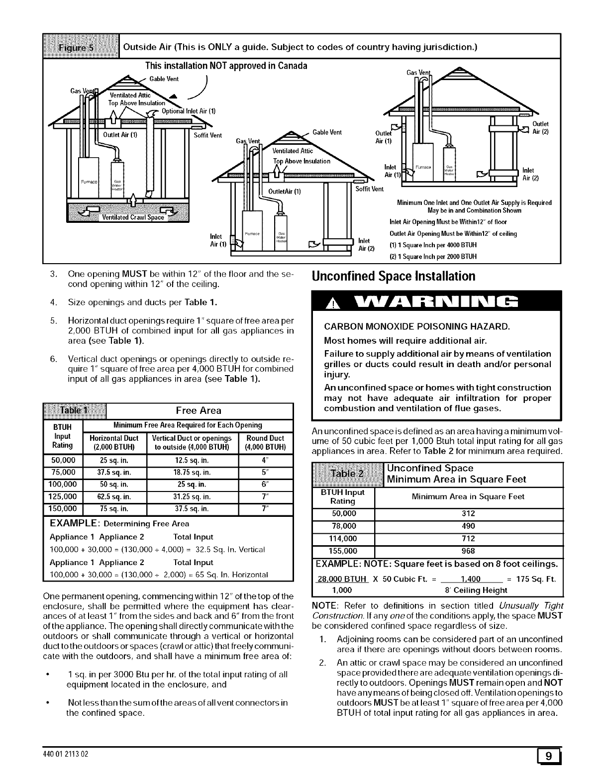
Outside Air (This is ONLY a guide. SubJect to codes of country havingjurisdiction.)
This installation NOTapproved in Canada
Gable Vent_b. J
(1)
Soffit Vent Gable Vent
Ga Air (1)
Outlet
Air (2)
Inlet
Air (1)
AboveInsulation
Air (1) Soffit Vent
_Inlet
J_f I _ _ 1"_ Air (2)
Inlet Inlet
Air (2)
MinimumOne Inlet and OneOutlet Air Supplyis Required
May be in and Combination Shown
Inlet Air Opening Must be Within12" of floor
Outlet Air Opening Must be Within12" of ceiling
(1) 1SquareInch per 4000BTUH
(2) 1SquareInch per 2000BTUH
3. One opening MUST be within 12" of the floor and the se-
cond opening within 12" of the ceiling. Unconfined Space Installation
4.
5.
Size openings and ducts per Table 1.
Horizontal duct openings require 1" square of free area per
2,000 BTUH of combined input for all gas appliances in
area (see Table 1).
Vertical duct openings or openings directly to outside re-
quire 1" square of free area per 4,000 BTUH for combined
input of all gas appliances in area (see Table 1).
Free Area
BTUH MinimumFreeArea Requiredfor Each Opening
Input HorizontalDuct VerticalDuctor openings Round Duct
Rating (2,000BTUH) to outside(4,000BTUH) (4,000BTUH)
50,000 25 sq, in. 12.5sq. in, 4"
75,000 37,5 sq. in. 18.75sq. in. 5"
100,000 50 sq, in. 25 sq. in. 6"
125,000 62,5 sq. in. 31,25sq. in. 7"
150,000 75 sq, in. 37.5 sq. in, 7"
EXAMPLE: Determining Free Area
Appliance 1 Appliance 2 Total Input
100,000 + 30,000 = (130,000 +4,000) = 32.5 Sq. In. Vertical
Appliance 1 Appliance 2Total Input
100,000 + 30,000 = (130,000 +2,000) = 65 Sq. In. Horizontal
One permanent opening, commencing within 12" of the top of the
enclosure, shall be permitted where the equipment has clear-
ances of at least 1" from the sides and back and 6" from the front
of the appliance. The opening shall directly communicate with the
outdoors or shall communicate through a vertical or horizontal
duct to the outdoors or spaces (crawl or attic) that freely communi-
cate with the outdoors, and shall have a minimum free area of:
• 1 sq. in per 3000 Btu per hr. of the total input rating of all
equipment located in the enclosure, and
• Not less than the sum ofthe areas of all vent connectors in
the confined space.
CARBON MONOXIDE POISONING HAZARD.
Most homes will require additional air.
Failure to supply additional air by means of ventilation
grilles or ducts could result in death and/or personal
injury.
An unconfined space or homes with tight construction
may not have adequate air infiltration for proper
combustion and ventilation of flue gases.
An unconfined space is defined as an area having a minimum vol-
ume of 50 cubic feet per 1,000 Btuh total input rating for all gas
appliances in area. Refer to Table 2 for minimum area required.
BTUH Input
Rating
50,000
78,000
114,000
155,000
Minimum Area in Square Feet
312
490
712
968
EXAMPLE: NOTE: Square feet is based on 8 foot ceilings.
28,000BTUH X 50CubicFt, = 1,400 = 175Sq, Ft.
1,000 8' Ceiling Height
NOTE: Refer to definitions in section titled Unusually #_Tht
Construction. If any oneof the conditions apply, the space MUST
be considered confined space regardless of size.
1. Adjoining rooms can be considered part of an unconfined
area if there are openings without doors between rooms.
2. An attic or crawl space may be considered an unconfined
space provided there are adequate ventilation openings di-
rectly to outdoors. Openings MUST remain open and NOT
have any means of being closed off. Ventilation openings to
outdoors MUST be at least 1" square of free area per 4,000
BTUH of total input rating for all gas appliances in area.
44001 211302 E_I
3. Installairintakeaminimumof12"abovemaximumsnow
levelandclearofanyobstruction.Ductorventilationopen-
ingrequiresonesquareinchoffreeareaper4,000BTUH
oftotalinputratingforallgasappliancesinarea.
4. AirinletMUSTbescreenedwithnotlessthan114"mesh
screen.
Unusually Tight Construction
In unconfined spaces, infiltration may be adequate to provide air
for combustion, ventilation and dilution of flue gases. However, in
buildings with unusually tight construction, additional air MUST
be provided using the methods described in section titled Con-
fined Space Installation:
Unusually tight construction is defined as: Construction with
1. Walls and ceilings exposed to the outside have a continu-
ous, sealed vapor barrier. Openings are gasketed or
sealed and
2,
3.
Doors and opeRable windows are weather stripped and
Other openings are caulked or sealed. These include joints
around window and door frames, between sole plates and
floors, between wall-ceiling joints, between wall panels, at
penetrations for plumbing, electrical and gas lines, etc.
Ventilation Air
Some provincial codes and local municipalities require ventilation
or make-up air be brought into the conditioned space as replace-
ment air. Whichever method is used, the mixed return air temper-
ature across the heat exchanger MUST not fall below 60 ° F or flue
gases will condense in the heat exchanger. This will shorten the
life of the heat exchanger and possibly void your warranty.
Venting and Combustion Air Check
The following information is supplied to allow the installer to make
adjustments to the setup of existing appliances, IF REQUIRED,
based on good trade practices, local codes, and good judgement
of the installer. Manufacturer does NOT take responsibility for
modifications made to existing equipment.
NOTE: If this installation replaces an existing furnace from a
commonly vented system, the original venting system may no
longer be sized to properly vent the attached appliances. An im-
properly sized venting system may cause the formation of con-
densate in the vent or the leakage or spillage of vent gases. To
make sure there is adequate combustion air for all appliances,
MAKE THE FOLLOWING CHECK.
1. Seal any unused openings in the venting system.
Visually inspect the venting system for proper size and hor-
izontal pitch to ensure there is no blockage or restriction,
leakage, corrosion or other deficiencies which could cause
an unsafe condition.
3. Insofar as is practical, close all doors and windows and all
doors between the space in which the appliance(s) remain-
ing connected to the venting system are located and other
spaces of the building.
4. Turn on clothes dryers and any appliance not connected to
the venting system. Turn on any exhaust fans, such as
range hoods and bathroom exhausts, so they will operate
at maximum speed. Do not operate a summer exhaust fan.
Close fireplace dampers.
5. Follow the lighting instructions for each appliance being in-
spected. Adjust thermostat so appliance(s) will operate
continuously.
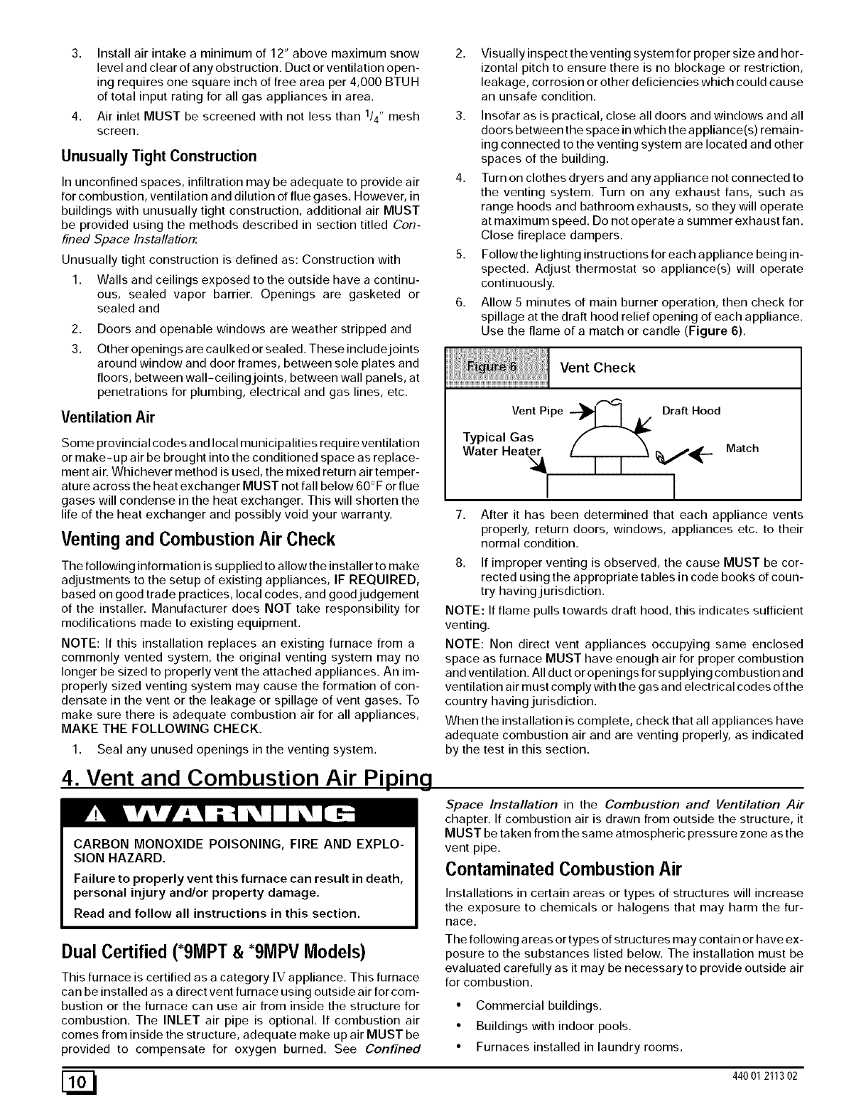
6. Allow 5 minutes of main burner operation, then check for
spillage at the draft hood relief opening of each appliance.
Use the flame of a match or candle (Figure 6).
Vent Check
VentPipe --_1 I A/ Draft Hood
Typical Gas
Water Heater _,,/_-
I l
7.
Match
After it has been determined that each appliance vents
properly, return doors, windows, appliances etc. to their
normal condition.
8. If improper venting is observed, the cause MUST be cor-
rected using the appropriate tables in code books of coun-
try having jurisdiction.
NOTE: If flame pulls towards draft hood, this indicates sufficient
venting.
NOTE: Non direct vent appliances occupying same enclosed
space as furnace MUST have enough air for proper combustion
and ventilation. All duct or openings for supplying combustion and
ventilation air must comply with the gas and electrical codes of the
country having jurisdiction.
When the installation is complete, check that all appliances have
adequate combustion air and are venting properly, as indicated
by the test in this section.
4. Vent and Combustion Air Pi igLEg
CARBON MONOXIDE POISONING, FIRE AND EXPLO-
SION HAZARD.
Failure to properly vent this furnace can result in death,
personal injury and/or property damage.
Read and follow all instructions in this section.
Dual Certified (*9MPT &*9MPV Models)
This furnace is certified as a category [V appliance. This furnace
can be installed as a direct vent furnace using outside air for com-
bustion or the furnace can use air from inside the structure for
combustion. The INLET air pipe is optional. If combustion air
comes from inside the structure, adequate make up air MUST be
provided to compensate for oxygen burned. See Confined
Space Installation in the Combustion and Ventilation Air
chapter. If combustion air is drawn from outside the structure, it
MUST be taken from the same atmospheric pressure zone as the
vent pipe.
Contaminated Combustion Air
Installations in certain areas or types of structures will increase
the exposure to chemicals or halogens that may harm the fur-
Race.
The following a reas or types of structures may contain or have ex-
posure to the substances listed below. The installation must be
evaluated carefully as it may be necessary to provide outside air
for combustion.
• Commercial buildings.
• Buildings with indoor pools.
• Furnaces installed in laundry rooms.
[_ 440 01 211302
• Furnacesinstalledinhobbyorcraftrooms.
• Furnacesinstallednearchemicalstorageareas.
• Permanentwavesolutionsforhair.
• Chlorinatedwaxesandcleaners.
• Chlorinebasedswimmingpoolchemicals.
• Watersofteningchemicals.
• De-icingsaltsorchemicals.
• Carbontetrachloride.
• Halogentyperefrigerants.
• Cleaningsolvents(suchasperchloroethylene).
• Printinginks,paintremovers,varnishes,etc.
• Hydrochloricacid.
• SulfuricAcid.
• Solventcementsandglues.
• Antistaticfabricsoftenersforclothesdryers.
• Masonryacidwashingmaterials.
Vent and Combustion Air Piping Guidelines
NOTE: All vent piping MUST be installed in compliance with local
codes or ordinances, these instructions, good trade practices,
and codes of country having jurisdiction.
1. Determine the best routing and termination for the vent
pipe and air inlet pipe by referring to all of the instructions
and guidelines in this Section.
2. Determine the size required for the vent pipe and air inlet
pipe.
3. Loosely assemble all venting parts without adhesive (pipe
joint cement) for correct fit before final assembly.
Use of vertical piping is preferred because there will be
some moisture in the flue gases that may condense as it
leaves the vent pipe (See Special Instruction For Horizon-
tal Vents).
5. The vertical vent pipe MUST be supported so that no
weight is allowed to rest on the combustion blower.
6. Exhaust vent piping or air inlet piping diameter MUST NOT
be reduced.
All exhaust vent piping from the furnace to termination
MUST slope upwards. A minimum of 1/4" per foot of run is
required to properly return condensate to the furnace drain
system.
Use DWV type long radius elbows whenever possible, as
they provide for the minimum slope on horizontal runs and
they provide less resistance in the vent system. If DWV el-
bows cannot be used, use two, 45 ° elbows when possible.
On horizontal runs the elbows can be slightly misaligned to
provide the correct slope.
9. All horizontal pipe runs MUST be supported at least every
five feet with galvanized strap or other rust resistant materi-
al. NO sags or dips are permitted.
10. All vertical pipe runs MUST be supported every six feet
where accessible.
11. The maximum pipe length is 40' total in the inlet oroutlet
side of the system. Up to five, 90 ° elbows can be used on
the inlet orthe outlet. With the Concentric Vent Termination
Kits (NAHAOOICV or NAHAOO2CV), the maximum pipe
length is 35' with 4 90 ° elbows. If more elbows are required,
reduce the length of both the inlet and exhaust pipes 5' for
each additional elbow used. (See Table 3 or Table 4).
12. The minimum pipe run length is 2'.
13. The piping can be run in the same chase or adJacent to sup-
ply or vent pipe for water supply or waste plumbing. It can
also be run in the same chase with a vent from another 90+
furnace.
NOTE: In NO case can the piping be run in a chase where
temperatures can exceed 140 ° F. or where radiated heat
from adjacent surfaces would exceed 140 ° F.
14. The vent outlet MUST be installed to terminate in the same
atmospheric pressure zone as the combustion air inlet.
15. The vent system can be installed in an existing unused
chimney provided that:
• Both the exhaust vent and air intake run the length of the
chimney.
• No other gas fired appliance or fireplace (solid fuel) is
vented into the chimney.
• The top of the chimney MUST be sealed flush or crowned
up to seal against rain or melting snow so ONLY the piping
protrudes.
• The termination clearances shown in Figure 7 are main-
tained.
16. Furnace applications with vertical vents requiring vent di-
ameter increaser fittings must have increaser fittings
installed in vertical portion of the vent. Condensate will be
trapped in the vent if the vent diameter is increased prior to
having an elbow turned upward. This could cause nui-
sance tripping of the pressure switch.
Piping Insulation Guidelines
NOTE: Use closed cell, neoprene insulation or equivalent. If Fi-
berglass or equivalent insulation is used it must have a vapor bar-
rier. Use R values of 7 up to 10', R-11 if exposure exceeds 10'. If
Fiberglass insulation is used, exterior to the structure, the pipe
MUST be boxed in and sealed against moisture.
1. .When the vent or combustion air pipe height above the
roof exceeds 30", or if an exterior vertical riser is used on a
horizontal vent to get above snow levels, the exterior por-
tion MUST be insulated.
2. When combustion air inlet piping is installed above a sus-
pended ceiling, the pipe MUST be insulated with moisture
resistant insulation such as Armaflex or other equivalent
type of insulation.
3. Insulate combustion air inlet piping when run in warm, hu-
mid spaces such as basements.
Sizing Combustion Air and Vent Pipe
Consult Table 3 or Table 4 to select the proper diameter exhaust
and combustion air piping. Exhaust and combustion air piping is
sized for each furnace Btuh size based on total lineal vent length
(on inlet or outlet side), and number of 90 ° elbows required.
1. Double Pipe Installation-If installing as a direct-vent ap-
pliance, consult Table 4 to select the proper diameter ex-
haust and combustion air piping. Exhaust and combustion
air piping is sized for each furnace Btuh size based on total
lineal vent length (on inlet oroutlet side), and number of 90 °
elbows required.
44001 211302 E_
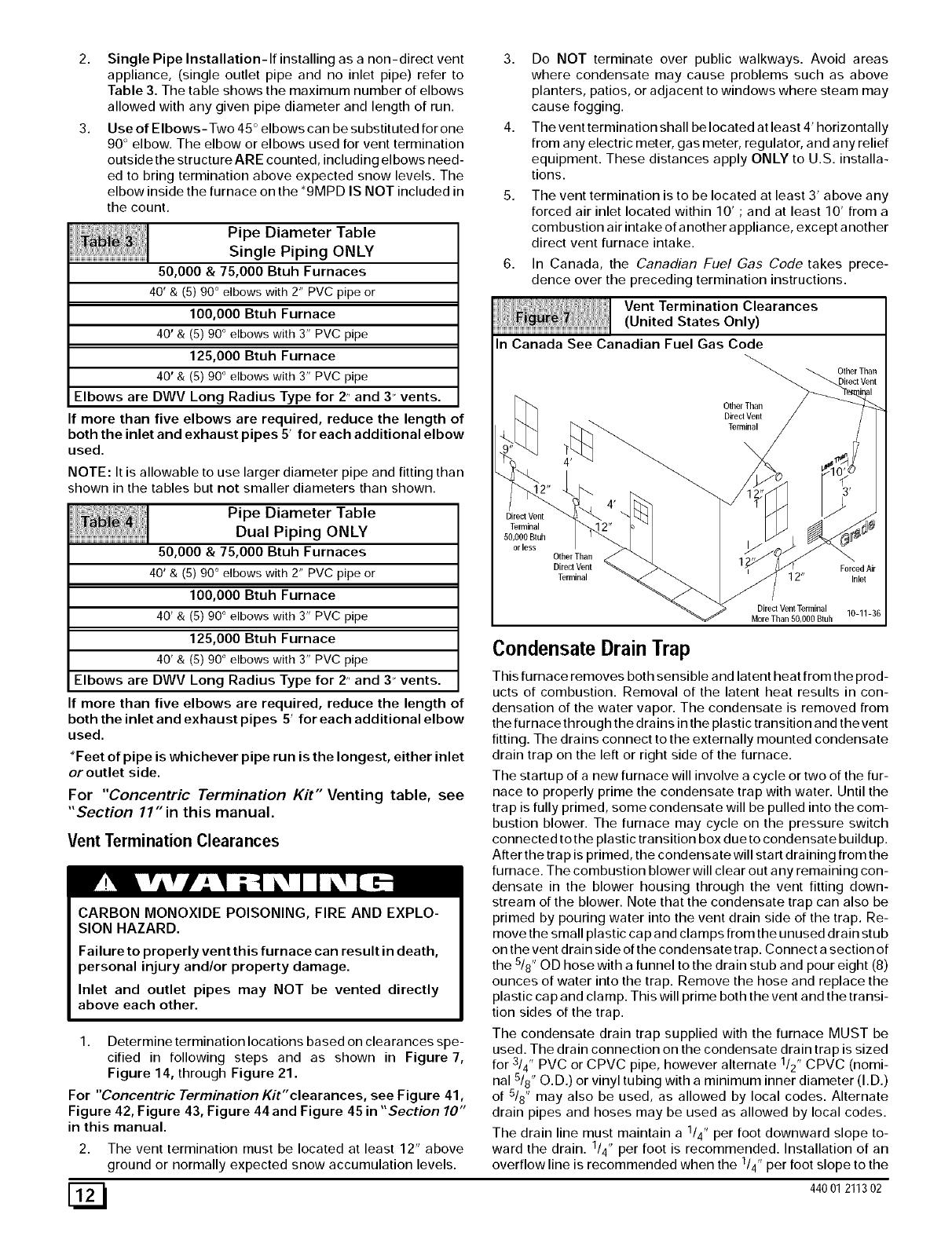
2. SinglePipeInstallation-If installing as a non-direct vent
appliance, (single outlet pipe and no inlet pipe) refer to
Table 3. The table shows the maximum number of elbows
allowed with any given pipe diameter and length of run.
3. Use of Elbows-Two 45 ° elbows can be substituted forone
90 ° elbow. The elbow or elbows used for vent termination
outside the structure ARE counted, including elbows need-
ed to bring termination above expected snow levels. The
elbow inside the furnace on the *9MPD IS NOT included in
the count.
Pipe Diameter Table
Single Piping ONLY
50,000 &75,000 Btuh Furnaces
40' & (5) 90 ° elbows with 2" PVC pipe or
100,000 Btuh Furnace
40' & (5) 90 ° elbows with 3" PVC pipe
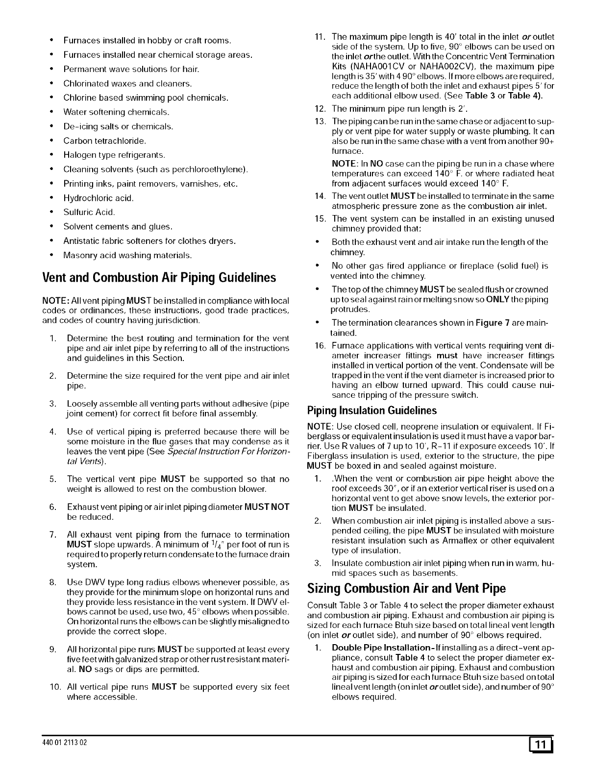
3. Do NOT terminate over public walkways. Avoid areas
where condensate may cause problems such as above
planters, patios, or adjacent to windows where steam may
cause fogging.
4. The vent termination shall be located at least 4' horizontally
from any electric meter, gas meter, regulator, and any relief
equipment. These distances apply ONLY to U.S. installa-
tions.
The vent termination is to be located at least 3' above any
forced air inlet located within 10' ; and at least 10' from a
combustion air intake of another appliance, except another
direct vent furnace intake.
In Canada, the Canadian Fuel Gas Code takes prece-
dence over the preceding termination instructions.
Vent Termination Clearances
(United States Only)
125,000 Btuh Furnace
40' & (5) 90 ° elbows with 3" PVC pipe
Elbows are DWV Long Radius Type for 2" and 3" vents.
If more than five elbows are required, reduce the length of
both the inlet and exhaust pipes 5' for each additional elbow
used.
NOTE: It is allowable to use larger diameter pipe and fitting than
shown in the tables but not smaller diameters than shown.
Pipe Diameter Table
Dual Piping ONLY
50,000 & 75,000 Btuh Furnaces
40' & (5) 90 ° elbows with 2" PVC pipe or
100,000 Btuh Furnace
40' & (5) 90 ° elbows with 3" PVC pipe
125,000 Btuh Furnace
40' & (5) 90 ° elbows with 3" PVC pipe
Elbows are DWV Long Radius Type for 2" and 3" vents.
If more than five elbows are required, reduce the length of
both the inlet and exhaust pipes 5' for each additional elbow
used.
*Feet of pipe is whichever pipe run is the longest, either inlet
or outlet side.
For "Concentric Termination Kit" Venting table, see
"Section 11" in this manual.
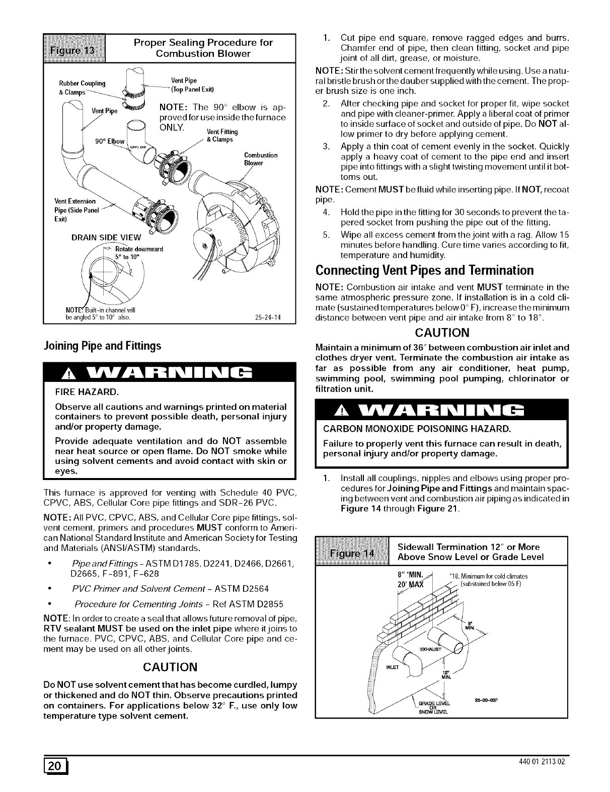
Vent Termination Clearances
CARBON MONOXIDE POISONING, FIRE AND EXPLO-
SION HAZARD.
Failure to properly vent this furnace can result in death,
personal injury and/or property damage.
Inlet and outlet pipes may NOT be vented directly
above each other.
1. Determine termination locations based on clearances spe-
cified in following steps and as shown in Figure 7,
Figure 14, through Figure 21.
For "Concentric Termination Kit" clearances, see Figure 41,
Figure 42, Figure 43, Figure 44 and Figure 45 in "Section 10"
in this manual.
2. The vent termination must be located at least 12" above
ground or normally expected snow accumulation levels.
In Canada See Canadian Fuel Gas Code
Direct Vent
Terminal
50,000 Btuh
orless
Other Than
DirectVent
Terminal
OtherThan
OtherThan
Direcl Vent Forced Air
Terminal 12" Inlm
Direct Vent Terminal 10-11-36
MoreThan 50,000 Btuh
Condensate DrainTrap
This furnace removes both sensible and latent heat from the prod-
ucts of combustion. Removal of the latent heat results in con-
densation of the water vapor. The condensate is removed from
the furnacethrough the drains in the plastic transition and thevent
fitting. The drains connect to the externally mounted condensate
drain trap on the left or right side of the furnace.
The startup of a new furnace will involve a cycle or two of the fur-
nace to properly prime the condensate trap with water. Until the
trap is fully primed, some condensate will be pulled into the com-
bustion blower. The furnace may cycle on the pressure switch
connected to the plastic transition box due to condensate buildup.
After the trap is primed, the condensate will start draining from the
furnace. The combustion blower will clear out any remaining con-
densate in the blower housing through the vent fitting down-
stream of the blower. Note that the condensate trap can also be
primed by pouring water into the vent drain side of the trap. Re-
move the small plastic cap and clamps from the unused drain stub
on the vent drain side of the condensatetrap. Connect a section of
the 5/8" OD hose with a funnel to the drain stub and pour eight (8)
ounces of water into the trap. Remove the hose and replace the
plastic cap and clamp. This will prime both the vent and the transi-
tion sides of the trap.
The condensate drain trap supplied with the furnace MUST be
used. The drain connection on the condensate drain trap is sized
for 3/4" PVC or CPVC pipe, however alternate 1/2" CPVC (nomi-
nal 5/8" O.D.) or vinyl tubing with a minimum inner diameter (I.D.)
of 5/8" may also be used, as allowed by local codes. Alternate
drain pipes and hoses may be used as allowed by local codes.
The drain line must maintain a 1/4" per foot downward slope to-
ward the drain. 1/4" per foot is recommended. Installation of an
overflow line is recommended when the 1/4" per foot slope to the
[_ 440 01 211302
condensatedraincannotbemaintained.SeeFigure1forproper
routingandinstallationoftheoverflow.
DONOTtrapthedrainlineinanyotherlocationthanatthecon-
densatedraintrapsuppliedwiththefurnace.
FROZEN AND BURST WATER PIPE HAZARD.
If a condensate pump is installed, a plugged condensate
drain or a failed pump may cause the furnace to shut
down. Do not leave the home unattended during freezing
weather without turning off water supply and draining
water pipes or otherwise protecting against the risk of
frozen pipes.
Failure to do so may result in burst water pipes, serious
property damage and/or personal injury.
If possible DO NOT route the drain line where it may freeze. The
drain line must terminate at an inside drain to prevent freezing of
the condensate and possible property damage.
1. A condensate sump pump MUST be used if required by lo-
cal codes, or if no indoor floor drain is available. The con-
densate pump must be approved for use with acidic
condensate.
A plugged condensate drain line or a failed condensate
pump will allow condensate to spill. If the furnace is
installed where a condensate spill could cause damage, it
is recommended that an auxiliary safety switch be installed
to prevent operation of the equipment in the event of pump
failure or plugged drain line. If used, an auxiliary safety
switch should be installed in the R circuit (low voltage)
ONLY.
If the auxiliary switch in the condensate pump is used, the
furnace may shut down due to a blocked condensate line or
failed pump. To prevent frozen water pipes see the "Frozen
Water Pipe Hazard" section on Page 4 of this manual.
Condensate Drain Trap Freeze Protection
Special precautions MUST be made if installing furnace in an
area which may drop below freezing. This ca n ca use improper op-
eration or damage to the equipment. If the the furnace environ-
ment has the potential of freezing, the drain trap and drain line
must be protected. Use 3 to 6 watt per foot at 115 volt, 40 ° F self-
regulating shielded and waterproof heat tape. Wrap the drain trap
and drain line with the heat tape and secure with the ties. Follow
the heat tape manufacturer's recommendations.
44001 211302 [_
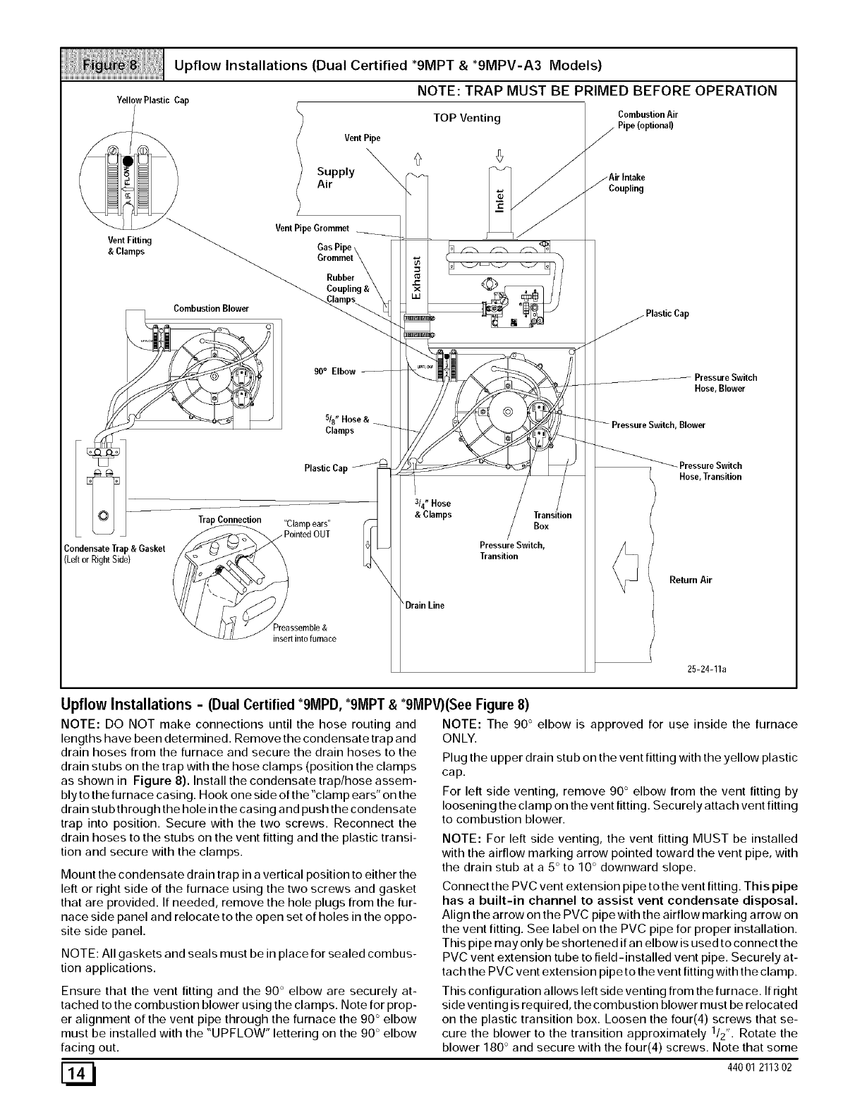
Upflow Installations (Dual Certified *9MPT & *9MPV-A3 Models)
NOTE: TRAP MUST BE PRIMED BEFORE OPERATION
YellowPlastic Cap
Vent Fitting
&Clamps
CombustionBlower
Condensate Trap& Gasket
(Leftor RightSide)
VentPipe
Supply
Air
VentPipe Grommet
Rubber
90°Elbow
5/8" Hose&
Clamps
Plastic Cap
Trap Connection "Clamp ears"
ointed OUT
"_ /f// _?reassemble&
insert into furnace
TOP Venting
©
314" Hose
& Clamps Transition
Box
Pressure Switch,
Transition
\DrainLine
Combustion Air
Pipe (optional)
Coupling
Hose, Blower
Blower
Hose,Transition
Return Air
25-24-11a
Upflow Installations - (Dual Certified *9MPD, *9MPT &*9MPV)(See Figure 8)
NOTE: DO NOT make connections until the hose routing and
lengths have been determined. Remove the condensate trap and
drain hoses from the furnace and secure the drain hoses to the
drain stubs on the trap with the hose clamps (position the clamps
as shown in Figure 8). Install the condensate trap/hose assem-
bly to the furnace casing. Hook one side of the "clamp ears" on the
drain stub through the hole in the casing and push the condensate
trap into position. Secure with the two screws. Reconnect the
drain hoses to the stubs on the vent fitting and the plastic transi-
tion and secure with the clamps.
Mount the condensate drain trap in a vertical position to either the
left or right side of the furnace using the two screws and gasket
that are provided. If needed, remove the hole plugs from the fur-
nace side panel and relocate to the open set of holes in the oppo-
site side panel.
NOTE: All gaskets and seals must be in place for sealed combus-
tion applications.
Ensure that the vent fitting and the 90 ° elbow are securely at-
tached to the combustion blower using the clamps. Note for prop-
er alignment of the vent pipe through the furnace the 90 ° elbow
must be installed with the "UPFLOW" lettering on the 90 ° elbow
facing out.
NOTE: The 90 ° elbow is approved for use inside the furnace
ONLY.
Plug the upper drain stub on the vent fitting with the yellow plastic
cap.
For left side venting, remove 90 ° elbow from the vent fitting by
loosening the clamp on the vent fitting. Securely attach vent fitting
to combustion blower.
NOTE: For left side venting, the vent fitting MUST be installed
with the airflow marking arrow pointed toward the vent pipe, with
the drain stub at a 5 ° to 10 ° downward slope.
Connect the PVC vent extension pipe to the vent fitting. This pipe
has a built-in channel to assist vent condensate disposal.
Align the arrow on the PVC pipe with the airflow marking arrow on
the vent fitting. See label on the PVC pipe for proper installation.
This pipe may only be shortened if an elbow is used to connect the
PVC vent extension tube to field-installed vent pipe. Securely at-
tach the PVC vent extension pipe to the vent fitting with the clamp.
This configuration allows left side venting from the furnace. If right
side venting is required, the combustion blower must be relocated
on the plastic transition box. Loosen the four(4) screws that se-
cure the blower to the transition approximately 1/2". Rotate the
blower 180 ° and secure with the four(4) screws. Note that some
[_ 440 01 211302
combustionblowershaveplasticspacersonthemountinglegsof
theblowerlocatedatthe6and12o'clockpositions(blowersnout
totheleftorright)thatarerequiredforproperfitupoftheblowerto
thetransition.Usecautiontonotovertightenthescrewstopre-
ventstrippingoutoftheplasticmountingholes.
NOTE:Forrightsideventing,theventfittingMUSTbeinstalled
withtheairflowmarkingarrowpointedtowardtheventpipe,with
thedrainstubata5°to10°downwardslope.(SeeFigure9)
Plugtheupperdrainstubontheventfittingwiththeyellowplastic
cap.
ConnectthePVCventextensionpipetotheventfitting.Thispipe
hasabuilt-inchannelto assistventcondensatedisposal.
AlignthearrowonthePVCpipewiththeairflowmarkingarrowon
theventfitting.SeelabelonthePVCpipeforproperinstallation.
Thispipemayonlybeshortenedifanelbowisusedtoconnectthe
PVCventextensiontubetofield-installedventpipe.Securelyat-
tachthePVCventextensionpipetotheventfittingwiththeclamp.
Forleftsidemountedcondensatetrap,connectthe3/4"ODrub-
berhosewiththe90°bendtothelargedrainstubontheconden-
satetrapand secure with a3/4" clamp.
Route the hose to the drain stub on the bottom of the plastic transi-
tion box. Cut off excess hose and discard. Connect the hose to the
drain stub on the transition and secure with a 3/4" clamp,
For right side mounted condensate trap, connect the 3/4" OD rub-
ber hose with the 90 ° bend to the bottom of the plastic transition
box and secure with a 3/4" clamp.
Route the hose to the large drain stub on the condensate trap. Cut
off excess hose and discard. Connect the hose to the drain stub
on the condensate trap and secure with a 3/4" clamp.
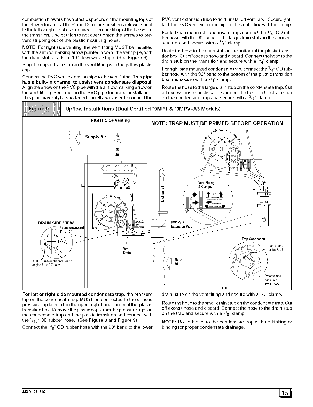
Upflow Installations (Dual Certified *9MPT & *91VlPV-A3 Models)
RIGHTSideVenting NOTE: TRAP MUST BE PRIMED BEFORE OPERATION
DRAIN SIDE VIEW
Rotatedownward
angled 5° to 10° also.
Supply Air '_
Vent
Drain
PVC Vent
Return
Air
Vent Fitting
&Clamps
TrapConnection
"Clamp ears"
ointed OUT
eassernble
d insert
into furnace
25-24-05
For left or right side mounted condensate trap, the pressure
tap on the condensate trap MUST be connected to the unused
pressure tap located on the upper right hand corner of the plastic
transition box. Remove the plastic caps from the pressure taps on
the condensate trap and the plastic transition and connect with
the 5116" OD rubber hose. (See Figure 8 and Figure 9)
Connect the 518" OD rubber hose with the 90 ° bend to the lower
drain stub on the vent fitting and secure with a 5/8" clamp.
Route the hose to the small drain stub on the condensate trap. Cut
off excess hose and discard. Connect the hose to the drain stub
on the trap and secure with a 5/8" clamp.
NOTE: Route hoses to the condensate trap with no kinking or
binding for proper condensate drainage.
44001 211302 [_1
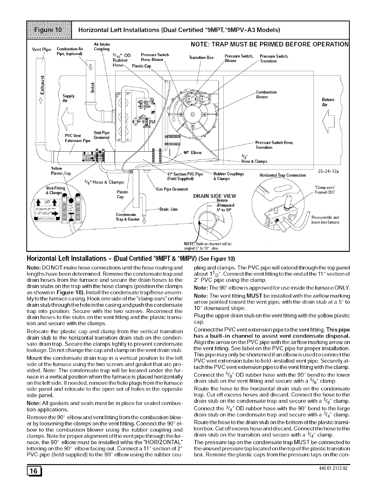
HorizontalLeftInstallations (Dual Certified *9MPT,*9MPV-A3 Models)
Air Intake
Combustion Air
Pipe, (optional) 5/'16" OD Pressure Switch
Rubber Hose, Blower
Plastic Cap
NOTE: TRAP MUST BE PRIMED BEFORE OPERATION
Transition Box Pressure Switch, Pressure Switch,
Blower
Supply
Air
Yellow
Plastic
Vent Pipe
PVCVent Grommet
ExtensionPipe
Elbow
Blower
Transition
314"
Hose & Clamps
518" Hose &Clamps
Plastic
Cap
Condensate
Trap &Gasket
ipe plings
(Field Supplied) &Clamps
DRAIN SIDE VIEW
Rotate
ward
angled5° to10° also.
Connection
Horizontal Left Installations - (Dual Certified "9MPT &"9MPV) (See Figure 10)
Note: DO NOT make hose connections until the hose routing and
lengths have been determined. Remove the condensate trap and
drain hoses from the furnace and secure the drain hoses to the
drain stubs on the trap with the hose clamps (position the clamps
as shown in Figure 10). Install the condensate trap/hose assem-
bly to the furnace casing. Hook one side of the "clamp ears" on the
drain stubthrough the hole in the casing and push the condensate
trap into position. Secure with the two screws. Reconnect the
drain hoses to the stubs on the vent fitting and the plastic transi-
tion and secure with the clamps.
Relocate the plastic cap and clamp from the vertical transition
drain stub to the horizontal transition drain stub on the conden-
sate drain trap. Secure the clamps tightly to prevent condensate
leakage. Do not change the cap and clamp on the vent drain stub.
Mount the condensate drain trap in a vertical position to the left
side of the furnace using the two screws and gasket that are pro-
vided. Note: The condensate trap will be located under the fur-
nace in a vertical position when the furnace is placed horizontally
on the left side. If needed, remove the hole plugs from the furnace
side panel and relocate to the open set of holes in the opposite
side panel.
Note: All gaskets and seals must be in place for sealed combus-
tion applications.
Remove the 90 ° el bow and vent fitting from the combustion blow-
er by loosening the clamps on the vent fitting. Connect the 90 ° el-
bow to the combustion blower using the rubber coupling and
cla raps. Note for proper alignment of the vent pipe through the fur-
nace, the 90 ° elbow must be installed withe the "HORIZONTAL"
lettering on the 90 ° elbow facing out. Connect a 11" section of 2"
PVC pipe (field supplied) to the 90 ° elbow using the rubber cou-
Return
Air
25-24-12a
"Clamp ears"
_ Preassembleand
insertinto furnace
piing and clamps. The PVC pipe will extend through the top panel
1 ,
about 1 /2' •Connect the vent fitting to the end of the 11' section of
2" PVC pipe using the clamp.
Note: The 90 ° elbow is approved for use inside the furnace ON LY.
Note: The vent fitting MUST be installed with the airflow marking
arrow pointed toward the vent pipe, with the drain stub at a 5 ° to
10 ° downward slope.
Plug the upper drain stub on the vent fitting with the yellow plastic
cap.
Connect the PVC vent extension pipe to the vent fitting. This pipe
has a built-in channel to assist vent condensate disposal.
Align the arrow on the PVC pipe with the airflow marking arrow on
the vent fitting. See label on the PVC pipe for proper installation.
This pipe may only be shortened if an elbow is used to connect the
PVC vent extension tube to field-installed vent pipe. Securely at-
tach the PVC vent extension pipe to the vent fitting with the clamp.
Connect the 5/8" OD rubber hose with the 90 ° bend to the lower
drain stub on the vent fitting and secure with a 5/8" clamp.
Route the hose to the horizontal drain stub on the condensate
trap. Cut off excess hoses and discard. Connect the hose to the
drain stub on the condensate trap and secure with a 5/8" clamp.
Connect the 3/4" OD rubber hose with the 90 ° bend to the large
drain stub on the condensate trap and secure with a 3/4" clamp.
Route the hose to the drain stub on the bottom of the plastic tra nsi-
tion box. Cut off excess hose and discard. Connect the hose to the
drain stub on the transition and secure with a 3/4" clamp.
The pressure tap on the condensate trap MUST be connected to
the unused pressure tap located on the top of the plastic transition
box. Remove the plastic caps from the pressure taps on the con-
[_ 440 01 211302
densatetrap and the plastic transition and connect with the 5/16"
OD rubber hose.
Note: This will require drilling a 5/16" OD hole in the furnace cas-
ing next to the condensate trap.
Note: Ensure hoses maintain a downward slope to the conden-
sate trap with no kinking or binding for proper condensate drain-
age.
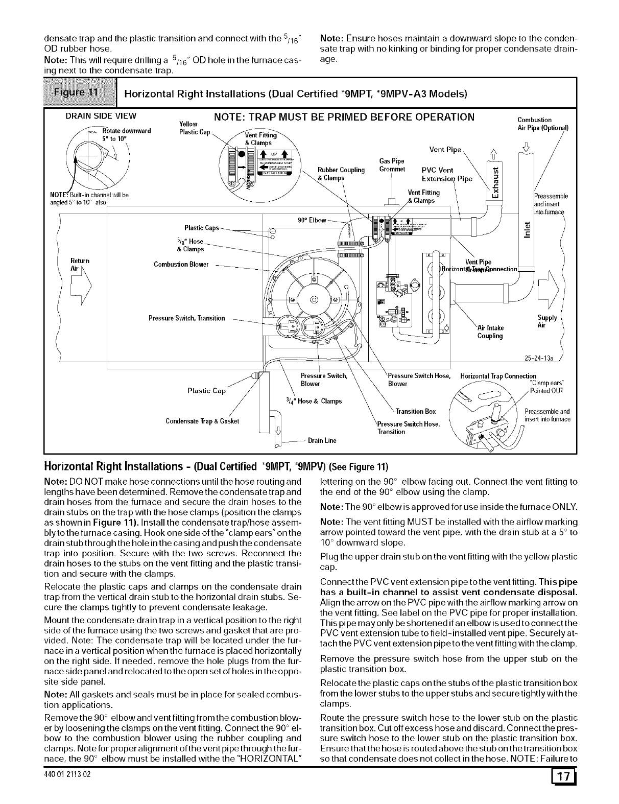
Horizontal Right Installations (Dual Certified *9MPT, *9MPV-A3 Models)
DRAIN SIDE VIEW
//_Rotate downward
NOTE:_
angled 5° to 10° also.
NOTE: TRAP MUST BE PRIMED BEFORE OPERATION Combustion
YellowPlastic Air Pipe
Cap
Vent Pi z_
Gas Pipe
/ _ /_ Rubber Coupling Grommet PVC Vent
ps Vent Fitting Preassemble
Return
&Clamps
Combustion Blower
Pressure Switch, Transition
Plastic Cap
Condensate Trap & Gasket
Intake
Coupling
Supply
Air
25-24-13a
PressureSwitch, HorizontalTrapConnection
Blower Blower "Clampears"
314" Hose & Clamps
DrainLine
Transition
Preassemble and
insert inlo furnace
Horizontal Right Installations -(Dual Certified "9MPT, "9MPV) (See Figure 11)
Note: DO NOT make hose connections until the hose routing and
lengths have been determined. Remove the condensate trap and
drain hoses from the furnace and secure the drain hoses to the
drain stubs on the trap with the hose clamps (position the clamps
as shown in Figure 11). Install the condensate trap/hose assem-
bly to the furnace casing. Hook one side of the "clamp ears" on the
drain stub through the hole in the casing and push the condensate
trap into position. Secure with the two screws. Reconnect the
drain hoses to the stubs on the vent fitting and the plastic transi-
tion and secure with the clamps.
Relocate the plastic caps and clamps on the condensate drain
trap from the vertical drain stub to the horizontal drain stubs. Se-
cure the clamps tightly to prevent condensate leakage.
Mount the condensate drain trap in a vertical position to the right
side of the furnace using the two screws and gasket that are pro-
vided. Note: The condensate trap will be located under the fur-
nace in a vertical position when the furnace is placed horizontally
on the right side. If needed, remove the hole plugs from the fur-
nace side panel and relocated to the open set of holes in the oppo-
site side panel.
Note: All gaskets and seals must be in place for sealed combus-
tion applications.
Remove the 90 ° el bow and vent fitting from the combustion blow-
er by loosening the clamps on the vent fitting. Connect the 90 ° el-
bow to the combustion blower using the rubber coupling and
cla raps. Note for proper alignment of the vent pipe through the fur-
nace, the 90 ° elbow must be installed withe the "HORIZONTAL"
44001 211302
lettering on the 90 ° elbow facing out. Connect the vent fitting to
the end of the 90 ° elbow using the clamp.
Note: The 90 ° elbow is approved for use inside the furnace ON LY.
Note: The vent fitting MUST be installed with the airflow marking
arrow pointed toward the vent pipe, with the drain stub at a 5 ° to
10 ° downward slope.
Plug the upper drain stub on the vent fitting with the yellow plastic
cap.
Connect the PVC vent extension pipe to the vent fitting. This pipe
has a built-in channel to assist vent condensate disposal.
Align the arrow on the PVC pipe with the airflow marking arrow on
the vent fitting. See label on the PVC pipe for proper installation.
This pipe may only be shortened if an elbow is used to connect the
PVC vent extension tube to field-installed vent pipe. Securely at-
tach the PVC vent extension pipe to the vent fitting with the clamp.
Remove the pressure switch hose from the upper stub on the
plastic transition box.
Relocate the plastic caps on the stubs of the plastic transition box
from the lower stubs to the upper stubs and secure tightly with the
clamps.
Route the pressure switch hose to the lower stub on the plastic
transition box. Cut off excess hose and discard. Connect the pres-
sure switch hose to the lower stub on the plastic transition box.
Ensure that the hose is routed above the stub on the transition box
so that condensate does not collect in the hose. NOTE: Failure to
correctlyinstallthepressureswitchhosetothetransitioncanad-
verselyaffectthe safety control operation.
Connect the 3/4" OD rubber hose with the 90 ° bend to the large
drain stub on the condensate trap and secure with a 3/4" clamp.
Route the hose to the drain stub on the bottom of the plastic tran-
sition box. Cut off excess hose and discard. Connect the hose to
the drain stub on the transition and secure with a 3/4" clamp.
Connect the 5/8" OD rubber hose with the 90 ° bend to the lower
drain stub on the vent fitting and secure with a 5/8" clamp.
Route the hose to the smaller drain stub on the condensate trap.
Cut off excess hose and discard. Connect the hose to the drain
stub on the trap and secure with a 5/8" clamp.
NOTE: Route hoses to the condensate trap with no kinking or
binding for proper condensate drainage.
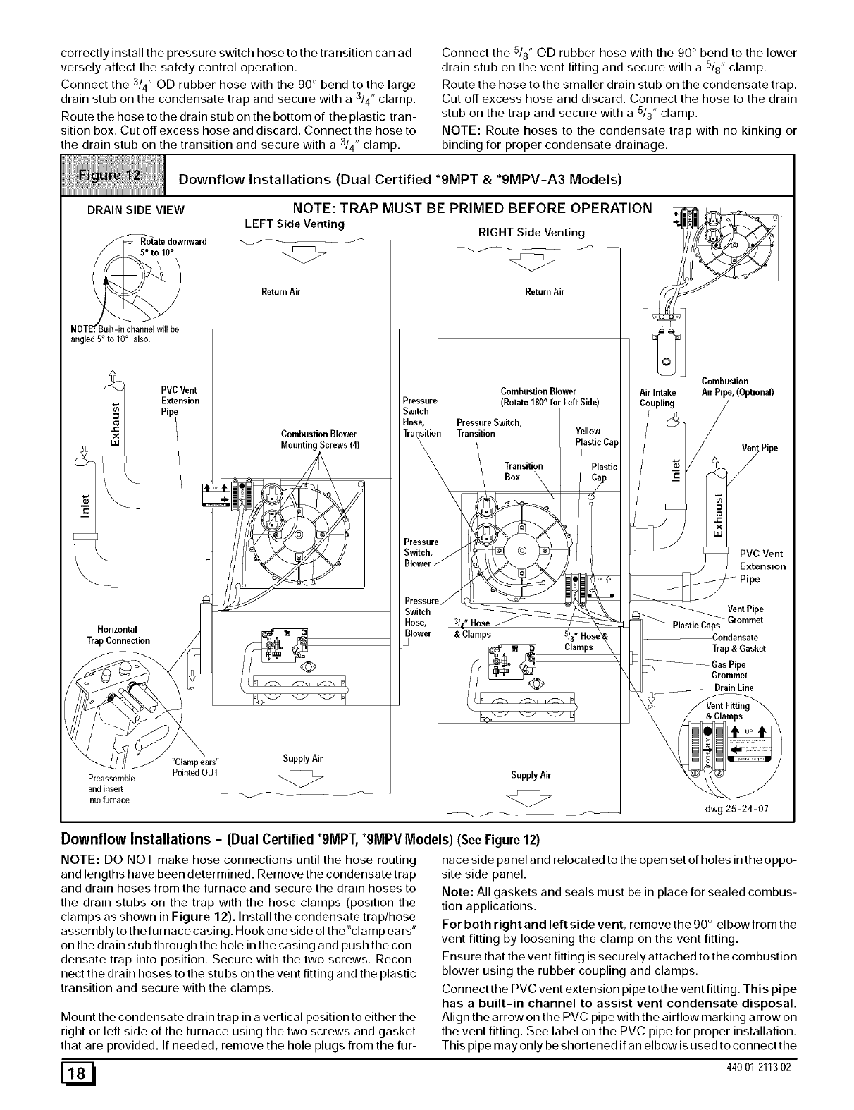
Downflow Installations (Dual Certified *9MPT & *9MPV-A3 Models)
DRAIN SIDE VIEW
/_ate downward
NOTE_. Built-in channel will be
angled 5° to 10° also.
PVCVent
Extension
Horizontal
Trap Connection
Preassemble
and insert
into furnace
LEFT Side Venting
NOTE: TRAP MUST BE PRIMED BEFORE OPERATION
RIGHT Side Venting
<Z>
ReturnAir
Combustion Blower
Mounting Screws (4)
ReturnAir
Pressure
Switch
Hose,
Transitio
Pressurq
Switch,
Blower.
Pressur,
Switch
Hose,
Blower
]
SupplyAir
<Z>
Combustion Blower
(Rotate 180° for Left Side)
Pressure Switch,
Transition Yellow
PlasticCap
Transition
Box
&Clamps
Clamps
SupplyAir
<Z>
Air Intake
Coupling
Combustion
Air Pipe, (Optional)
PlasticCaps
PVC Vent
Extension
Pipe
Vent Pipe
Grommet
Condensate
Trap & Gasket
Gas Pipe
Grommet
Brain Line
dwg 25-24-07
Downflow Installations -(Dual Certified *9MPT,*9MPV Models) (See Figure 12)
NOTE: DO NOT make hose connections until the hose routing
and lengths have been determined. Remove the condensate trap
and drain hoses from the furnace and secure the drain hoses to
the drain stubs on the trap with the hose clamps (position the
clamps as shown in Figure 12). Install the condensate trap/hose
assembly to the furnace casing. Hook one side of the"clamp ears"
on the drain stub through the hole in the casing and push the con-
densate trap into position. Secure with the two screws. Recon-
nect the drain hoses to the stubs on the vent fitting and the plastic
transition and secure with the clamps.
Mount the condensate drain trap in a vertical position to either the
right or left side of the furnace using the two screws and gasket
that are provided. If needed, remove the hole plugs from the fur-
nace side panel and relocated to the open set of holes in the oppo-
site side panel.
Note: All gaskets and seals must be in place for sealed combus-
tion applications.
For both right and left side vent, remove the 90 ° elbow from the
vent fitting by loosening the clamp on the vent fitting.
Ensure that the vent fitting is securely attached to the combustion
blower using the rubber coupling and clamps.
Connect the PVC vent extension pipe to the vent fitting. This pipe
has a built-in channel to assist vent condensate disposal.
Align the arrow on the PVC pipe with the airflow marking arrow on
the vent fitting. See label on the PVC pipe for proper installation.
This pipe may only be shortened if an elbow is used to connect the
[_ 440 01 211302
PVCventextensiontubetofield-installedventpipe.Securelyat-
tachthePVCventextensionpipetotheventfittingwiththeclamp.
Thisconfigurationallowsleftsideventingfromthefurnace.Ifright
sideventingisrequired,thecombustionblowermustberelocated
ontheplastictransitionbox.Loosenthefour(4)screwsthatse-
curetheblowertothetransitionapproximately 1/2". Rotate the
blower 180 ° and secure with the four(4) screws. Note that some
combustion blowers have plastic spacers on the mounting legs of
the blower located at the 6 and 12 o'clock positions (blower snout
to the left or right) that are required for proper fit up of the blower to
the transition. Use caution to not over tighten the screws to pre-
Vent Stripping Out Of The Plastic Mounting Holes.
Note: The vent fitting MUST be installed with the airflow marking
arrow pointed toward the vent pipe, with the drain stub at a 5 ° to
10 ° downward slope.
Plug the upper drain stub on the vent fitting with the yellow plastic
cap.
Connect the PVC vent extension pipe to the vent fitting. This pipe
has a built-in channel to assist vent condensate disposal.
Align the arrow on the PVC pipe with the airflow marking arrow on
the vent fitting. See label on the PVC pipe for proper installation.
This pipe may only be shortened if an elbow is used to connect the
PVC vent extension tube to field-installed vent pipe. Securely at-
tach the PVC vent extension pipe to the vent fitting with the clamp.
Remove the pressure switch hose from the upper stub on the
plastic transition box.
Relocate the plastic caps on the stubs of the plastic transition box
from the lower stubs to the upper stubs and secure tightly with the
clamps.
Route the pressure switch hose to the lower stub on the plastic
transition box. Cut off excess hose and discard. Connect the pres-
sure switch hose to the lower stub on the plastic transition box.
NOTE: Failure to correctly install the pressure switch hose to the
transition box can adversely affect the safety control operation.
Connect the 3/4" OD rubber hose with the 90 ° bend to the drain
stub on the bottom of the plastic transition box and secure with a
3/4" clamp.
Route the hose to the large drain stub on the condensate trap. Cut
off excess hose and discard. Connect the hose to the drain stub
on the transition and secure with a 3/4" clamp.
Connect the 5/8" OD rubber hose with the 90 ° bend to the lower
drain stub on the vent fitting and secure with a 5/8" clamp.
Route the hose to the smaller stub on the condensate trap. Cut off
excess hose and discard. Connect the hose to the drain stub on
the trap and secure with a 5/8" clamp.
For left side or right side mounted condensate trap, the pres-
sure tap on the condensate trap MUST be connected to the un-
used pressure tap located on the top of the plastic transition box.
Remove the plastic caps from the pressure taps on the conden-
sate trap and the plastic transition and connect the 5/16" OD rub-
ber hose. (See Figure 12) Route the pressure switch hose to the
lower stub on the plastic transition box. Cut off excess hoses and
discard.
Note: Route hoses to the condensate trap with no kinking or bind-
ing for proper condensate drainage.
Connecting Vent and Combustion Air Piping
CARBON MONOXIDE POISONING HAZARD.
Failure to properly seal vent piping can result in death,
personal injury and/or property damage.
Cement or mechanically seal all joints, fittings, etc. to
prevent leakage of flue gases.
Refer to the Figure 8 through Figure 12 that corresponds to the
installation position of the furnace for the application.
Preassemble the vent and combustion air piping from the furnace
to the vent termination. Do not cement the pipe joints until the pipe
preassembly process is complete.
Combustion Air Pipe Connection (Dual Certified or
Direct Vent)
Install the air intake coupling and gasket to the furnace with the
four(4) screws.
Note: The air intake coupling and gasket can be installed to the
top panel to the alternate air intake locations on either the left or
right side panels of the furnace.
For downflowinstallation, the air intake coupling and gasket must
be installed to the alternate air intake location on either the left or
right side panels. Remove the 3" hole plug from the side panel and
relocate to the air intake hole in the top panel. Use four screws to
seal the four(4) mounting holes in the top panel next to the hole
plug. Drill four(4) 7/64" diameter holes in the casing using the air
intake coupling as the template.
The air intake coupling is sized for 2" PVC pipe.
Install the combustion air pipe to the air intake coupling using RTV
sealant to provide for future serviceability.
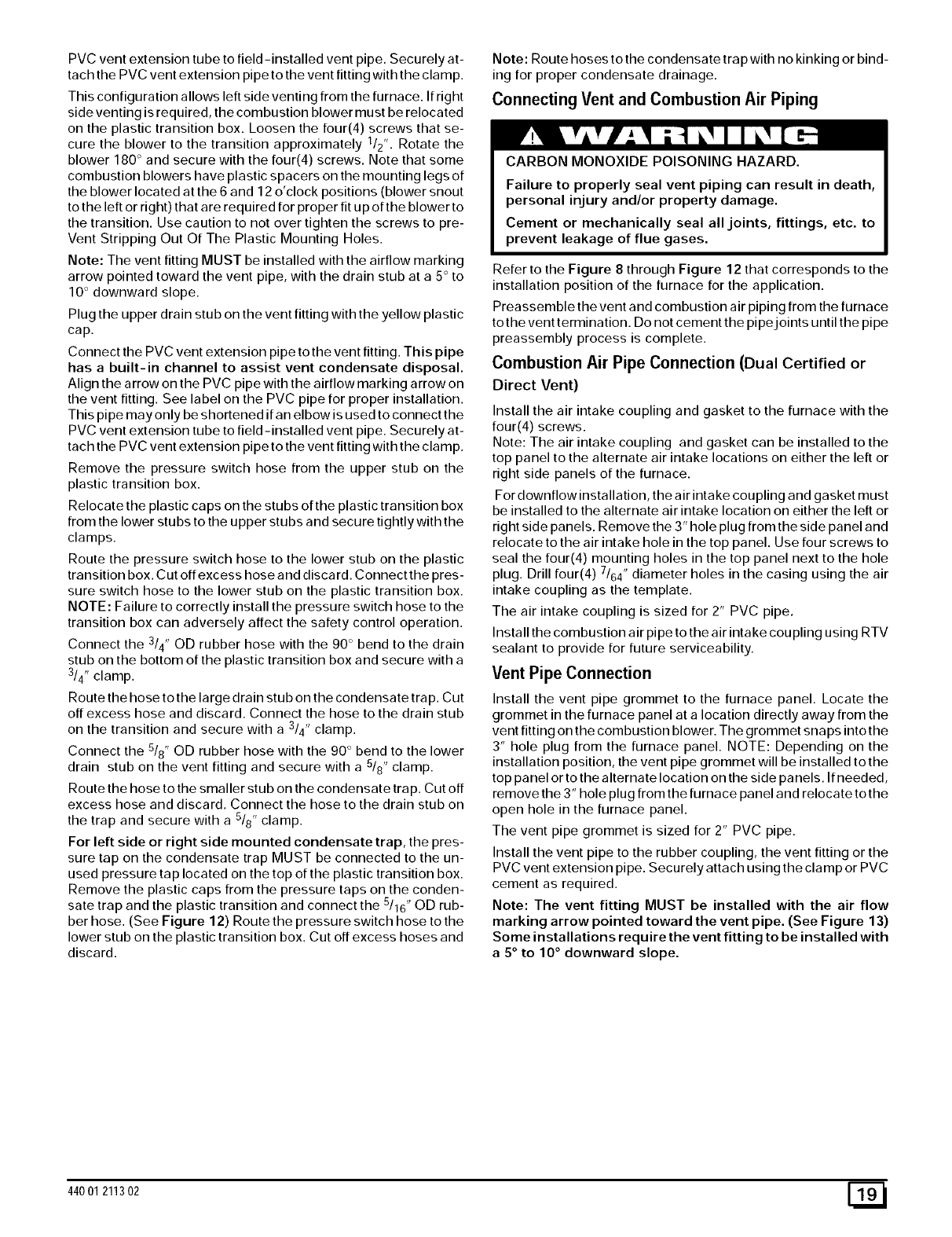
Vent Pipe Connection
Install the vent pipe grommet to the furnace panel. Locate the
grommet in the furnace panel at a location directly away from the
vent fitting on the combustion blower. The grommet snaps into the
3" hole plug from the furnace panel. NOTE: Depending on the
installation position, the vent pipe grommet will be installed to the
top panel or to the alternate location on the side panels. If needed,
remove the 3" hole plug from the furnace panel and relocate to the
open hole in the furnace panel.
The vent pipe grommet is sized for 2" PVC pipe.
Install the vent pipe to the rubber coupling, the vent fitting or the
PVC vent extension pipe. Securely attach using the clamp or PVC
cement as required.
Note: The vent fitting MUST be installed with the air flow
marking arrow pointed toward the vent pipe. (See Figure 13)
Some installations require the vent fitting to be installed with
a 5 ° to 10 ° downward slope.
44001 211302 E_
Proper Sealing Procedure for
Combustion Blower
RubberCoupling J ._ VentPipe
&Clamps ____._ _ (Top Panel Exit)
tPipe _ NOTE: The 90 ° elbow is ap-
proved for use inside the furnace
O N LY. Vent Fitting
90 ° EI_._ .... L_ _ & Clamps
Vent Extension
Pip
Exit)
DRAIN SIDE VIEW
//_te downward
NOTEr. Built -in channel will
be angled 5° to 10° also. 25-24-14
Joining Pipe and Fittings
FIRE HAZARD.
Observe all cautions and warnings printed on material
containers to prevent possible death, personal injury
and/or property damage.
Provide adequate ventilation and do NOT assemble
near heat source or open flame. Do NOT smoke while
using solvent cements and avoid contact with skin or
eyes.
This furnace is approved for venting with Schedule 40 PVC,
CPVC, ABS, Cellular Core pipe fittings and SDR-26 PVC.
NOTE: All PVC, CPVC, ABS, and Cellular Core pipe fittings, sol-
vent cement, primers and procedures MUST conform to Ameri-
can National Standard Institute and American Society for Testing
and Materials (ANSI/ASTM) standards.
Pipe and Fittings- ASTM D1785, D2241, D2466, D2661,
D2665, F-891, F-628
•PVC Primer and Solvent Cement- ASTM D2564
• Procedure for Cementing Joints - Ref ASTM D2855
NOTE: In order to create a seal that allows future removal of pipe,
RTV sealant MUST be used on the inlet pipe where it joins to
the furnace. PVC, CPVC, ABS, and Cellular Core pipe and ce-
ment may be used on all other joints.
CAUTION
Do NOT use solvent cement that has become curdled, lumpy
or thickened and do NOT thin. Observe precautions printed
on containers. For applications below 32 ° F., use only low
temperature type solvent cement.
1. Cut pipe end square, remove ragged edges and burrs.
Chamfer end of pipe, then clean fitting, socket and pipe
joint of all dirt, grease, or moisture.
NOTE: Stir the solvent cement frequently while using. Use a natu-
ral bristle brush or the dauber supplied with the cement. The prop-
er brush size is one inch.
2. After checking pipe and socket for proper fit, wipe socket
and pipe with cleaner-primer. Apply a liberal coat of primer
to inside surface of socket and outside of pipe. Do NOT al-
low primer to dry before applying cement.
3. Apply a thin coat of cement evenly in the socket. Quickly
apply a heavy coat of cement to the pipe end and insert
pipe into fittings with a slight twisting movement until it bot-
toms out.
NOTE: Cement MUST be fluid while inserting pipe. If NOT, recoat
pipe.
4. Hold the pipe in the fitting for 30 seconds to prevent the ta-
pered socket from pushing the pipe out of the fitting.
5. Wipe all excess cement from the joint with a rag. Allow 15
minutes before handling. Cure time varies according to fit,
temperature and humidity.
Connecting Vent Pipes and Termination
NOTE: Combustion air intake and vent MUST terminate in the
same atmospheric pressure zone. If installation is in a cold cli-
mate (sustained temperatures below 0 ° F), increase the minimum
distance between vent pipe and air intake from 8" to 18".
CAUTION
Maintain a minimum of 36" between combustion air inlet and
clothes dryer vent. Terminate the combustion air intake as
far as possible from any air conditioner, heat pump,
swimming pool, swimming pool pumping, chlorinator or
filtration unit.
Install all couplings, nipples and elbows using proper pro-
cedures for Joining Pipe and Fittings and maintain spac-
ing between vent and combustion air piping as indicated in
Figure 14 through Figure 21.
Sidewall Termination 12" or More
Above Snow Level or Grade Level
8" *MIN, _18,Minimumfor cold climates
20'r
MON.
[_ 440 01 211302
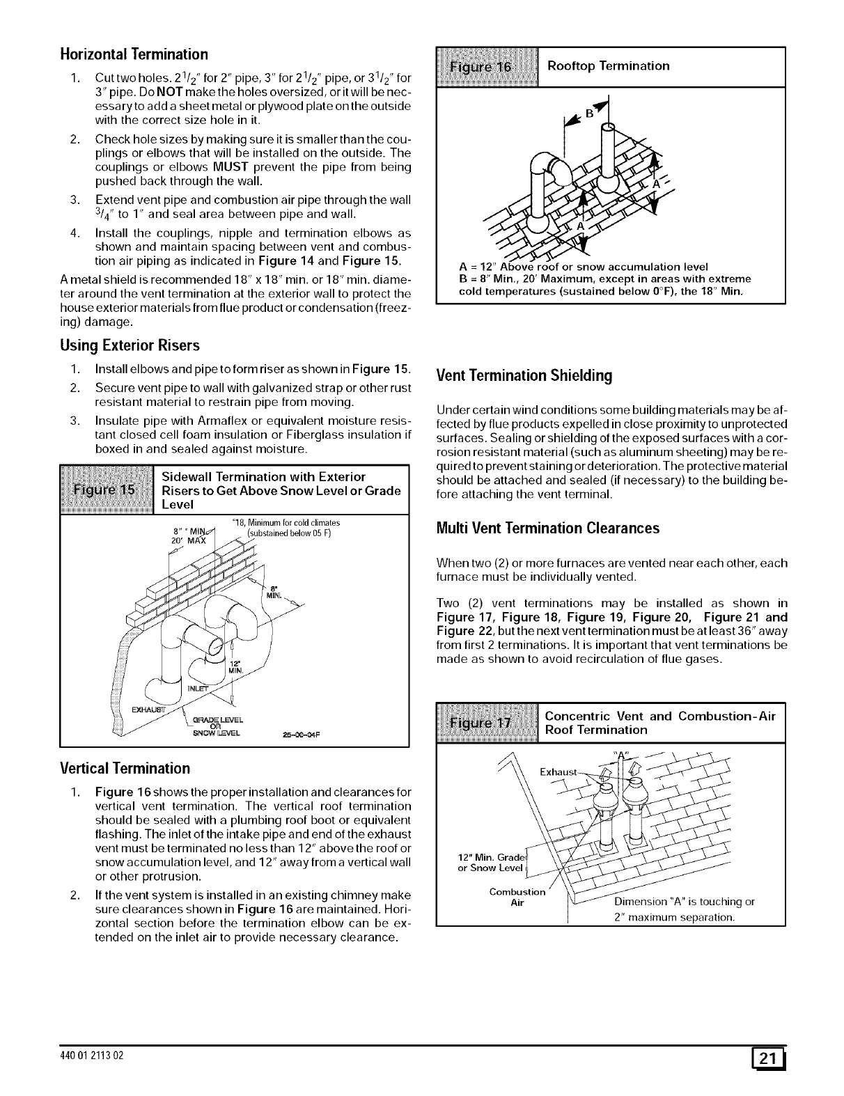
Horizontal Termination
Cut two holes. 21/2" for 2" pipe, 3" for 21/2" pipe, or 31/2" for
3" pipe. Do NOT make the holes oversized, or it will be nec-
essary to add a sheet metal or plywood plate on the outside
with the correct size hole in it.
2. Check hole sizes by making sure it is smaller than the cou-
plings or elbows that will be installed on the outside. The
couplings or elbows MUST prevent the pipe from being
pushed back through the wall.
3. Extend vent pipe and combustion air pipe through the wall
3/4" to 1" and seal area between pipe and wall.
4. Install the couplings, nipple and termination elbows as
shown and maintain spacing between vent and combus-
tion air piping as indicated in Figure 14 and Figure 15.
A metal shield is recommended 18" x 18" rain. or 18" min. diame-
ter around the vent termination at the exterior wall to protect the
house exterior materials from flue product or condensation (freez-
ing) damage.
Using ExteriorRisers
1. InstallelbowsandpipetoformriserasshowninFigure 15.
2. Secure vent pipe to wall with galvanized strap or other rust
resistant material to restrain pipe from moving.
3. Insulate pipe with Armaflex or equivalent moisture resis-
tant closed cell foam insulation or Fiberglass insulation if
boxed in and sealed against moisture.
Sidewall Termination with Exterior
Fibre t5 iRisers to Get Above Snow Level or Grade
Level
_18,Minimumforcoldclimates
substoi°e bo,ow05
f
8"
Vertical Termination
1. Figure 16 shows the proper installation and clearances for
vertical vent termination. The vertical roof termination
should be sealed with a plumbing roof boot or equivalent
flashing. The inlet of the intake pipe and end of the exhaust
vent must be terminated no less than 12" above the roof or
snow accumulation level, and 12" away from a vertical wall
or other protrusion.
2. If the vent system is installed in an existing chimney make
sure clearances shown in Figure 16 are maintained. Hori-
zontal section before the termination elbow can be ex-
tended on the inlet air to provide necessary clearance.
Rooftop Termination
A = 12" Above roof or snow accumulation level
B = 8" Min., 20' Maximum, except in areas with extreme
cold temperatures (sustained below 0°F), the 18" Min,
Vent Termination Shielding
Under certain wind conditions some building materials may be af-
fected by flue products expelled in close proximity to unprotected
surfaces. Sealing or shielding of the exposed surfaces with a cor-
rosion resistant material (such as aluminum sheeting) may be re-
quired to prevent staining or deterioration. The protective material
should be attached and sealed (if necessary) to the building be-
fore attaching the vent terminal.
Multi Vent Termination Clearances
When two (2) or more furnaces are vented near each other, each
furnace must be individually vented.
Two (2) vent terminations may be installed as shown in
Figure 17, Figure 18, Figure 19, Figure 20, Figure 21 and
Figure 22, but the next vent termination must be at least 36" away
from first 2 terminations. It is important that vent terminations be
made as shown to avoid recirculation of flue gases.
Concentric Vent and Combustion-Air
Roof Termination
12" Min.
or Snow Level
Combustion
Air Dimension "A" is touching or
2" maximum separation.
44001 211302 [_1
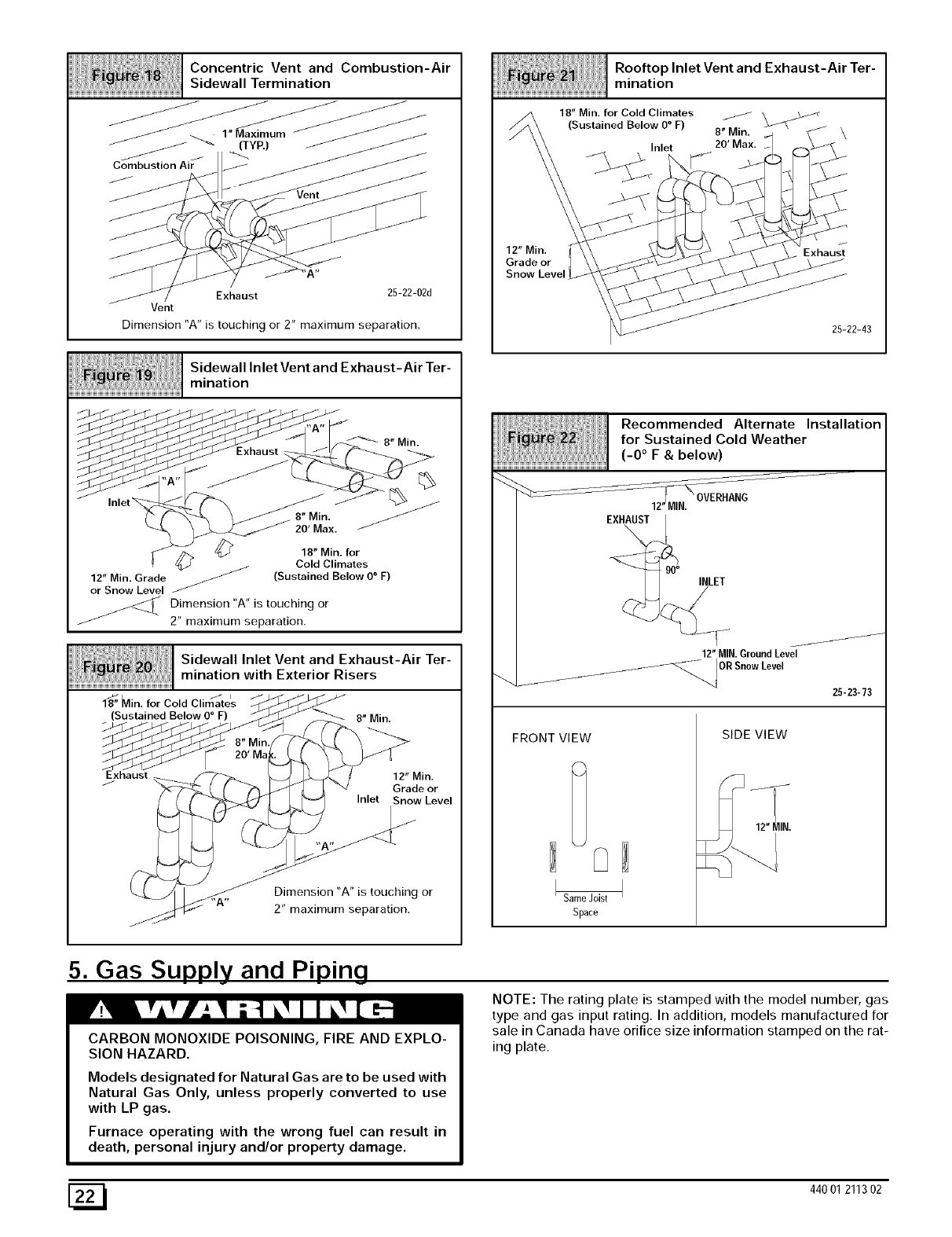
Concentric Vent and Combustion-Air
Sidewall Termination
Exhaust 25-22-02d
Vent
Dimension "A" is touching or 2" maximum separation.
12" Min.
Grade or
Snow Level
Rooftop Inlet Vent and Exhaust-Air Ter-
mination
18" Min. for Cold Climates /
(Sustained Below O° F) 8" Min. \
Inlet 20' Max.
/
Exhaust
25-22-43
Sidewall Inlet Vent and Exhaust-Air Ter-
mination
8" Min.
8" Min.
20' Max.
18" Min. for
Cold Climates
12" Min. Grade _ (Sustained Below O° F)
or Snow Level
Dimension "A" is touching or
2" maximum separation.
Sidewall Inlet Vent and Exhaust-Air Ter-
mination with Exterior Risers
/ / i
18" Min. for Cold Climates
(Sustained Below O° F) 8" Min.
Exhaust
/12" Min.
Grade or
Inlet Snow Level
Dimension "A" is touching or
2" maximum separation.
_mH_J_iHiiH_ii;!i_%ii//i!iiiii!!!iiiiiiiiiii_iiiRecommended Alternate Installation
iil i iii;:iiiiiiii
for Sustained Cold Weather
........................................................................................................................(-0 ° F & below)
12"MIN. OVERHANG
EXH_T
INLET
12"MIN.GroundLevel
/_/"_ ORSnowLevel
25-23-73
FRONT VIEW
Same Joist
Space
SIDE VIEW
12"fIN.
5. Gas Supply and Piping
CARBON MONOXIDE POISONING, FIRE AND EXPLO-
SION HAZARD.
Models designated for Natural Gas are to be used with
Natural Gas Only, unless properly converted to use
with LP gas.
Furnace operating with the wrong fuel can result in
death, personal injury and/or property damage.
NOTE: The rating plate is stamped with the model number, gas
type and gas input rating. In addition, models manufactured for
sale in Canada have orifice size information stamped on the rat-
ing plate.
1_ 440 01 211302
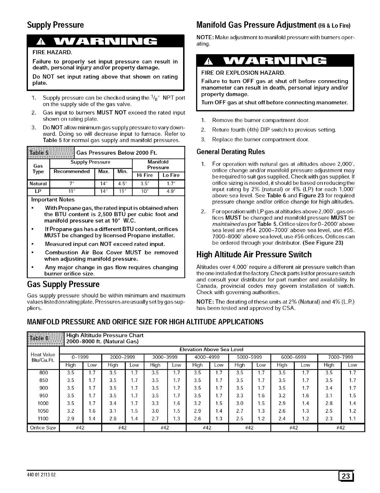
SupplyPressure
FIRE HAZARD.
Failure to properly set input pressure can result in
death, personal injury and/or property damage.
Do NOT set input rating above that shown on rating
plate.
1. Supply pressure can be checked using the 1/8" NPT port
on the supply side of the gas valve.
2. Gas input to burners MUST NOT exceed the rated input
shown on rating plate.
3. Do NOT allow minimum gas supply pressure to vary down-
ward. Doing so will decrease input to furnace. Refer to
Table 5 for normal gas supply and manifold pressures.
GaspressuresBe,ow2o00Ft
Supply Pressure Manifold
Gas Pressure
Type Recommended Max. Min. Hi Fire Lo Fire
Natural 7" 14" 4.5" 3.5" 1.7"
LP 11" 14" 11" 10" 4.9"
Important Notes
•With Propane gas, the rated input is obtained when
the BTU content is 2,500 BTU per cubic foot and
manifold pressure set at 10" W.C.
•If Propane gas has a different BTU content, orifices
MUST be changed by licensed Propane installer.
•Measured input can NOT exceed rated input.
• Combustion Air Box Cover MUST be removed
when adjusting manifold pressure.
•Any major change in gas flow requires changing
burner orifice size.
Gas Supply Pressure
Gas supply pressure should be within minimum and maximum
values listed on rating plate. Pressures a re usually set by gas su p-
pliers.
Manifold Gas Pressure Adjustment (Hi&LoFire)
NOTE: Make adjustment to manifold pressure with burners oper-
ating.
FIRE OR EXPLOSION HAZARD.
Failure to turn OFF gas at shut off before connecting
manometer can result in death, personal injury and/or
property damage.
Turn OFF gas at shut off before connecting manometer.
1. Remove the burner compartment door.
2. Reture fourth (4th) DIP switch to previous setting.
3. Replace the burner compartment door.
General Derating Rules
For operation with natural gas at altitudes above 2,000',
orifice change and/or manifold pressure adjustment may
be required to suit gas supplied. Check with gas supplier. If
orifice sizing is needed, it should be based on reducing the
input rating by 2% (natural) or 4% (LP) for each 1,000'
above sea level. See Table 6 and Figure 23 for required
pressure change and/or orifice change for high altitudes.
For operation with LP gas at altitudes above 2,000', gas ori-
fices MUST be changed and manifold pressure MUST be
maintainedas per Table 5. Orifice sizes for O-2000' a bove
sea level are #54. 2000-7000' above sea level, use #55.
7000-8000' above sea level, use #56 orifices. Orifices can
be ordered through your distributor. (See Figure 23)
High Altitude Air Pressure Switch
Altitudes over 4,000' require a different air pressure switch than
the one installed at the factory. Check parts list for pressure switch
and consult your distributor for part number and availability. In
Canada, provincial codes may govern installation of switch.
Check with governing authorities.
NOTE: The derating of these units at 2% (Natural) and 4% (L.R)
has been tested and approved by CSA.
MANIFOLD PRESSUREAND ORIFICE SIZE FOR HIGH ALTITUDE APPLICATIONS
_ie61,,iii: High Altitude Pressure Chart
2000-8000 ft. (Natural Gas)
Elevation Above Sea Level
Heat Value 2000-2999
Btu/Cu.Ft.
High Low
800
850
9OO
950
1000
1050
1100
Orifice Size
0-1999
High Low
3.5 1.7
3.5 1.7
3.5 1.7
3.5 1.7
3.5 1.7
3.2 1.6
2.9 1.4
#42
3.5 1.7
3.5 1.7
3.5 1.7
3.5 1.7
3.4 1.7
3.1 1.5
2.8 1.4
#42
3000-3999
High Low
3.5 1.7
3.5 1.7
3.5 1.7
3.5 1.7
3.3 1.6
3.0 1.5
2.7 1.3
#42
4000-4999
High Low
3.5 1.7
3.5 1.7
3.5 1.7
3.5 1.7
3.2 1.5
2.9 1.4
2.6 1.3
#42
5000-5999
High Low
3.5 1.7
3.5 1.7
3.5 1.7
3.3 1.6
3.0 1.5
2.7 1.3
2.5 1.2
#42
6000-6999
High Low
3.5 1.7
3.5 1.7
3.5 1.7
3.2 1.6
2.9 1.4
2.6 1.3
2.4 1.2
#42
7000-7999
High Low
3.5 1.7
3.5 1.7
3.4 1.7
3.1 1.5
2.8 1.4
2.5 1.2
2.3 1.1
#42
44001 211302 [_
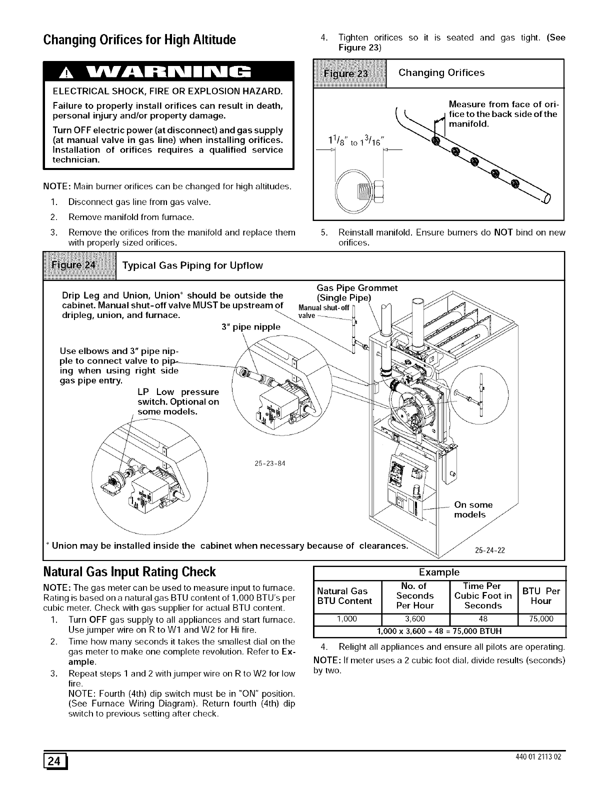
Changing Orifices for High Altitude 4Tighten orifices so it is seated and gas tight. (See
Figure 23)
ELECTRICAL SHOCK, FIRE OR EXPLOSION HAZARD.
Failure to properly install orifices can result in death,
personal injury and/or property damage.
Turn OFF electric power (at disconnect) and gas supply
(at manual valve in gas line) when installing orifices.
Installation of orifices requires a qualified service
technician.
NOTE: Main burner orifices can be changed for high altitudes.
1. Disconnect gas line from gas valve.
2. Remove manifold from furnace.
Changing Orifices
Measure from face of ori-
11/8 " to 13/16 "
3. Remove the orifices from the manifold and replace them
with properly sized orifices.
::::ii i}iii
iTyp ca,OasPipingforUpf,ow
Gas Pipe Grommet
Drip Leg and Union, Union* should be outside the (Single Pi-e) _-
cabinet. Manual shut-off valve MUST be upstream of Manualshut'off _ I-' \ :/ C _ _"_...._
dripleg, union, and furnace. _valve_._ \ / _ _ _--.._
3" pipe nipple _ _- /_'_ _ _I_
Use elbows and 3" pipe nip- ___t_ __ _
pie to connect valve to pi_--__ /\ _ _ _ k _._, _b_(.#.J¢
ing when using right sicle _ ""_"_ _-"_ ;=,_b"_
gas pipe entry. _ \ /___ _ _ '\
LP Low pressure _ _-4_k\ /_"_ J_ (_d'=_:_/'€_-_\ /
switch. Optl_na, on _ %_'_ _ \ /-_ _ _ & _ _ /
" oOe,,
.I Onsome
* Union may be installed inside the cabinet when necessary because of cle_ _ o_ -_A-_o
/_-_.-_
Natural Gas Input Rating Check
NOTE: The gas meter can be used to measure input to furnace.
Rating is based on a natural gas BTU content of 1,000 BTU's per
cubic meter. Check with gas supplier for actual BTU content.
1. Turn OFF gas supply to all appliances and start furnace.
Use jumper wire on R to Wl and W2 for Hi fire.
2. Time how many seconds it takes the smallest dial on the
gas meter to make one complete revolution. Refer to Ex-
ample.
3. Repeat steps 1 and 2 with jumper wire on R to W2 for low
fire.
NOTE: Fourth (4th) dip switch must be in "ON" position.
(See Furnace Wiring Diagram). Return fourth (4th) dip
switch to previous setting after check.
_fice to the back side of the
5. Reinstall manifold. Ensure burners do NOT bind on new
orifices.
Example
No. of Time Per
Natural Gas Seconds Cubic Foot in BTU Per
BTU Content Per Hour Seconds Hour
1,000 3,600 48 75,000
1,000 x 3,600 + 48 = 75,000 BTUH
4. Relight all appliances and ensure all pilots are operating.
NOTE: If meter uses a 2 cubic foot dial, divide results (seconds)
by two.
[_ 440 01 211302
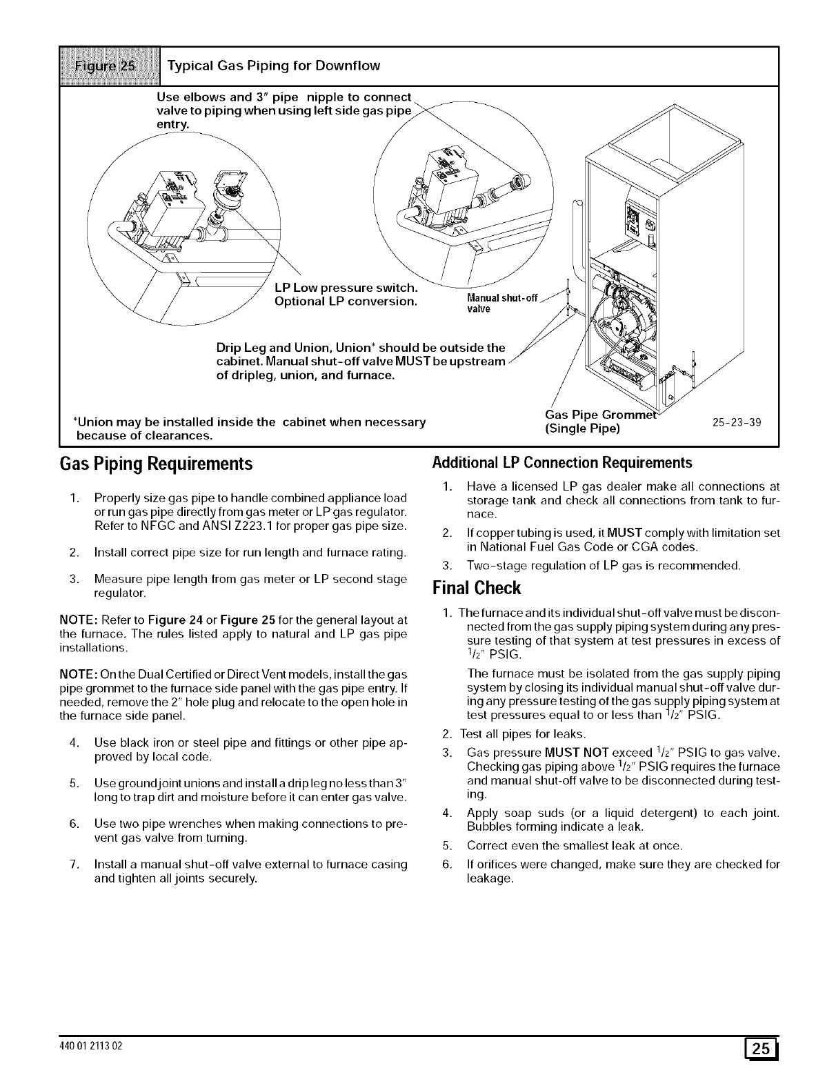
Typical Gas Piping for Downflow
Use elbows and 3" pipe nipple to connect
valve to piping when using left side gas pipe
entry.
LP Low pressure switch.
Optional LP conversion. Manualshut-off
valve
Drip Leg and Union, Union* should be outside the
cabinet. Manual shut-off valve MUST be u F
of dripleg, union, and furnace.
*Union may be installed inside the cabinet when necessary
because of clearances.
Gas Pipe
(Single Pipe) 25-23-39
Gas Piping Requirements
1. Properly size gas pipe to handle combined appliance load
or run gas pipe directly from gas meter or LP gas regulator.
Refer to NFGC and ANSI Z223.1 for proper gas pipe size.
2. Install correct pipe size for run length and furnace rating.
3. Measure pipe length from gas meter or LP second stage
regulator.
NOTE: Refer to Figure 24 or Figure 25 for the general layout at
the furnace. The rules listed apply to natural and LP gas pipe
installations.
NOTE: On the Dual Certified or Direct Vent models, install the gas
pipe grommet to the furnace side panel with the gas pipe entry. If
needed, remove the 2" hole plug and relocate to the open hole in
the furnace side panel.
4. Use black iron or steel pipe and fittings or other pipe ap-
proved by local code.
5. Use ground joint unions and install a drip leg no less than 3"
long to trap dirt and moisture before it can enter gas valve.
6. Use two pipe wrenches when making connections to pre-
vent gas valve from turning.
7. Install a manual shut-off valve external to furnace casing
and tighten all joints securely.
Additional LP Connection Requirements
1. Have a licensed LP gas dealer make all connections at
storage tank and check all connections from tank to fur-
nace.
2. If copper tubing is used, it MUST comply with limitation set
in National Fuel Gas Code or CGA codes.
3. Two-stage regulation of LP gas is recommended.
Final Check
1. The furnace and its individual shut-off valve must be discon-
nected from the gas supply piping system during any pres-
sure testing of that system at test pressures in excess of
112" PSIG.
The furnace must be isolated from the gas supply piping
system by closing its individual manual shut-off valve dur-
ing any pressure testing of the gas supply piping system at
test pressures equal to or less than 1/2" PSIG.
2. Test all pipes for leaks.
3. Gas pressure MUST NOT exceed 1/2" PSIG to gas valve.
Checking gas piping above 1/2" PSIG requires the furnace
and manual shut-off valve to be disconnected during test-
ing.
4. Apply soap suds (or a liquid detergent) to each joint.
Bubbles forming indicate a leak.
5. Correct even the smallest leak at once.
6. If orifices were changed, make sure they are checked for
leakage.
44001 211302 [_
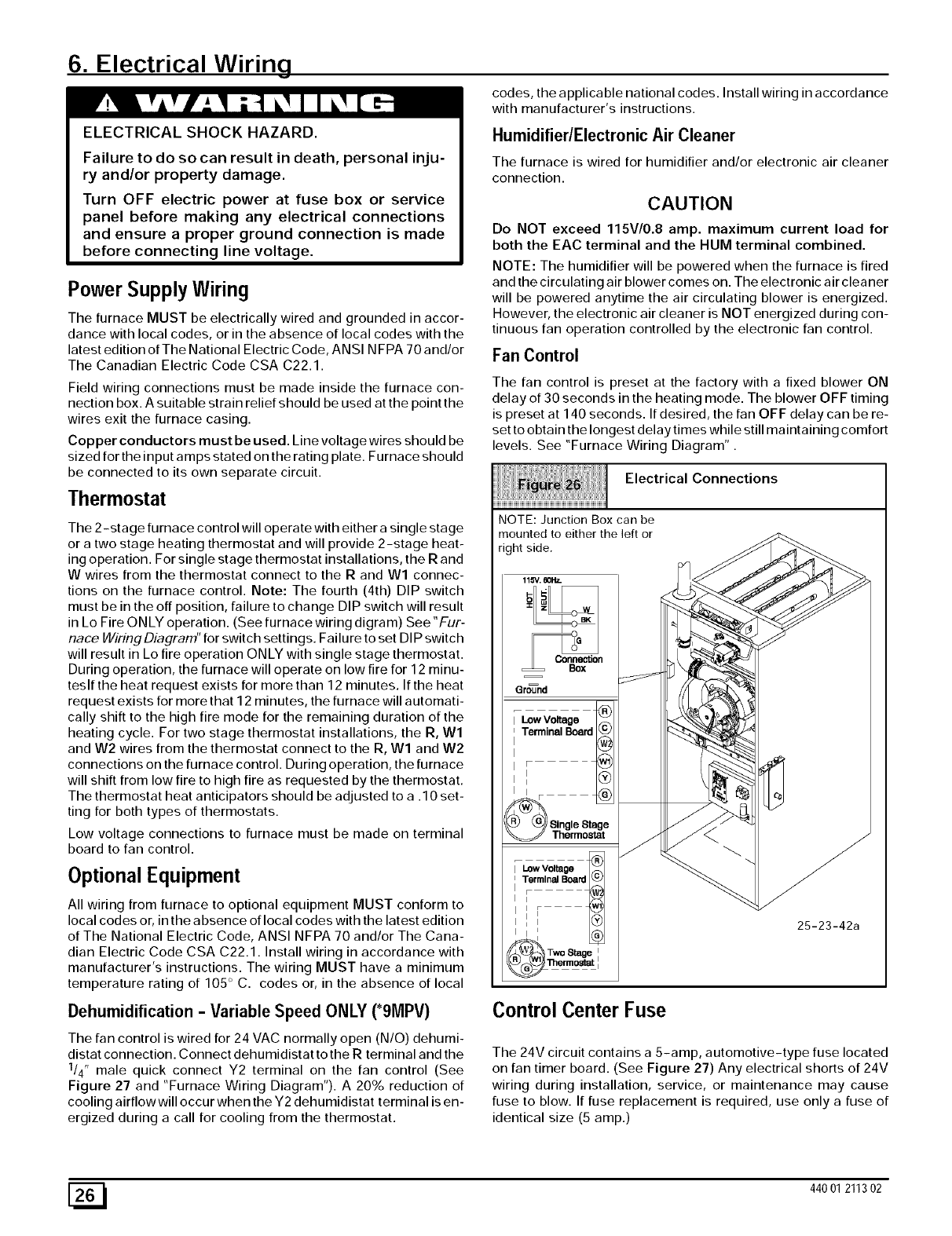
6. Electrical Wiring
ELECTRICALSHOCK HAZARD.
Failure to do so can result in death, personal inju-
ry and/or property damage.
Turn OFF electric power at fuse box or service
panel before making any electrical connections
and ensure a proper ground connection is made
before connecting line voltage.
Power Supply Wiring
The furnace MUST be electrically wired and grounded in accor-
dance with local codes, or in the absence of local codes with the
latest edition of The National Electric Code, ANSI NFPA 70 and/or
The Canadian Electric Code CSA C22.1.
Field wiring connections must be made inside the furnace con-
nection box. A suita ble strain relief should be used at the point the
wires exit the furnace casing.
Copper conductors must be used. Line voltage wires should be
sized for the input araps stated on the rating plate. Furnace should
be connected to its own separate circuit.
Thermostat
The 2-stage furnace control will operate with either a single stage
or a two stage heating thermostat and will provide 2-stage heat-
ing operation. For single stage thermostat installations, the R and
W wires from the thermostat connect to the R and Wl connec-
tions on the furnace control. Note: The fourth (4th) DIP switch
must be in the off position, failure to change DIP switch will result
in Lo Fire ONLY operation. (See furnace wiring digram) See"Fur-
nace Wiring Diagram" for switch settings. Failure to set DIP switch
will result in Lo fire operation ONLY with single stage thermostat.
During operation, the furnace will operate on low fire for 12 minu-
teslf the heat request exists for more than 12 minutes. If the heat
request exists for more that 12 minutes, the furnace will automati-
cally shift to the high fire mode for the remaining duration of the
heating cycle. For two stage thermostat installations, the R, Wl
and W2 wires from the thermostat connect to the R, Wl and W2
connections on the furnace control. During operation, the furnace
will shift from low fire to high fire as requested by the thermostat.
The thermostat heat anticipators should be adjusted to a .10 set-
ting for both types of thermostats.
Low voltage connections to furnace must be made on terminal
board to fan control.
Optional Equipment
All wiring from furnace to optional equipment MUST conform to
local codes or, in the absence of local codes with the latest edition
of The National Electric Code, ANSI NFPA 70 and/or The Cana-
dian Electric Code CSA C22.1. Install wiring in accordance with
manufacturer's instructions. The wiring MUST have a minimum
temperature rating of 105 ° C. codes or, in the absence of local
Dehumidification -Variable Speed ONLY (*9MPV)
The fan control is wired for 24 VAC normally open (N/O) dehumi-
distat connection. Connect dehumidistat to the R terminal and the
1/4" male quick connect Y2 terminal on the fan control (See
Figure 27 and "Furnace Wiring Diagram"). A 20% reduction of
cooling airflow will occur when the Y2 dehumidistat terminal is en-
ergized during a call for cooling from the thermostat.
codes, the applicable national codes. Install wiring in accordance
with manufacturer's instructions.
Humidifier/Electronic Air Cleaner
The furnace is wired for humidifier and/or electronic air cleaner
connection.
CAUTION
Do NOT exceed 115V/0.8 amp. maximum current load for
both the EAC terminal and the HUM terminal combined.
NOTE: The humidifier will be powered when the furnace is fired
and the circulating air blower comes on. The electronic air cleaner
will be powered anytime the air circulating blower is energized.
However, the electronic air cleaner is NOT energized during con-
tinuous fan operation controlled by the electronic fan control.
Fan Control
The fan control is preset at the factory with a fixed blower ON
delay of 30 seconds in the heating mode. The blower OFF timing
is preset at 140 seconds. If desired, the fan OFF delay can be re-
set to obtain the longest delay times while still maintaining comfort
levels. See "Furnace Wiring Diagram".
Electrical Connections
NOTE: Junction Box can be
mounted to either the left or
right side.
115_. 801"lz.
Connection
= = BOX
25-23-42a
Control Center Fuse
The 24V circuit contains a 5-amp, automotive-type fuse located
on fan timer board. (See Figure 27) Any electrical shorts of 24V
wiring during installation, service, or maintenance may cause
fuse to blow. If fuse replacement is required, use only a fuse of
identical size (5 amp.)
[_ 440 01 211302
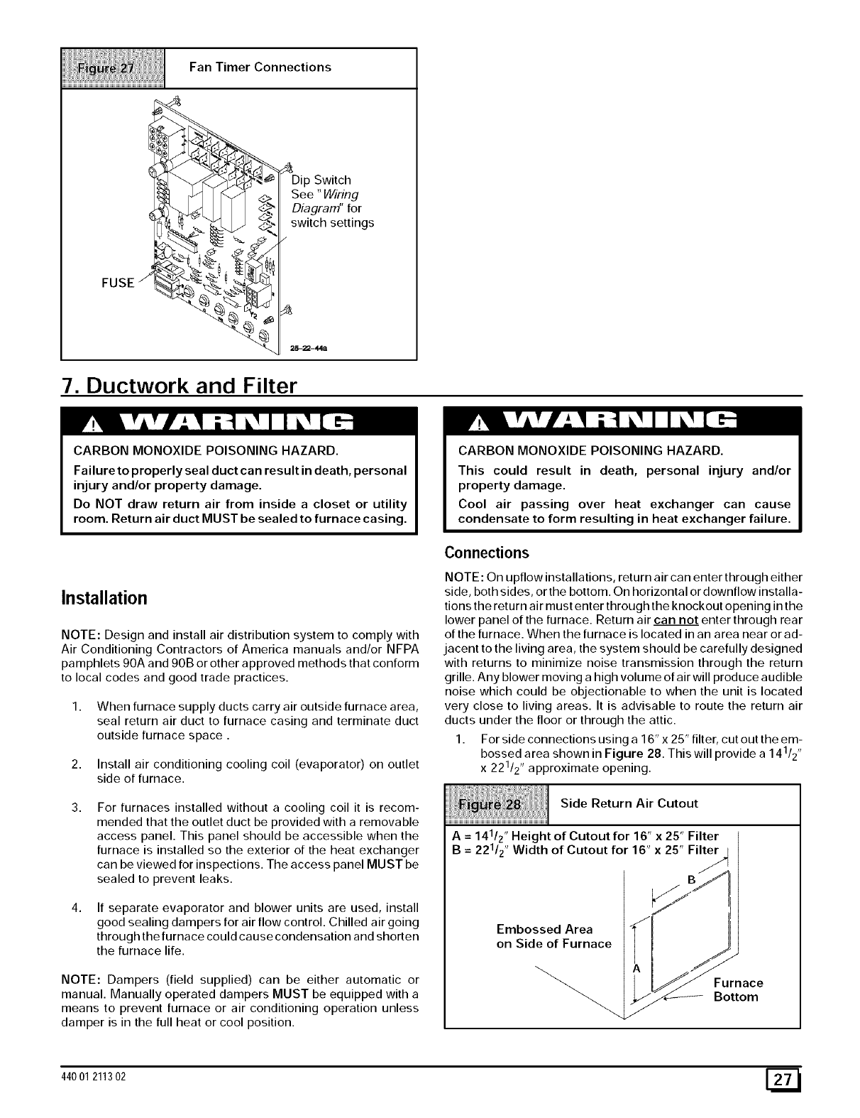
FanTimerConnections
FUSE j
Switch
See "Wiring
DiagraM' for
switch settings
7. Ductwork and Filter
CARBON MONOXIDE POISONING HAZARD.
Failure to properly seal duct can result in death, personal
injury and/or property damage.
Do NOT draw return air from inside a closet or utility
room. Return air duct MUST be sealed to furnace casing.
Installation
NOTE: Design and install air distribution system to comply with
Air Conditioning Contractors of America manuals and/or NFPA
pamphlets 90A and 90B or other approved methods that conform
to local codes and good trade practices.
1. When furnace supply ducts carry air outside furnace area,
seal return air duct to furnace casing and terminate duct
outside furnace space.
2. Install air conditioning cooling coil (evaporator) on outlet
side of furnace.
For furnaces installed without a cooling coil it is recom-
mended that the outlet duct be provided with a removable
access panel. This panel should be accessible when the
furnace is installed so the exterior of the heat exchanger
can be viewed for inspections. The access panel MUST be
sealed to prevent leaks.
If separate evaporator and blower units are used, install
good sealing dampers for air flow control. Chilled air going
through the furnace could cause condensation and shorten
the furnace life.
NOTE: Dampers (field supplied) can be either automatic or
manual. Manually operated dampers MUST be equipped with a
means to prevent furnace or air conditioning operation unless
damper is in the full heat or cool position.
CARBON MONOXIDE POISONING HAZARD.
This could result in death, personal injury and/or
property damage.
Cool air passing over heat exchanger can cause
condensate to form resulting in heat exchanger failure.
Connections
NOTE: On upflow installations, return air can enter through either
side, both sides, or the bottom. On horizontal or downflow installa-
tions the return air must enter through the knockout opening in the
lower panel of the furnace. Return air can not enter through rear
of the furnace. When the furnace is located in an area near or ad-
jacent to the living area, the system should be carefully designed
with returns to minimize noise transmission through the return
grille. Any blower moving a high volume of air will produce audible
noise which could be objectionable to when the unit is located
very close to living areas. It is advisable to route the return air
ducts under the floor or through the attic.
1. Forsideconnectionsusinga16"x25"filter, cutouttheem-
bossed area shown in Figure 28. This will provide a 141/2 ',
x 221/2 ', approximate opening.
Side Return Air Cutout
A = 141/2" Height of Cutout for 16" x 25" Filter
B = 221/z " Width of Cutout for 16" x 25" Filter
Embossed Area
on Side of Furnace
Furnace
Bottom
44001 211302 [_
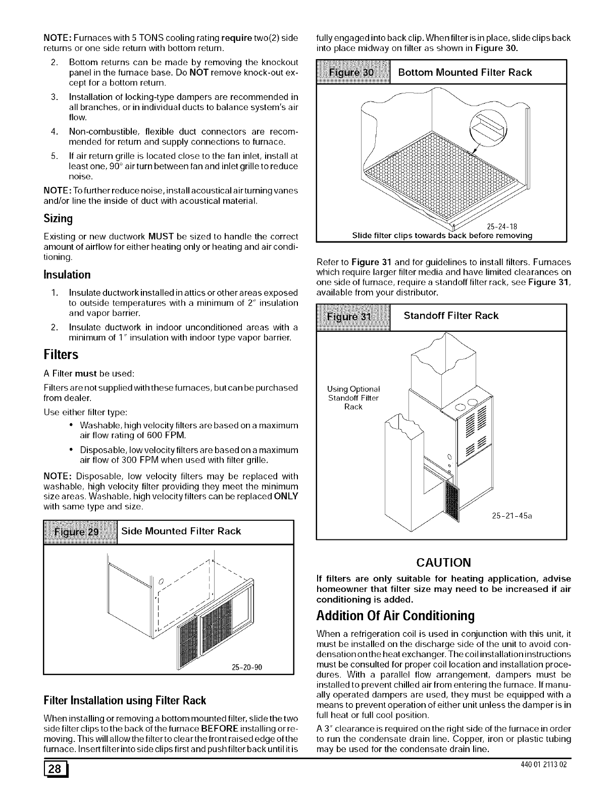
NOTE: Furnaces with 5 TONS cooling rating require two(2) side
returns or one side return with bottom return.
2. Bottom returns can be made by removing the knockout
panel in the furnace base. Do NOT remove knock-out ex-
cept for a bottom return.
3. Installation of locking-type dampers are recommended in
all branches, or in individual ducts to balance system's air
flow.
4. Non-combustible, flexible duct connectors are recom-
mended for return and supply connections to furnace.
5. If air return grille is located close to the fan inlet, install at
least one, 90 ° air turn between fan and inlet grille to reduce
noise.
NOTE: To further reduce noise, install acoustical air turning vanes
and/or line the inside of duct with acoustical material.
Sizing
Existing or new ductwork MUST be sized to handle the correct
amount of airflow for either heating only or heating and air condi-
tioning.
Insulation
1. Insulate ductworkinstalled in attics or other areas exposed
to outside temperatures with a minimum of 2" insulation
and vapor barrier.
2. Insulate ductwork in indoor unconditioned areas with a
minimum of 1" insulation with indoor type vapor barrier.
Filters
A Filter must be used:
Filters are not supplied with these furnaces, but can be purchased
from dealer.
Use either filter type:
• Washable, high velocity filters are based on a maximum
air flow rating of 600 FPM.
• Disposable, low velocity filters are based on a maximum
air flow of 300 FPM when used with filter grille.
NOTE: Disposable, low velocity filters may be replaced with
washable, high velocity filter providing they meet the minimum
size areas. Washable, high velocity filters can be replaced ONLY
with same type and size.
Side Mounted Filter Rack
25-20-90
Filter Installation using Filter Rack
When installing or removing a bottom mounted filter, slide the two
side filter clips to the back of the furnace BE FORE installing or re-
moving. This will allow the filter to clear the front raised edge of the
furnace. Insert filter into side clips first and push filter back until it is
fully engaged into back clip. When filter is in place, slide clips back
into place midway on filter as shown in Figure 30.
Bottom Mounted Filter Rack
25-24-18
Slide filter clips towards back before removing
Refer to Figure 31 and for guidelines to install filters. Furnaces
which require larger filter media and have limited clearances on
one side of furnace, require a standoff filter rack, see Figure 31,
available from your distributor.
Standoff Filter Rack
2 -21-4 a
iiHHii i i iiiiiiiiiiiiii
iiiiiiiiiiiiiiiiiiiiiiiiiiiiiiiiiiiiiiiiiiiiiiiiiiiiiiiiiiiiiiiiiiiiiiiiiiiiiiiiiiiiiiiiiiiiiiiiiiiiiiiiiiiiiiiiiiiiiiii
CAUTION
Using Optional
Standoff Filter
Rack
If filters are only suitable for heating application, advise
homeowner that filter size may need to be increased if air
conditioning is added.
Addition Of Air Conditioning
When a refrigeration coil is used in conjunction with this unit, it
must be installed on the discharge side of the unit to avoid con-
densation on the heat exchanger. The coil insta Ilation instructions
must be consulted for proper coil location and installation proce-
dures. With a parallel flow arrangement, dampers must be
installed to prevent chilled air from entering the furnace. If manu-
ally operated dampers are used, they must be equipped with a
means to prevent operation of either unit unless the damper is in
full heat or full cool position.
A 3" clearance is required on the right side of the furnace in order
to run the condensate drain line. Copper, iron or plastic tubing
may be used for the condensate drain line.
[_ 440 01 211302
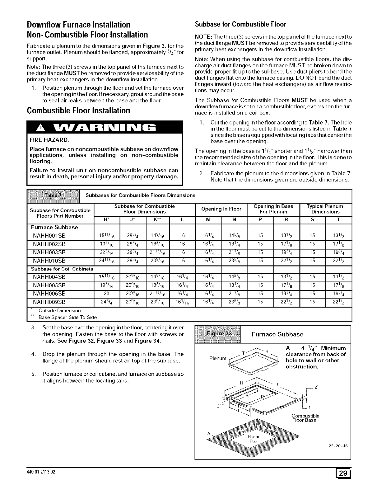
Downflow Furnace Installation
Non- Combustible Floor Installation
Fabricate a plenum to the dimensions given in Figure 3, for the
furnace outlet. Plenum should be flanged, approximately 3/4" for
support.
Note: The three(3) screws in the top panel of the furnace next to
the duct flange MUST be removed to provide serviceability of the
primary heat exchangers in the downflow installation
1. Position plenum through the floor and set the furnace over
the opening in the floor. If necessary, grout around the base
to seal air leaks between the base and the floor.
Combustible Floor Installation
FIRE HAZARD.
Place furnace on noncombustible subbase on downflow
applications, unless installing on non-combustible
flooring.
Failure to install unit on noncombustible subbase can
result in death, personal injury and/or property damage.
Subbase for Combustible Floor
NOTE: The three(3) screws in the top panel of the furnace next to
the duct flange MUST be removed to provide serviceability of the
primary heat exchangers in the downflow installation
Note: When using the subbase for combustible floors, the dis-
charge air duct flanges on the furnace MUST be broken down to
provide proper fit up to the subbase. Use duct pliers to bend the
duct flanges flat onto the furnace casing. DO NOT bend the duct
flanges inward (toward the heat exchangers) as air flow restric-
tions may occur.
The Subbase for Combustible Floors MUST be used when a
downflow furnace is set on a combustible floor, even when the fur-
nace is installed on a coil box.
1. Cut the opening in the floor according to Table 7. The hole
in the floor must be cut to the dimensions listed in Table 7
since the base is equipped with locating tabs that center the
base over the opening.
The opening in the base is 11/4 ', shorter and 11/8 ', narrower than
the recommended size of the opening in the floor. This is done to
maintain clearance between the floor and the plenum.
2. Fabricate the plenum to the dimensions given in Table 7.
Note that the dimensions given are outside dimensions.
Subbase for Combustible
Floors Part Number
Furnace Subbase
NAHHOOISB
NAHHOO2SB
NAHHOO3SB
NAHHOIOSB
Subbase for Coil Cabinets
NAHHOO4SB
NAHHOO5SB
NAHHOO6SB
NAHHOO9SB
Outside Dimension
Base Spacer Side To Side
3.
Subbases for Combustible Floors Dimensions
Opening In Floor
M N
16114 145/8
16114 18114
161/4 21 t/8
161/4 236/8
161/4 145/8
161/4 181/4
161/4 21 _/8
161/4 236/8
Subbase for Combustible
Floor Dimensions
H*
1511/16
195/16
225/16
2411/16
1511/16
195/16
23
243/4
J_ K**
28314 149/16 16
28J/4 183/16 16
28314 2113116 16
28314 239116 16
209/16 149/16 161/4
20u/16 18:_/16 161/4
209/16 2113/16 161/4
209/16 239/16 161/16
Set the base over the opening in the floor, centering it over
the opening. Fasten the base to the floor with screws or
nails. See Figure 32, Figure 33 and Figure 34.
Drop the plenum through the opening in the base. The
flange of the plenum should rest on top of the subbase.
Position furnace or coil cabinet and furnace on subbase so
it aligns between the locating tabs.
Plenum
Opening In Base
For Plenum
P R
15 13112
15 17118
15 193/4
15 22112
15 13112
15 17118
15 193/4
15 22112
Furnace Subbase
s
Typical Plenum
Dimensions
ST
15 131/2
15 17118
15 193/4
15 22112
15 131/2
15 171/8
15 193/4
15 221/2
A = 4 1/4" Minimum
clearance from back of
hole to wall or other
obstruction.
1"
Combustible
Floor Base
25-20-46
44001 211302 [_
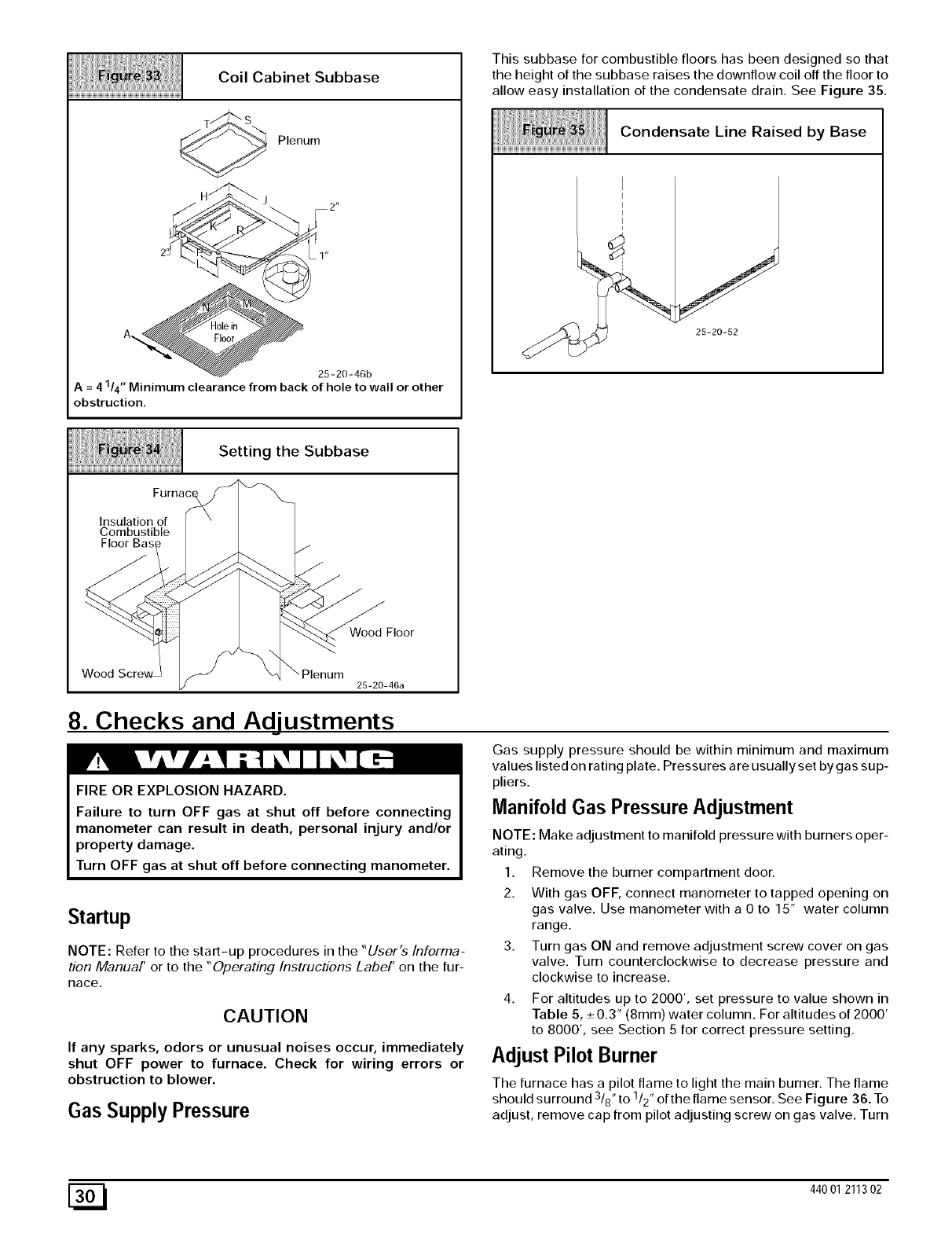
Coil Cabinet Subbase
Plenum
25-20-46b
=41/4" Minimum clearance from back of hole to wall or other
A
obstruction,
This subbase for combustible floors has been designed so that
the height of the subbase raises the downflow coil off the floor to
allow easy installation of the condensate drain. See Figure 35.
Condensate Line Raised by Base
25-20-52
Setting the Subbase
HHHHHHHHHHHHHHHHHHHHHHHHHHHHHHHHHHHHHHHHHHHHHHHHHHHHHHHHHHHHHH
Furna
Insulation of
Combustible
Floor Bas_ /
Wood '- \P,ooom
_- 25-20-46a
8. Checks and Adjustments
FIRE OR EXPLOSION HAZARD.
Failure to turn OFF gas at shut off before connecting
manometer can result in death, personal injury and/or
property damage.
Gas supply pressure should be within minimum and maximum
values listed on rating plate. Pressures are usually set by gas sup-
pliers.
Manifold Gas Pressure Adjustment
NOTE: Make adjustment to manifold pressure with burners oper-
ating.
Turn OFF gas at shut off before connecting manometer.
Startup
NOTE: Refer to the start-up procedures in the "User's Informa-
tion Manual' or to the "Operating Instructions Label' on the fur-
Race.
CAUTION
If any sparks, odors or unusual noises occur, immediately
shut OFF power to furnace. Check for wiring errors or
obstruction to blower.
Gas Supply Pressure
1. Remove the burner compartment door.
2. With gas OFF, connect manometer to tapped opening on
gas valve. Use manometer with a 0 to 15" water column
range.
3. Turn gas ON and remove adjustment screw cover on gas
valve. Turn counterclockwise to decrease pressure and
clockwise to increase.
4. For altitudes up to 2000', set pressure to value shown in
Table 5, ÷ 0.3" (Smm) water column. For altitudes of 2000'
to 8000', see Section 5 for correct pressure setting.
Adjust Pilot Burner
The furnace has a pilot flame to light the main burner. The flame
should surround 318"to 1/2" of the flame sensor. See Figure 36. To
adjust, remove cap from pilot adjusting screw on gas valve. Turn
[_ 440 01 211302
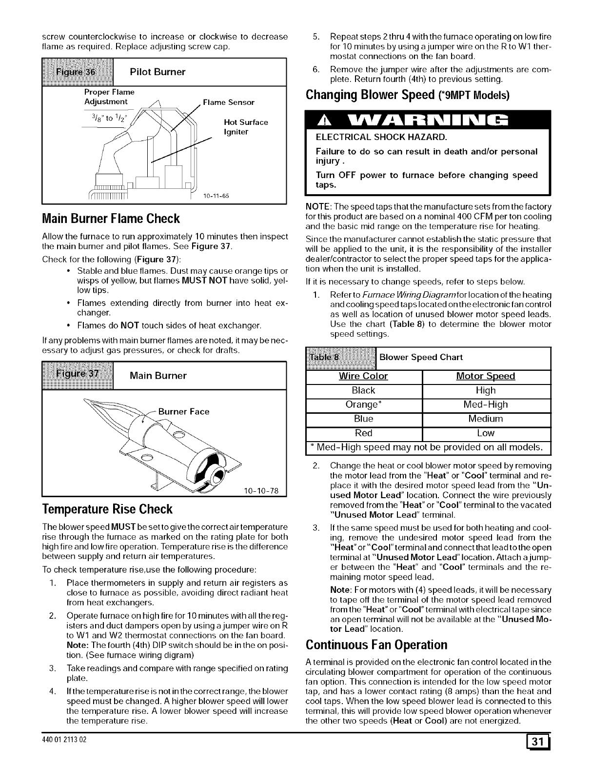
screwcounterclockwiseto increase or clockwise to decrease
flame as required. Replace adjusting screw cap.
Pilot Burner
Proper Flame
Adjustment _/Flame Sensor
318"t°112"/_ Hot Surface
/Igniter
10-11-65
Main Burner FlameCheck
Allow the furnace to run approximately 10 minutes then inspect
the main burner and pilot flames. See Figure 37.
Check for the following (Figure 37):
•Stable and blue flames. Dust may cause orange tips or
wisps of yellow, but flames MUST NOT have solid, yel-
low tips.
• Flames extending directly from burner into heat ex-
changer.
• Flames do NOT touch sides of heat exchanger.
If any problems with main burner flames are noted, it may be nec-
essary to adjust gas pressures, or check for drafts.
Main Burner
10-10-78
Temperature Rise Check
The blower speed MUST be set to give the correct air temperature
rise through the furnace as marked on the rating plate for both
high fire and low fire operation. Temperature rise is the difference
between supply and return air temperatures.
To check temperature rise,use the following procedure:
1. Place thermometers in supply and return air registers as
close to furnace as possible, avoiding direct radiant heat
from heat exchangers.
2. Operate furnace on high fire for 10 minutes with all the reg-
isters and duct dampers open by using a jumper wire on R
to Wl and W2 thermostat connections on the fan board.
Note: The fourth (4th) DIP switch should be in the on posi-
tion. (See furnace wiring digram)
3. Take readings and compare with range specified on rating
plate.
4. If the temperature rise is not in the correct range, the blower
speed must be changed. A higher blower speed will lower
the temperature rise. A lower blower speed will increase
the temperature rise.
5. Repeat steps 2 thru 4 with the furnace operating on low fire
for 10 minutes by using a jumper wire on the R to W1 ther-
mostat connections on the fan board.
6. Remove the jumper wire after the adjustments are com-
plete. Return fourth (4th) to previous setting.
Changing Blower Speed (*9MPTModels)
ELECTRICAL SHOCK HAZARD.
Failure to do so can result in death and/or personal
injury.
Turn OFF power to furnace before changing speed
taps.
NOTE: The speed taps that the manufacture sets from the factory
for this product are based on a nominal 400 CFM per ton cooling
and the basic mid range on the temperature rise for heating.
Since the manufacturer cannot establish the static pressure that
will be applied to the unit, it is the responsibility of the installer
dealer/contractor to select the proper speed taps for the applica-
tion when the unit is installed.
If it is necessary to change speeds, refer to steps below.
1. Refer to Furnace WMngDiagramfor location of the heating
and cooling speed taps located on the electronic fan control
as well as location of unused blower motor speed leads.
Use the chart (Table 8) to determine the blower motor
speed settings.
Blower Speed Chart
Wire Color
Black
Orange*
Blue
Red
Motor Speed
High
Med-High
Medium
Low
* Med-High speed may not be provided on all models.
Change the heat or cool blower motor speed by removing
the motor lead from the "Heat" or "coor' terminal and re-
place it with the desired motor speed lead from the "Un-
used Motor Lead" location. Connect the wire previously
removed from the "Heat" or "coor' terminal to the vacated
"Unused Motor Lead" terminal.
If the same speed must be used for both heating and cool-
ing, remove the undesired motor speed lead from the
"Heat" or"Coor' terminal and connect that lead to the open
terminal at "Unused Motor Lead" location. Attach a jump-
er between the "Heat" and "coor' terminals and the re-
maining motor speed lead.
Note: For motors with (4) speed leads, it will be necessary
to tape off the terminal of the motor speed lead removed
from the "Heat" or "coor' terminal with electrical tape since
an open terminal will not be available at the "Unused Mo-
tor Lead" location.
Continuous Fan Operation
A terminal is provided on the electronic fan control located in the
circulating blower compartment for operation of the continuous
fan option. This connection is intended for the low speed motor
tap, and has a lower contact rating (8 amps) than the heat and
cool taps. When the low speed blower lead is connected to this
terminal, this will provide low speed blower operation whenever
the other two speeds (Heat or Cool) are not energized.
44001 211302 [_
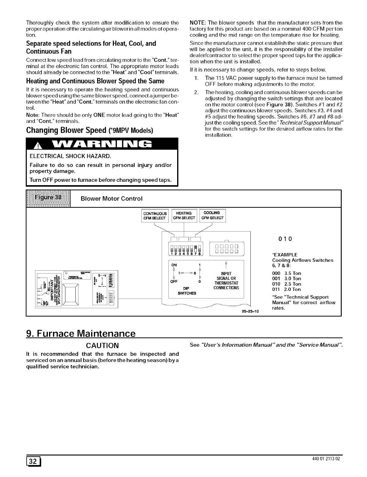
Thoroughlycheckthesystemaftermodificationtoensurethe
proper operation of the circulating air blower in all modes of opera-
tion.
Separate speed selections for Heat, Cool, and
Continuous Fan
Connect low speed lead from circulating motor to the "Cont." ter-
minal at the electronic fan control. The appropriate motor leads
should already be connected to the "Heat" and "Cool" terminals.
Heating and Continuous Blower Speed the Same
If it is necessary to operate the heating speed and continuous
blower speed using the same blower speed, connect ajumper be-
tween the "Heat" and "Cont." terminals on the electronic fan con-
trol.
Note: There should be only ONE motor lead going to the "Heat"
and "Cont." terminals.
Changing Blower Speed (*91VlpVMlodels)
NOTE: The blower speeds that the manufacturer sets from the
factory for this product are based on a nominal 400 CFM per ton
cooling and the mid range on the temperature rise for heating.
Since the manufacturer cannot establish the static pressure that
will be applied to the unit, it is the responsibility of the installer
dealer/contractor to select the proper speed taps for the applica-
tion when the unit is installed.
If it is
1.
necessary to change speeds, refer to steps below.
The 115 VAC power supply to the furnace must be turned
OFF before making adjustments to the motor.
The heating, cooling and continuous blower speeds can be
adjusted by changing the switch settings that are located
on the motor control (see Figure 38). Switches #1 and #2
adjust the continuous blower speeds. Switches #3, #4 and
#5 adjust the heating speeds. Switches #6, #7 and #8 ad-
just the cooling speed. See the" TechnicalSupportManual"
for the switch settings for the desired airflow rates for the
installation.
ELECTRICAL SHOCK HAZARD.
Failure to do so can result in personal injury and/or
property damage.
Turn OFF power to furnace before changing speed taps.
Blower Motor Control
ON 1
;1_8 ; INPUT
SIGNAL OR
OFF 0 THERMOSTAT
DIP CONNECTIONS
SWITCHES
010
*EXAMPLE
Cooling Airflows Switches
6,7&8:
000 3,5 Ton
001 3.0 Ton
010 2,5 Ton
011 2.0 Ton
*See "Technical Support
Manual" for correct airflow
rates.
25-23-10
See "User "s Information Manual" and the "Service Manual".
9. Furnace Maintenance
CAUTION
It is recommended that the furnace be inspected and
serviced on an annual basis (before the heating season) by a
qualified service technician.
[_ 440 01 211302
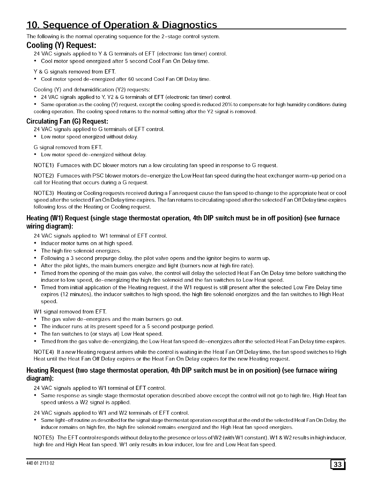
10. Sequence of Operation & Diagnostics
The following is the normal operating sequence for the 2-stage control system.
Cooling (Y) Request:
24 VAC signals applied to Y &G terminals of EFT (electronic fan timer) control.
• Cool motor speed energized after 5 second Cool Fan On Delay time.
Y & G signals removed from EFT.
• Cool motor speed de-energized after 60 second Cool Fan Off Delay time.
Cooling (Y) and dehumidification (Y2) requests:
• 24 VAC signals applied to Y, Y2 & G terminals of EFT (electronic fan timer) control.
• Same operation as the cooling (Y) request, except the cooling speed is reduced 20% to compensate for high humidity conditions during
cooling operation. The cooling speed returns to the normal setting after the Y2 signal is removed.
Circulating Fan (G) Request:
24 VAC signals applied to G terminals of EFT control.
• Low motor speed energized without delay.
G signal removed from EFT.
• Low motor speed de-energized without delay.
NOTE1) Furnaces with DC blower motors run a low circulating fan speed in response to G request.
NOTE2) Furnaces with PSC blower motors de-energize the Low Heat fan speed during the heat exchanger warm-up period on a
call for Heating that occurs during a G request.
NOTE3) Heating or Cooling requests received during a Fan request cause the fan speed to change to the appropriate heat or cool
speed after the selected Fan On Delay time ex pires. The fan returns to circulating speed after the selected Fan Off Delay time expires
following loss of the Heating or Cooling request.
Heating (Wl) Request (single stage thermostat operation, 4th DIP switch must be in off position) (see furnace
wiring diagram):
24 VAC signals applied to W1 terminal of EFT control.
• Inducer motor turns on at high speed.
• The high fire solenoid energizes.
• Following a 3 second prepurge delay, the pilot valve opens and the ignitor begins to warm up.
• After the pilot lights, the main burners energize and light (burners now at high fire rate).
• Timed from the opening of the main gas valve, the control will delay the selected Heat Fan On Delay time before switching the
inducer to low speed, de-energizing the high fire solenoid and the fan switches to Low Heat speed.
• Timed from initial application of the Heating request, if the Wl request is still present after the selected Low Fire Delay time
expires (12 minutes), the inducer switches to high speed, the high fire solenoid energizes and the fan switches to High Heat
speed.
Wl signal removed from EFT.
• The gas valve de-energizes and the main burners go out.
• The inducer runs at its present speed for a 5 second postpurge period.
• The fan switches to (or stays at) Low Heat speed.
• Timed from the gas valve de-energizing, the Low Heat fan speed de-energizes after the selected Heat Fan Delay time expires.
NOTE4) If a new Heating request arrives while the control is waiting in the Heat Fan Off Delay time, the fan speed switches to High
Heat until the Heat Fan Off Delay expires or the Heat Fan On Delay expires for the new Heating request.
Heating Request (two stage thermostat operation, 4th DIP switch must be in on position) (see furnace wiring
diagram):
24 VAC signals applied to Wl terminal of EFT control.
• Same response as single stage thermostat operation described above except the control will not go to high fire, High Heat fan
speed unless a W2 signal is applied.
24 VAC signals applied to Wl and W2 terminals of EFT control.
• Same light-off routine as described for the signal stage thermostat operation except that at the end of the selected Heat Fan On Delay, the
inducer remains on high fire, the high fire solenoid remains energized and the High Heat fan speed energizes.
NOTE5) The EFT control responds without delay to the presence or loss of W2 (with Wl constant). Wl & W2 results in high inducer,
high fire and High Heat fan speed. W1 only results in low inducer, low fire and Low Heat fan speed.
44001 211302 E_
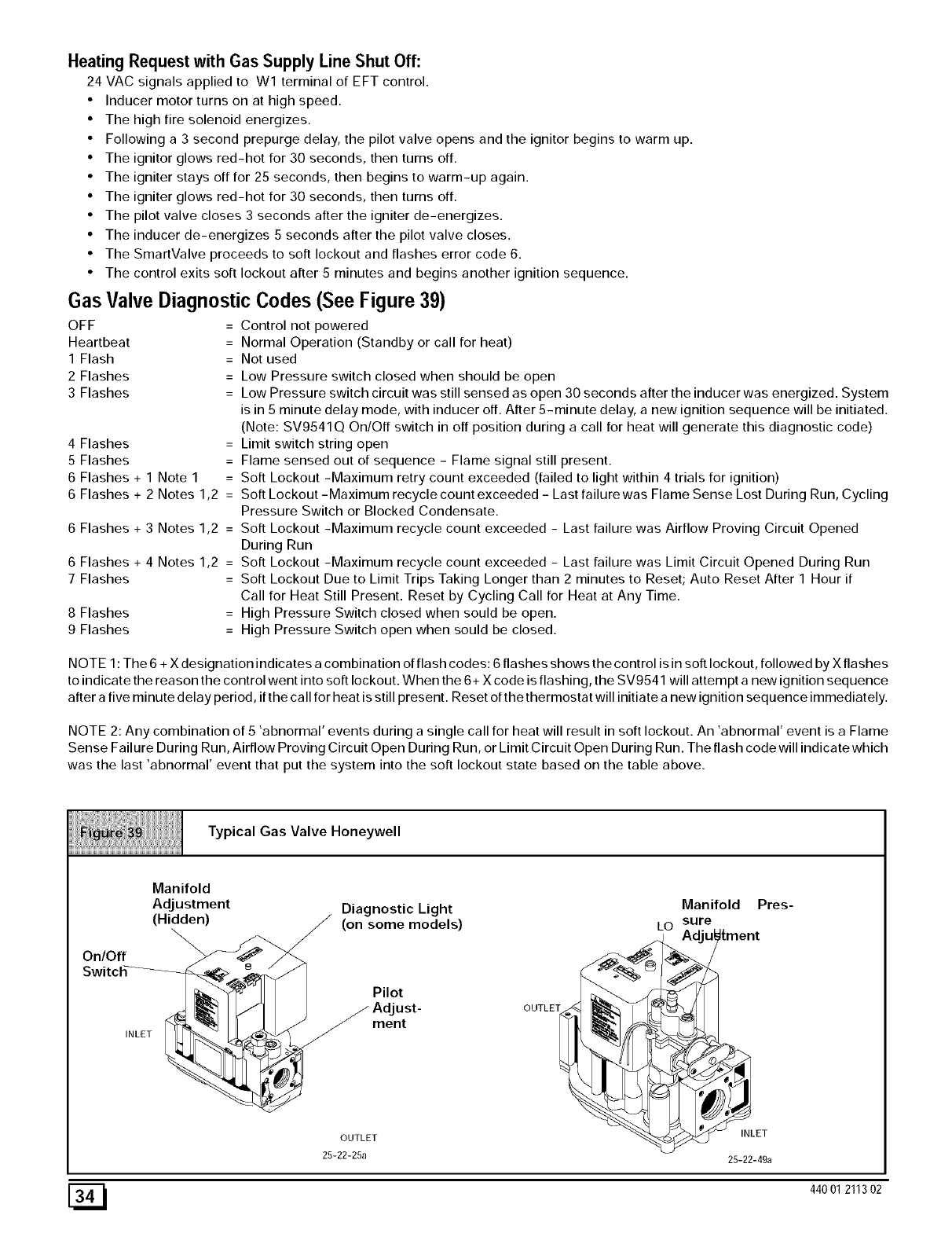
Heating Request with Gas Supply Line Shut Off:
24 VAC signals applied to Wl terminal of EFT control.
• Inducer motor turns on at high speed.
• The high fire solenoid energizes.
• Following a 3 second prepurge delay, the pilot valve opens and the ignitor begins to warm up.
• The ignitor glows red-hot for 30 seconds, then turns off.
• The igniter stays off for 25 seconds, then begins to warm-up again.
• The igniter glows red-hot for 30 seconds, then turns off.
• The pilot valve closes 3 seconds after the igniter de-energizes.
• The inducer de-energizes 5 seconds after the pilot valve closes.
• The SmartValve proceeds to soft lockout and flashes error code 6.
• The control exits soft lockout after 5 minutes and begins another ignition sequence.
Gas Valve Diagnostic Codes (See Figure 39)
OFF = Control not powered
Heartbeat = Normal Operation (Standby or call for heat)
1 Flash =
2 Flashes
3 Flashes
4 Flashes =
5 Flashes =
6 Flashes + 1 Note 1 =
6 Flashes + 2 Notes 1,2 =
6 Flashes + 3 Notes 1,2 =
6 Flashes + 4 Notes 1,2 =
7 Flashes =
8 Flashes =
9 Flashes =
Not used
Low Pressure switch closed when should be open
Low Pressure switch circuit was still sensed as open 30 seconds after the inducer was energized. System
is in 5 minute delay mode, with inducer off. After 5-minute delay, a new ignition sequence will be initiated.
(Note: SV9541 Q On/Off switch in off position during a call for heat will generate this diagnostic code)
Limit switch string open
Flame sensed out of sequence - Flame signal still present.
Soft Lockout -Maximum retry count exceeded (failed to light within 4 trials for ignition)
Soft Lockout -Maximum recycle count exceeded - Last failure was Flame Sense Lost During Run, Cycling
Pressure Switch or Blocked Condensate.
Soft Lockout -Maximum recycle count exceeded - Last failure was Airflow Proving Circuit Opened
During Run
Soft Lockout -Maximum recycle count exceeded - Last failure was Limit Circuit Opened During Run
Soft Lockout Due to Limit Trips Taking Longer than 2 minutes to Reset; Auto Reset After 1 Hour if
Call for Heat Still Present. Reset by Cycling Call for Heat at Any Time.
High Pressure Switch closed when sould be open.
High Pressure Switch open when sould be closed.
NOTE 1 : The 6 + X designation indicates a combination of flash codes: 6 flashes shows the control is in soft lockout, followed by X flashes
to indicate the reason the control went into soft lockout. When the 6+ X code is flashing, the SV9541 will attempt a new ignition sequence
after a five minute delay period, if the call for heat is still present. Reset of the thermostat will initiate a new ignition sequence immediately.
NOTE 2: Any combination of 5 'abnormal' events during a single call for heat will result in soft lockout. An 'abnormal' event is a Flame
Sense Failure During Run, Airflow Proving Circuit Open During Run, or Limit Circuit Open During Run. The flash code will indicate which
was the last 'abnormal' event that put the system into the soft lockout state based on the table above.
Typical Gas Valve Honeywell
On/Off
INLET
Manifold
AdJustment
(Hidden) Diagnostic Light Manifold
(on some models) LO sure
Pilot
ust-
ment
OUTLET
Pres-
OUTLET
25-22-25a
INLET
25-22-49a
[_ 440 01 211302
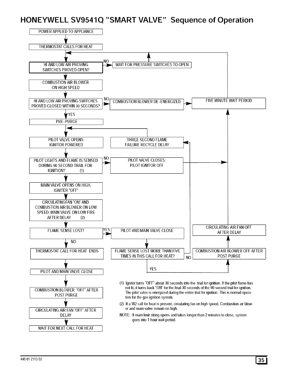
HONEYWELL SV9541Q "SMART VALVE" Sequence of Operation
I POWERAPPLIEDTOAPPLIANCE I
I THERMOSTATCALLSFORHEATI
HIANDLOWAIR PROVING _ WAITFORPRESSURESWITCHESTO OPEN I
SWITCHESPROVEDOPEN? /
V
COMBUSTIONAIR BLOWER
ONHIGHSPEED
..ANO,OWA.RpROV.NGSW.TC.ESCOM0UST.ON0,OWEROEENERG.ZEOF.VEM.NU,EWA.,PER.OOPROVEDCLOSEDWITHIN30SECONDS?
YES
PRE-PURGE
PILOTVALVEOPENS: THREESECONDFLAME L..,,
IGNITORPOWERED FAILURERECYCLEDELAY
PILOTLIGHTSAND FLAMEIS SENSED I ",,._I PILOTVALVECLOSES; ,,.....
DURING90SECONDTRAILFOR _ PILOTIGNITOROFF r
IGNITION? (1)
MAINVALVEOPENSONHIGH,
IGNITER"OFF"
T
ClRCULATINGFAN"ON"AND
COMBUSTIONAIRBLOWERON LOW
SPEED.MAINVALVEONLOWFIRE
AFTERDELAY (2)
V CIRCULATINGAIR FANOFF
FLAMESENSELOST? _ PILOTANDMAINVALVECLOSE AFTERDELAY
'-' f
THERMOSTATCALLFOR HEAT ENDS FLAMESENSELOSTMORETHANFIVE __ COMBUSTIONAIRBLOWEROFFAFTER
TIMESINTHISCALLFORHEAT? ]Nq POSTPURGE
÷ I
PILOTANDMAINVALVECLOSE I
i
'_ (1) Ignitorturns "OFF"about30 secondsintothe trial forignition.If thepilot flamehas
notlit, it turnsback "ON"for thefinal 30 secondsof the 90 secondtrial forignition.
COMBUSTIONBLOWER "OFF"AFTER
POSTPURGE The pilotvalve is energizedduringtheentiretrial for ignition.This is normalopera-
tionforthe gasignitionsystem.
_' (2) If a W2call forheatis present,circulatingfanon highspeed.Combustionairblow-
CIRCULATINGAIR FAN"OFF"AFTER er andmainvalve remainon high.
DELAY NOTE: If mainlimitstringopensandtakeslongerthan 2 minutesto close,system
V goesinto 1 hourwait period.
WAITFORNEXTCALLFORHEAT /
J
44001 211302 [_1
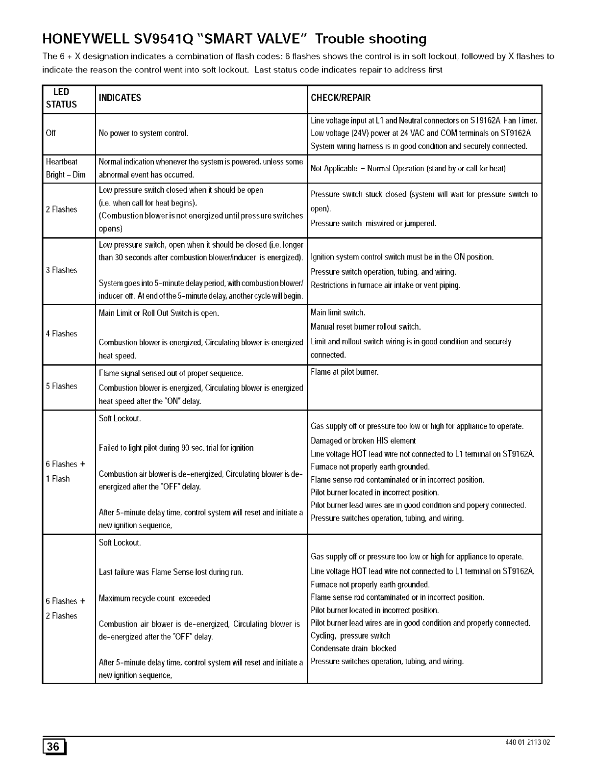
HONEYWELL SV9541Q "SMART VALVE" Trouble shooting
The 6 + X designation indicates a combination of flash codes: 6 flashes shows the control is in soft lockout, followed by X flashes to
indicate the reason the control went into soft lockout. Last status code indicates repair to address first
LED INDICATES CHECK/REPAIR
STATUS
Line voltageinput at L1 and Neutral connectors on ST9162A FanTimer.
Off No power to system control. Low voltage (24V) power at 24 VAC and COM terminals on ST9162A
System wiring harness is in good condition and securely connected.
Heartbeat Normal indication whenever the system is powered, unless some
Bright - Dim abnormal event has occurred. Not Applicable - Normal Operation (stand by or call for heat)
Low pressure switch closed when it should be open Pressure switch stuck closed (system will wait for pressure switch to
2 Flashes (i.e. when call for heat begins), open).
(Combustion blower is not energized until pressure switches
opens) Pressure switch miswired orjumpered.
Low pressure switch, open when it should be closed (i.e. longer
than 30 seconds after combustion blower/inducer is energized).
3 Flashes
4 Flashes
5 Flashes
6 Flashes+
1 Flash
6 Flashes+
2 Flashes
System goes into 5-minute delay period, with combustion blower/
inducer off. At end of the 5-minute delay, another cycle will begin.
Main Limit or Roll Out Switch is open.
Combustion blower is energized, Circulating blower is energized
heat speed.
Flame signal sensed out of proper sequence.
Combustion blower is energized, Circulating blower is energized
heat speed after the "ON" delay.
Soft Lockout.
Failed to light pilot during 90 sec. trial for ignition
Combustion air blower is de-energized, Circulating blower isde-
energized after the "OFF" delay.
After 5-minute delay time, control system will reset and initiate a
new ignition sequence,
SoftLockout.
Last failure was Flame Sense lost during run.
Maximum recycle count exceeded
Combustion air blower is de-energized, Circulating blower is
de-energized after the "OFF" delay.
After 5-minute delay time, control system will reset and initiate a
new ignition sequence,
Ignition system control switch must be in the ON position.
Pressure switch operation, tubing, and wiring.
Restrictions in furnace air intake or vent piping.
Main limit switch.
Manual reset burner rollout switch.
Limit and rollout switch wiring is in good condition and securely
connected.
Flame at pilot burner.
Gas supply off or pressure too low or high for appliance to operate.
Damaged or broken HIS element
Line voltage HOT lead wire not connected to L1 terminal on ST9162A.
Furnace not properly earth grounded.
Flame sense rod contaminated or in incorrect position.
Pilot burner located in incorrect position.
Pilot burner lead wires are in good condition and popery connected.
Pressure switches operation, tubing, and wiring.
Gas supply off or pressure too low or high for appliance to operate.
Line voltage HOT lead wire not connected to LI terminal on ST9162A.
Furnace not properly earth grounded.
Flame sense rod contaminated or in incorrect position.
Pilot burner located in incorrect position.
Pilot burner lead wires are in good condition and properly connected.
Cycling, pressure switch
Condensate drain blocked
Pressure switches operation, tubing, and wiring.
[_ 440 01 211302
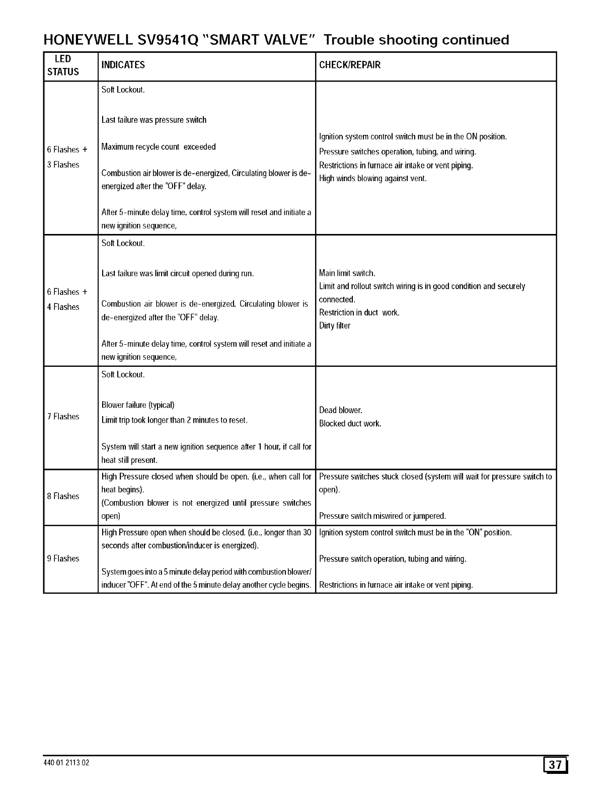
HONEYWELL SV9541Q "SMART VALVE" Trouble shooting continued
LED INDICATES CHECK/REPAIR
STATUS
Soft Lockout.
6 Flashes+
3 Flashes
6 Flashes+
4 Flashes
7 Flashes
8 Flashes
9 Flashes
Last failure was pressure switch
Maximum recycle count exceeded
Combustion air blower is de-energized, Circulating blower isde-
energized after the "OFF" delay.
After 5-minute delay time, control system will reset and initiate a
new ignition sequence,
Soft Lockout.
Last failure was limit circuit opened during run.
Combustion air blower is de-energized, Circulating blower is
de-energized after the "OFF" delay.
After 5-minute delay time, control system will reset and initiate a
new ignition sequence,
Soft Lockout.
Blowerfailure(typical)
Limittriptooklongerthan2 minutesto reset.
System will start a new ignition sequence after 1 hour, if call for
heat still present.
High Pressure closed when should be open. (i.e., when call for
heat begins).
(Combustion blower is not energized until pressure switches
open)
High Pressure open when should be closed. (i.e., longer than 30
seconds after combustion/inducer is energized).
System goes into a 5 minute delay period with combustion blower/
inducer"OFF". At end of the 5minute delay another cycle begins.
Ignition system control switch must be in the ON position.
Pressure switches operation, tubing, and wiring.
Restrictions in furnace air intake or vent piping.
High winds blowing against vent.
Main limit switch.
Limit and rollout switch wiring is in good condition and securely
connected.
Restriction in duct work.
Dirty filter
Deadblower.
Blockedductwork.
Pressure switches stuck closed (system will wait for pressure switch to
open).
Pressure switch miswired orjumpered.
Ignition system control switch must be in the "ON" position.
Pressure switch operation, tubing and wiring.
Restrictions in furnace air intake or vent piping.
44001 211302 [_
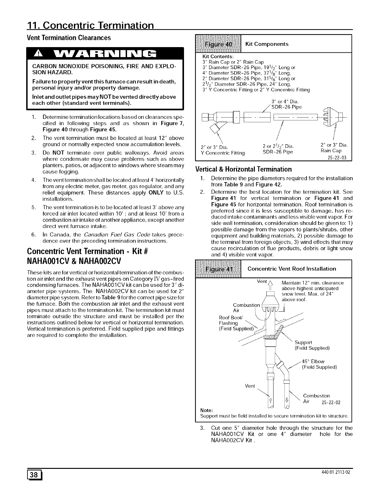
11. Concentric Termination
Vent Termination Clearances
CARBON MONOXIDE POISONING, FIRE AND EXPLO-
SION HAZARD.
Failure to properly vent this furnace can result in death,
personal injury and/or property damage.
Inlet and outlet pipes may NOT be vented directly above
each other (standard vent terminals).
1. Determine termination locations based on clearances spe-
cified in following steps and as shown in Figure 7,
Figure 40 through Figure 45.
2. The vent termination must be located at least 12" above
ground or normally expected snow accumulation levels.
3. Do NOT terminate over public walkways. Avoid areas
where condensate may cause problems such as above
planters, patios, or adjacent to windows where steam may
cause fogging.
4. The vent termination shall be located at least 4' horizontally
from any electric meter, gas meter, gas regulator, and any
relief equipment. These distances apply ONLY to U.S.
installations.
The vent termination is to be located at least 3' above any
forced air inlet located within 10' ;and at least 10' from a
combustion air intake of another appliance, except another
direct vent furnace intake.
6. In Canada, the Canadian Fuel Gas Code takes prece-
dence over the preceding termination instructions.
Concentric Vent Termination - Kit #
NAHA001CV& NAHA002CV
These kits are for vertical or horizontal termination of the combus-
tion air inlet and the exhaust vent pipes on Category IV gas-fired
condensing furnaces. The NAHA001 CV kit can be used for 3" di-
ameter pipe systems. The NAHA002CV kit can be used for 2"
dia meter pipe system. Refer to Table 9 for the correct pipe size for
the furnace. Both the combustion air inlet and the exhaust vent
pipes must attach to the termination kit. The termination kit must
terminate outside the structure and must be installed per the
instructions outlined below for vertical or horizontal termination.
Vertical termination is preferred. Field supplied pipe and fittings
are required to complete the installation.
Kit Contents:
Kit Components
3" Rain Cap or 2" Rain Cap 1
3" Diameter SDR-26 Pipe, 19 /2" Long or
4" Diameter SDR-26 Pipe, 371/8" Long,
2" Diameter SDR-26 Pipe, 315/8" Long or
21/2" Diameter SDR-26 Pipe, 24" Long,
3" Y Concentric Fitting or 2" Y Concentric Fitting
3" or 4" Dia.
2" or 3" Dia. 2 or 21/2" Dia. 2" or 3" Dia.
Y Concentric Fitting SDR-26 Pipe Rain Cap
25-22-03
Vertical & Horizontal Termination
1,
2.
Determine the pipe diameters required for the installation
from Table 9 and Figure 42.
Determine the best location for the termination kit. See
Figure41 for vertical termination or Figure41 and
Figure 45 for horizontal termination. Roof termination is
preferred since it is less susceptible to damage, has re-
duced intake contaminants and less visible vent vapor. For
side wall termination, consideration should be given to: 1)
possible damage from the vapors to plants/shrubs, other
equipment and building materials, 2) possible damage to
the terminal from foreign objects, 3) wind effects that may
cause recirculation of flue products, debris or light snow
and 4) visible vent vapor.
Concentric Vent Roof Installation
Vent
Combustion
Air
Roof Boot/
Flashing _
(Field Supplied)
Maintain 12" min. clearance
above highest anticipated
snow level. Max. of 24"
above roof.
Support
(Field Supplied)
j45 Elbow
(Field Supplied)
Vent
Combustion
Air 25-22-02
Note:
Support must be field installed to secure termination kit to structure.
3. Cut one 5" diameter hole through the structure for the
NAHA001CV Kit or one 4" diameter hole for the
NAHA002CV Kit.
[_ 440 01 211302
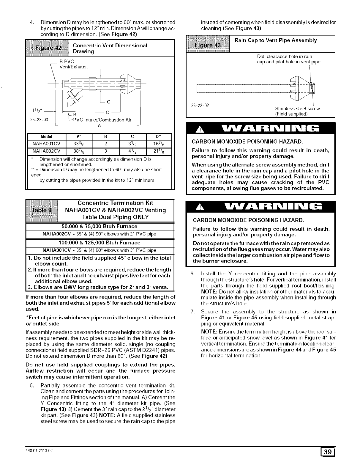
4. DimensionDmaybelengthenedto 60" max. or shortened
by cutting the pipes to 12" min. Dimension Awill change ac-
cording to D dimension. (See Figure 42)
i: i
Concentric Vent Dimensional
Drawing
B PVC
__i Vent/Exhaust
211/222_03 _PVC ,ntake/comDbust,on Air
A
Model A_ B C D**
NAHA001CV 33_/8 2 31/2 16//8
NAHA002CV 38//8 3 41/2 211/8
= Dimension will change accordingly as dimension D is
lengthened or shortened.
** = Dimension D may be lengthened to 60" may also be short-
ened
by cutting the pipes provided in the kit to 12" minimum
Concentric Termination Kit
NAHA001CV &NAHA002VC Venting
.... Table Dual Piping ONLY
50,000 & 75,000 Btuh Furnace
NAHA002CV - 35' & (4) 90 ° elbows with 2" PVC pipe
100,000 & 125,000 Btuh Furnace
NAHA001CV - 35' & (4) 90 ° elbows with 3" PVC pipe
1. Do not include the field supplied 45 ° elbow in the total
elbow count.
2. If more than four elbows are required, reduce the length
of both the inlet and the exhaust pipes five feet for each
additional elbow used.
3. Elbows are DWV long radius type for 2" and 3" vents.
If more than four elbows are required, reduce the length of
both the inlet and exhaust pipes 5' for each additional elbow
used.
*Feet of pipe is whichever pipe run is the longest, either inlet
or outlet side.
If assembly needs to be extended to meet height or side wall thick-
ness requirement, the two pipes supplied in the kit may be re-
placed by using the same diameter solid, single (no coupling
connections) field supplied SDR-26 PVC (ASTM D2241) pipes.
Do not extend dimension D more than 60". (See Figure 42)
Do not use field supplied couplings to extend the pipes.
Airflow restriction will occur and the furnace pressure
switch may cause intermittent operation.
5. Partially assemble the concentric vent termination kit.
Clean and cement the parts using the procedures for Join-
ing Pipe and Fittings section of the manual. A) Cement the
Y Concentric fitting to the 4" diameter kit pipe. (See
Figure 43) B) Cement the 3" rain cap to the 21/2" diameter
kit part. (See Figure 43) NOTE: A field supplied stainless
steel screw may be used to secure the rain cap to the pipe
instead of cementing when field disassembly is desired for
cleaning (See Figure 43)
Rain Cap to Vent Pipe Assembly
Drill clearance hole in rain
cap and pilot hole in vent pipe.
Stainless steel screw
(Field supplied)
CARBON MONOXIDE POISONING HAZARD.
Failure to follow this warning could result in death,
personal injury and/or property damage.
When using the alternate screw assembly method, drill
a clearance hole in the rain cap and a pilot hole in the
vent pipe for the screw size being used. Failure to drill
adequate holes may cause cracking of the PVC
components, allowing flue gases to be recirculated.
CARBON MONOXIDE POISONING HAZARD.
Failure to follow this warning could result in death,
personal injury and/or property damage.
Do not operate the furnace with the rain cap removed as
recirulation of the flue gases may occur. Water may also
collect inside the larger combustion air pipe and flowto
the burner enclosure.
Install the Y concentric fitting and the pipe assembly
through the structure's hole. For vertical termination, install
the parts through the field supplied roof boot/flashing.
NOTE: Do not allow insulation or other materials to accu-
mulate inside the pipe assembly when installing through
the structure's hole.
Secure the assembly to the structure as shown in
Figure 41 or Figure 45 using field supplied metal strap-
ping or equivalent material.
NOTE: Ensure the termination height is above the roof sur-
face or anticipated snow level as shown in Figure 41 for
vertical termination. Ensure the termination location clear-
ance dimensions are as shown in Figure 44 and Figure 45
for horizontal termination.
44001 211302 E_
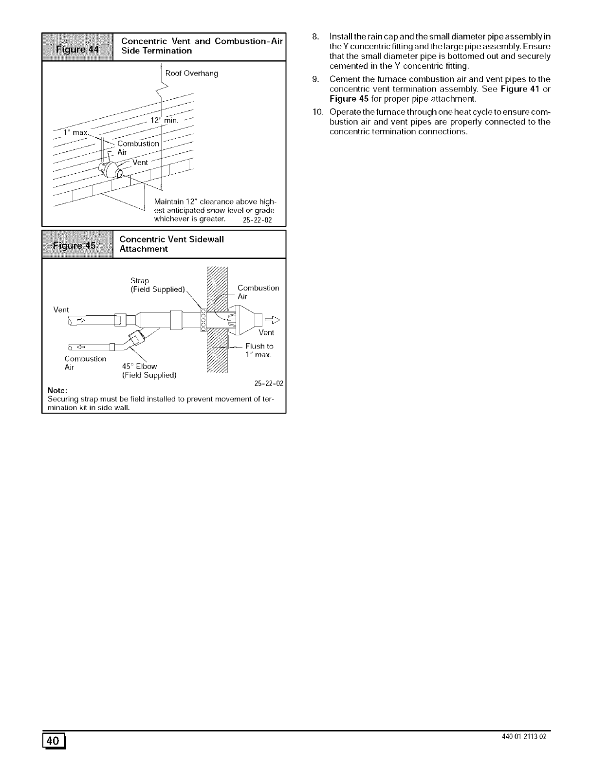
ConcentricVentandCombustion-Air
SideTermination
RoofOverhang
12"min.J_
Maintain12"clearanceabovehigh-
estanticipatedsnowlevelorgrade
whicheverisgreater. 25-22-02
ConcentricVentSidewall
Attachment
Strap
(FieldSupplied)\ _//JJ/_Combustion
\
Vent o
Vent
_//_f_l-_ Flush to
Combustion _ _ 1" max.
Air 4S°E bow
(Field Supplied) 25-22-02
Note:
Securing strap must be field installed to prevent movement of ter-
mination kit in side wall,
8. Install the rain cap and the small diameter pipe assembly in
the Y concentric fitting and the large pipe assembly. Ensure
that the small diameter pipe is bottomed out and securely
cemented in the Y concentric fitting.
9. Cement the furnace combustion air and vent pipes to the
concentric vent termination assembly. See Figure 41 or
Figure 45 for proper pipe attachment.
10. Operate the furnace through one heat cycle to ensure com-
bustion air and vent pipes are properly connected to the
concentric termination connections.
[_ 440 01 211302
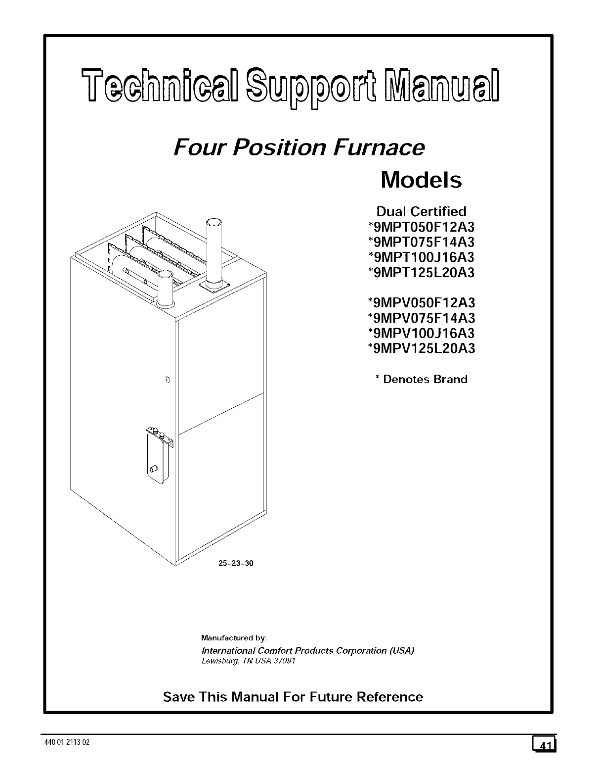
Four Position Furnace
Models
Dual Certified
*9MPT050F12A3
*9MPT075F14A3
*9MPT100J16A3
*9MPT125L20A3
*9MPV050F12A3
*9MPV075F14A3
*9MPV100J16A3
*9MPV125L20A3
* Denotes Brand
25-23-30
Manufactured by:
International Comfort Products Corporation (USA)
Lewisburg, TN USA 37091
Save This Manual For Future Reference
44001 211302 [_
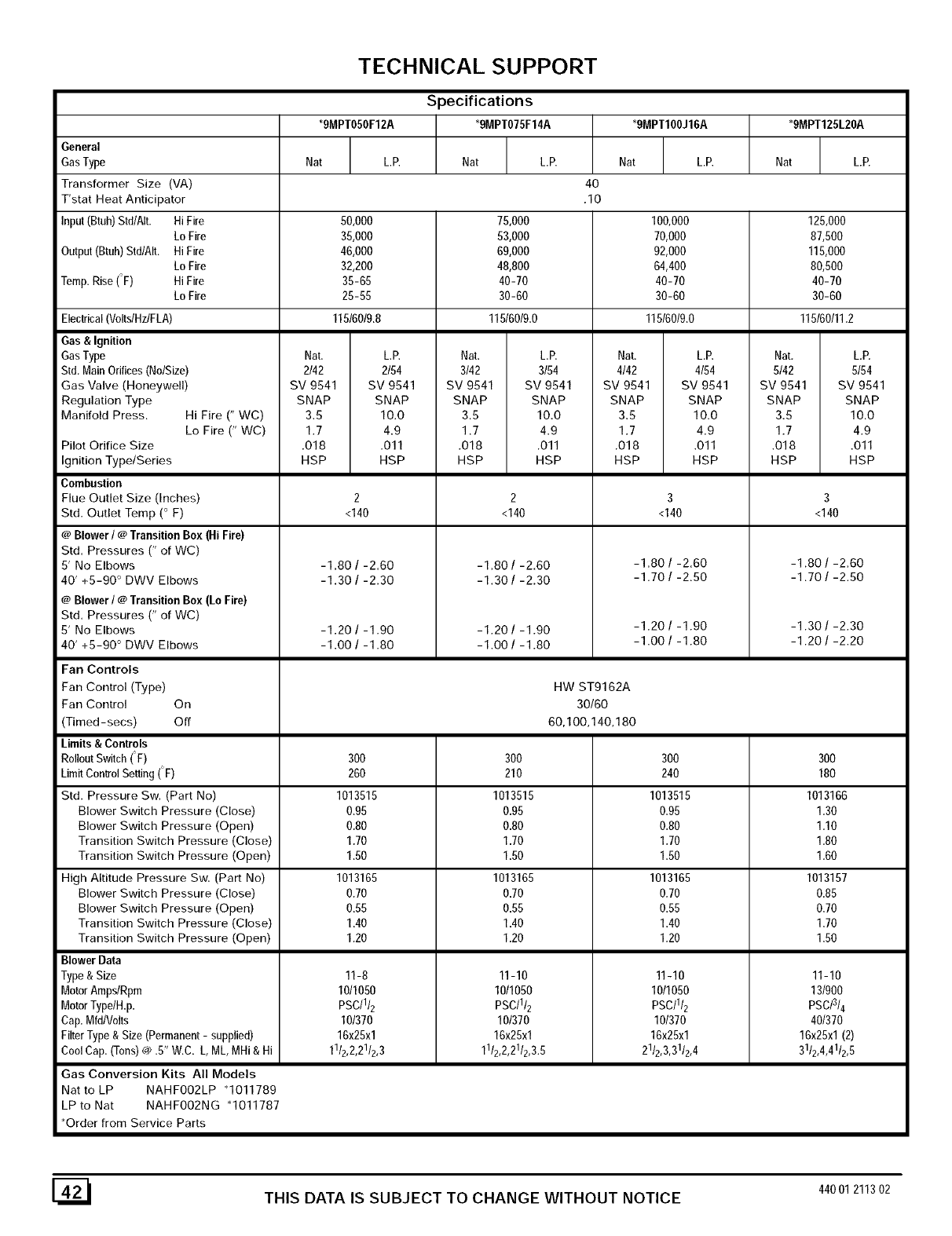
TECHNICAL SUPPORT
Specifications
_9MPTO50F12A _9MPTO75F14A _9MPT100J16A *gMPT125L20A
General
GasType Nat L.P. Nat L.P. Nat LP. Nat LP.
Transformer Size (VA) 40
T'stat Heat Anticipator .10
Input(Btuh)Std/AIt. Hi Fire 50,000 75,000 100,000 125,000
Lo Fire 35,000 53,000 70,000 87,500
Output(Btuh)Std/AIt. HiFire 46,000 69,000 92,000 115,000
Lo Fire 32,200 48,800 64,400 80,500
Temp. Rise (F) Hi Fire 35-65 40-70 40-70 40-70
Lo Fire 25-55 30-60 30-60 30-60
115/60/9.8 115/60/9.0 115/60/9.0 115/60/11.2
Nat. L.P. Nat. L.P. Nat. L.P. Nat. L.P.
2/42 2/54 3/42 3/54 4/42 4/54 5142 5154
SV 9541 SV 9541 SV 9541 SV 9541 SV 9541 SV 9541 SV 9541 SV 9541
SNAP SNAP SNAP SNAP SNAP SNAP SNAP SNAP
3.5 10.0 3.5 10.0 3.5 10.0 3.5 10.0
1.7 4.9 1.7 4.9 1.7 4.9 1.7 4.9
.018 .011 .018 .011 .018 .011 .018 .011
HSP HSP HSP HSP HSP HSP HSP HSP
Electrical(Volts/Hz/FLA)
Gas & Ignition
GasType
Std.MainOrifices (No/Size)
Gas Valve (Honeywell)
Regulation Type
Manifold Press. Hi Fire (" WC)
Lo Fire (" WC)
Pilot Orifice Size
Ignition Type/Series
Combustion
Flue Outlet Size (Inches)
Std. Outlet Temp (° F)
@Blower/@ Transition Box (HiFire)
Std. Pressures (" of WC)
5' No Elbows
40' +5-90 ° DWV Elbows
@Blower/@ Transition Box (Lo Fire)
Std. Pressures (" of WC)
5' No Elbows
40' +5-90 ° DWV Elbows
Fan Controls
Fan Control (Type)
Fan Control On
(Timed-secs) Off
Limits & Controls
RolloutSwitch(F)
LimitControl Setting(F)
Std. Pressure Sw. (Part No)
Blower Switch Pressure (Close)
Blower Switch Pressure (Open)
Transition Switch Pressure (Close)
Transition Switch Pressure (Open)
High Altitude Pressure Sw. (Part No)
Blower Switch Pressure (Close)
Blower Switch Pressure (Open)
Transition Switch Pressure (Close)
Transition Switch Pressure (Open)
Blower Data
Type & Size
MotorAmps/Rpm
MotorType/H.p.
Cap.MfdNolts
FilterType& Size (Permanent- supplied)
CoolCap. (Tons)@ .5" W.C. L, ML, MHi& Hi
Gas Conversion Kits All Models
Nat to LP NAHFOO2LP q011789
LP to Nat NAHFOO2NG q011787
_Order from Service Parts
2
<140
-1.80 /-2.60
-1.30 /-2.30
-1.20 /-1.90
-1.00 /-1.80
2
<140
-1.80 /-2.60
-1.30 /-2.30
-1.20 /-1.90
-1.00 /-1.80
3
<140
-1.80 /-2.60
-1.70 /-2.50
-1.20 /-1.90
-1.00 /-1.80
HW ST9162A
30/60
60,100,140,180
300
26O
1013515
0.95
0.80
1.70
1.50
1013165
0.70
0.55
1.40
1.20
11-8
10/1050
PSC/I/2
10/370
16x25xl
1112,2,21/2,3
300
210
1013515
0.95
0.80
1.70
1.50
1013165
0.70
0.55
1.40
1.20
11-10
1011050
PSC/II2
10/370
16x25xl
1112,2,2112,3.5
300
240
1013515
0.95
0.80
1.70
1.50
1013165
0.70
0.55
1.40
1.20
11-10
10/1050
PSC/I/2
10/370
16x25xl
2112,3,31/2,4
3
<140
-1.80 /-2.60
-1.70/-2.50
300
180
1013166
1.30
1.10
1.80
1.60
1013157
0.85
0.70
1.70
1.50
11-10
13N00
PSC/3/4
40/370
16x25x1(2)
3112,4,41/2,5
[_1 THIS DATA IS SUBJECT TO CHANGE WITHOUT NOTICE 44001211302
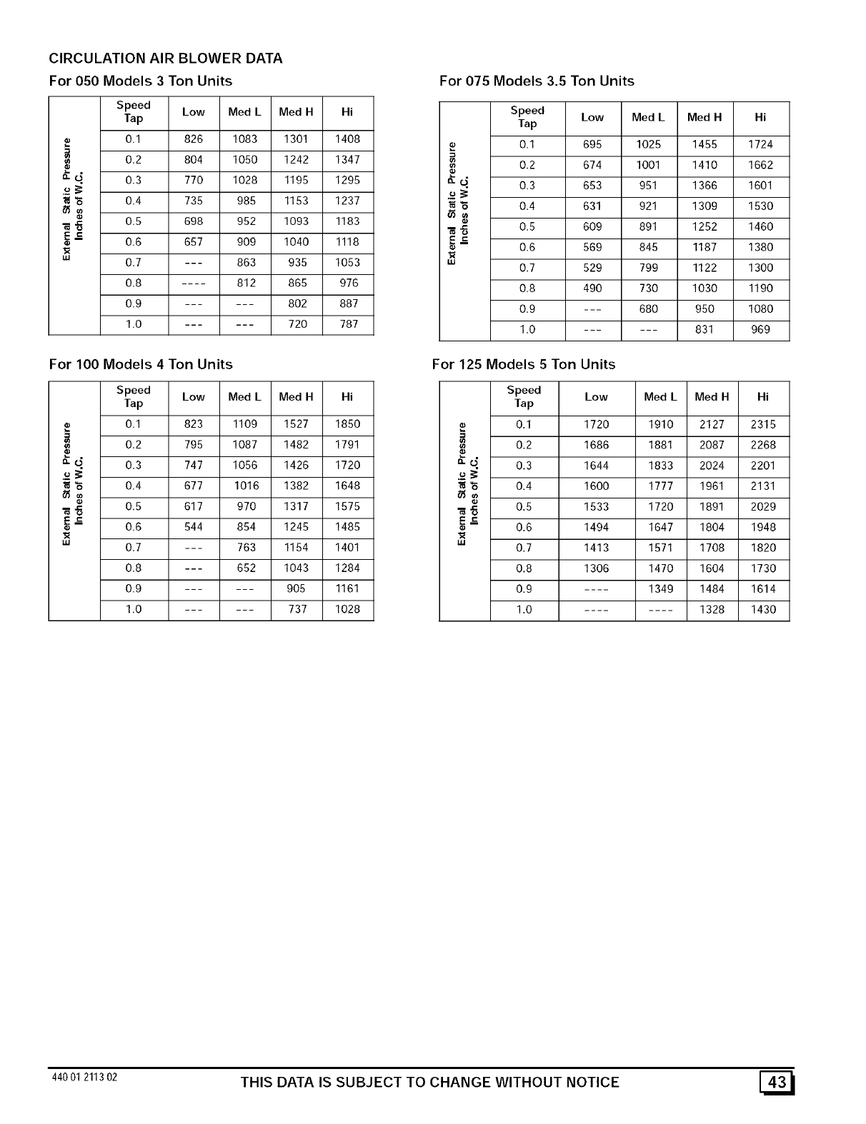
CIRCULATIONAIRBLOWERDATA
For050Models3TonUnits
Speed Low Med L Med H Hi
Tap
0.1 828 1083 1301 1408
0.2 804 1050 1242 1347
q 0.3 770 1028 1195 1295
.93"6 0.4 735 985 1153 1237
_ 0.5 698 952 1093 1183
E_
® 0.6 657 909 1040 1118
w 0.7 --- 863 935 1053
0.8 .... 812 865 976
0.9 ...... 802 887
1.0 ...... 720 787
For 100 Models 4 Ton Units
Speed Low Med L Med H Hi
Tap
0.1 823 1109 1527 1850
0.2 795 1087 1482 1791
q 0.3 747 1056 1426 1720
.93"6 0.4 677 1016 1382 1648
_ 0.5 617 970 1317 1575
E_ 0.6 544 854 1245 1485
w0.7 --- 763 1154 1401
0.8 --- 652 1043 1284
0.9 ...... 905 1161
1.0 ...... 737 1028
For 075 Models 3.5 Ton Units
Speed Low Med LMed H Hi
Tap
._ 0.1 695 1025 1455 1724
0.2 674 1001 1410 1662
_" o." 0.3 653 951 1366 1601
.£ 3
"6 0.4 631 921 1309 1530
6_0_
-_ -_ 0.5 609 891 1252 1460
E_= 0.6 569 845 1187 1380
I,U 0.7 529 799 1122 1300
0.8 490 730 1030 1190
0.9 --- 680 950 1080
1.0 ...... 831 969
For 125 Models 5 Ton Units
Speed Low Med LMed H Hi
Tap
0.1 1720 1910 2127 2315
0.2 1686 1881 2087 2268
q 0.3 1644 1833 2024 2201
.93
"6 0.4 1600 1777 1961 2131
_ 0.5 1533 1720 1891 2029
E_ 0.6 1494 1647 1804 1948
w0.7 1413 1571 1708 1820
0.8 1306 1470 1604 1730
0.9 .... 1349 1484 1614
1.0 ........ 1328 1430
44001211302 THIS DATA IS SUBJECT TO CHANGE WITHOUT NOTICE [_
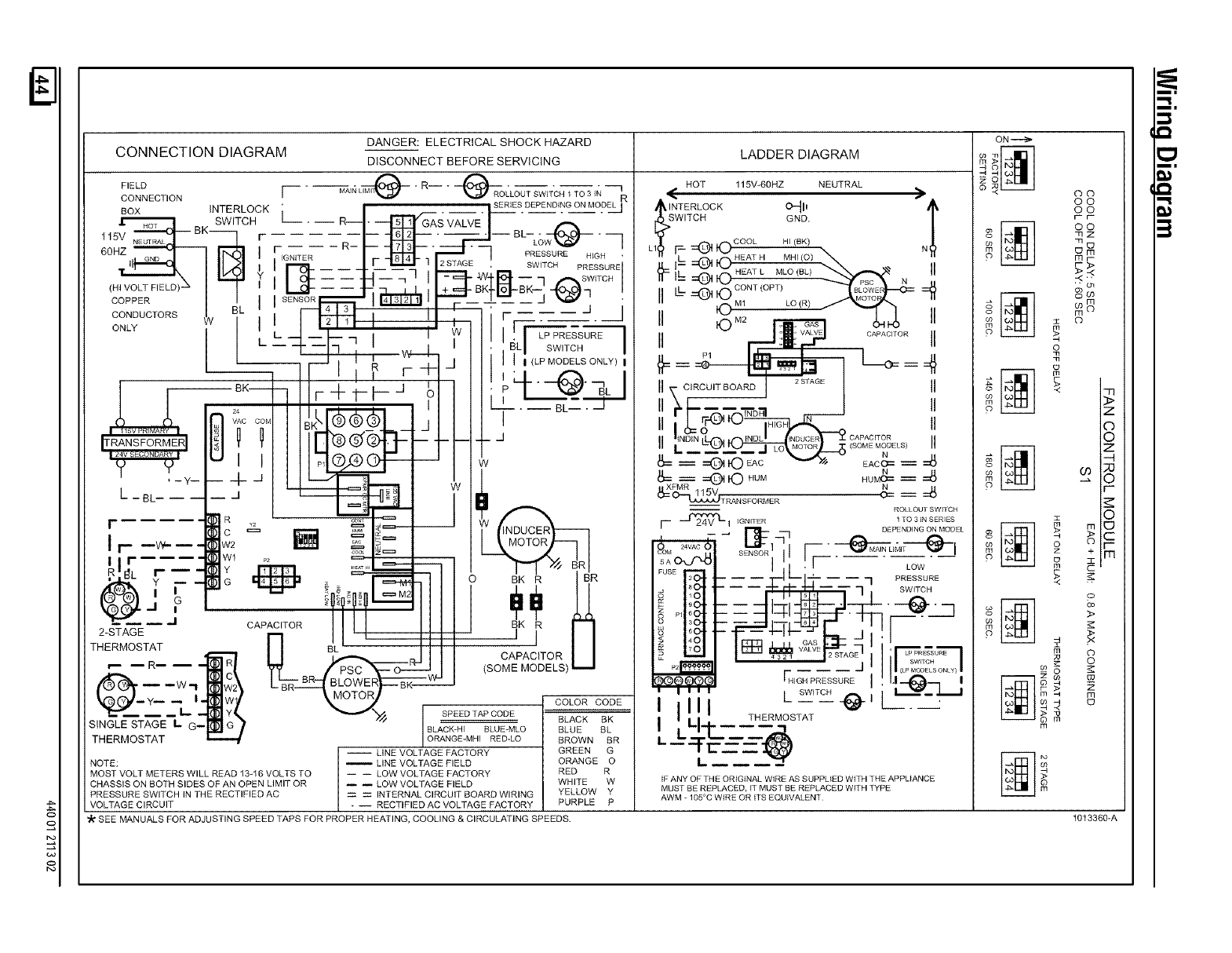
DANGER: ELECTRICAL SHOCK HAZARD
CONNECTION DIAGRAM DISCONNECT BEFORE SERVICING
FIELD LiMli_ " Ri * i_RO
CONNECT,ON r _,_ _<o_-m_,_c__To_I_--_
BOX INTERLOCK L _ __ SERIES DEPENDING ONMODEL I
E SWITCH --- -- R--- • _ _ "_ GFAS VALVE
--BK_ _ BL--- _'_ -
115V NEUTRAL / r _ -- I---- LOW-_---- --7
60HZ ( _ FIGNITE R _1 _ i7 3 _ "7PRESSURE H GH "
GND _ 8 4 i ,]
,_ II _,1 __ _. E.-__- 2STAGE. SW,TOHPRESSURd
(HI VOLT FIELD) -_ -- +
--" -q _ BK'iil_ B K-- -I I
COPPER / I SE"S_7 i_r_r_ I .... J _ '
CONDUCTORS 7 BL _ _ F- -- -- -- / /
o I _ "_"
eLv I L__ w F--_ss_--m
IL.... 17 '. I ,,, i I '.:aL I SWiTCH_
I - --- _ L_-_i I Ii,<LPMODELS ONLY) I
___ii I I '!" FTI Ii;I #%_ I
I r--i°Ki- ,-+-r-P-" ,_1 :,r__---_J
/ / 24 -- i i I I I,,_---BL----J
: ....... =Kt ®®® I , I I
FRANSFORMERI i i l L m m2_ _ p_ ....
- _ I : ®#e_l -_ w
. ,-Y--€- -i__ 1 w
L-BL .... _ I _ _ _
_=_ i !1
,_..... R __'_ ,__
c _ _
i _v+._. w_ [] _ _= I I ?sT_<;,_,7
r c<_ z = I _ #I I
I I r.... wl _ : -_ W_. d_l
._L F---: : _ _1 o BIKIR-"7'_R
2-STAGE --, _ -------_-L-i-- --- I
THERMOSTAT r l BL _ illllid I
,_ /I ;A I I t CAPACITOR
-- R-- -- -- I_ RI _l KPSC_------O--_,.,I(SOME MODELS) --
_---w_ iiw2\ L BRi--_ BLOW_ERF -FF-2_-_
L_ -- _ _ y( _ SPEED TAP CODE -- --
_ _ _ - _// _ _ BLACK BK
S,N_LESTA_E_--l! G) ISLAC*-H,SLOE-MLOBLOEBL
THERMOSTAT _ I O_NGE-MHI RED-LO BROWN BR
i LINE VOLTAGE FACTORY GREEN G
NOTE: _ LINE VOLTAGE FIELD ORANGE O
MOST VOLT METERS WILL READ 13-16 VOLTS TO i -- LOW VOLTAGE FACTORY RED R
CHASSIS ON BOTH SIDES OF AN OPEN LIMIT OR _ _ LOW VOLTAGE FIELD WHITE W
PRESSURE SWITCH IN THE RECTIFIED AC INTERNAL CIRCUIT BOARD WIRING YELLOW Y
VOLTAGE CIRCUIT RECTIFIED AC VOLTAGE FACTORY PURPLE P
SEE MANUALS FOR ADJUSTING SPEED TAPS FOR PROPER HEATING, COOLING & CIRCULATING SPEEDS,
LADDER DIAGRAM
HOT 115V-60HZ NEUTRAL
's"w_,Vc_°CK_'_. "
F _ _ COOL HI (BK) N
LI_ _ .... HEATH MHI (O)
_- I- =_mJ _ _ II
_- IL _ _-_ HEAT L MLO (BL) _W
L _ "_J CONT(OPT) N
II ©M_ r_ &_ II
II r..ji§ _ OA"AORORII
=4
II T CiROUnBOARD _,,GE II
II \l_ F "-A..--,-,_o_ NFm----i II
IIL-R__%_t_}_f; <SOM_MODELS,ii
-- _TO":Ar W EAO&= =_
.= =_ © HUM N
HUMC== _ :_
II XFMR 5V N
_ _T_NSFORMER _ __
ROLLOUTSWITCH
--_I IGNITER 1TO 3 IN SERIES
r_- DEPENDING ON MODEL
_EN_OR'l Fi _L'M'_I
_A_ I ',i'.m'--"---:-_ow"--
2 0 -- -- _ _ _ I _ i J q PRESSURE
to° .... ,_rt _,-- a SWITCR
_O .....
o_,0o-- 4i_1_.---7_-e._:.m
:o°i:-P--._-_-4---_Eif!
S
IHIGH PRESSURE I ' 1--_ I
I I I I I / SWITCH _ / _--_
I III _ii_[ .
THERMOSTAT
1
IF ANY OF THE ORIGINAL WIRE AS SUPPLIED WiTH THE APPLIANCE
MUST BE REPLACED. tT MUST BE REPLACED WITH TYPE
AWM 105°C WIRE OR ITS EQUIVALENT
ON---_
_ oo
CO
CO
r-r-
oo
mE]
m_ _m
© mr-
r->
_ _ o
$
n_
_ _ m
o Z
©
o
©
o F-
o
o +m
_ >
>
$ o
©
__o_ g
-4 m
S
m
1013360-A
l
I
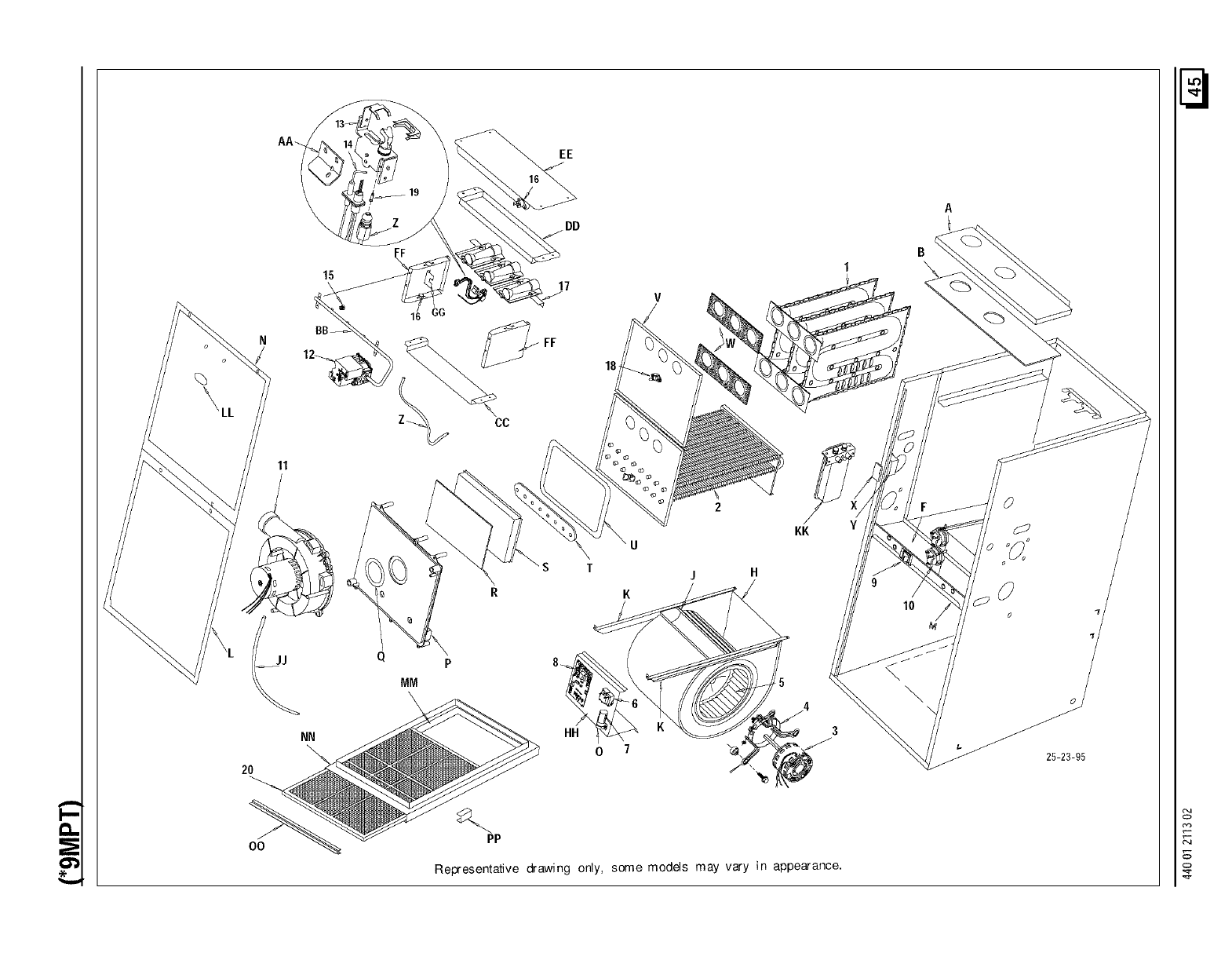
E
2O
OO
11
NN
15
16 GG
EE
17 V
FF
18
CC
jH
KK
P
MM
HH
O7
PP
Representative drawing only, some models may vary in appearance.
\
25-23-95
o
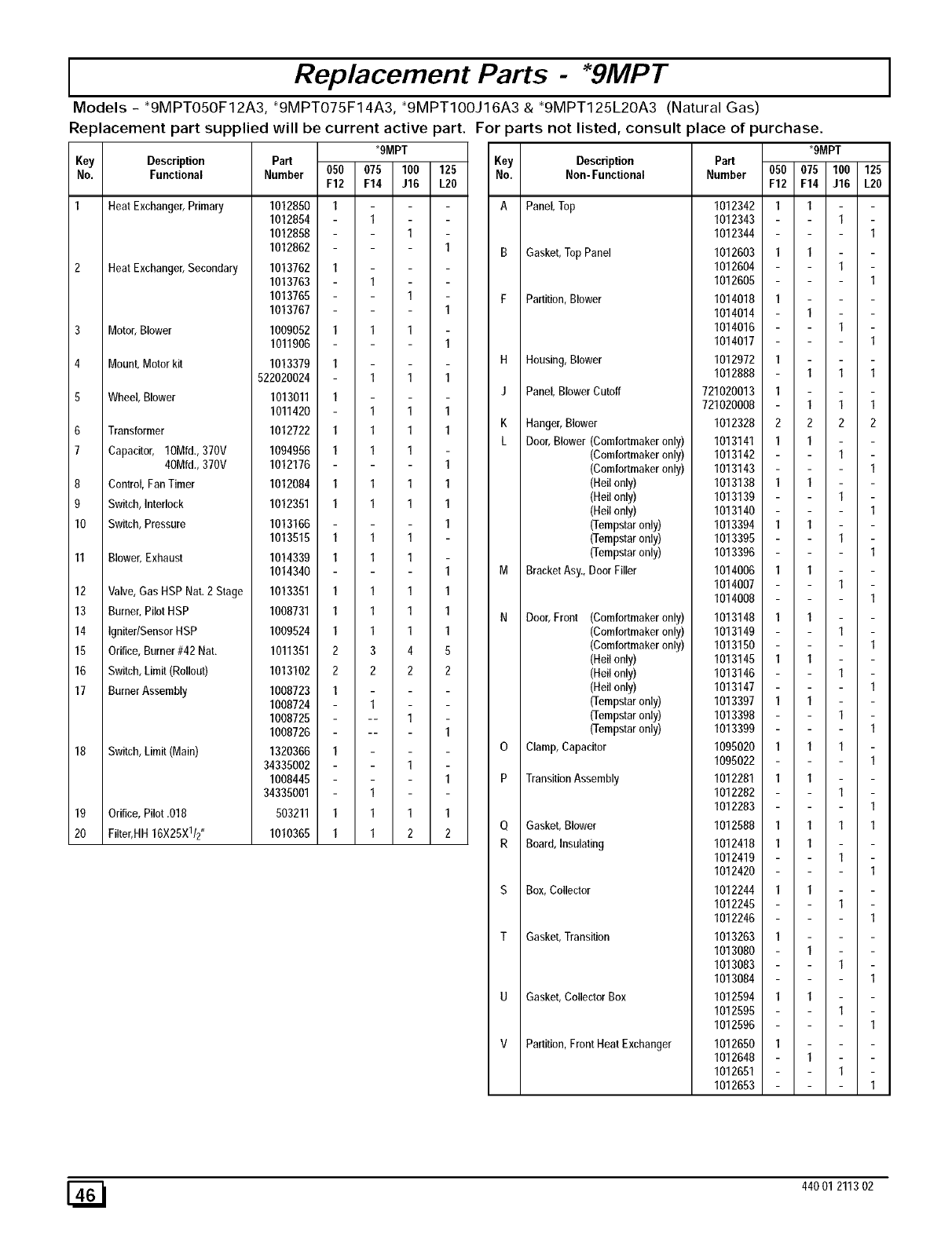
IReplacement Parts - *9MPT
Models - _9MPTO5OF12A3, _9MPTO75F14A3, _9MPTIOOJ16A3 8, _9MPT125L2OA3 (Natural Gas)
Replacement part supplied will be current active part. For _arts not listed, consult place of purchase.
*gMPT
Key Description Part Key Description Part
No. Functional Number No. Non-Functional Number 050 075 100 125
*gMPT
050 075 100 125
F12 F14 J16 L20
1 Heat Exchange_Prima_
2 Heat Exchanger,Secondary
3 Motor,Blower
4 Mount, Motor kit
5Wheel, Blower
6Transformer
7 Capacitor, 10Mfd.,370V
40MN., 370V
8 Control,FanTimer
9 Switch,Interlock
10 Switch,Pressure
11 Blower,Exhaust
12 Valve,Gas HSP Nat.2 Stage
13 Burner,PilotHSP
14 Igniter/SensorHSP
15 Orifice,Burner#42 Nat.
16 Switch,Limit(Rollout)
17 BurnerAssembly
18 Switch,Limit(Main)
19 Orifice,Pilot .018
20 Filter,HH16X25X112"
1012850 1
1012854 1
1012858 1
1012862 1
1013762 1
1013763 1
1013765 1
1013767 1
1009052 1 1 1
1011906 1
1013379 1
522020024 1 1 1
1013011 1
1011420 1 1 1
1012722 1 1 1 1
1094956 1 1 1
1012176 1
1012084 1 1 1 1
1012351 1 1 1 1
1013166 1
1013515 1 1 1
1014339 1 1 1
1014340 1
1013351 1 1 1 1
1008731 1 1 1 1
1009524 1 1 1 1
1011351 2 3 4 5
1013102 2 2 2 2
1008723 1
1008724 1
1008725 -- 1
1008726 -- 1
1320366 1
34335002 1
1008445 1
34335001 1
503211 1 1 1 1
1010365 1 1 2 2
A Panel, Top
B Gasket,TopPanel
F Partition,Blower
H Housing,Blower
J Panel, BlowerCutoff
KHanger, Blower
F12 F14 J16 L2O
1012342 I I
1012343 I
1012344 I
1012603 I I
1012604 I
1012605 I
1014018 I
1014014 I
1014016 I
1014017 I
1012972 I
1012888 I I I
721020013 I
721020008 I I I
1012328 2 2 2 2
L Door,Blower (Comfortmakeronly)
(Comfortmakeronly)
(Comfortmakeronly)
(Hellonly)
(Hellonly)
(Hellonly)
(Tempstaronly)
(Tempstaronly)
(Tempstaronly)
M BracketAsy.,Door Filler
N Door,Front (Comfortmakeronly)
(Comfortmakeronly)
(Comfortmakeronly)
(Hellonly)
(Hellonly)
(Hellonly)
(Tempstaronly)
(Tempstaronly)
(Tempstaronly)
O Clamp,Capacitor
P TransitionAssembly
Q Gasket, Blower
R Board, Insulating
S Box, Collector
T Gasket,Transition
U Gasket,CollectorBox
V Partition, Front Heat Exchanger
1013141 1 1
1013142 1
1013143 1
1013138 1 1
1013139 1
1013140 1
1013394 1 1
1013395 1
1013396 1
1014006 1 1
1014007 1
1014008 1
1013148 1 1
1013149 1
1013150 1
1013145 1 1
1013146 1
1013147 1
1013397 1 1
1013398 1
1013399 1
1095020 1 1 1
1095022 1
1012281 1 1
1012282 1
1012283 1
1012588 1 1 1 1
1012418 1 1
1012419 1
1012420 1
1012244 1 1
1012245 1
1012246 1
1013263 1
1013080 1
1013083 1
1013084 1
1012594 1 1
1012595 1
1012596 1
1012650 1
1012648 1
1012651 1
1012653 1
440 01 211302
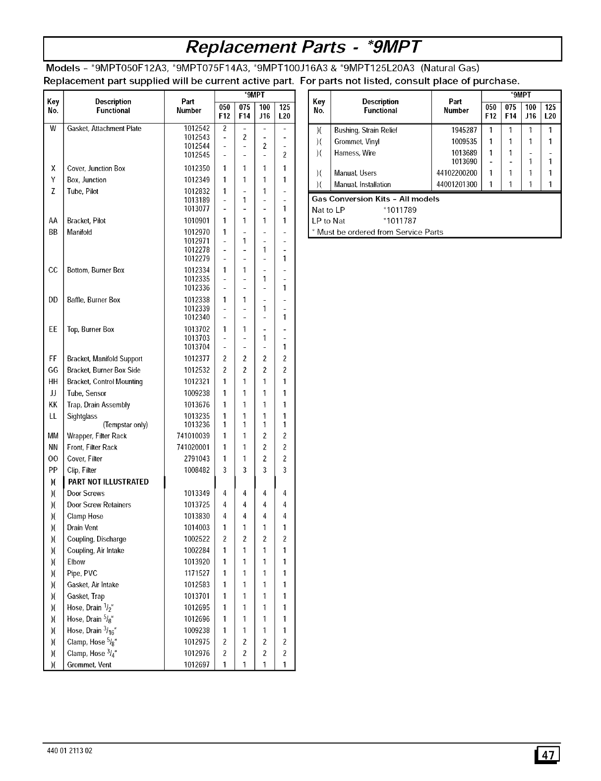
IReplacement Parts - *9MPT
Models - _9MPTO50F12A3, _9MPTO75F14A3, _9MPTIOOJ16A3 & _9MPT125L20A3 (Natural Gas)
Replacement part supplied will be current active part. For parts not listed, consult place of purchase.
_9MPT
Key Description Part Key Description Part
No, Functional Number 050 075 100 125 No, Functional Number
F12 F14 J16 L2O
W Gasket, Attachment Plate
X Cover,JunctionBox
Y Box,Junction
Z Tube, Pilot
AA Bracket,Pilot
BB Manifold
CC Bottom,BurnerBox
DD Baffle, Burner Box
EE Top,BurnerBox
FF Bracket,ManifoldSupport
GG Bracket,BurnerBoxSide
HH Bracket,ControIMounting
JJ Tube, Sensor
KK Trap,Drain Assembly
LL Sightglass (Tempstaronly)
MM Wrapper,FilterRack
NN Front,Filter Rack
OO Cover,Filter
PP Clip,Filter
)( PARTNOT ILLUSTRATED
)( Door Screws
)( Door ScrewRetainers
)( ClampHose
)( Drain Vent
)( Coupling,Discharge
)( Coupling,Air Intake
)( Elbow
)( Pipe,PVC
)( Gasket,Air Intake
)( Gasket,Trap
)( Hose,Drain 1/2"
)( Hose,Drain 5/8"
)( Hose,Drain 3/16"
)( Clamp,Hose5/8"
)( Clamp,Hose3/4"
)( Grommet,Vent
1012542 2
1012543
1012544
1012545
1012350 1
1012349 1
1012832 1
1013189
1013077
1010901 1
1012970 1
1012971
1012278
1012279
1012334 1
1012335
1012336
1012338 1
1012339
1012340
1013702 1
1013703
1013704
1012377 2
1012532 2
1012321 1
1009238 1
1013676 1
1013235 1
1013236 1
741010039 1
741020001 1
2791043 1
1008482 3
1013349 4
1013725 4
1013830 4
1014003 1
1002522 2
1002284 1
1013920 1
1171527 1
1012583 1
1013701 1
1012695 1
1012696 1
1009238 1
1012975 2
1012976 2
1012697 1
2
2
2
111
111
1
11
111
1
1
1
1
1
1
1
1
1
1
1
1
222
222
111
111
111
111
111
122
122
122
333
444
444
444
111
222
111
111
111
111
111
111
111
111
222
222
111
)( Bushing,Strain Relief
)( Grommet,Vinyl
)( Harness,Wire
)( Manual,Users
)( Manual,Installation
1945287 1
1009535 1
1013689 1
1013690
44102200200 1
44001201300 1
_9MPT
050 075 100 125
F12 F14 J16 L2O
111
111
1
1 1
111
111
Gas Conversion Kits - All models
Nat to LP _1011789
LP to Nat q011787
Must be ordered from Service Parts
440 01 211302 i_ ]
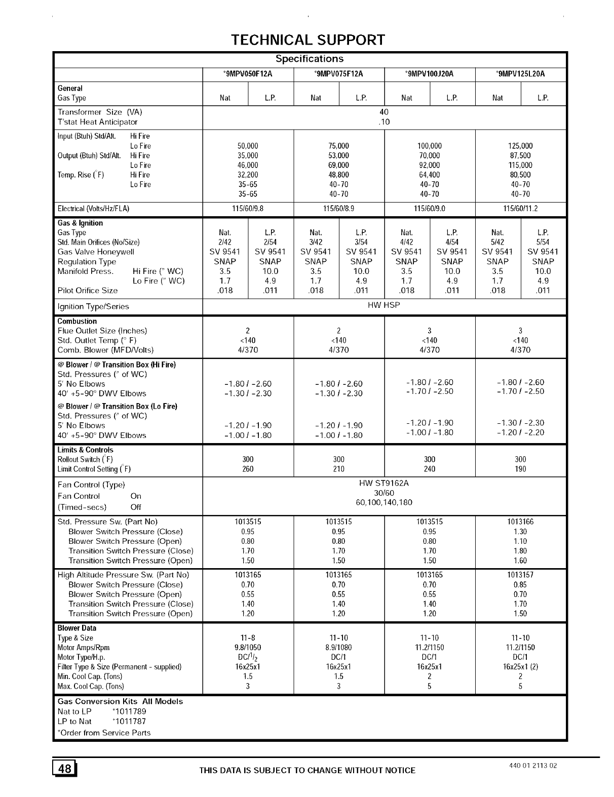
TECHNICAL SUPPORT
Specifications
*gMPVO50F12A _gMPVO75F12A *9MPV100J20A *9MPV125L20A
General
GasType Nat L.P. Nat LP. Nat L.P. Nat L.P.
Transformer Size (VA) 40
T'stat Heat Anticipator .10
Input(Btuh)Std/Ait. Hi Fire
Lo Fire 50,000 125,000
Output(Btuh)Std/AIt. HiFire 35,000 87,500
Lo Fire 46,000 115,000
Temp.Rise (F) Hi Fire 32,200 80,500
Lo Fire 35-65 40-70
35-65 40-70
115/60/9.8 115/60/11.2
Electrical(Volts/Hz/FLA)
Gas &Ignition
GasType
Std.MainOrifices(No/Size)
Gas Valve Honeywell
Regulation Type
Manifold Press. Hi Fire (" WC)
Lo Fire (" WC)
Pilot Orifice Size
Ignition TypelSeries
Combustion
Flue Outlet Size (Inches)
Std. Outlet Temp (o F)
Comb. Blower (MFDIVolts)
@Blower I @Transition Box (Hi Fire)
Std. Pressures (" of WC)
5' No Elbows
40' +5-90 ° DWV Elbows
@Blower I @Transition Box (Lo Fire)
Std. Pressures (" of WC)
5' No Elbows
40' +5-90 ° DWV Elbows
Limits & Controls
RoiioutSwitch(F)
LimitControlSetting (F)
Fan Control (Type)
Fan Control On
(Timed-secs) Off
Std. Pressure Sw. (Part No)
Blower Switch Pressure (Close)
Blower Switch Pressure (Open)
Transition Switch Pressure (Close)
Transition Switch Pressure (Open)
High Altitude Pressure Sw. (Part No)
Blower Switch Pressure (Close)
Blower Switch Pressure (Open)
Transition Switch Pressure (Close)
Transition Switch Pressure (Open)
Blower Data
Type & Size
MotorAmpslRpm
MotorTypeIH.p.
FilterType& Size (Permanent- supplied)
Min.CoolCap. (Tons)
Max.Cool Cap. (Tons)
Gas Conversion Kits All Models
Natto LP *1011789
LP to Nat *1011787
*Order from Service Parts
Nat.
2/42
SV 9541
SNAP
3.5
1.7
.O18
75,000
53,000
69,000
48,800
40-70
40-70
115/60/8.9
L.P. Nat.
2/54 3/42
SV 9541 SV 9541
SNAP SNAP
10.O 3.5
4.9 1.7
.Oll .O18
100,000
70,000
92,000
64,400
40-70
40-70
115/6019.0
L.P. Nat.
3/54 4/42
SV 9541 SV 9541
SNAP SNAP
10.O 3.5
4.9 1.7
.Oll .O18
HW HSP
L.P.
4/54
SV 9541
SNAP
10.O
4.9
.Oll
2
<140
41370
-1.80 /-2.60
-1.30 /-2.30
-1.20 /-1.90
-1.00 /-1.80
300
260
1013515
0.95
0.80
1.70
1.50
1013165
0.70
0.55
1.40
1.20
11-8
9.8/1050
DC/1/2
16x25x1
1.5
3
2
<140
4/370
-1.20 /-1.90
-1.00 /-1.80
300
210
1013515
0.95
0.80
1.70
1.50
1013165
0.70
0.55
1.40
1.20
11-10
8.911080
DC/1
16x25x1
1.5
3
3
<140
4/370
-1.80 /-2.60
-1.70/-2.50
-1.20/-1.90
-1 .OO/-1.80
300
240
HW ST9162A
30160
60,1OO,140,180
1013515
0.95
0.80
1.70
1.50
1013165
0.70
0.55
1.40
1.20
11-10
11.2t1150
DC/1
16x25x1
2
5
Nat. L.E
5/42 5/54
SV 9541 SV 9541
SNAP SNAP
3.5 10.0
1.7 4.9
.O18 .Oll
3
<140
4/370
-1.80 /-2.60
-1.70 /-2.50
300
190
1013166
1.30
1.10
1.80
1.60
1013157
0.85
0.70
1.70
1.50
11110
11.2/1150
DC/1
16x25x1(2)
2
5
[_1 THIS DATA IS SUBJECT TO CHANGE WITHOUT NOTICE 440 01 2113 02
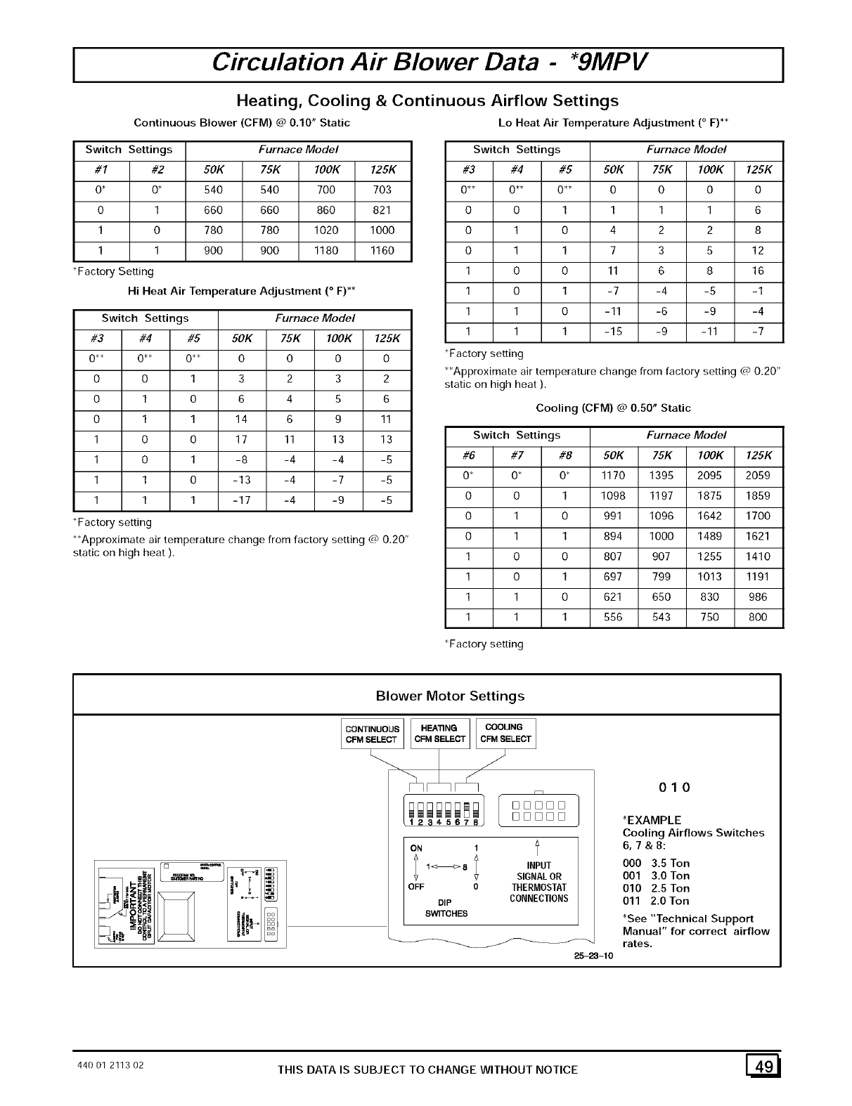
Circulation Air Blower Data - *gMPV
Heating, Cooling & Continuous Airflow Settings
Switch Settings
#1 #2 50K 75K 100K 125K
O* O* 540 540 700 703
0 1 660 660 860 821
1 0 780 780 1020 1000
1 1 900 900 1180 1160
*Factory Setting
Hi Heat Air Temperature Adjustment (° F) **
Switch Settings Furnace Model
Continuous Blower (CFM) @ 0.10" Static Lo
Furnace Model
#3 #4 #5 50K 75K 100K 125K
0"* 0"* 0"* 0 0 0 0
0013232
0106456
0 1 1 14 6 9 11
1 0 0 17 11 13 13
1 0 1 -8 -4 -4 -5
1 1 0 -13 -4 -7 -5
1 1 1 -17 -4 -9 -5
*Factory setting
Heat Air Temperature Adjustment (° F)**
**Approximate air temperature change from factory setting @ 0.20"
static on high heat ).
Switch Settings Furnace Model
#3 #4 #5 50K 75K lOOK 125K
0"* 0"* 0"* 0 0 0 0
0011116
0104228
0 1 1 7 3 5 12
1 0 0 11 6 8 16
1 0 1 -7 -4 -5 -1
1 1 0 -11 -6 -9 -4
1 1 1 -15 -9 -11 -7
*Factory setting
*'Approximate air temperature change from factory setting @ 0.20"
static on high heat ).
Cooling (CFM) @ 0.50" Static
Switch Settings Furnace Model
#6 #7 #8 50K 75K lOOk 125K
O* O* O* 1170 1395 2095 2059
0 0 1 1098 1197 1875 1859
0 1 0 991 1096 1642 1700
0 1 1 894 1000 1489 1621
1 0 0 807 907 1255 1410
1 0 1 697 799 1013 1191
1 1 0 621 650 830 986
1 1 1 556 543 750 800
*Factory setting
Blower Motor Settings
[OONT'"UOOS]I ]1OOO""O]
123456 [1 [1 [1 [1 D
ON 1l
; 1<_>8 ; INPUT
SIGNAL OR
OFF 0 THERMOSTAT
DIP CONNECTIONS
SWITCHES
25-23-10
010
*EXAMPLE
Cooling Airflows Switches
6,7&8:
000 3.5 Ton
001 3.0 Ton
010 2.5 Ton
011 2.0 Ton
*See "Technical Support
Manual" for correct airflow
rates,
44O01 2113O2 THIS DATA IS SUBJECT TO CHANGE WITHOUT NOTICE E_
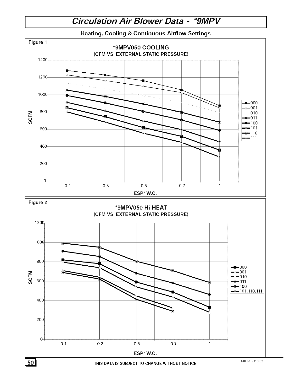
Figure 1
Circulation Air Blower Data - *gMPV
Heating, Cooling & Continuous Airflow Settings
_9MPV050 COOLING
(CFM VS. EXTERNAL STATIC PRESSURE)
O
u_
o
Figure 2
1200
lOOO
800
U.
600
400
200
o
-4--OOO
001
010
_011
--e--lO0
_I01
"m--llO
--'--111
0.1 0.3 0.5 0,7
ESP" W.C.
_9MPV050 Hi HEAT
(CFM VS. EXTERNAL STATIC PRESSURE)
0.1 0.2 0.5 0.7
.-m-ooo
--OOl
----OLO
-_-Oll
-,e-lOO
_1o1,11o,111
ESP" W.C.
THIS DATA IS SUBJECT TO CHANGE WITHOUT NOTICE
[_ 440 01 2113 02
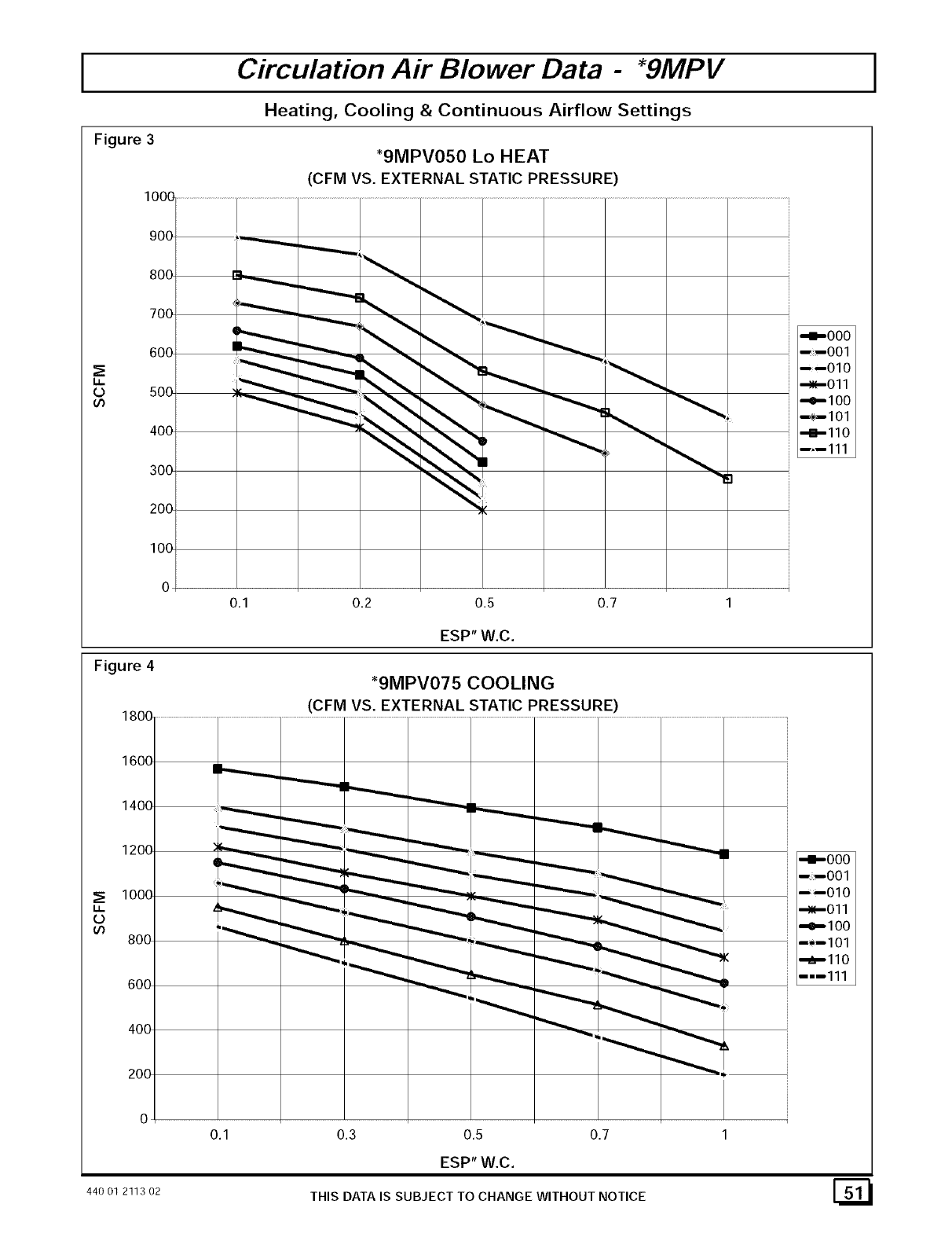
Circulation Air Blower Data - *gMPV
Heating, Cooling & Continuous Airflow Settings
Figure 3 *9MPV050 Lo HEAT
(CFM VS. EXTERNAL STATIC PRESSURE)
1000 .....................................................................................
900 ,_
800 _,...,...__ _.ool
-4-000
600 _-""_'_ _
----010
" ,_--011
0500
"'"'_ _______ _" _ _,,_ _,,__ _' =1100
400 -__! _,_ +110
--,--111
300 :1
2OO
IO0
0
0.1 0.2 0.5 0.7 1
ESP" W.C.
Figure 4
1800 .............................................
1600
1400
1200
_; 1000
W.
o
800
600
400
200
0
)_.._
*9MPV075 COOLING
(CFM VS. EXTERNAL STATIC PRESSURE)
0.1 0.3 0.5 0.7
ESP" W.C.
-i-ooo
--1001
----010
_011
--e--IO0
--_1101
•"m"ll 0
--1--111
44OOl 2113O2 THIS DATA IS SUBJECT TO CHANGE WITHOUT NOTICE [_
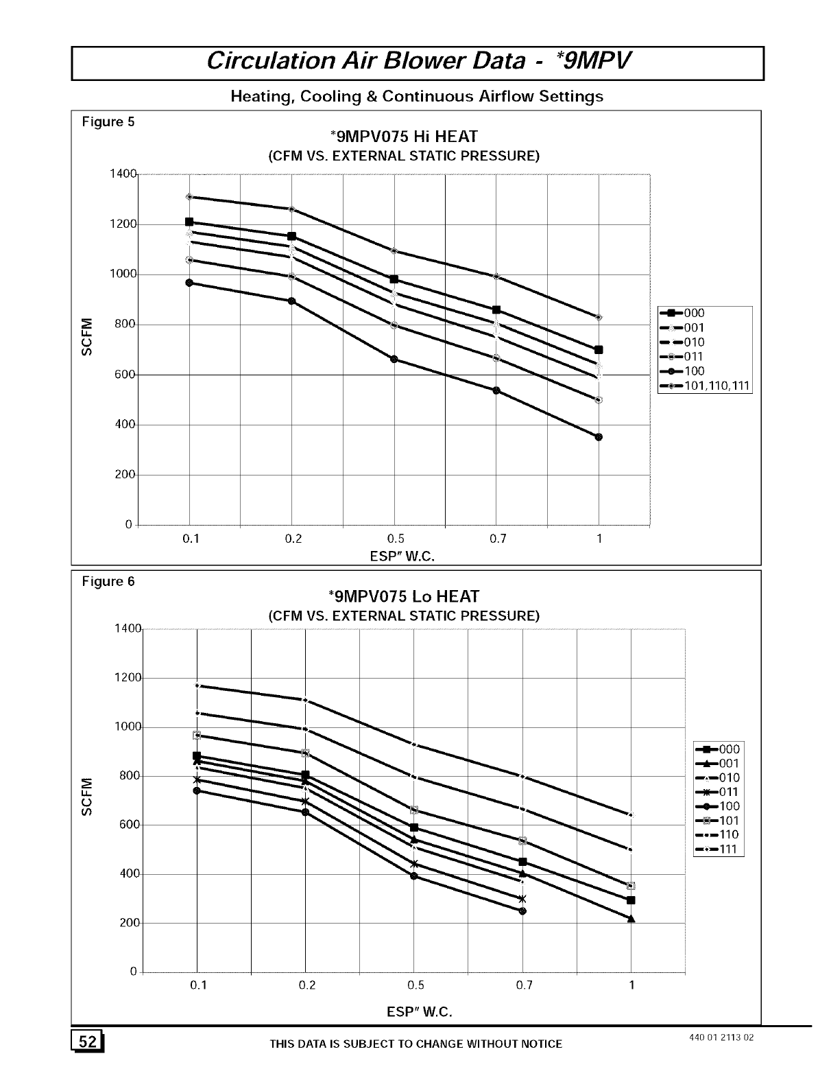
Circulation Air Blower Data - *gMPV
Heating, Cooling & Continuous Airflow Settings
Figure 5
1400
1200
1000
800
u,,,
'0
o')
6OO
_9MPV075 Hi HEAT
(CFM VS. EXTERNAL STATIC PRESSURE)
400
2OO
00.1 0.2 0.5 0.7 1
ESP" W.C.
Figure 6 _9MPV075 Lo HEAT
(CFM VS. EXTERNAL STATIC PRESSURE)
-I-ooo
- -OOl
---OLO
_-Oll
-e-lOO
-_1o1,11o,111
i,
0
oo
o
0.1 0.2 0.5 0.7
ESP" W.C.
THIS DATA IS SUBJECT TO CHANGE WITHOUT NOTICE
"4--OOO
--m--O01
--,1010
_011
--e--IO0
_I01
I-II10
i_--111
[_ 440 01 2113 02
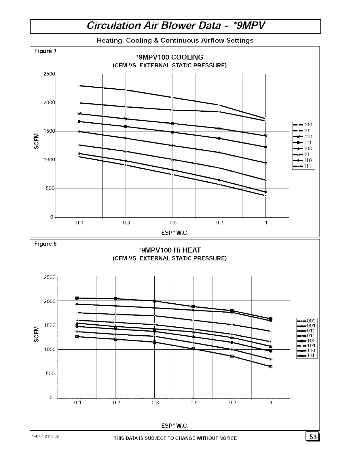
Figure 7
Circulation Air Blower Data - *gMPV
Heating, Cooling & Continuous Airflow Settings
_9MPVIO0 COOLING
(CFM VS. EXTERNAL STATIC PRESSURE)
u.
O
_n
Figure 8
0.1 0.3 0.5 0.7
ESP" W.C.
*9MPVIO0 Hi HEAT
(CFM VS. EXTERNAL STATIC PRESSURE)
I I000
1--001
•_010
i,I--Oll
_I00
-_--I01
_II0
I1--111
i,
0
oo
2500
2000
1500
1000
500
_------_ _=====__
,1
0.1 0,2 0.3 0.5 0.7
ESP" W.C.
THIS DATA IS SUBJECT TO CHANGE WITHOUT NOTICE440 01 2113 02 I_ I
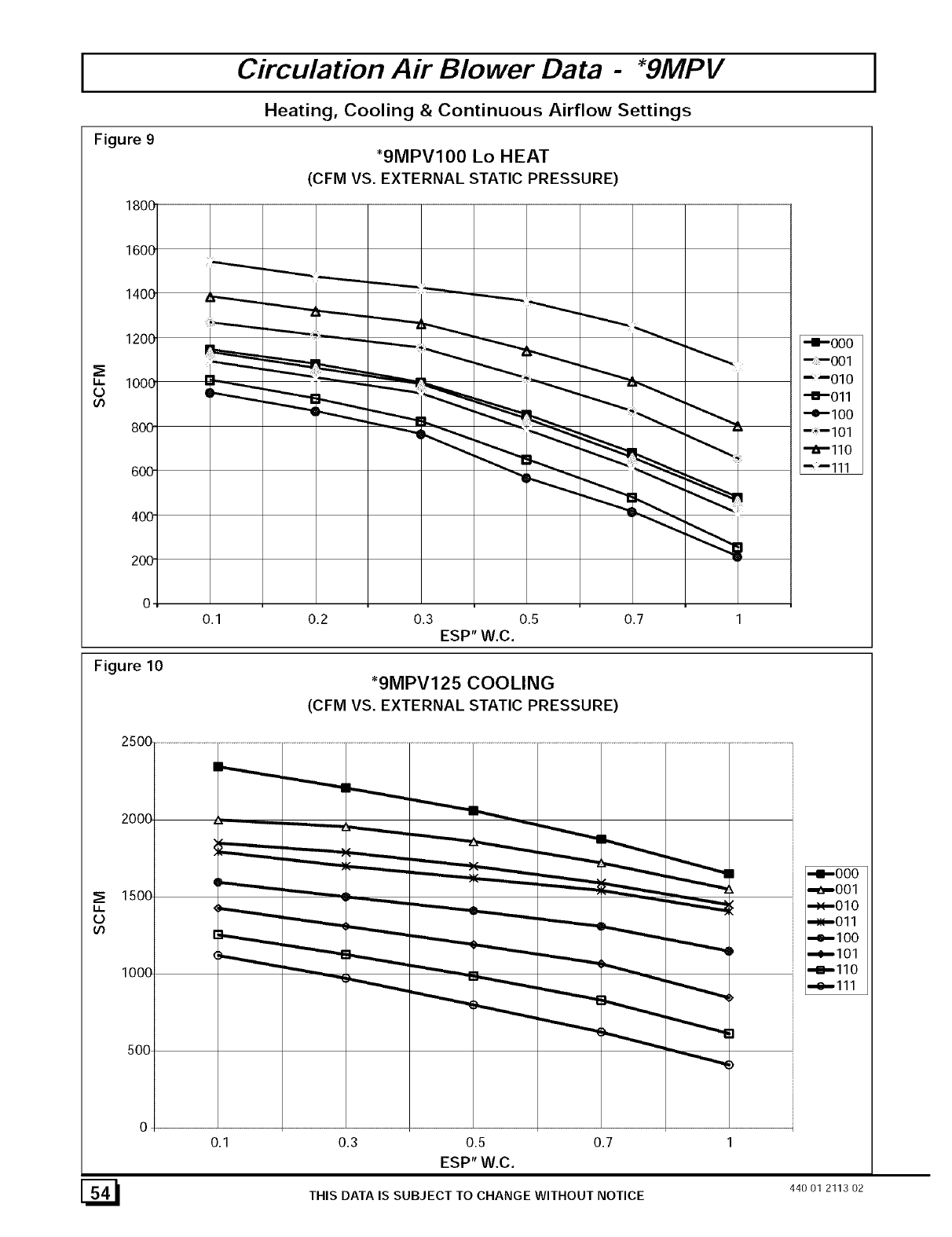
Figure 9
1800
1600
1400
1200
_E
t_ 1000
oo
800
600
400
200
Circulation Air Blower Data -*gMPV
Heating, Cooling & Continuous Airflow Settings
*9MPV100 Lo HEAT
(CFM VS. EXTERNAL STATIC PRESSURE)
-I-OOO
_--001
"--010
-I-Oll
-e-lO0
I 1101
_IIO
--111
0.1 0.2 0.3 0.5 0.7
ESP" W.C.
Figure 10 *9MPV125 COOLING
(CFM VS. EXTERNAL STATIC PRESSURE)
2500 .............................................
!
2000
1500
LL.
O
100o
500
0
0.1
_=._.
-......._ _
0.3 0.5 0.7
ESP" W.C.
-II-000
-t_001
,,_,,-010
,,_011
-4--100
,,_,--101
,,_,-110
,,_-111
[_1 THIS DATA IS SUBJECT TO CHANGE WITHOUT NOTICE 440 Ol 2113 02
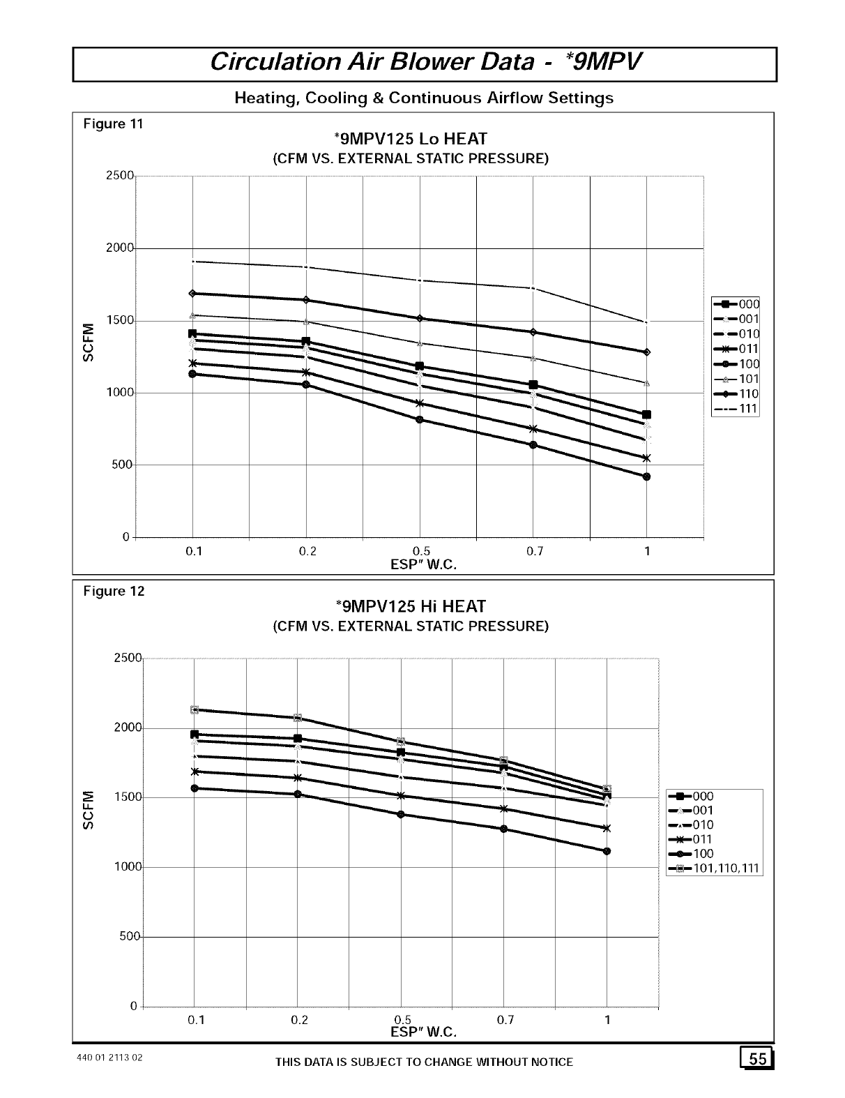
Circulation Air Blower Data - *gMPV
Heating, Cooling & Continuous Airflow Settings
Figure 11
2500
2000
1500
O
lOOO
500
0
Figure 12
*9MPV125 Lo HEAT
(CFM VS. EXTERNAL STATIC PRESSURE)
0.1 0.2 0.5 0.7
ESP" W.C.
*9MPV125 Hi HEAT
(CFM VS. EXTERNAL STATIC PRESSURE)
"4--OOO
O01
----010
"_011
"_--100
_--101
"_'--110
-----111
0
o
"-'-.--
0.1 0.2 0.5 0.7
ESP" W.C.
-m.-ooo
- -OOl
-,-OLO
_Oll
..e-lOO
_1o1,11o,111
44O01 2113O2 THIS DATA IS SUBJECT TO CHANGE WITHOUT NOTICE [_

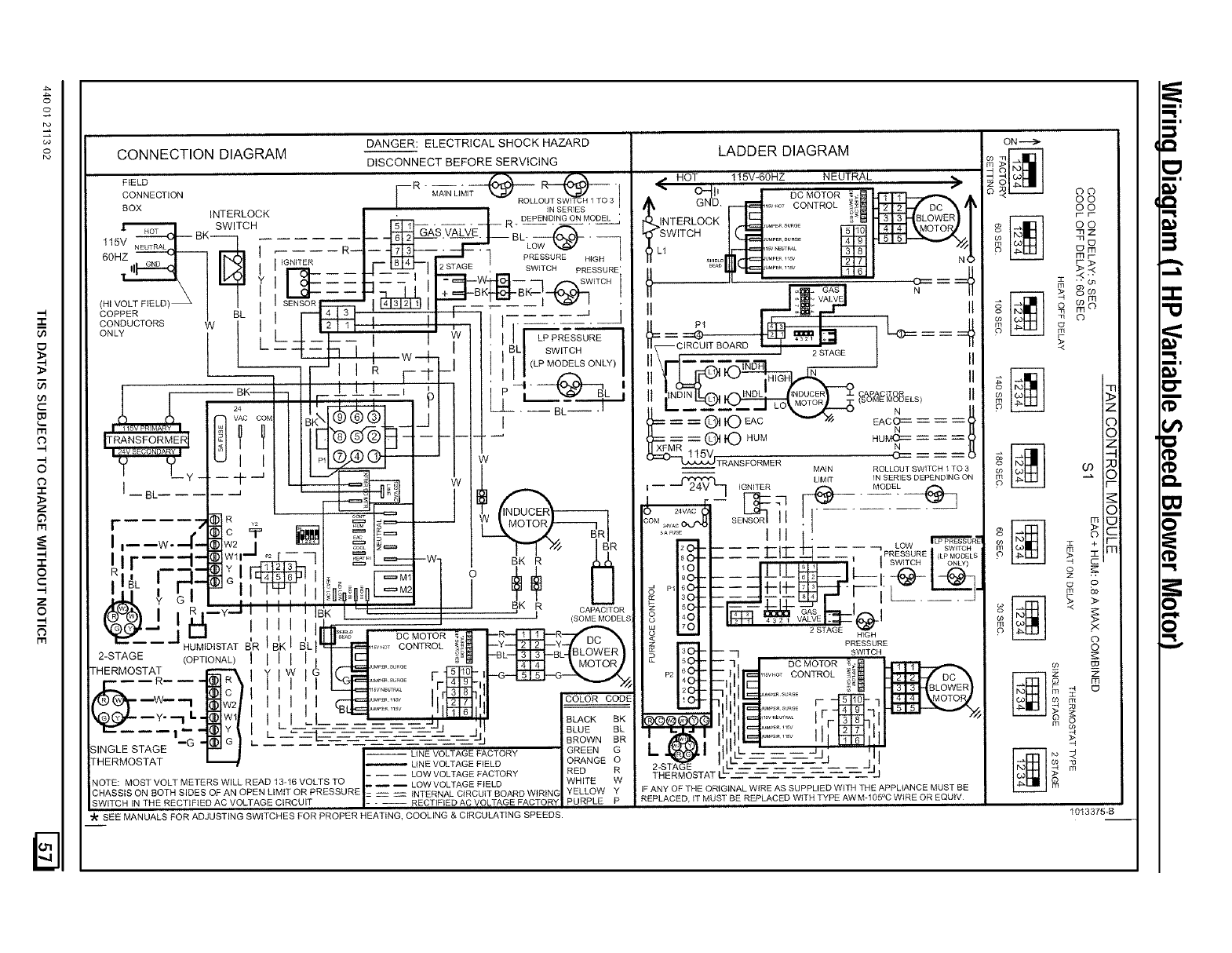
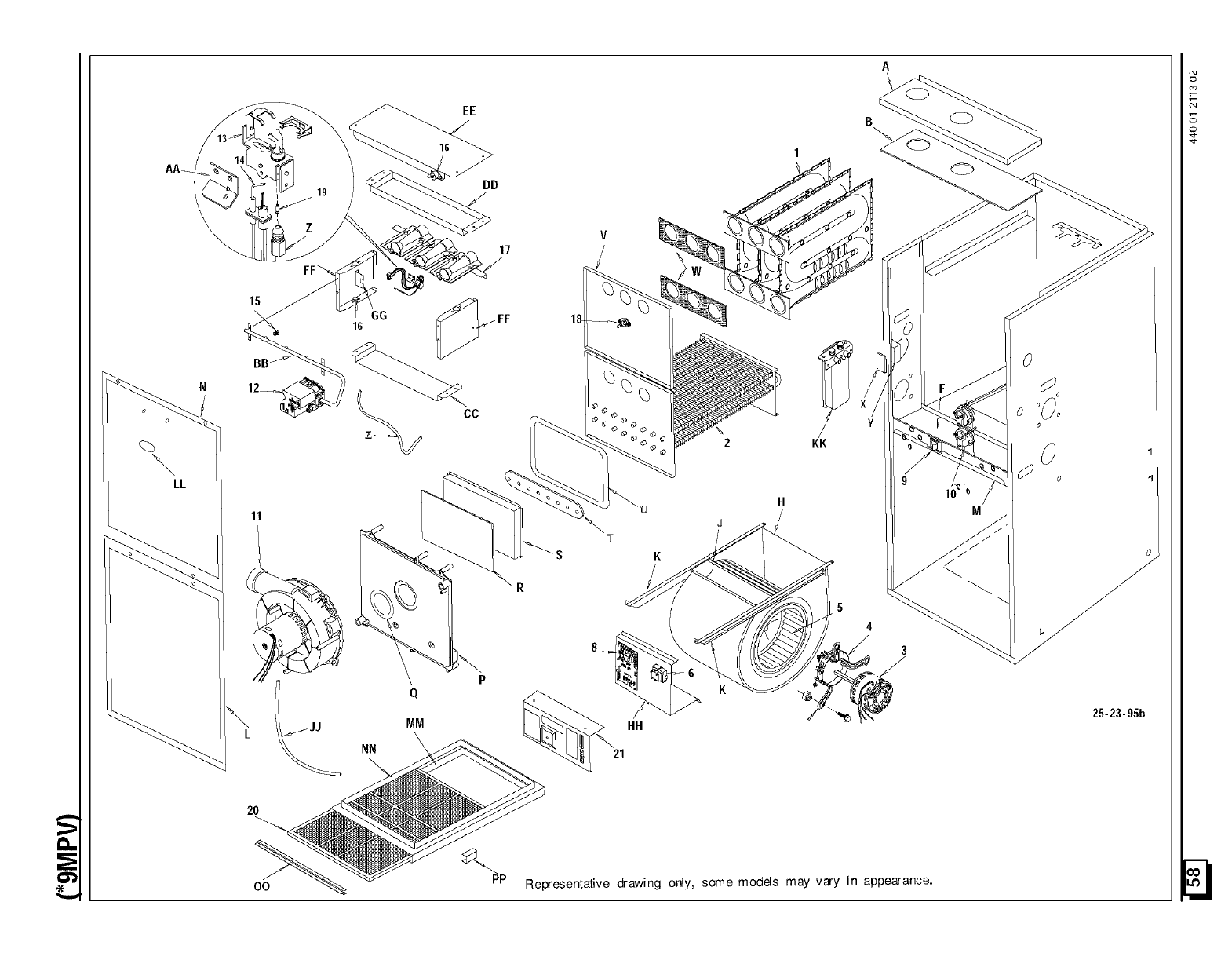
cr_
LL
20
OO
FF'_
GG
16
Q
MM
NN
EE
DD
17
CC
PP
HH
21
H
J
KK
5
4
Representative @awing only, some models may vary in appearance.
10
M
o
o
25-23-95b
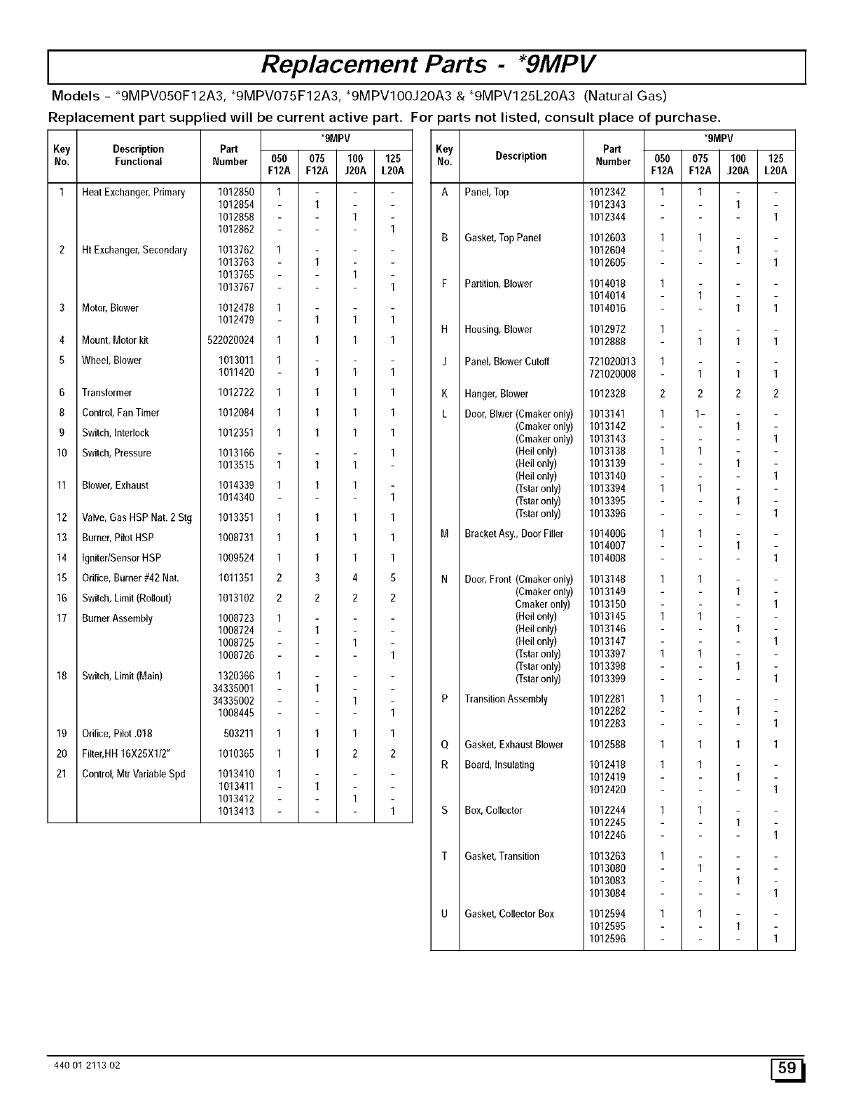
IReplacement Parts -*gMPV
Models - *9MPVO5OF12A3, *9MPVO75F12A3, *9MPVIOOJ2OA3 &*9MPV125L2OA3 (Natural Gas)
Replacement part supplied will be current active part. For
*9MPV
Key Description Part
No. Functional Number 050 075 100 125
F12A F12A J20A L20A
1 Heat Exchanger,Primary
2 Ht Exchanger,Secondary
3 Motor,Blower
4 Mount,Motor kit
5 Wheel, Blower
6 Transformer
8 Control,FanTimer
9 Switch,Interlock
10 Switch,Pressure
11 Blower,Exhaust
12 Valve,Gas HSPNat. 2 Stg
13 Burner,PilotHSP
14 Igniter/SensorHSP
15 Orifice,Burner#42 Nat.
16 Switch,Limit (Rollout)
17 BurnerAssembly
18 Switch,Limit(Main)
19 Orifice,Pilot.018
20 Filter,HH 16X25X1/2"
21 Control,MtrVariableSpd
1012850 1
1012854 1
1012858 1
1012862 1
1013762 1
1013763 1
1013765 1
1013767 1
1012478 1
1012479 1 1 1
522020024 1 1 1 1
1013011 1
1011420 1 1 1
1012722 1 1 1 1
1012084 1 1 1 1
1012351 1 1 1 1
1013166 1
1013515 1 1 1
1014339 1 1 1
1014340 1
1013351 1 1 1 1
1008731 1 1 1 1
1009524 1 1 1 1
1011351 2 3 4 5
1013102 2 2 2 2
1008723 1
1008724 1
1008725 1
1008726 1
1320366 1
34335001 1
34335002 1
1008445 1
503211 1 1 1 1
1010365 1 1 2 2
1013410 1
1013411 1
1013412 1
1013413 1
aarts not listed, consult place of purchase.
*9MPV
Key
No. Description
A Panel,Top
B Gasket,TopPanel
F Partition,Blower
H Housing,Blower
J Panel, Blower Cutoff
K Hanger,Blower
L Door,Blwer (Cmakeronly)
(Croakeronly)
(Cmakeronly)
(Hellonly)
(Hellonly)
(Hellonly)
(]-staronly)
(Tstaronly)
(Tstaronly)
M BracketAsy., DoorFiller
N Door,Front (Cmakeronly)
(Cmakeronly)
Croakeronly)
(Hellonly)
(Hellonly)
(Hellonly)
(Tstaronly)
(Tstaronly)
(]-staronly)
P TransitionAssembly
O Gasket,ExhaustBlower
R Board,Insulating
S Box,Collector
T Gasket,Transition
U Gasket, Collector Box
Part
Number 050 075 100 125
F12A F12A J20A L20A
1012342
1012343
1012344
1012603
1012604
1012605
1014018
1014014
1014016
1 1
1
1
1 1
11
1
1
1 1
1012972 1
1012888 1 1 1
721020013 1
721020008 1 1 1
1012328 2 2 2 2
1013141 1 1-
1013142 1
1013143 1
1013138 1 1
1013139 1
1013140 1
1013394 1 1
1013395 1
1013396 1
1014006 1 1
1014007 1
1014008 1
1013148 1 1
1013149 1
1013150 1
1013145 1 1
1013146 1
1013147 1
1013397 1 1
1013398 1
1013399 1
1012281 1 1
1012282 1
1012283 1
1012588 1 1 1 1
1012418 1 1
1012419 1
1012420 1
1012244
1012245
1012246
111
1
1013263 1
1013080 1
1013083 1
1013084 1
1012594
1012595
1012596
1 1
11
440 01 2113 02 [_
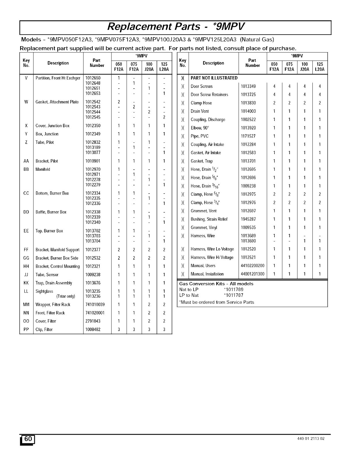
IReplacement Parts - *gMPV
Models - _9MPVO5OF12A3, _9MPVO75F12A3, _9MPVIOOJ2OA3 & _9MPV125L20A3 (Natural Gas)
Replacement part supplied will be current active part. For
*gMPV
Key Part
No. Description Number
V Partition,FrontHtExchger
W Gasket, Attachment Plate
Cover, Junction Box
Box,Junction
Tube, Pilot
X
Y
Z
AA Bracket,Pilot
BB Manifold
CC Bottom,BurnerBox
DD Baffle,Burner Box
EE Top,BurnerBox
FF Bracket,ManifoldSupport
GG Bracket,BurnerBoxSide
HH Bracket,Control Mounting
JJ Tube, Sensor
KK Trap, DrainAssembly
LL Sightglass (Tstaronly)
MM Wrapper,Filter Rack
NN Front,FilterRack
OO Cover,Filter
PP Clip, Filter
1012650
1012648
1012651
1012653
1012542
1012543
1012544
1012545
1012350
1012349
1012832
1013189
1013077
1010901
1012970
1012971
1012278
1012279
1012334
1012335
1012336
1012338
1012339
1012340
1013702
1013703
1013704
1012377
1012532
1012321
1009238
1013676
1013235
1013236
741010039
741020001
2791043
1008482
050 075 100 125
F12A F12A J20A L20A
1
1
1
1
1
2
2
1
1
1
1
1
1
1
1
3
1
1
2
2
1 1
1 1
1
1
1 1
1
1
1
1
1
1
1
1
2 2
2 2
1 1
1 1
1 1
1 1
1 1
1 2
1 2
1 2
3 3
2
1
1
1
1
1
2
2
1
1
1
1
1
2
2
2
3
parts not listed, consult place of purchase.
*gMPV
Key
No,
Elbow,90°
Pipe,PVC
Coupling,Air Intake
Gasket,Air Intake
Gasket,Trap
Hose,Drain 1I2"
Hose,Drain 5/8"
Hose,Drain 3116"
Clamp,Hose5/8"
Clamp,Hose3/4"
Grommet,Vent
Part
Description Number
)( PART NOT ILLUSTRATED
)( DoorScrews 1013349
)( DoorScrew Retainers 1013725
)( ClampHose 1013830
)( Drain Vent 1014003
)( Coupling,Discharge 1002522
)( 1013920
)( 1171527
)( 1012284
)( 1012583
)( 1013701
)( 1012695
)( 1012696
)( 1009238
)( 1012975
)( 1012976
)( 1012697
)( Bushing,StrainRelief 1945287
)( Grommet,Vinyl 1009535
)( Harness,Wire 1013689
1013690
)( Harness,Wire Lo Voltage 1012520
)( Harness,Wire Hi Voltage 1012521
)( Manual, Users 44102200200
)( Manual, Installation 44001201300
Gas Conversion Kits - All models
Nat to LP _1011789
LP to Nat q011787
_Must be ordered from Service Parts
050 075 100 125
F12A F12A J20A L20A
4 4
4 4
2 2
1 1
1 1
1 1
1 1
1 1
1 1
1 1
1 1
1 1
1 1
2 2
2 2
1 1
1 1
1 1
1 1
1 1
1 1
1 1
1 1
4 4
4 4
2 2
1 1
1 1
1 1
1 1
1 1
1 1
1 1
1 1
1 1
1 1
2 2
2 2
1 1
1 1
1 1
1 1
1 1
1 1
1 1
1 1
_[_ 440 O1 2113 02
