ICP Air Handler (indoor Blower&evap) Manual L0502497
User Manual: ICP ICP Air Handler (indoor blower&evap) Manual ICP Air Handler (indoor blower&evap) Owner's Manual, ICP Air Handler (indoor blower&evap) installation guides
Open the PDF directly: View PDF ![]() .
.
Page Count: 14
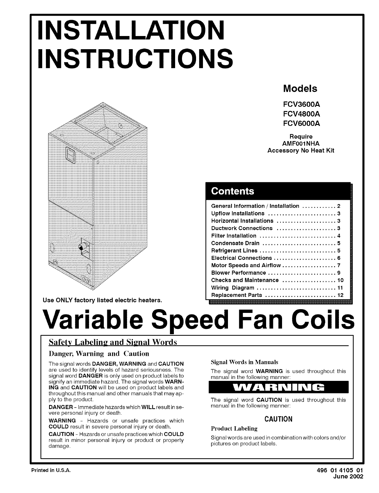
INSTALLATION
INSTRUCTIONS
Models
FCV3600A
FCV4800A
FCV6000A
Require
AMF001NHA
Accessory No Heat Kit
General Information /Installation ............ 2
Upflow Installations ........................ 3
Horizontal Installations ..................... 3
Ductwork Connections ..................... 3
Filter Installation ........................... 4
Condensate Drain .......................... 5
Refrigerant Lines ........................... 5
Electrical Connections ...................... 6
Motor Speeds and Airflow ................... 7
Blower Performance ........................ 9
Checks and Maintenance ................... 10
Wiring Diagram ............................ 11
Replacement Parts ......................... 12
Use ONLY factory listed electric heaters.
Variable Speed Fan Coils
Safety Labeling and Signal Words
Danger, Warning and Caution
The signal words DANGER, WARNING and CAUTION
are used to identify levels of hazard seriousness. The
signal word DANGER is only used on product labels to
signify an immediate hazard. The signal words WARN-
ING and CAUTION will be used on product labels and
throughout this manual and other manuals that may ap-
ply to the product.
DANGER - immediate hazards which WILL result in se-
vere personal injury or death.
WARNING - Hazards or unsafe practices which
COULD result in severe personal injury or death.
CAUTION - Hazards or unsafe practices which COULD
result in minor personal injury or product or property
damage.
Signal Words in Manuals
The signal word WARNING is used throughout this
manual in the following manner:
The signal word CAUTION is used throughout this
manual in the following manner:
CAUTION
Product Labeling
Signal words are used in combination with colors and/or
pictures on product labels.
PrintedinU.S.A. 496 01 4105 01
June 2002
_Installation Instructions
Figure Dimensions and Clearances
Fan Coils I
17-7/8" (3 Ton)
25-1/8" (4 /5 Ton)
Filter Door
8 1/2"
27-1/8 '' (4 /5 Ton)
2"
42"
(3 Ton)
52"
(4-5 Ton)
21 _/2"
38-20-17
CLEARANCES
NO HEATERS
All Sides .................................. 0"
From Supply Duct .......................... 0"
Recommended Service From Front .......... 20"
(Service for blower, filter if installed)
WITH HEATERS
All Sides .................................. 0"
From First Three
Feet of Supply Duct to Combustibles ........ 1"
From Duct after Three Feet ................. 0"
Recommended Service From Front .......... 20"
(Service for blower, filter, heaters if installed)
Fire Hazard
When heaters are installed maintain clear-
ances from combustible materials as speci-
fied on unit rating plate. Do not use plastic
lined or combustible flexible ducting within 36
inches of the supply end of the air handler.
Failure to do so can result in fire, property
damage, personal injury and/or death.
General Information
Installation or repairs made by unqualified persons can
result in hazards to you and others. Installation MUST
conform with local building codes and with the
National Electrical Code NFPAT0 current edition.
The information contained in this manual is intended
for use by a qualified service technician familiar with
safety procedures and equipped with the proper tools
and test instruments.
Failure to carefully read and follow all instructions in
this manual can result in equipment malfunction,
property damage, personal injury and/or death.
The blower cabinet may be used for cooling or heat pump opera-
tion with or without electric heat. Installations without electric
heat, require a No Heat Kit.The cabinet can be installed in an up-
flow or horizontal position (Figure 2, 3). Horizontal installations
require a horizontal kit. Some models are shipped with the hori-
zontal kit already installed .These units are not shipped with air fil-
ters installed. Filter must be field supplied, either washable or
disposal type. Washable filters are available as an accessory.
Location
Select the best position which suits the installation site conditions.
The location should provide adequate structural support, space in
the front of the unit for service access, clearance for return air and
supply duct connections, space for refrigerant piping connections
and condensate drain line connections. If heaters are being
installed make sure adequate clearance is maintained from sup-
ply ductwork, See Clearances and Warning in Figure 1.
NOTE: internal filter can be accessed from separate filter door. if
the filter can NOT be easily accessed, a remote filter is recom-
mended. Refer to ACCA Manual D for remote filter sizing.
If the unit is located in an area of high humidity, nuisance sweating
of casing may occur. On these installations a wrap of 2" fiberglass
insulation with a vapor barrier should be used.
IJJ
I Fan Coils
Upflow Installations
The unit is ready to install in the upflow position without modifica-
tions.
The unit MUST be supported on the bottom ONLY and set on a
supporting frame or shelf. Use screws through the bottom to an-
chor to supporting frame.
Figule 2 lAirflow Positions
UPFLOW POSITION
HEARER
onLTER 38--20--19
Non-Ducted Return Air Closet Installation
The cabinet can be installed in a closet with a false bottom to form
a return air plenum, or mounted on an open platform inside the
closet. Platform should be high enough to provide a free (open)
area for adequate return airflow into the bottom of the cabinet.
The open area can be on the front side or a combination of front
and sides, providing there is clearance on the sides between cabi-
net and closet. Refer to ACCA Manual D for sizing and free
area recommendations.
NOTE: Local codes may limit application of systems without a
ducted return to single story dwellings.
Horizontal Left and Right Installations
Units that are shipped with the horizontal drain pan installed are
set up for horizontal left hand airflow. They must have the drain
pan repositioned for right hand airflow. All other units must have
the horizontal drain pan kit installed for either left or right hand ap-
plications. For installation of the drain pan, refer to the installation
instructions included with the horizontal drain pan kit, and the fo!-
lowing.
CAUTION
Afield-fabricated auxiliary drain pan, with a seperate drain is
REQUIRED for all installations over a finished living space or
in any area that may be damaged by overflow from the main
drain pan. In some localities, local codes require an auxiliary
drain pan for ANY horizontal installation.
Drain Pan Installation /Conversion for Right Hand Air-
flow
See Figure 4
1. Remove coil access panel and carefully pull Coil/Horizon-
tal Drain Pan Assembly out.
2. Separate horizontal drain pan from coil drain pan. The coil
drain pan fits snuggly inside the horizontal pan.
Installation Instructions I
Figure 3 IAirflowPositions
HORIZONTAL LEFT POSITION
,,=,
HORIZONTAL RIGHT POSITION
,,=,
m
38-20-19
3. Position side of coil drain pan into horizontal drain pan
trough on deep end of pan on right side of coil.
4 Remove coil drip flanges from A-coil and reinstall on right
side of coil (same side as horizontal drain pan).
5. Remove the coil support bracket from the left side of the
cabinet and reinstall bracket on the right side of the cabinet.
6. Install drain plugs as required in back side of horizontal
drain pan. Install plugs in A col! drain pan to prevent air
leaks.
7. Slide coil assembly into cabinet being careful not to tear in-
sulation.
NOTE: Be sure A coil pan fits into the support bracket on the back
side of the cabinet and that pan is under the flange of the bracket
on the right side. The brackets fit over the top edge of the A coil
drain pan to hold it when it's put into the horizontal position.
8. Refer to Restrictor Orifice Selection and change restrictor if
necessary, then install coil access panel.
Cabinet can now be placed on it's side for horizontal airflow.
Suspended Cabinet Installation
1. The cabinet may be supported on a frame or shelf, or it may
be suspended.
2. Use metal strapping or threaded rod with angle iron sup-
ports under the auxiliary drain pan to suspend cabinet.
These supports MUST run parallel with the length of the
cabinet (Figure 5 ).
3. Ensure that there is adequate room to remove service and
access panels after installing supporting brackets.
4. Place Styrofoam blocks in auxiliary drain pan to support
cabinet.
Duct Connections
Supply Duct
Supply duct must be attached to the outside of flange on outlet
end of unit. Flexible connectors may be used if desired. Maintain
clearances from supply duct to combustibles when heaters are
installed. See Figure 1 and unit rating plate.
Return Duct
Return duct should be attached to bottom of unit using sheet met-
al screws or other fasteners.
I Installation Instructions
FigUre 4 Horizontal Drain Pan
Fan Coils I
Drip Flange mounts to
top two holes in coil plate
Coil Access Panel
Horizontal Drain Pan
(Left Hand Airflow) Coil Support Bracket
(Right Hand Airflow)
\
Filter Door
Drip Flanges
(Left Hand Airflow)
Drip Flanges
(Right Hand Airflow)
il Support Bracket
Coil Support Bracket
(Left Hand Airflow)
--_ Plug drains
on back side
Horizontal Drain Pan
(Right Hand Airflow)
38-20-06
Filter Installation
Filters must be field supplied. The blower cabinet is set up for an
internal filter or a remote filter grille or other means may be pro-
vided. Refer to ACCA Manual D for remote filter sizing.
To install an internal filter, remove screw securing filter door and
slide filter into unit. Some filters are marked for airflow direction,
make sure arrow points towards blower if marked. Washable fil-
ters are offered as an accessory. Disposable filter sizes are listed
in Filter Static Pressure Drop Table.
Figure 5 Horizontal Installation
l Field-Fabricated
Drain Pan
Supports MUST run parallel with blower cabinet =_-o=
I Fan Coils Installation Instructions
Condensate Drain Connections
The unit is provided with 3/4" National Pipe Thread (NPT) con-
densate drains. (Figure 1). Any drain can be used as a primary or
secondary drain. Condensate drain lines should be installed in a
manner that does not obstruct access to the filter.
There is a secondary drain fitting supplied with the unit that will
convert any of the primary condensate drain connections into a
secondary drain connection. This fitting should be installed in any
of the primary drain connections to convert it to a secondary drain.
1. Connect the drain lines to the appropriate drain fittings. 3/4"
PVC or other type of drain line may be used. The drain line
must not be smaller than the drain fitting.
2. Install a trap in the drain line below the bottom of the drain
pan and pitch the drain lines down from the coil at least I/4"
per foot of run. Horizontal runs over 15 feet long must also
have an anti-siphon air vent (stand pipe), installed ahead
of the horizontal run. An extremely long horizontal run may
require an oversized drain line to eliminate air trapping.
3. Routetotheoutsideortoafloordrain, laundrytrayorwaste
line (sewer). Check local codes before connecting to a
sewer line.
4. Insulate drain lines where sweating could cause water
damage.
5. If a gravity drain cannot be used, install a condensate
pump. Install the pump as close to the indoor section as
possible.
Waste Line Connection
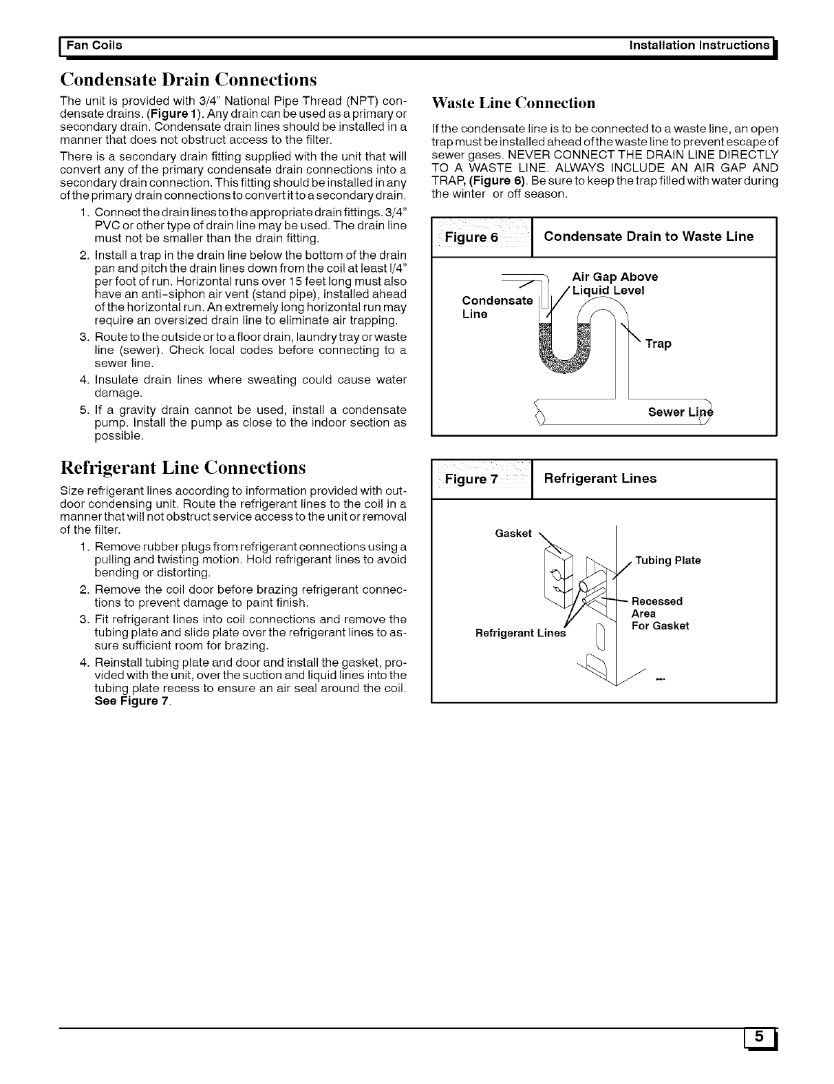
If the condensate line is to be connected to a waste line, an open
trap must be installed ahead of the waste line to prevent escape of
sewer gases. NEVER CONNECT THE DRAIN LINE DIRECTLY
TO A WASTE LINE. ALWAYS INCLUDE AN AIR GAP AND
TRAP, (Figure 6). Be sure to keep the trap filled with water during
the winter or off season.
Figure 6 I Condensate Drain to Waste Line
Air Gap Above
uid Level
Condensate
Line
Sewer Li_
Refrigerant Line Connections
Size refrigerant lines according to information provided with out-
door condensing unit. Route the refrigerant lines to the coil in a
manner that wil! not obstruct service access to the unit or removal
of the filter.
1. Remove rubber plugs from refrigerant connections using a
pulling and twisting motion. Hold refrigerant lines to avoid
bending or distorting.
2. Remove the coil door before brazing refrigerant connec-
tions to prevent damage to paint finish.
3. Fit refrigerant lines into coi! connections and remove the
tubing plate and slide plate over the refrigerant lines to as-
sure sufficient room for brazing.
4. Reinstall tubing plate and door and install the gasket, pro-
vided with the unit, over the suction and liquid lines into the
tubing plate recess to ensure an air seal around the coil.
See Figure 7.
Figule 7 Refrigerant Lines
Gasket __
Refrigerant Lines _]
jTubing Plate
Recessed
Area
For Gasket
_Installation Instructions
Electrical Connections
Electrical shock hazard.
Turn OFF electric power at fuse box or service
panel before making any electrical connections
and ensure a proper ground connection is made
before connecting line voltage.
Failure to do so can result in property damage,
personal injury and/or death.
All electrical work MUST conform with the requirements of local
codes and ordinances and the National Electrical Code NFPA 70
current edition.
The low voltage transformer and the fan control are standard on
all models and are prewired at the factory. Line voltage
connections are made to the heater accessory or the lugs on the
No Heat Kit.
Overcurrent Protection
The power supply wiring to the unit MUST be provided with
overcurrent protection. Governing codes may require this to be
fuses ONLY or circuit breakers.
For blower cabinets without heaters, a 15 amp circuit may be
used.
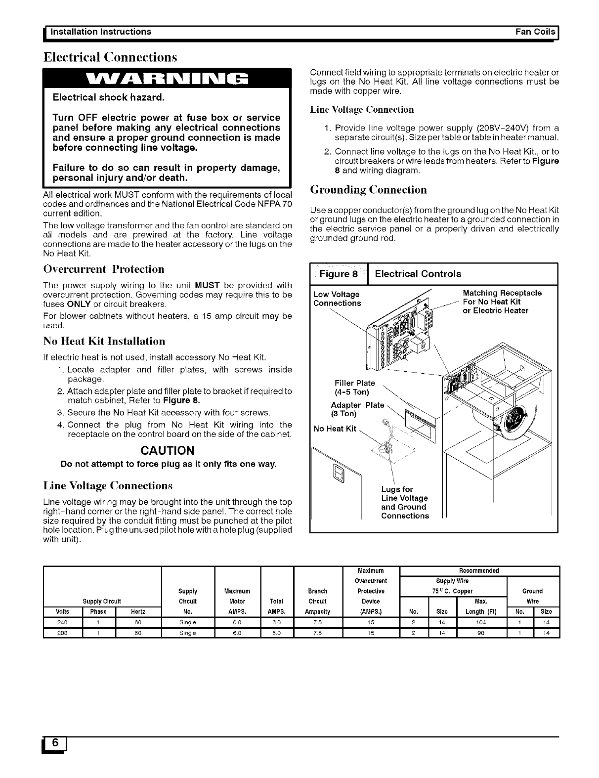
No Heat Kit Installation
If electric heat is not used, install accessory No Heat Kit.
1. Locate adapter and filler plates, with screws inside
package.
2. Attach adapter plate and filler plate to bracket if required to
match cabinet, Refer to Figure 8.
3. Secure the No Heat Kit accessory with four screws.
4. Connect the plug from No Heat Kit wiring into the
receptacle on the control board on the side of the cabinet.
CAUTION
Do not attempt to force plug as it only fits one way.
Line Voltage Connections
Line voltage wiring may be brought into the unit through the top
right-hand corner or the right-hand side panel. The correct hole
size required by the conduit fitting must be punched at the pilot
hole location. Plug the un used pilot hole with a hole plug (supplied
with unit).
Fan Coils [
Connect field wiring to appropriate terminals on electric heater or
lugs on the No Heat Kit. All line voltage connections must be
made with copper wire.
Line Voltage Connection
1. Provide line voltage power supply (208V-240V) from a
separate circuit(s). Size per table or table in heater manual.
2. Connect line voltage to the lugs on the No Heat Kit., or to
circuit breakers or wire leads from heaters. Refer to Figure
8 and wiring diagram.
Grounding Connection
Use a copper conductor(s) from the ground lug on the No Heat Kit
or ground lugs on the electric heater to a grounded connection in
the electric service panel or a properly driven and electrically
grounded ground rod.
Figure81 Electrical Controls
Low Vol!age _Matching Receptacle
Connections ._e_ _For No Heat Kit
or Electric Heater
Filler Plate
(4-5 Ton)
Adapter Plate _
(3 Ton)
.oHeat _:_! ....
Lugs for
Line Voltage
and Ground
Connections
Supply Circuit
Volts Phase Hertz
240 1 60
208 1 60
Supply
Circuit
N0,
Single
Single
Maximum Branch
Motor Total Circuit
AMP8. AMP8. Ampacity
60 60 75
60 60 75
Maximum
Overcurrent
Protective
Device
(AMP8.)
15
15
Recommended
SupplyWire
75o C. Copper
Max,
No, Size Length (Ft)
2 14 104
2 14 90
Ground
Wire
No. Size
1 14
1 14
LtJ
I Fan Coils
Low Voltage Control Connections
The 24 volt power supply is provided by an internally wired low
voltage transformer which is standard on all models. If power
supply is 208 volt, the low voltage transformer must be rewired to
the 208 volt tap. See the unit wiring label.
Field supplied low voltage wiring can enter the unit on the top left
hand corner* or the left hand side panel. When using the left hand
side panel entrance, the low voltage wiring must be fed through
the entrance hole in the bottom of the blower deck into the control
area.
Install the strain relief bushing (supplied with unit) in the selected
hole and a hole plug (supplied with unit) in the unused hole.
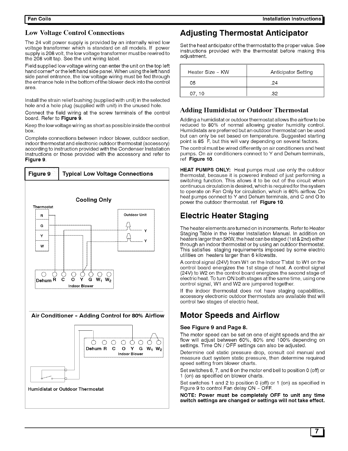
Connect the field wiring at the screw terminals of the control
board. Refer to Figure 9.
Keep the low voltage wiring as short as possible inside the control
box.
Complete connections between indoor blower, outdoor section,
indoor thermostat and electronic outdoor thermostat (accessory)
according to instruction provided with the Condenser Installation
Instructions or those provided with the accessory and refer to
Figure 9.
Figure 9 [ Typical Low Voltage Connections
Cooling Only
Thermostat
R--
G
Y
W
O () () 0 () 0 0 0
Dehum R C O YGW 1 W 2
Indoor Blower
Outdoor Unit
Y
__y
Air Conditioner -Adding Control for 80% Airflow
IDe.Oum°
Humidistat or Outdoor Thermostat
0 0 _ 0 _/_)w2
CO Y G
IndoorBlower
Installation Instructions I
Adjusting Thermostat Anticipator
Set the heat anticipator of the thermostat to the proper value. See
instructions provided with the thermostat before making this
adjustment.
Heater Size - KW Anticipator Setting
05 .24
07, 10 .32
Adding Humidistat or Outdoor Thermostat
Adding a humidistat or outdoor thermostat allows the airflow to be
reduced to 80% of normal allowing greater humidity control.
Humidistats are preferred but an outdoor thermostat can be used
but can only be set based on temperature. Suggested starting
point is 85 F, but this will vary depending on several factors.
The control must be wired differently on air conditioners and heat
pumps. On air conditioners connect to Y and Dehum terminals,
ref Figure 10.
HEAT PUMPS ONLY: Heat pumps must use only the outdoor
thermostat, because it is powered instead of just performing a
switching function. This allows it to be out of the circuit when
continuous circulation is desired, which is required for the system
to operate on Fan Only for circulation, which is 60% airflow. On
heat pumps connect to Y and Dehum terminals, and C and O to
power the outdoor thermostat, ref Figure 10.
Electric Heater Staging
The heater elements are turned on in increments. Refer to Heater
Staging Table in the Heater Installation Manual. In addition on
heaters larger than 5KW, the heat can be staged (1 st & 2nd) either
through an indoor thermostat or by using an outdoor thermostat.
This satisfies staging requirements imposed by some electric
utilities on heaters larger than 6 kilowatts.
A control signal (24V) from Wl on the Indoor T'stat to Wl on the
control board energizes the 1st stage of heat. A control signal
(24V) to W2 on the control board energizes the second stage of
electric heat. To turn ON both stages atthe same time, using one
control signal, W1 and W2 are jumpered together.
If the indoor thermostat does not have staging capabilities,
accessory electronic outdoor thermostats are available that will
control two stages of electric heat.
Motor Speeds and Airflow
See Figure g and Page 8.
The motor speed can be set on one of eight speeds and the air
flow will adjust between 60%, 80% and 100% depending on
settings. Time ON /OFF settings can also be adjusted.
Determine coil static pressure drop, consult coil manual and
measure duct system static pressure, then determine required
speed setting from blower charts.
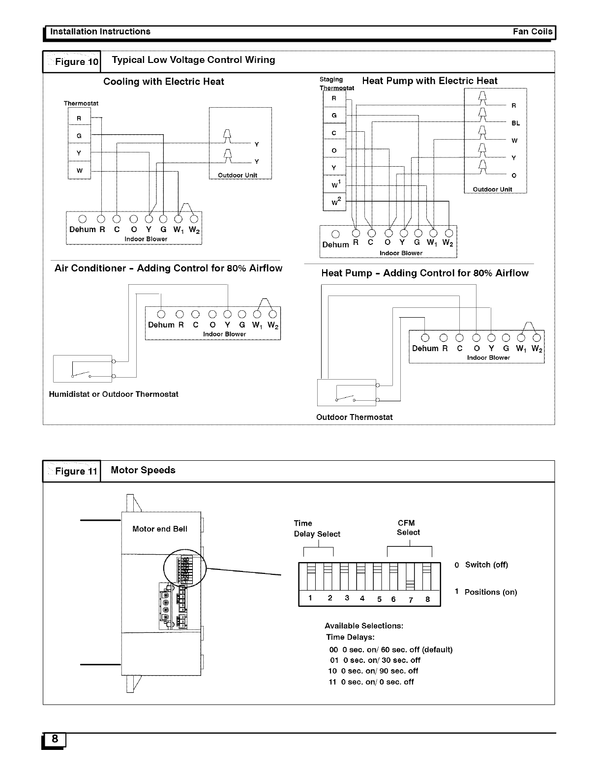
Set switches 6, 7, and 8 on the motor end bell to position 0 (off) or
1 (on) as specified on blower charts.
Set switches 1 and 2 to position 0 (off) or 1 (on) as specified in
Figure 9 to control Fan delay ON - OFR
NOTE: Power must be completely OFF to unit any time
switch settings are changed or settings will not take effect.
_Installation Instructions
Figure 10[ Typical Low Voltage Control Wiring
Cooling with Electric Heat
Thermostat
BY
Outdoor Unit
o2J I or o
Air Conditioner -Adding Control for 80% Airflow
Fan CoilsI
Staging Heat Pump with Electric Heat
I
© ©
Dehum R C O Y G
IndoorBlower
_eJ331o3 tat
R
G
w 1
w2
0 Y G W.
Indoor Blower
Outdoor Unit
BL
W
-- y
O
Heat Pump -Adding Control for 80% Airflow
mC O Y G
IndoorBlower
Humidistat or Outdoor Thermostat
Outdoor Thermostat
Figure 1i [Motor Speeds
Motor end Bell
U/
_-'--------__._..._.._
J
Time
Delay Select
CFM
Select
I
I I
1 2 3 4 5 6 7 8
Available Selections:
Time Delays:
00 0 sec. on/60 sec. off (default)
01 0 sec, on/30 sec, off
10 0 sec, on/90 sec. off
11 0 sec. on/0 sec. off
0 Switch (off)
1 Positions (on)
I Fan Coils Installation Instructions
LL
0
1600 •
1400,
1200"
1000,
800,
600,
400 •
200
0.1
FCV36
IIIIIII
IIIIIII
IIIIIII
IIIIIII
0.2 0.3 0.4 0.5 0.6 0.7 0.8
External Static
0.9
LI.
0
U_
2200_
2000,
1800,
1600,
1400,
1200,
1000,
800,
600,
400
0.!
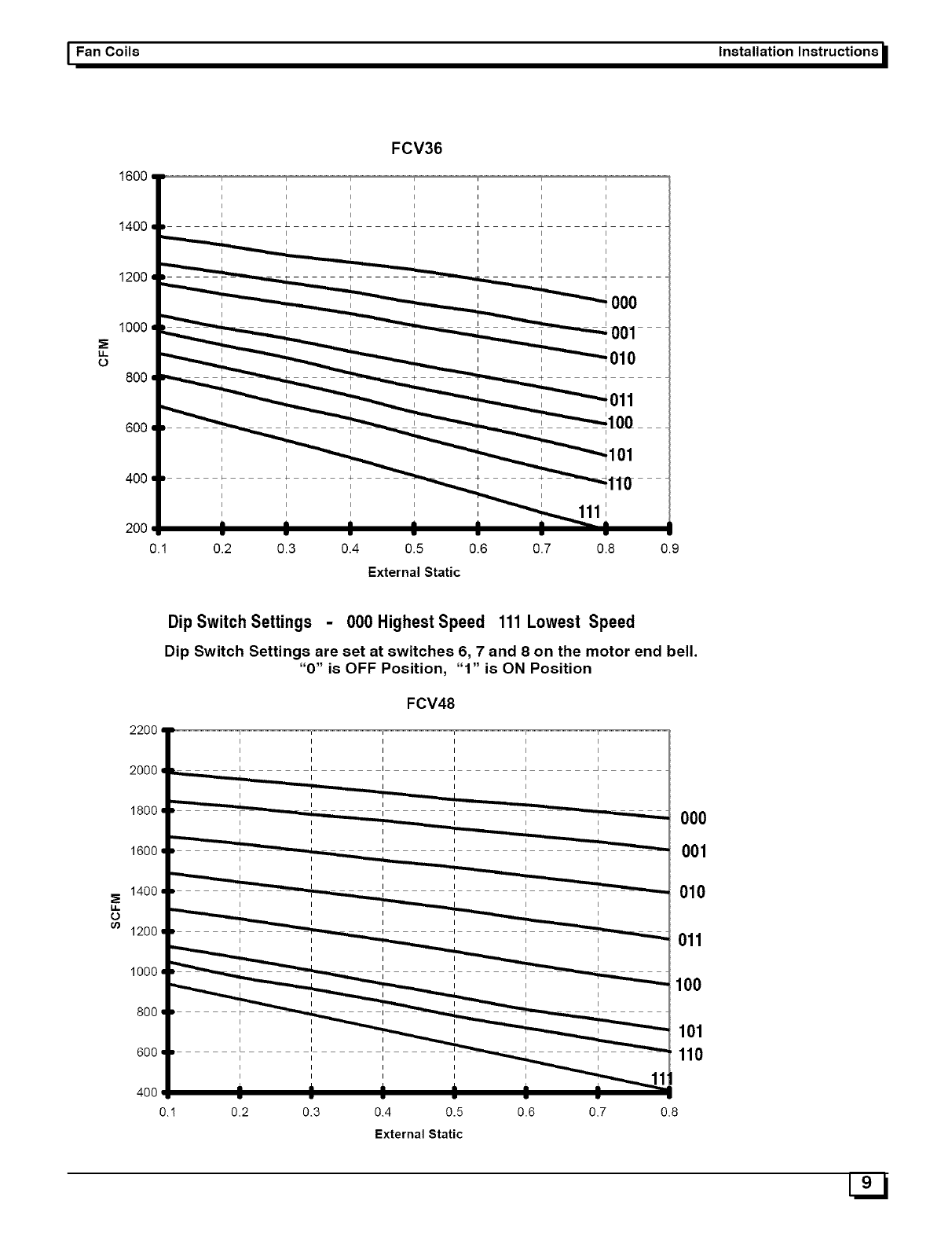
Dip Switch Settings -000 Highest Speed 111Lowest Speed
Dip Switch Settings are set at switches 6, 7 and 8 on the motor end bell.
"0" is OFF Position, "1" is ON Position
FCV48
w
0.2 0.3 0.4 0.5 0.6 0.7
External Static
000
001
010
011
100
101
110
08
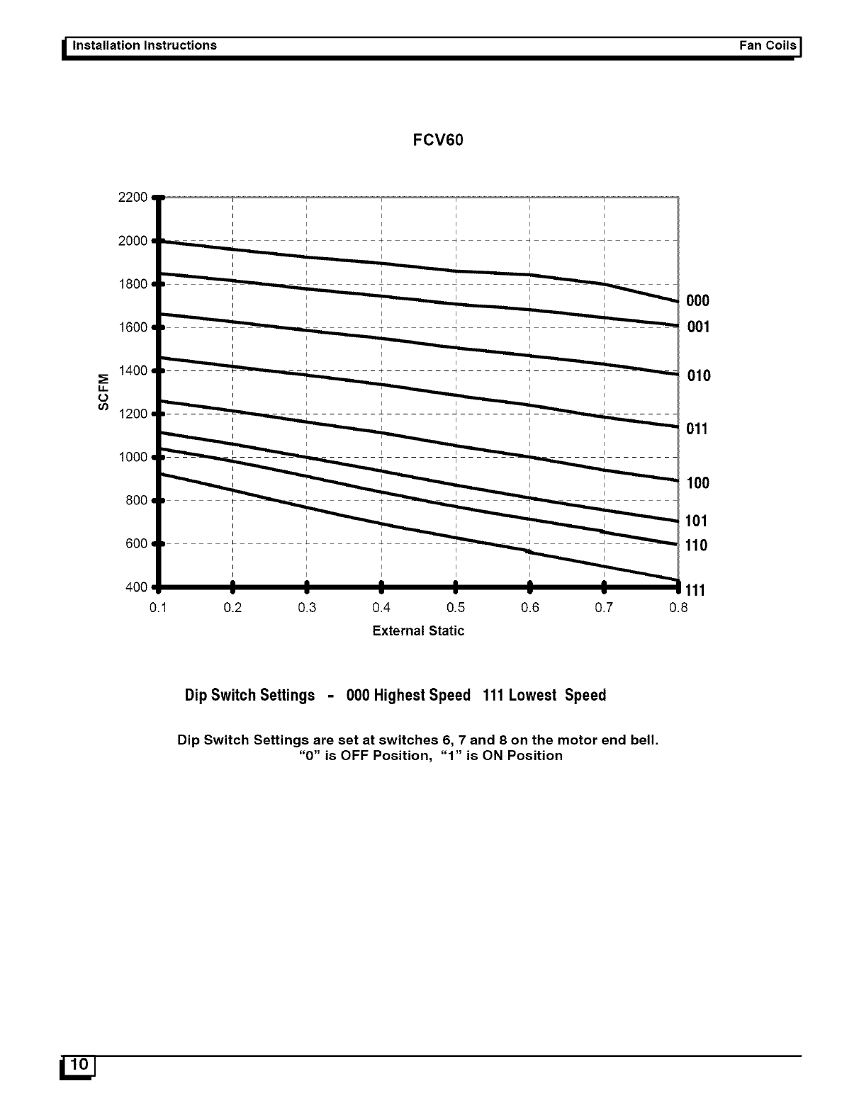
_Installation Instructions Fan Coils ]
FCV60
LL
0
u)
22OO
2000
1800
1600
1400
1200
1000
8OO
6OO
400
0.1
I I I I I
I I I I I
I I I I I
I I I I I
k4 4 _ 4
0.2 0.3 0.4 0.5 0.6 0.7
External Static
000
001
010
011
100
101
110
111
0.8
Dip Switch Settings -000 HighestSpeed 111 Lowest Speed
Dip Switch Settings are set at switches 6, 7 and 8 on the motor end bell.
"0" is OFF Position, "1" is ON Position
I Fan Coils Installation Instructions
MODEL
FCV36
FCV48/FCV60
FILTER STATIC PRESSURE DROP*
*WASHABLE
FINER SIZE DISPOSABLE
FI_ERSIZE 600 800 1000 1400 1600 1800 2000
17 3/4X20 1/4 18X20 ....... 0.09 0.17 0.22 ......
24 3/4 X 20 1/4 25X20 .......... 0.09 0.11 0.14 0.18
CFM
1200
0.12
Air Flow Check
For proper system operation, the air flow through the indoor coil
should be between 350 and 450 cfm per ton of cooling capacity.
The air flow through the unit can be determined by measuring the
external static pressure to the unit and selecting the motor speed
tap that will most closely provide the required air flow.
1. Set up to measure external static pressure at the supply
and return duct connections (Figure12).
2. Drill holes in the ducts for pressure taps, pitot tubes, or
other accurate pressure sensing devices.
Figure '2 lStatic Pressure Check
SupplYr__
e Oon
3. Connect these taps to a level inclined manometer or draft
gauge.
4. Ensure the coil and filter are clean, and all the registers are
open.
5. Determine the external static pressure with the blower
operating.
6. Refer to the Air Flow Data tables, page 8 to find the Dip
Switch Speed setting that will most closely provide the
required air flow for the system.
7. Refer to Motor Speeds and Airflow in these instructions if
the speed is to be changed.
8. Recheck the external static pressure with the new setting,
and confirm speed switch selection.
Temperature Rise Check
Temperature rise is the difference between the supply and return
air temperatures.
NOTE; The temperature rise can be adjusted by changing the
heating speed tap at the unit's blower terminal block.
A temperature rise greater than 60 OF (33.3 °C) is not
recommended.
1. To check the temperature rise through the unit, place
thermometers in the supply and return air ducts as close to
the unit as possible.
2. Open ALL registers and duct dampers.
3. Set thermostat Heat-Cool selector to HEAT.
4. Set the thermostat temperature setting as high as it wil! go.
5. Turn electric power ON.
6. Operate unit AT LEAST 5 minutes, then check
temperature rise.
NOTE; The maximum outlet air temperature for all models
is 200 OF (93.3 °C).
7. Set thermostat to normal temperature setting.
8. Turn electric power OFE
9. Be sure to seal all holes in ducts if any were created during
this process.
Maintenance
Filters
Filters must be cleaned when they become dirty. Inspect at least
once per month. The frequency of cleaning depends upon the
hours of operation and the local atmospheric conditions. Clean
filters keep unit efficiency high.
Lubrication
The bearings of the blower motor are permanently lubricated.
Condensate Drains
During the cooling season check the condensate drain lines to be
sure that condensate is flowing from the primary drain but not
from the secondary drain. If condensate ever flows from the
secondary drain the unit should be promptly shut off and the
condensate pan and drains cleaned to insure a free flowing
primary drain.
U 2J
_Installation Instructions Fan Coils I
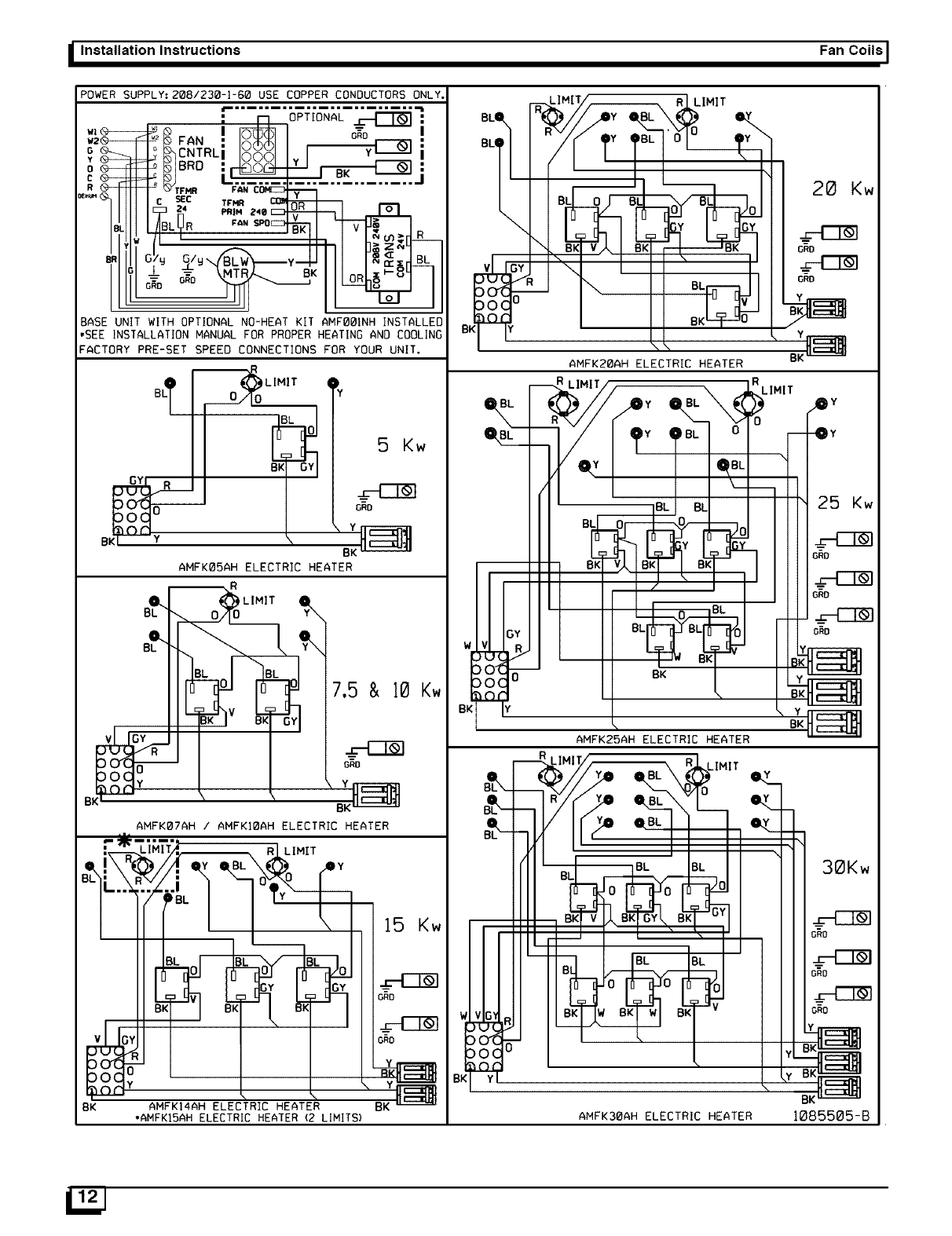
POWER SUPPLY: 208/230-1-60 USE COPPER CONDUCTORS ONLY.
F -_-_;_;t-_
w|_ _ FAN ! _ I o_o
2°_K%CNTRLi IRaqiI
oRo
_'_r__ .............
BASE UNIT WITH OPTIONAL NO-HEAT KIT AMFOOINH INSTALLED
•BEE INSTALLATION MANUAL FOR PROPER HEATING AND COOLING
FACTORY PRE-SET SPEED CONNECTIONS FOR YOUR UNIT.
Y5Kw
AMFKO5AH ELECTRIC HEATER
O..[_)LIMIT
___ _
AMFKO7AH /AMFKIOAH ELECTRIC HEATER
LIMIT
7.5 & 10 Kw
GRO
15 Kw
=-[Z_
ORD
6RO
Y
25 Kw
0 BK
AMFK25AH ELECTRIC HEATER
30Kw
)c)z
)0( C
BK Y
GRO
BK AMFKI4AH ELECTRIC HEATER BK BK
•AMFKI5AH ELECTRIC HEATER (2 LIMITS) AMFK30AH ELECTRIC HEATER 1085505-B
I Fan Coils Installation Instructions
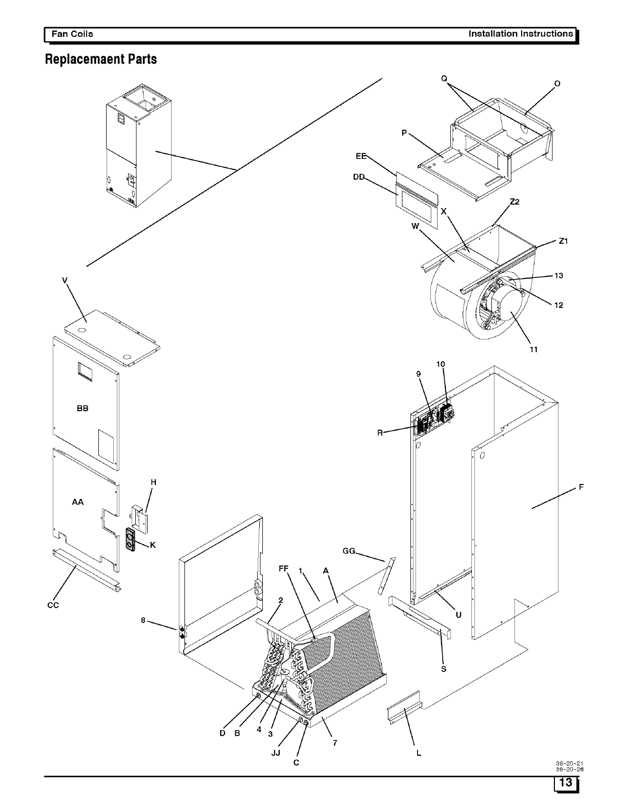
ReplacemaentParts
W
QO
Z2
CC
BB
AA
10
9
A
DB
JJ
11
38-20-21
38-20-26
IInstallation Instructions Fan Coils I
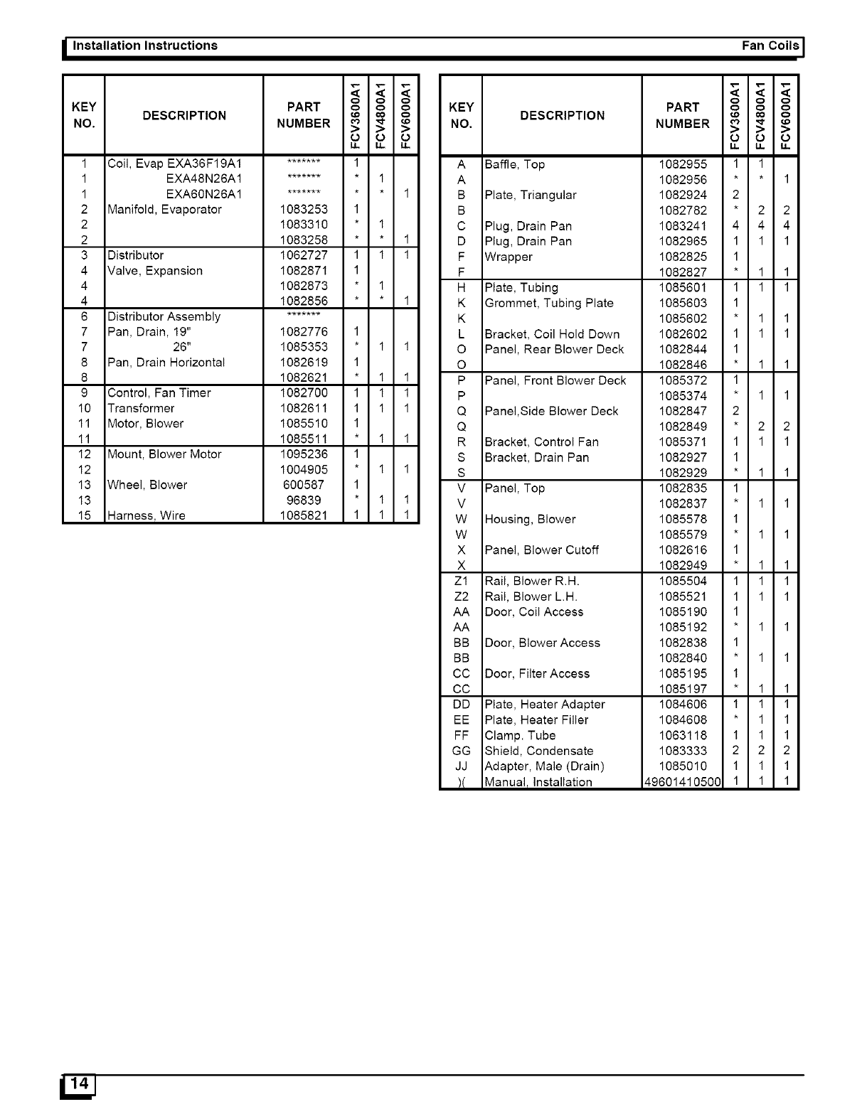
KEY DESCRIPTION
NO.
1 Coil, Evap EXA36F19A1
1 EXA48N26A1
1 EXA60N26A1
2 Manifold, Evaporator
2
2
3 Distributor
4 Valve, Expansion
4
4
6 Distributor Assembly
7 Pan, Drain, 19"
7 26"
8 Pan, Drain Horizontal
8
9 Control, Fan Timer
10 Transformer
11 Motor, Blower
11
12 Mount, Blower Motor
12
13 Wheel, Blower
13
15 Harness, Wire
PART o o o
NUMBER g >=
1083253 1
1083310 * 1
1083258 * * 1
1062727 1 1 1
1082871 1
1082873 * 1
1082856 * * 1
1082776 1
1085353 * 1 1
1082619 1
1082621 * 1 1
1082700 1 1 1
1082611 1 1 1
1085510 1
1085511 * 1 1
1095236 1
1004905 * 1 1
600587 1
96839 * 1 1
1085821 1 1 1
KEY DESCRIPTION
NO,
A Baffle, Top
A
B Plate, Triangular
B
C Plug, Drain Pan
D Plug, Drain Pan
F Wrapper
F
H Plate, Tubing
K Grommet, Tubing Plate
K
L Bracket, Coil Hold Down
O Panel, Rear Blower Deck
O
P Panel, Front Blower Deck
P
Q Panel,Side Blower Deck
Q
R Bracket, Control Fan
S Bracket, Drain Pan
S
V Panel, Top
V
W Housing, Blower
W
X Panel, Blower Cutoff
X
Zl Rail, Blower R.H.
Z2 Rail, Blower LH.
AA Door, Coil Access
AA
BB Door, Blower Access
BB
CC Door, Filter Access
CC
DD Plate, Heater Adapter
EE Plate, Heater Filler
FF Clamp. Tube
GG Shield, Condensate
JJ Adapter, Male (Drain)
)( Manual, Installation
ooo
PART o o o
NUMBER >=
1082955 1 1
1082956 * * 1
1082924 2
1082782 * 2 2
1083241 4 4 4
1082965 1 1 1
1082825 1
1082827 * 1 1
1085601 1 1 1
1085603 1
1085602 * 1 1
1082602 1 1 1
1082844 1
1082846 * 1 1
1085372 1
1085374 * 1 1
1082847 2
1082849 * 2 2
1085371 1 1 1
1082927 1
1082929 * 1 1
1082835 1
1082837 * 1 1
1085578 1
1085579 * 1 1
1082616 1
1082949 * 1 1
1085504 1 1 1
1085521 1 1 1
1085190 1
1085192 * 1 1
1082838 1
1082840 * 1 1
1085195 1
1085197 * 1 1
1084606 1 1 1
1084608 * 1 1
1063118 1 1 1
1083333 2 2 2
1085010 1 1 1
49601410500 1 1 1
