ICP Air Conditioner/heat Pump(outside Unit) Manual L0523208
User Manual: ICP ICP Air conditioner/heat pump(outside unit) Manual ICP Air conditioner/heat pump(outside unit) Owner's Manual, ICP Air conditioner/heat pump(outside unit) installation guides
Open the PDF directly: View PDF ![]() .
.
Page Count: 10
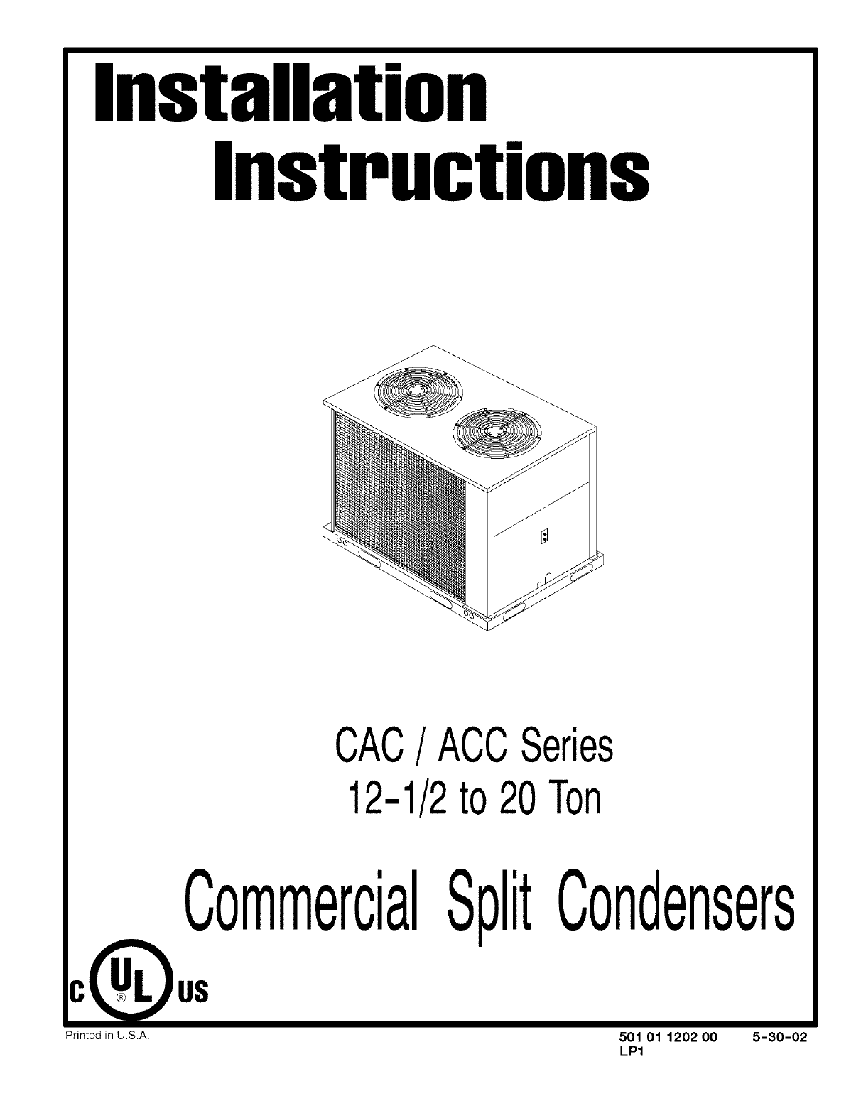
Installation
Instructions
CAC/ACCSeries
12-1/2to20Ton
CommercialSplitCondensers
C_US
Printed in U,S.A. 501 01 1202 O0 5-30-02
LP1
SAFE INSTALLATION REQUIREMENTS
Installation or repairs made by unqualified
persons can result in hazards to you and others.
Installation MUST conform with local building
codes or, in the absence of local codes, with the
the National Electrical Code NFPA 70/ANSI
C1-1993 or current edition and Canadian
Electrical Code Part 1 CSA C.22.1.
The information contained in this manual is
intended for use by a qualified service technician
familiar with safety procedures and equipped
with the proper tools and test instruments.
Failure to carefully read and follow all instruc-
tions in this manual can result in equipment
malfunction, property damage, personal injury
and/or death.
CAUTION: Improper installation, adjustment, alteration,
service or maintenance can void the warranty.
The weight of the condensing unit requires caution and
proper handling procedures when lifting or moving to avoid
personal injury. Use care to avoid contact with sharp or
pointed edges.
Safety Precautions
1. Always wear safety eye wear and work gloves when
installing equipment.
2. Never assume electrical power is disconnected. Check
with meter and disconnect.
3. Keep hands out of fan areas when power is connected
to equipment.
4. R-22 causes frost-bite burns.
5. R-22 is toxic when burned.
NOTE TO INSTALLING DEALER: The Owners
Instructions and Warranty are to be given to the owner or
prominently displayed near the indoor Air Handler Unit.
Before Installation
Inspect the unit for damage before installing. Check the
unit rating plate for correct model number and voltage
requirements of job site before installation.
Foundation Construction
Zoning ordinances may govern the minimum distance
the condensing unit can be installed from the property
line. Check before proceeding.
The remote condensing unit is to be installed on a solid
foundation. This foundation should extend a minimum of 2"
beyond the sides of the condensing unit and must be level.
This foundation can be a precast slab. It can also be a
monolithic poured slab. To eliminate the possibility of noise
transmission, the foundation slab should NOT be in contact
with or be an integral part of the building foundation.
NOTE: At no time should the condensing unit be set on
bricks or concrete blocks.
Condensing Unit Location
These units are designed with "top discharge" condenser
air movement. The condenser air is taken in through the
condenser coil and is discharged out the top.
For quiet operation and maximum efficiency, eliminate any
obstructions which might interfere with air discharge.
After making allowances for zoning ordinances, care
should be exercised not to locate the condensing unit
immediately adjacent to sleeping areas or in corners where
operating noise levels can be amplified. Select a location
as reasonably close to the indoor unit as possible to avoid
any long refrigeration line runs. Place the unit so there is a
minimum of 24" between the building and the service panel
of the unit to allow for service.
Ensure there is a minimum of 12" between the coil inlet and
the building wall, other structure or shrubs.
CAUTION: DO NOT install unit below an overhang that
does not have guttering. A minimum vertical clearance of
60" is required to overhang.
Roof Top Installations
If it is necessary to install units on a roof structure, be sure
to elevate and level the units. Ensure the roof structure and
anchoring method are adequate for unit location. Consult
local codes regarding rooftop mounting.
NOTE: When condensing unit is to be installed on a
bonded guaranteed roof, a release must be obtained from
the building owner to free the installer from all liabilities.
Hoisting
CAUTION
When hoisting unit, at least two slings and two
spreader bars MUST be used to prevent damage to
unit.
NOTE: All access panels MUST be secured in place before
hoisting.
The unit should be hoisted with two lifting slings. Attach the
slings to rigging shackles that have been hooked through
holes in the base rail.
Two spreader bars MUST be placed on top of the unit to
protect the unit from damage from the pressure exerted by
the slings. Make sure that all equipment is adequate to
handle the weight of the unit and that the slings will not al-
low the unit to shift.
Figure 1
Twenty ton unit shown
// Remove 4
screws &
remove panel Mounting Bracket
to access for Unit Disconnect
control box Switch
............ Line
Voltage
........ Low
VoltageWiresWire_,
Service
Valves Low Volt
Terminal
Board
"Low
Voltage
Wires
Suction &
Liquid Line
Connections
'Line
Voltage
Wires
Capacitor
Fan # 1
(12-1/2 &
15 Ton
Only)
0 0
C1
Contactor Anticycle
_Time_
C3 (12 & 15 ton
unitshave2
polecontactor)
Contactor
HHHHHH
C2
Contactor
Capacitor
Fan # 2
(12-1/2 &
15 Ton
Only)
0
Anticycle
Timer
0
Ground
Lug
Control
Box
Transformer
COM
Low Volt
Terminal
Board
LVll
c
G
R
0
YI
Y2
Wl
Terminal w2
Block
Refrigerant Piping
NOTE: All refrigerant piping MUST comply with applicable
local, state and national safety codes. Use only
refrigeration grade copper tubing Type K or L which is
internally clean and damage free.
General NOTES:
Run refrigerant lines should be installed so as to prevent
excessive vibration and strains at joints and connections.
Lines shall be securely fastened to a permanent support
within 6 feet following the first bend from the compressor,
and within 2 feet of each other bend or angle. Lines should
be supported at points not more than 15 feet apart. Lines
should be installed so that it is not subject to damage from
an external source.
Vertical separation of indoor and outdoor sections MUST
NOT exceed 60' (18.3m).
Refrigerant lines MUST NOT exceed the lengths specified
in Figure 2. Contact place of purchase for recommended
procedures if either of the line lengths are too short for a
particular site.
Vertical Suction Risers
It is recommended that vertical suction risers not be
upsized. Proper oil return to the compressor should be
maintained with suction gas velocity. If velocities drop
below 1500 fpm (feet per minute), oil return will be
decreased. An oil trap should be installed every 20' of
vertical suction line riser (condenser above evaporator.)
Refer to line sizing charts.
Line Valves
The outdoor condensing unit is supplied with straight sweat
brass service valves.
All line valves are positioned to seal the refrigerant in the
condensing unit with gauge ports open to connecting lines
when the Schraeder valve is depressed. Gauge ports have
Schraeder installed and require use of charging hoses with
depressors. Do not heat valve body above 250 degrees R
Brazing Connections
Recommended Line Sizes (Max. Equivalent
Figure 2 Feet of Copper Tubing, Type L or K)
Unit Suction Line Size Liquid Line Size
Size (Ton) O.D. Copper O.D. Copper
1-3/8" 1-5/8" 5/8" 7/8"
12-1/2 70' 160' 35' 200'
15 35' 80' 16' 100'
20 50' - 60'
Equilvalent line lengths in the above table are suitable
for a unit operating at 40°F sat. suction, 50°F return
gas and 95°F ambient.
Design
NOTE: Piping design is the most important step in ensuring
trouble free operation with maximum performance.
Properly design piping to achieve maximum system
capacity with minimum installation costs and minimum
refrigerant charges while providing proper refrigerant
control. This will provide maximum system load flexibility
without compressor lubrication and temperature problems
and provide minimum power consumption due to efficient
compressor operation.
Oil Trapping
Horizontal Suction Lines
Pitch horizontal suction lines downward in the direction of
refrigerant flow in cooling mode to aid in oil drainage.
Downward pitch MUST be at least 1/2" per 10'.
If indoor coil is above the outdoor unit, pitch horizontal runs
down to the outdoor section.
Fire Hazard
Refrigerant and oil mixture under pressure could
ignite as it escapes and contacts brazing torch
resulting in Fire, Make sure the refrigerant charge
is properly removed from both the high and low
sides of the system before brazing any compo-
nent or lines.
FAILURE TO DO SO COULD RESULT IN BODILY
INJURY OR DEATH.
Before making braze connections, be sure all joints are
clean. Before heat is applied for brazing, nitrogen should
be flowing through the tubing to prevent oxidation and
scale formation on the inside of the tubing.
Liquid & Suction Lines
Fully annealed refrigeration lines should be used when
installing the system.
The coil may also be checked for leaks using pressure
and/or halide torch or electronic leak detector.
The following is the recommended method for making
braze connections at the refrigerant line connections:
1. Clean refrigerant tube end with emery cloth or steel
brush.
2. Use a suitable brazing alloy for copper to copper joints.
3. Insert tubing into swage fitting connection.
4. Apply heat absorbing paste or heat sink product to
prevent damage to the service valve.
5. Braze joint.
6. Quench the joint and tubing with water using a wet rag.
Leave rag on fitting body and re-wet with water to help cool
area.
Evacuating, Charging, and Leak Testing
NOTE
Intentional release of CFC or HCFC Refrigerant to the
Atmosphere violates Federal Law, It may also violate
State and Local Codes, Check all Federal, State and
Local Codes before proceeding,
Correct evacuation and charge are vital for proper
performance and compressor life.
NOTE: Do not use any portion of the charge for purging or
leak testing. It is mandatory that a thorough evacuation of
the refrigerant in the piping and evaporator be performed.
The liquid line and suction line service valves have been
closed after final testing at the factory. Do not disturb
these valves until the lines have been leak checked
and evacuated or the charge in the unit may be lost.
The unit is shipped with a 10 oz, R-22 holding charge
to allow installation of interconnecting lines without
purging the unit prior to charging the system,
1. Remove access caps from service valve ports.
2. Attach manifold gauge hoses to liquid and suction gage
ports.
3. Pressurize system to 40-50 psig and leak test all
connections. Use an Electronic Leak Detector, a halide
Torch or coat the connections with liquid detergent, tf using
detergent watch for a constant forming of bubbles. They
indicate a leak. If a leak is found, check the connections for
tightness or re-braze.
4. Connect vacuum pump to manifold gauge set and
evacuate to 500 microns vacuum through both sides of the
line set. All leaks must be repaired.
5. Closevalvetovacuum pumpand shut offvacuum pump.
When system is balanced (3 minutes) and gauge doesn't
go above 500 microns, close all gauge valves.
6. Open the liquid and suction valves. Add proper amount
of refrigerant.
7. Re-install access caps on service valves.
8. Re-install gauge port caps and check for leaks. Tighten
valve core and the gauge port caps if leak is found.
(Over-tightening valve core or caps will damage the gauge
ports.)
Valve Actuation: Service Valves
A) After evacuation of the connecting lines, remove the
service valve cap and fully insert the hex wrench into the
stem. A back-up wrench is required on the valve body to
open the valve stem (not required on ball valves.) Backout
counterclockwise until the valve stem just touches the
retaining ring. NOTE: THIS IS NOT A BACKSEATING
VALVE. Care must be taken to prevent dislodging retainer
ring when opening valve. Some models have ball type
suction valves that can be opened with a 6" crescent
wrench by rotating the valve stem 90 ° counter clockwise.
B) Replace service valve cap and torque to; 12-16 ft. Ibs.
on 5/8", and 15-21 ft. Ibs on 7/8" valves, 6-8 ft. Ibs. on ball
valves.
NOTE: The cap is the primary seal and must be tightened
to prevent leaks.
C) Torque gauge port cap 6-8 ft. Ibs.
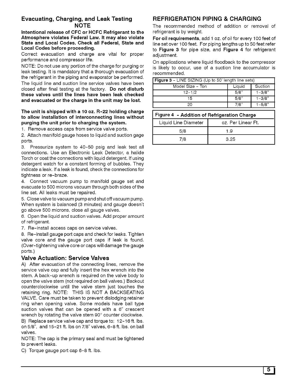
REFRIGERATION PIPING & CHARGING
The recommended method of addition or removal of
refrigerant is by weight.
For oil requirements, add 1 oz. of oil for every 100 feet of
line set over 100 feet. For piping lengths up to 50 feet refer
to Figure 3 for pipe size, and Figure 4 for refrigerant
adjustment.
On applications where liquid floodback to the compressor
is likely to occur, use of a suction line accumulator is
recommended.
Figure 3 -LINE SIZING (Up to 50' length line sets)
Model Size - Ton Liquid Suction
12-1/2 5/8" 1 - 3/8"
15 5/8" 1-3/8"
20 7/8" 1-5/8"
Figure 4-Addition of Refrigeration Charge
Liquid Line Diameter oz. Per Linear Ft.
5/8 1.9
7/8 3.25
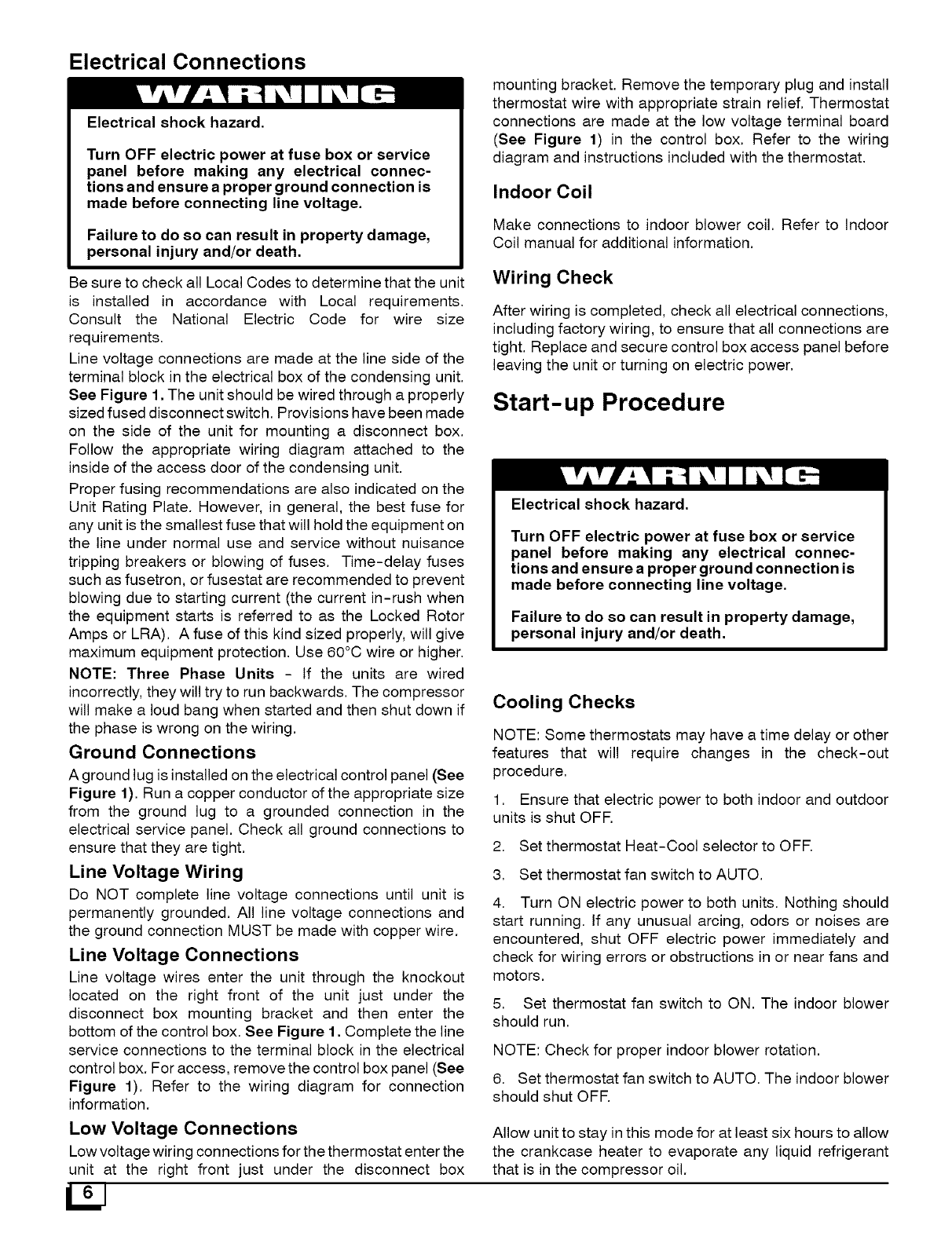
Electrical Connections
Electrical shock hazard.
Turn OFF electric power at fuse box or service
panel before making any electrical connec-
tions and ensure a proper ground connection is
made before connecting line voltage.
Failure to do so can result in property damage,
personal injury and/or death.
Be sure to check all Local Codes to determine that the unit
is installed in accordance with Local requirements.
Consult the National Electric Code for wire size
requirements.
Line voltage connections are made at the line side of the
terminal block in the electrical box of the condensing unit.
See Figure 1. The unit should be wired through a properly
sized fused disconnect switch. Provisions have been made
on the side of the unit for mounting a disconnect box.
Follow the appropriate wiring diagram attached to the
inside of the access door of the condensing unit.
Proper fusing recommendations are also indicated on the
Unit Rating Plate. However, in general, the best fuse for
any unit is the smallest fuse that will hold the equipment on
the line under normal use and service without nuisance
tripping breakers or blowing of fuses. Time-delay fuses
such as fusetron, or fusestat are recommended to prevent
blowing due to starting current (the current in-rush when
the equipment starts is referred to as the Locked Rotor
Amps or LRA). A fuse of this kind sized properly, will give
maximum equipment protection. Use 60°C wire or higher.
NOTE: Three Phase Units - If the units are wired
incorrectly, they will try to run backwards. The compressor
will make a loud bang when started and then shut down if
the phase is wrong on the wiring.
Ground Connections
A ground lug is installed on the electrical control panel (See
Figure 1). Run a copper conductor of the appropriate size
from the ground lug to a grounded connection in the
electrical service panel. Check all ground connections to
ensure that they are tight.
Line Voltage Wiring
Do NOT complete line voltage connections until unit is
permanently grounded. All line voltage connections and
the ground connection MUST be made with copper wire.
Line Voltage Connections
Line voltage wires enter the unit through the knockout
located on the right front of the unit just under the
disconnect box mounting bracket and then enter the
bottom of the control box. See Figure 1. Complete the line
service connections to the terminal block in the electrical
control box. For access, remove the control box panel (See
Figure 1). Refer to the wiring diagram for connection
information.
Low Voltage Connections
Low voltage wiring connections for the thermostat enter the
unit at the right front just under the disconnect box
L2J
mounting bracket. Remove the temporary plug and install
thermostat wire with appropriate strain relief. Thermostat
connections are made at the low voltage terminal board
(See Figure 1) in the control box. Refer to the wiring
diagram and instructions included with the thermostat.
Indoor Coil
Make connections to indoor blower coil. Refer to Indoor
Coil manual for additional information.
Wiring Check
After wiring is completed, check all electrical connections,
including factory wiring, to ensure that all connections are
tight. Replace and secure control box access panel before
leaving the unit or turning on electric power.
Start-up Procedure
Electrical shock hazard.
Turn OFF electric power at fuse box or service
panel before making any electrical connec-
tions and ensure a proper ground connection is
made before connecting line voltage.
Failure to do so can result in property damage,
personal injury and/or death.
Cooling Checks
NOTE: Some thermostats may have a time delay or other
features that will require changes in the check-out
procedure.
1. Ensure that electric power to both indoor and outdoor
units is shut OFF.
2. Set thermostat Heat-Cool selector to OFF.
3. Set thermostat fan switch to AUTO.
4. Turn ON electric power to both units. Nothing should
start running. If any unusual arcing, odors or noises are
encountered, shut OFF electric power immediately and
check for wiring errors or obstructions in or near fans and
motors.
5. Set thermostat fan switch to ON. The indoor blower
should run.
NOTE: Check for proper indoor blower rotation.
6. Set thermostat fan switch to AUTO. The indoor blower
should shut OFF.
Allow unit to stay in this mode for at least six hours to allow
the crankcase heater to evaporate any liquid refrigerant
that is in the compressor oil.
7. Set thermostatabove room temperature.Set
thermostatHeat-Coolselectorswitchto COOL.Set
thermostatbelow indicatedroom temperature.The
contactorwillcloseatthecondensingunitandtheindoor
blowershouldstartrunning.
The compressorsand outdoorfans(s)will run. If any
unusualarcing,odorsornoisesareencountered,shutOFF
electricpowerimmediatelyandcheckforwiringerrorsor
obstructionsinornearfansandmotors.Checkforproper
rotationoffanmotors.Fansshouldpullairinthroughthe
condensingcoiland blowout throughthe top grills.If
motorsoperateinreverserotation,linepolarityof3phase
powermustbechanged.
NOTE:Thecompressorshaveafiveminuteanti-cycle
delaythatisactivatedwheneverthecompressorsareshut
off.Forinstance,if theunitismanualshutoffwhenthe
compressorsarerunningandtheunitisturnedbackontwo
minuteslater,itwillbeanadditionalthreeminutesbefore
thecompressorswillrestart.
8. Withtheunitoperating,closealldoors,windowsand
otheropeningsinthe building.Setthethermostatto the
desiredsetting.Theunitmayrunseveralhoursorevena
full dayto reducethe initialheatand moisturein the
building.Thisisnormalforanyairconditioningsystem.
9. Aftertheunithasbeenoperatingforanhourormore,
checkductworkfor sweating.If ductworkis sweating,
additionalinsulationwithavaporbarrierisrequired.
10. Ensurethatcondensateis drainingproperlyfrom
indoorunit.
Unit Maintenance
The unit should be inspected and cleaned on an annual
basis by a qualified technician. This should include
checking for adequate clearances, electrical connections,
duct connections /blockages, air filters, air flow,
lubrication, and operational performance of system. Coils
may require cleaning, The coil should always be cold
when cleaning, Use an alkaline based cleaner only,
Cleaning a hot coil or using an acid based cleaner will
remove the paint from the fins and may clog the coil.
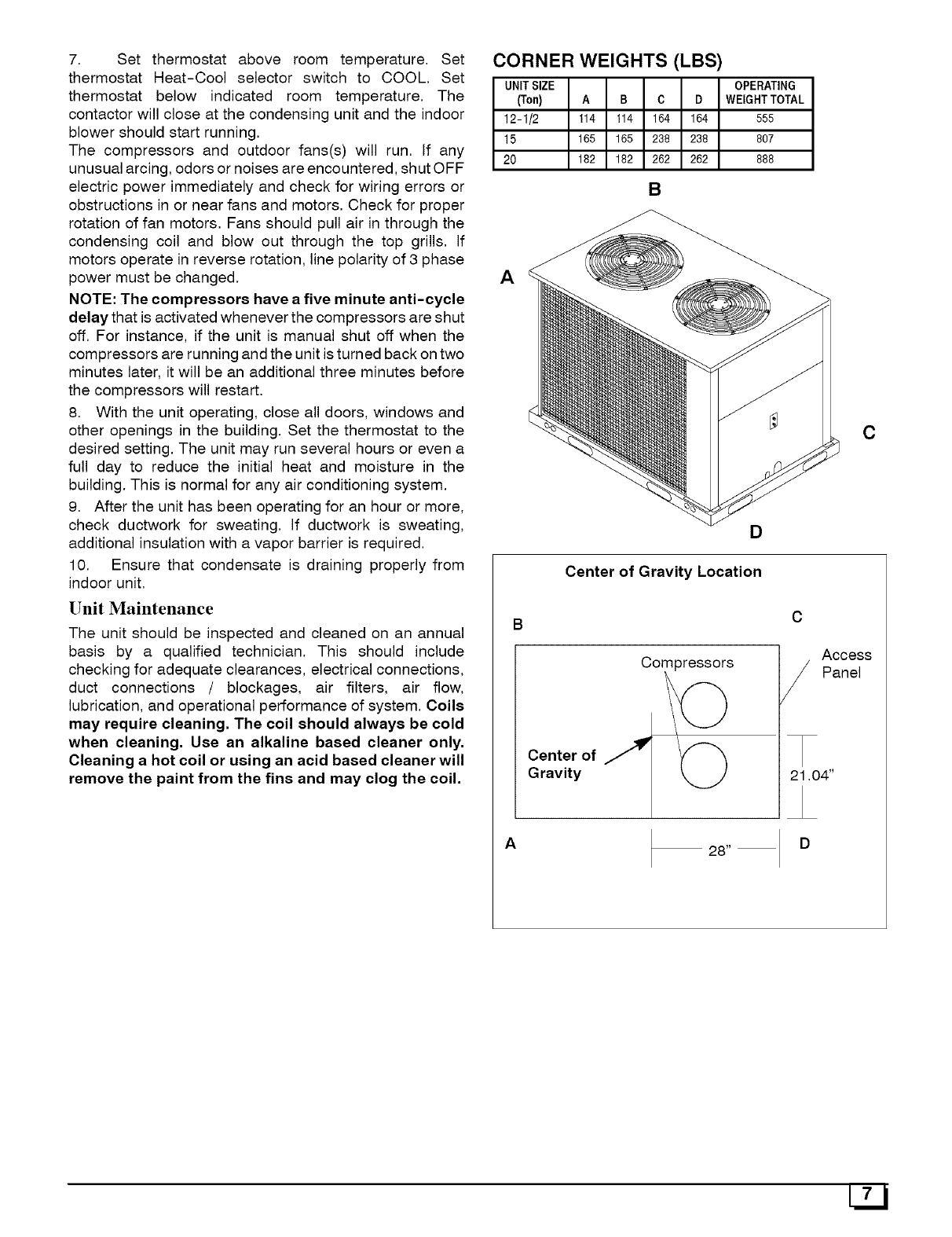
CORNER WEIGHTS (LBS)
UNITSIZE OPERATING
(Ton) A B C D WEIGHTTOTAL
12-1/2 114 114 164 164 555
15 165 165 238 238 807
20 182 182 262 262 888
B
A
D
Center of Gravity Location
B
Compressors
Center of S
Gravity
A28"
C
C
Access
Panel
21,04"
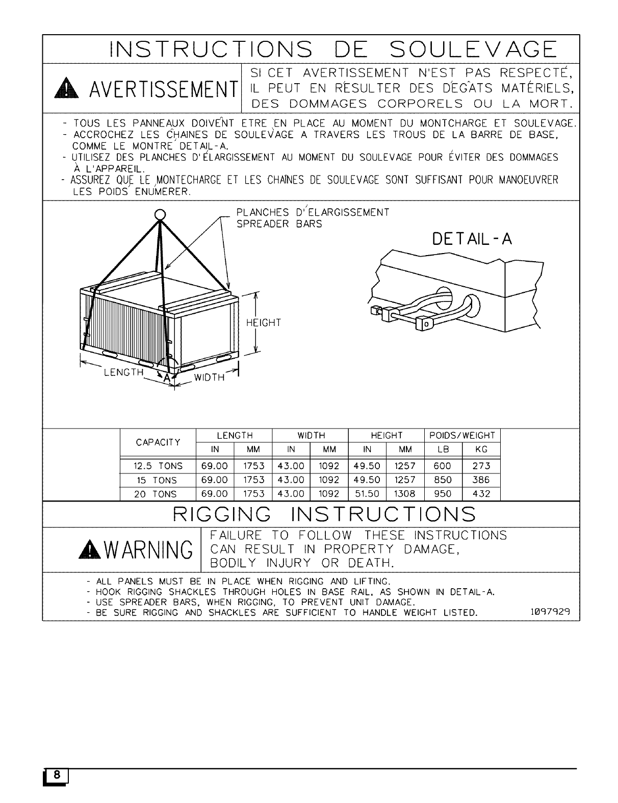
INSTRUCTIONS DE SOULEVAGE
s, CETAVERT_SSEMENTNESTPASRESPECTE,
,AVERTISSEMENTIL PEUT EN R'ESULTER DES D'EG_ATS MAT_-RIELS,
DES DOMMAGES CORPORELS OU LA MORT.
- TOUS LES PANNEAUX DOIVENT ETRE EN PLACE AU MOMENT DU MONTCHARGE ET SOULEVAGE.
- ACCROCHEZ LES CHAINES DE SOULEVAGE A TRAVERS LES TROUS DE LA BARRE DE BASE,
COMME LE MONTRE DETAIL-A.
- UTILISEZ DES PLANCHES D'ELARGISSEMENT AU MOMENT DU SOULEVAGE POUR EVlTER DES DOMMAGES
L'APPAREIL.
- ASSUREZ QUE LEjMONTECHARGE ET LES CH_ES DE SOULEVAGE SONT SUFFISANT POUR MANOEUVRER
LES POIDS ENUMERER.
q _ _ PLANCHES
_ I SPREADER
LENGTH
CAPACITY IN
/
D' ELARGISSEMENT
BARS
DETAIL-A
WIDTH HEIGHT POIDS/WEIGHT
MM IN MM IN MM LB KG
12.5 TONS 69.00 175,3 4,3.00 1092 49.50 1257 600 27,3
15 TONS 69.00 1753 43.00 1092 49.50 1257 850 386
20 TONS 69.00 175.3 4.3.00 1092 51.50 1508 950 4.32
RI
WARNING
GGING INSTRUCTIONS
FAILURE TO FOLLOW THESE INSTRUCTIONS
CAN RESULT IN PROPERTY DAMAGE,
BODILY INdURY OR DEATH.
- ALL PANELS MUST BE IN PLACE WHEN RIGGING AND LIFTING.
- HOOK RIGGING SHACKLES THROUGH HOLES IN BASE RAIL, AS SHOWN IN DETAIL-A.
- USE SPREADER BARS, WHEN RIGGING, TO PREVENT UNIT DAMAGE.
- BE SURE RIGGING AND SHACKLES ARE SUFFICIENT TO HANDLE WEIGHT LISTED. 18£7£29
INTERNATIONAL COMFORT PRODUCTS
LIMITED WARRANTY CERTIFICATE
For Cooling & Heating Products
SAVE THIS CERTIFICATE. It gives you specific legal rights, and you may also have other rights which may vary from state to state and
province to province.
If your unit needs servicing, contact a qualified dealer or qualified service technician of your choice. When requesting service, please have the model
and serial number from each unit in your heating and/or cooling system readily available. If your dealer needs assistance, the distributor is available to
provide support and we, in turn, support its efforts.
Fill in the installation date and model and serial numbers of the unit in the space provided below and retain this Limited Warranty for your files.
GENERAL TERMS
Subject to the conditions and limitations stated herein, during the term of this Limited Warranty, we will provide a replacement for any functional
component part (as defined below) of your unit found to be defective in materials or workmanship. The term ofthis Limited Warranty is five years from
installation on Residential Products and one year from installation on Commercial Products. Except as otherwise stated in the "Additional Terms"
section, this Limited Warranty covers only the original purchaser and subsequent transferees, and only while the unit remains at the site of the original
installation (except for mobile home installations), and onty if the unit is installed inside the continental United States, Puerto Rico, Alaska, Hawaii or
Canada. In addition, the Limited Warranty applies only if the unit is installed and operated in accordance with the printed instructions accompanying the
unit, and in compliance with alt applicable installation and building codes and good trade practices. As used in this Limited Warranty, "installation"
means the original installation of the unit.
TH ERE ARE EXCEPTIONS to this Limited Warranty as described on the reverse side of this page. All replacement parts will be warranted for the
unused portion of the warranty coverage period on the unit. The part to be replaced must be returned by the dealer to a distributor that sells products for
International Comfort Products, in exchange for the replacement part. In lieu of providing a replacement part, we may, at our sole option, refund to you
an amount equal to the distributor's component purchase price from us, or provide to you acredit equal to that amount to be applied toward the purchase
of any new unit that we distribute. If a credit for a new unit is given in tieu of a replacement part, the rating plate from the unit being replaced must be
submitted on a warranty claim, and you r dealer must make the unit being replaced available to our distributor for disposition. As a condition to warranty
coverage, the unit must receive yearly maintenance, as described in the owner's manual, by a dealer. Satisfactory proof of yearly service by a dealer
may be required.
"Functional component parts" include only the following: blower motor, unit-mounted sensors & timers, condenser motor, evaporator coil, condenser
coil, condenser fan, capacitor, transformer, single-phase strip heat elements, expansion device, reversing valve, solenoid valve, service valve,
electronic and electro-mechanical control board, ignitor, ignition module, draft inducer assembly, burner pilot, gas valve, limit control, pressure switch,
relays and contactors, blower wheel, interlock switch, crosslighter, pilot shield, gas & oil burners, oil pump assembly, accumulators and factory installed
driers and strainers.
This Limited Warranty DOES NOT COVER any labor, material, refractory chambers, oii nozzles, refrigerant, refrigerant inspection and refrigerant
reclaiming, freight and/or handling charges associated with any repair or replacement and such charges will be your responsibility.
Toestablish the installation date for any purpose under this Limited Warranty, you must retain the original records that can establish the installation date
ofyour unit. Ifyou donot providesuchdocumentsthe start dateoftheterm ofthis LimitedWarrantywillbe based uponthedate ofunit manufacture, ptus
thirty (30) days. In establishing that the required yearly service has occurred, you must furnish proof of yearly service by a qualified service technician.
This Limited Warranty does not cover: (a) failure or damages caused by accident, abuse, negligence, misuse, riot, fire, flood, or Acts of God (b)
damages caused by operating the unit where there is a corrosive atmosphere containing chlorine, fluorine, or any other damaging chemicals (other
than those found in a normal residential environment) (c) damages caused by an unauthorized alteration or repair of the unit affecting its stability or
performance (d) damages caused by improper matching or application of the unit or the unit's components (e) damages caused by failing to provide
proper maintenance and service to the unit in accordance with this Limited Warranty Certificate and the printed instructions originally provided with the
unit (f) any expenses incurred for erecting, disconnecting, or dismantling the unit (g) parts or supplies used in connection with service or maintenance,
such as refrigerant, refractory chambers, oil nozzles, filters, or belts (h) damage, repairs, inoperation or inefficiency resulting from faulty installation or
application (i) electricity or fuel costs or any increase in electricity or fuel cost whatsoever including additional or unusual use of supplemental electric
heat (j) units which have not had the required yearly maintenance described elsewhere in this limited warranty.
In no event shall we be liable for any incidental, consequential, or special damages or expenses in connection with any use or failure of this unit.
We have not made. do not make. and hereby disclaim any implied condition or implied warranty of fitness for a particular use or purpose, and
anv implied condition or implied warrantv of merchantabilitv, to the fu Ilest extent allowed bv law. We make no express or implied warranties
except as stated in this Limited Warrantv certificate.
No one is authorized to change this Limited Warranty or to create for us any other obligation or liability in connection with this unit. Any implied
warranties shall last for the term of the expressed warranty contained herein. Some states and provinces do not allow the exclusion or limitation of
incidental or consequential damages or do not allow limitations onhow long an implied warranty or condition lasts, so the above limitations or exclusions
may not apply to you. The provisions of this Limited Warranty are in addition to and not a modification of or subtraction from any statutory warranties and
other rights and remedies provided by law.
Please refer to reverse side of this page for additional terms.
Model No.
Serial No. Date Installed
Effective on units installed After July 1, 2002,
USA: International Comfort Products Corporation (USA) • 650 Hell-Quaker Avenue * P.O. Box 128 • Lewisburg, Tennessee 37091 • (931-270-4100)
CANADA: International Comfort Products division of UTC Canada Corporation • 6060 Burnside Court, Unit 1, Mississauga, Ontario L5T 2T5
(905-795-8113).
Manufacturers of Airquest, Arcoaire, Clare, Comfortmaker, Dettson, Hell, Keeprite, Lincoln, Tempstar and other quality brand name private label
products.
Part No. 401 06 1010 18 (Orig. 8/9/2002)
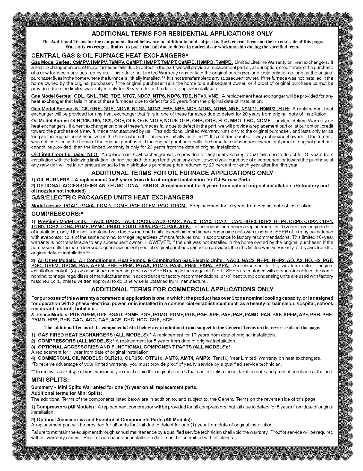
ADDITIONAL TERMS FOR RESIDENTIAL APPLICATIONS ONLY
The Additional Terms for the components listed below are in addition to, and subject to, the General Terms on the reverse side of this page.
Warranty coverage is limited to parts that fail due to defect in materials or workmanship during the specified term.
CENTRAL GAS & OIL FURNACE HEAT EXCHANGERS*
Gas Model Series: C9MPV. HgMPV. TgMPV. CgMPT. H9MPT. T9MPT. C9MPD. HgMPD. TgMPD: Limited Lifetime Warranty on heat exchangers. If
a heat exchanger on one of these furnaces fails due to defect in the part, we will provide a replacement part or, at our option, credit toward the purchase
of a new furnace manufactured by us. This additional Limited Warranty runs only to the original purchaser, and tasts only for as tong as the originat
purchaser tives in the home where the furnace is initially installed.** It is not transferable to any subsequent owner. Ifthe furnace was not installed in the
home owned by the original purchaser, if the original purchaser setls the home to a subsequent owner, or if proof of originat purchase cannot be
provided, then the limited warranty is only for 20 years from the date of original installation.
Gas Model Series: GDL. GNL. TNE. TDE. NTC7. NDC7. NTP6. NDP6. TDE. NTV6. VNE: A replacement heat exchanger will be provided for any
heat exchanger that fails in one of these furnaces due to defect for 25 years from the originat date of installation.
Gas Model Series: NTC6. GNE. GDE. NDN6. NTG3. NDN3. FBF. NBF. NDF. NTN3. NTN6. NNE. N9MPI. N9MP2. FUH: A replacement heat
exchanger witt be provided for any heat exchanger that faits in one of these furnaces due to defect for 20 years from original date of installation.
Oil Model Series: OLR(105, 160, 182), OCF, OLE OUF, NOLE NOUF, OLB, OHB, ODH, FLO, MBO, LBO, NOMF: Limited Lifetime Warranty on
heat exchangers. Ifa heatexchangerononeofthesefurnacesfailsduetodefectinthepart, wewitl provide a replacement part or, at our option, credit
toward the purchase of a new furnace manufactured by us. This additional Limited Warranty runs only to the original purchaser, and tasts only for as
long as the original purchaser lives in the home where the furnace is initially installed.** It is not transferable to any subsequent owner. If the furnace
was not installed in the home of the original purchaser, if the original purchaser sells the home to a subsequent owner, or if proof of original purchase
cannot be provided, then the limited warranty is only for 20 years from the date of original installation.
Oil Fired Floor Furnace: NFO: A replacement heat exchanger witl be provided for any heat exchanger that faits due to defect for 10 years from
installation with the following limitation: during the sixth through tenth year, any credit toward your purchase of a component or toward the purchase of
any new unit wilI be in an amount equal to the distributor's purchase price reduced by 20 percent for each year after the fifth year.
ADDITIONAL TERMS FOR OIL FURNACE APPLICATIONS ONLY
1) OIL BURNERS - A replacement for 5 years from date of original installation for Oil Burner Parts.
2) OPTIONAL ACCESSORIES AND FUNCTIONAL PARTS: A replacement for 5 years from date of original installation. (Refractory and
oil nozzles not included)
GAS/ELECTRIC PACKAGED UNITS HEAT EXCHANGERS
Model series: PGAD. PGAA. PGMD. PGME. PGF. GPFM. PGC. GPCM: A replacement for 10 years from original date of installation.
COMPRESSORS:*
1) Premium Model Units: HAC0. HAC2. HAC4. CAC0. CAC2. CAC4. KAC0. TCA0. TCA2. TCA4. HHP0. HHP2. HHP4. CliP0. CliP2. CliP4.
TCH0. TCH2. TCH4. PGME. PYMC. PHAD. PGAD. PA95. PAPC. PAK. APK: Tothe original purchaser a replacement for 10 years from original date
of installation, only if the unit is installed with factory matched coils, except air conditioner condensing units with a nominal SEER of 10 may be matched
with evaporator coils of the same nominal tonnage regardless of manufacturer and in accordance to factory recommendations. This limited 10-year
warranty is not transferable to any subsequent owner. HOWEVER, if the unit was not installed in the home owned by the original purchaser, if the
purchaser sells the home to a subsequent owner, or if proof of original purchase cannot be provided, then the limited warranty is only for 5 years from the
original date of installation.**
2) All Other Models: Air Conditioners. Heat PumPs. &Combination Gas/Electric Units: NAC0. NAC2. NHP0. NHP2. AO. A2. HO. H2. PGF.
PGC, GPFM, GPCM, PAE APFM, PHE HPFM, PGAA, PGMD, PA55, PH55, PAPA, PYPA: A replacement for 5 years from date of original
installation, onty if: (a) air conditioner condensing units with SEER rating in the range of 10 to 11 SEER are matched with evaporator coils of the same
nominal tonnage regardless of manufacturer and in accordance to factory recommendations, or (b) heat pump condensing units are used with factory
matched coils, unless written approval to do otherwise is obtained from manufacturer.
ADDITIONAL TERMS FOR COMMERCIAL APPLICATIONS ONLY
For purposes of this warranty a commercial application is one in which: the product has over 5 tons nominal cooling capacity, or is designed
for operation with 3 phase electrical power, or is installed in a commercial establishment such as a beauty or hair salon, hospital, school,
restaurant, church, hotel etc..
3-Phase Models: PGF, GPFM, GPF, PGAD, PGME, PGB, PGMG, PGMF, PGS, PGE, APE, PAE, PAB, PAMD, PAS, PAl=,APFM, APF, PHB, PHE,
PYMD, HPB, PHS, CAC, ACC, CAE, ACE, CHC, HCC, CHE, HCE:
The additional Terms of the components listed below are in addition to and subject to the General Terms on the reverse side of this page.
1) GAS FIRED HEAT EXCHANGERS (ALL MODELS):* A replacement for 10 years from date of originat installation.
2) COMPRESSORS (ALL MODELS):* A replacement for 5 years from date of original installation.
3) OPTIONAL ACCESSORIES AND FUNCTIONAL COMPONENT PARTS (ALL MODELS):*
A replacement for 1 year from date of original installation.
4) COMMERCIAL OIL MODELS: OLR210, OLR350, OTF210, AMT3, AMT4, AMP3: Ten(10) Year Limited Warranty on heat exchangers.
*To receive advantage of your limited warranty, you must provide proof of yearly service by a qualified service technician.
**To receive advantage of your warranty, you must retain the original records that can establish the installation date and proof of purchase of the unit.
MINI SPLITS:
Summary - Mini Splits Warranted for one (1) year on all replacement parts.
Additional terms for Mini Splits:
The additional Terms of the components listed below are in addition to, and subject to, the General Terms on the reverse side of this page.
1) Compressors (All Models): A replacement compressor wili be provided for atI compressors that faii due to defect for 5 years from date of original
installation.
2) Optional Accessories and Functional Components Parts (All Models):
A replacement part will be provided for alt parts that fail due to defect for one (1) year from date of original installation.
Failu re to maintain the equipment through annual maintenance by a qualified service technician shall void the warranty. Proof of service wili be required
with ati warranty claims. Proof of purchase and installation date must be submitted with ali claims.
