ICP Furnaces/Heaters Manual L0602183
User Manual: ICP ICP Furnaces/Heaters Manual ICP Furnaces/Heaters Owner's Manual, ICP Furnaces/Heaters installation guides
Open the PDF directly: View PDF ![]() .
.
Page Count: 19
GUK Series
SAFETY CONSIDERATIONS
Installing and servicing heating equipment can be hazardous due to gas and electrical components. Only trained and qualified personnel
should install, repair, or service heating equipment.
Untrained service personnel can perform basic maintenance functions such as cleaning and replacing air filters. All other operations must
be performed by trained service personnel. When working on heating equipment, observe precautions in the literature, on tags, and on
labels attached to or shipped with the unit and other safety precautions that may apply.
Follow all safety codes. In the United States, follow all safety codes including the current edition National Fuel Gas Code (NFGC) NFPA No.
54/ANSIZ223.1. In Canada, refer to the current edition of the National Standard Canada CAN/CGA-B149.1 - and .2-M91 Natural Gas and
Propane Installation Codes (NSCNGPIC). Wear safety glasses and work gloves. Have fire extinguisher available during starf-up and ad-
justment procedures and service calls.
Recognize safety information. This is the safety-alert symbol_J...._,i . When you see this symbol on the furnace and in instructions or manu-
als, be alert to the potential for personal injury.
Understand the signal word DANGER, WARNING, or CAUTION. These words are used with the safety-alert symbol. DANGER identifies
the most serious hazards will result in severe personal injury or death. WARNINGsignifiesahazardthatcouldresultinpersonalinjuryor
death. CAUTION is used to identify unsafe practices which would result in minor personal injury or product and property damage.
These instructions cover minimum requirements and conform to existing national standards and safety codes. In some instances, these
instructions exceed certain local codes and ordinances, especially those that may not have kept up with changing residenlial construction
practices. We require these instructions as a minimum for a safe installation.
Table of Contents
1, Safe Installation Requirements.............. 1
2. Installation .............................. 3
3. Combustion& Ventilation Air ............... 4
4. Vent and CombustionAir Piping ............. 7
5. GasSupplyand Piping ..................
6. Electrical Wiring .......................
7. Ductworkand Filter ....................
S. Checksand Adjustments ................
9, FurnaceMaintenance ...................
12
14
16
17
18
D_sign Cer_tled
_AG.A.
Manufactured By: lnter_Uity products Corporation (USA)
Lavergne, Tlq USA 37086
This furnace is not designed for use in mobile
homes, trailers or recreational vehicles. Such
use could result in property damage, bodily in-
jury and/or death.
LP1 1-18-96 441 011002 00
LP1 formerly 7212-114
r:
1. Safe InstallationRequirements
Installation or repairs made by unqualified
persons can result in hazards to you and others.
Installation MUST conform with local codes or, in
the absence of local codes, with codes of the
country having jurisdiction.
The information contained in this manual is
intended for use by a qualified service technician
familiar with safety procedures and equipped
with the proper tools and test instruments.
Failure to carefully read and follow all instruc-
tions in this manual can result in furnace
malfunction, property damage, personal injury
and/or death.
NOTE: This furnace is design certified by the American Gas Association
and the Canadian Gas Association for installation in the United States and
Canada. Refer to the appropriate codes, along Figure I with this manual,
for proper installation.
•This furnace is NOT approved for installation in mobile
homes, trailers or recreation vehicles.
• Do NOT use this furnace as a construction heater.
• Use only the Type of gas approved for this furnace (see Rating
Plate on unit). Overtiring will result in failure of heat exchanger and
cause dangerous operation.
+ Do NOT use open flame to test for gas leak.
• Ensure adequate combustion and ventilation air is provided to the
furnace.
• Seal supply and return air ducts.
•The vent system MUST be checked to determine that it is the cor-
rect type and size.
• Install correct filter type and size.
•Unit MUST be installed so electrical components are protected
from direct contact with water.
NOTE: it is the personal responsibility and obligation of the customer to
contact a qualified installer to ensure that the installation is adequate and
conforms to governing codes and ordinances.
Carbon Monoxide Poisoning Hazard.
This furnace can NOT be common vented or
connected to any type B, BW or Lvent or vent
connector, nor to any portion of a factory-built or
masonry chimney. If this furnace is replacing a
previously common-vented furnace, it may be
necessary to resize the existing vent line and
chimney to prevent oversizing problems for the
other remaining appliance(s). See Venting and
Combustion Air Check in Gas Vent Installation
section. This furnace MUST be vented to the
outside.
Failure to properly vent this furnace or other
appliances can result in property damage,
personal injury and/or death.
1LLJ
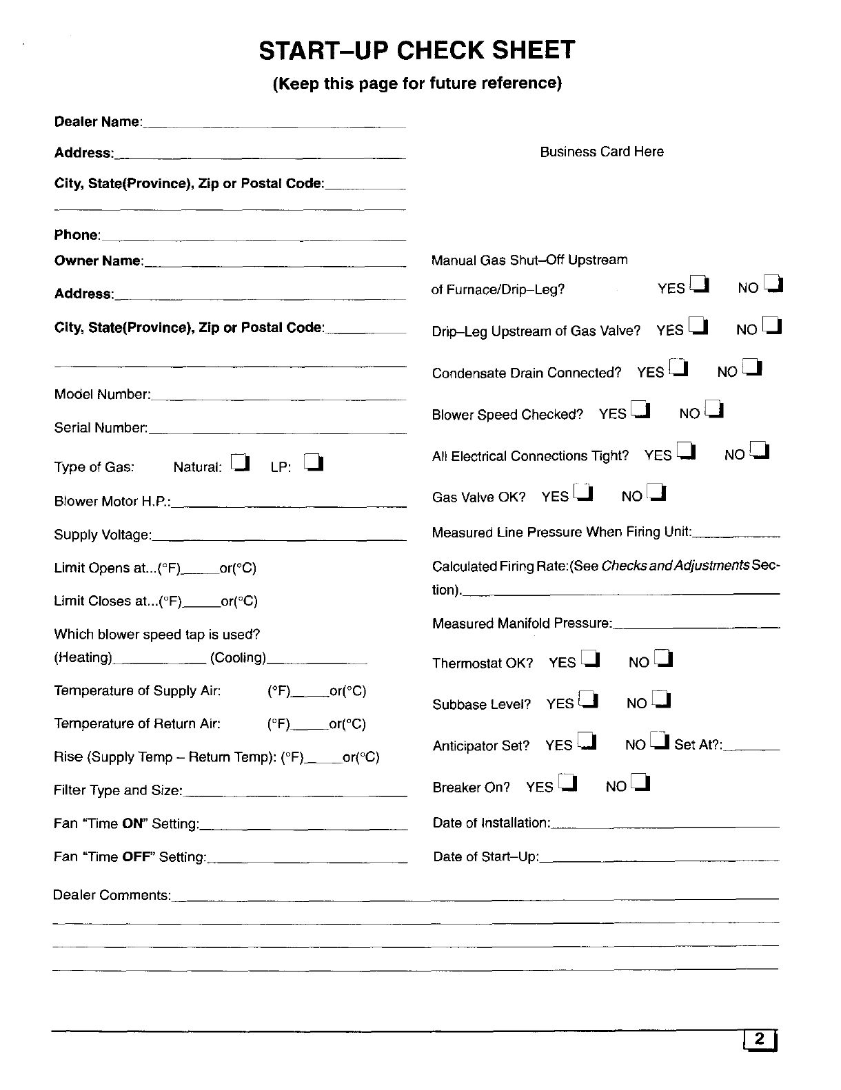
START-UP CHECK SHEET
(Keep this page for future reference)
Dealer Name:
Address:
City, State(Province), Zip or Postal Code:
Business Card Here
Phone:
Owner Name:
Address:
City, State(Province), Zip or Postal Code:
Model Number:
Serial Number:
Natural: [_1 LP: [_1
Type of Gas:
Blower Motor H.P.:
Supply Voltage:
Limit Opens at...(°F) or(°C)
Limit Closes at...(°F) or(°C)
Which blower speed tap is used?
(Heating)_ (Cooling)
Temperature of Supply Air: (°F) or(°C)
Temperature of Return Air: (°F) or(°C)
Rise (Supply Temp - Return Temp): (°F) or(°C)
Filter Type and Size:
Fan 'q'ime ON" Setting:
Fan "Time OFF" Setting:
Manual Gas Shut-Off Upstream
of Furnace/Drip-Leg? YES
Drip-Leg Upstream of Gas Valve? YES _1
Condensate Drain Connected? YES _1
NO[_
NO
NO_1
Blower Speed Checked? YES _J NO _1
All Electrical Connections Tight? YES [_1 NO _1
Gas Valve OK? YES [a NO _J
Measured Line Pressure When Firing Unit:
Calculated Firing Rate:(See ChecksandAdjustmentsSec-
tion).
Measured Manifold Pressure:
Thermostat OK? YES _1
Subbase Level? YES _1
Anticipator Set? YES [_
Breaker On? YES _-_
Date of Installation:
Date of Start-Up:
NO_.,i
Noel
NO _1 Set At?:
NO [3
Dealer Comments:
2. Installation
Locationand Clearances
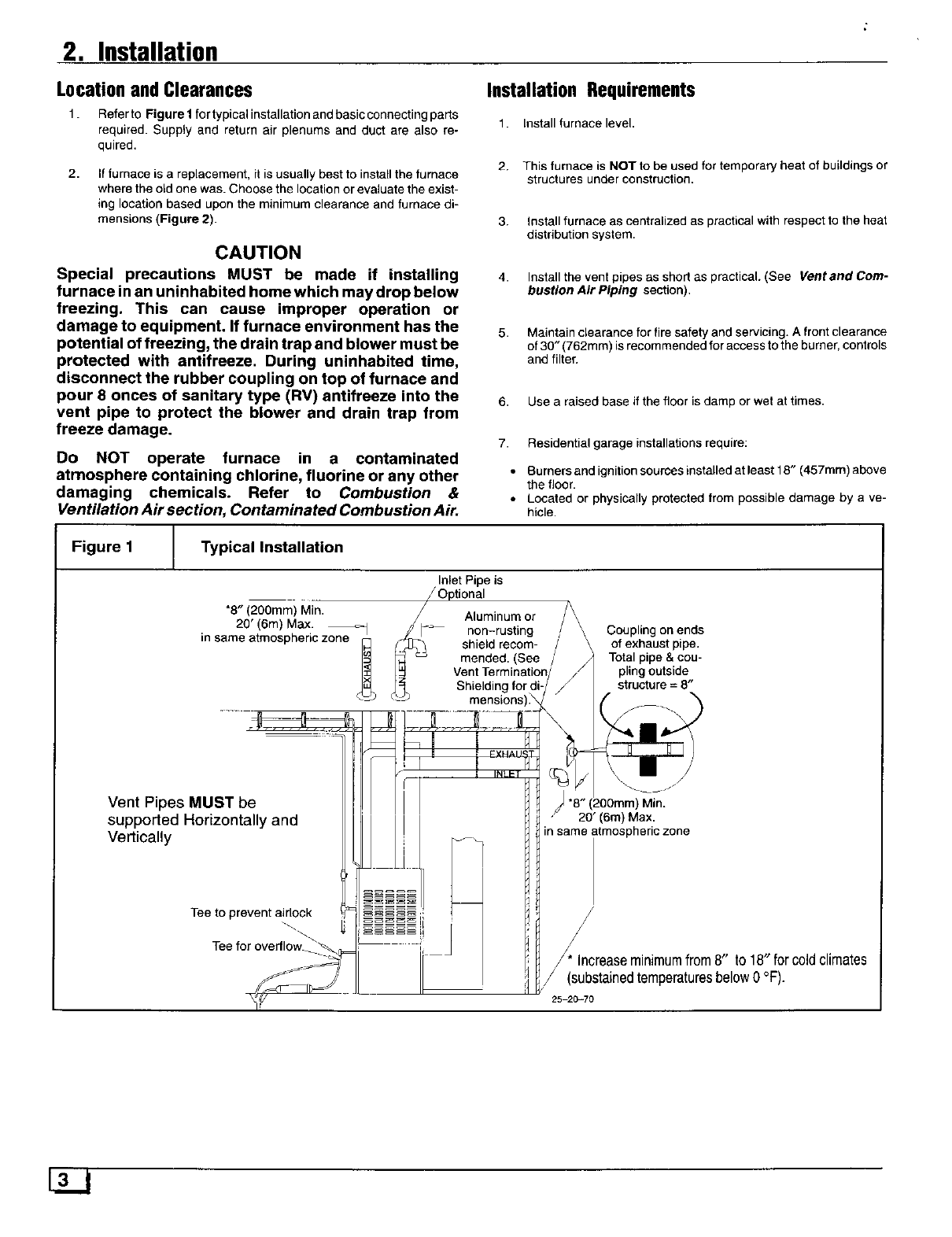
1. Refer to Figure 1 for typicalinstallation and basic connecting parts
required. Supply and return air plenums and duct are also re-
quired.
2. If furnace is a replacement, it is usually best to install the furnace
where the old one was. Choose the location or evaluate the exist-
ing location based upon the minimum clearance and furnace di-
mensions (Figure 2).
CAUTION
Special precautions MUST be made if installing
furnace in an uninhabited home which may drop below
freezing. This can cause improper operation or
damage to equipment. If furnace environment has the
potential of freezing, the drain trap and blower must be
protected with antifreeze. During uninhabited time,
disconnect the rubber coupling on top of furnace and
pour 8 onces of sanitary type (RV) antifreeze into the
vent pipe to protect the blower and drain trap from
freeze damage.
Do NOT operate furnace in a contaminated
atmosphere containing chlorine, fluorine or any other
damaging chemicals. Refer to Combustion &
Ventilation Air section, Contaminated Combustion Air.
Installation Requirements
1. Install furnace level.
2. This furnace is NOT to be used for temporary heat of buildings or
structures under construction.
3. install furnace as centralized as practical with respect to the heat
distribution system.
4. Install the vent pipes as shod as practical. (See Vent and Com-
bustion Air Piping section).
5. Maintain clearance for fire safety and servicing. A front clearance
of 30" (762mm) is recommended for access to the burner, controls
and filter.
6. Use a raised base if the floor is damp or wet at times.
7. Residential garage installations require:
Burners and ignition sources installed at least 18" (457mm) above
the floor.
Located or physically protected from possible damage by a ve-
hicle.
Figure 1 Typical Installation
*8" (200mm) Min.
20' (6m) Max.
in same atmospheric zone
Inlet Pipe is
//Optional
Aluminum or
non-rusting
_t_, shield recom-
mended. (See
Vent Terminatior
_ Shielding for di
- mensions)_
Vent Pipes MUST be
supported Horizontally and
Vertically
Tee to prevent airlock
Tee for overflow _'_q=
Ir
/\ Coupling on ends
\of exhaust pipe.
/_ Total pipe & cou-
// piing outside
/structure = 8"
20" (6m) Max.
in same atmospheric zone
_ Increaseminimumfrom8" to 18" for coldclimates
/(substained temperatures below 0 °F).
/
25 20=70
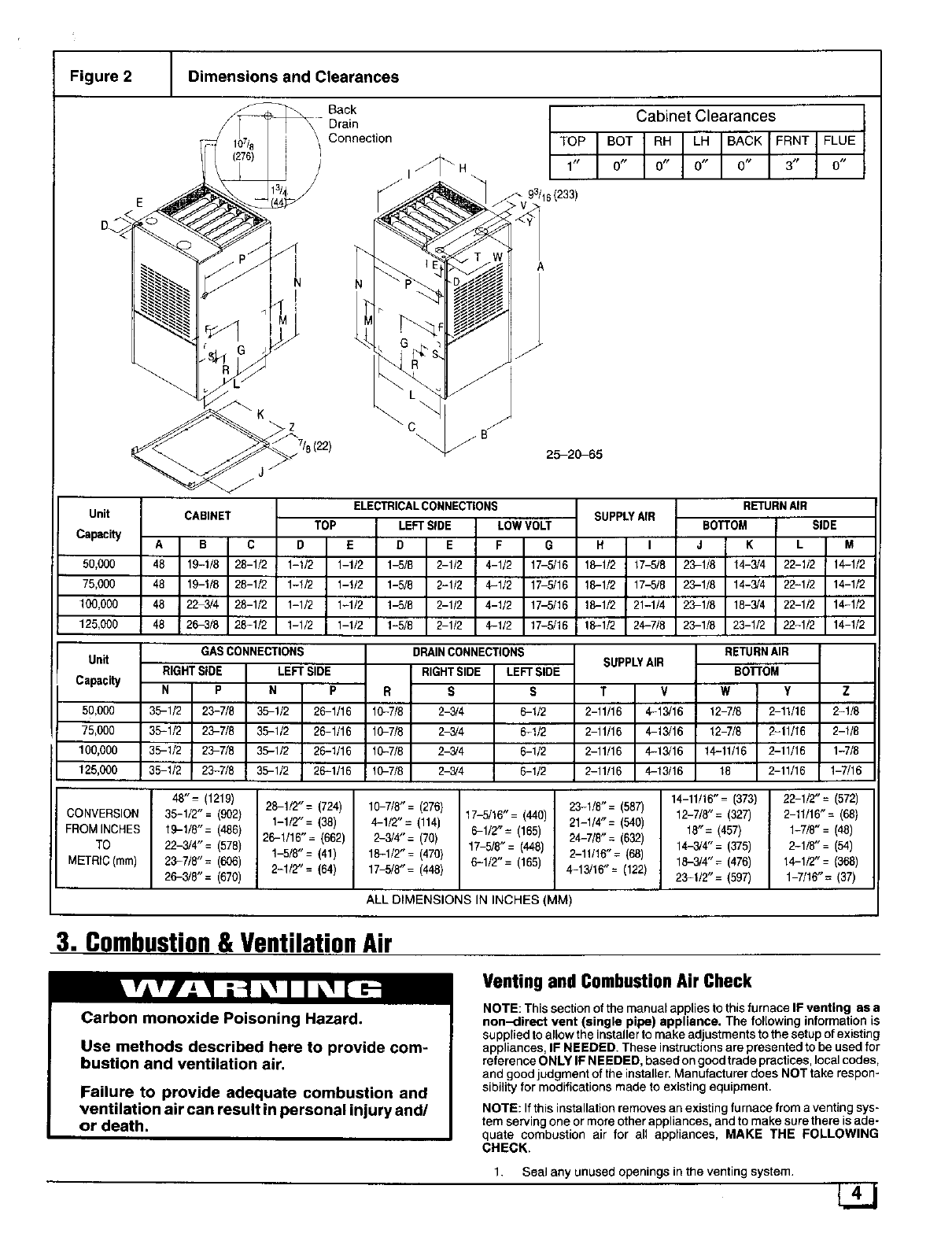
Figure 2 Dimensions and Clearances
7/a(22)
Unit
Capacity
50,000
75,000
100,000
125,000
CABINET
Back
Drain
Connection
I_ H 1"
\C /
\/B"
\ 25-20_S5
ELECTRICALCONNECTIONS
TOP LEFTSIDE LOW VOLT
A B C D E D E F G
48 19-1/8 28-1/2 1-1/2 1-1/2 1-5/8 2-1/2 4-1/2 17-5/16
48 19-1/8 28-1/2 1-!/2 1-!/2 1-5/8 2-1/2 4-1/2 17 5/16
48 22 3/4 28-1/2 1-1/2 1-1/2 1J5/8 2-1/2 4-1/2 17-5/16
48 26-3/8 28-1/2 1-1/2 1-1/2 1-5/8 2 1/2 4-1/2 17-5/16
Cabinet Clearances
TOP BOT RH LH BACK FRNT FLUE
0_ 0_ 0_ 0_ 3_ 0_
SUPPLYAIR
HI
16-1_ 17-5/8
16-1_ 17_/8
16-1_ 21-1_
16-1_ 24-7/8
RETURNAIR
BOTTOM SIDE
J K L M
29-1/8 14-3/4 22-1/2 14-1/2
23-1/8 14-3/4 22-1/2 14-1/2
29-1/8 18-3/4 22-1/2 14-1/2
23-1/8 23-1/2 22-1/2 14-1/2
Unit
Capacity
50,000
75,000
100,000
125,000
GASCONNECTIONS
RIGHT SIDE LEFT SIDE
N P N P R
36-1/2 23-7/8 36-1/2 26-1/16 19-7/8
36-1/2 23-7/8 36-1/2 26-1/16 10-7/8
36-1/2 29-7/8 35-1/2 26-1/16 10-7/8
36-1/2 23-7/8 36-1/2 26-1/16 10-7/8
DRAINCONNECTIONS
RIGHTSIDE LEFT SIDE
S S
2-3/4 6-112
2-3/4 6-1/2
2-3/4 6-1/2
2-3/4 6-1/2
SUPPLYAIR
T V
2-!1/16 4-13/16
2-11/16 4-13/16
2-11/16 4-13/16
2-11/1, 4-13/16
RETURNAIR
Bo'rroM
W Y Z
!2-7/8 2-11/16 2-1/8
12-7/8 2-11/16 2-1/8
14-11/16 2-11/16 1-7/8
18 2-11/16 1-7/16
48"= (1219) 26-1/2"= (724) 19-7/8"= (276) 29-1/8"= (587) 14-11/16"= (373) 22-1/2"= (572)
CONVERSION 36-1/2"= (902) 1-1/2"= (38) 4-1/2"= (114) 17-5/16"= (440) 21-1/4"= (540) 12-7/8"= (327) 2-11/16"= (68)
FROM INCHES 19-1/8"= (486} 26-1/16"= (662) 2-3/4"= (70) 6-1/2"= (165) 24-7/8"= (632) 18"= (457) 1-7/8"= (48)
TO 22-3/4"= (578) 1-5/8"= (41) 16-1/2"= (470) 17-5/8_= (448) 2-11/16"= (68) 14-3/4"= (375) 2-1/8"= (54)
METRIC (ram) 23-7/8"= (606) 2-1/2"= (64) 17-5/8_= (448) 6-1/2"= (165) 19-3/4"= (476) 14-1/2"= (368)
26-3/8"= (670) 4-13/16"= (122) 29-1/2"= (597) 1-7/16"= (37)
ALL DIMENSIONS IN INCHES (MM)
3. Combustion& VentilationAir
Venting and Combustion Air Check
Carbon monoxide Poisoning Hazard.
Use methods described here to provide com-
bustion and ventilation air.
Failure to provide adequate combustion and
ventilation air can result in personal injury and/
or death.
NOTE: This section of the manual applies to this furnace IF venting as a
non-direct vent (single pipe) appliance. The following information is
supplied to allow the installer to make adjustments to the setup of existing
appliances, IF NEEDED. These instructionsare presented to be used for
reference ONLY IF NEEDED, based on good trade practices, local codes,
and good judgment of the installer. Manufacturer does NOT take respon-
sibility for modifications made 1o existing equipment.
NOTE: If this installation removes an existing furnace from a venting sys-
tem serving one or more other appliances, and to make sure there is ade-
quate combustion air for all appliances, MAKE THE FOLLOWING
CHECK,
1. Seal any unused openings in the venting system. 4L.L]
2,
3.
4.
5.
6.
7.
8.
Visually inspect the venting system for proper size and horizontal
pitch to ensure there is no blockage or restriction, leakage, corro-
sion or other deficiencies which could cause an unsafe condition.
Insofar as is practical, close all doors and windows and all doors
between the space in which the appliance(s) remaining connected
to the venting system are located and other spaces of the building.
Turn on clothes dryers and any appliance not connected to the
venting system. Turn on any exhaust fans, such as range hoods
and bathroom exhausts, so they will operate at maximum speed.
Do not operate a summer exhaust fan. Close fireplace dampers.
Follow the lighting instructions for each appliance being inspected.
Adjust thermostat so appliance(s) will operate continuously.
Allow 5 rain utes of main burner operation, then check for spillage at
the draft hood relief opening of each appliance. Use the flame of a
match or candle (Figure 3).
After it has been determined that each appliance vents properly,
return doors, windows, appliances etc. to their normal condition.
If improper venting is observed, the cause MUST be corrected us-
ing the appropriate tables in code books of country having judsdic-
tion.
NOTE: Ifflame polls towards draft hood, this indicates sufficient infiltration
air.
NOTE: Non direct vent appliances occupying same enclosed space as
furnace MUST have enough air for proper combustion and ventilation. All
duct or openings for supplying combustion and ventilation air must comply
with the gas and electrical codes of the country having jurisdiction.
When the installation is complete, check that all appliances have ade-
quate combustion air and are venting properly. See VentingAnd Combus-
tion Air Check in this manual.
Air Openingsand ConnectingDucts
t,
2.
3.
4.
5.
Total input rating for all non direct vent gas appliances MUST be
considered when determining free area of openings.
Connect ducts or openings directly to outside.
When screens are used to cover openings, they MUST be no less
than 1/4" (6mm) mesh.
The minimum dimension of rectangular air ducts MUST NOT be
less than 3" (75mm).
When sizing grille or louver, use the free area of opening. If free
area is NOT stamped or marked on grill or louver, assume a 20%
free area for wood and 60% for metal.
Confined Space Installation
NOTE: A confined space is defined as an area with less than 50 cubic
feet( 1.4m 3) per 1,000 BTUH input rating for all gas appliances installed in
the area.
Requirements
1. Provide confined space with sufficient air for proper combustion
and ventilation of flue gases using horizontal or vertical ducts or
openings.
2. Figure 4 illustrate how to provide combustion and ventilation air. A
minimum of two permanent openings, one inlet and one outlet, are
required.
3. One opening MUST be within 12" (300mm) of the floor and the se-
cond opening within 12" (300mm) of the ceiling.
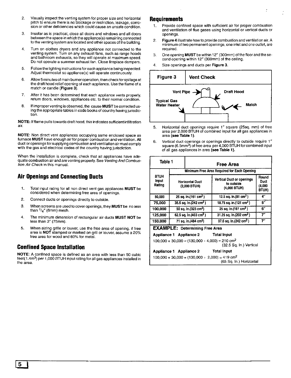
4. Size openings and ducts per Figure 3.
Figure 3 Vent Check
Vent Pipe "_! IJ/ Draft Hood
Match
5. Horizontal duct openings require 1" square (25sq. mm) of free
area per 2,000 BTUH of combined input for all gas appliances in
area (see Table 1).
6. Vedical duct openings or openings directly to outside require 1"
square (6.5mm 3) of free area per 4,000 BTUH for combined input
of all gas appliances in area (see Table 1).
Table1 Free Area
MinimumFreeAreaRequiredforEachOpening
BTUH
Input HorizontalDuct
Rating (2,000BTUH)
50,000 25 sq.in.(161cm2)
75,000 35.5 sq. in.(242cm2)
100,OOO 50 sq. In.(323cm2)
125,000 62.5 eq. In.(403cm2)
150,000 71 sq. in.(484cm2)
VerticalDuctor openings Round
to outside Duct
(4,000 BTUH) (4,000
BTUH)
12.5sq.in.(81 cm2) 4"
15.75sq.in.(121cm2) 5"
25 sq.in.(161cm2) 6"
31.25sq.in.(202crnz) 7"
37.5sq. in.(242cm2) 7"
EXAMPLE: Determining Free Area
Appliance 1 Appliance 2 Total Input
100,OOO+ 30,000 =(130,000 ÷4,DO0) =210 cm2
(32.5 Sq. In.) Vertical
Appliance 1 Appliance 2 Totallnput
100,000 + 3D,O00 = (130,000 +2,000) - 419 cm2
(65 Sq. In.) Horizontal
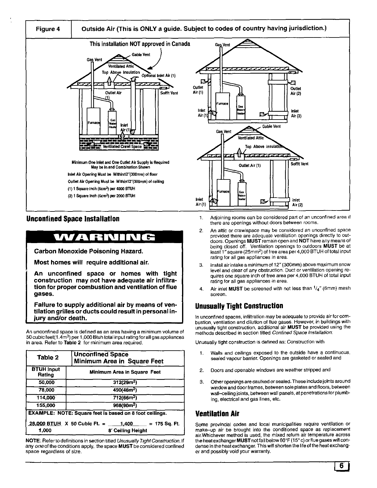
Figure 4 Outside Air (This is ONLY aguide. Subject to codes of country having jurisdiction.)
This installationNOTapprovedinCanada
_SGable Vent
Op:ion..n.t.ir,t,
I-] IN
=m
MinimumOneinlet and One Outlet Air Supply is Required
Maybe in andCombination Shown
InletAir Opening Must be Within12"(30Omm}of floor
Outlet Air Opening Must be Within12"(300mm)of ceiling
(1) t SquareInch(6cm2)per 40006TUH
(2) 1 Square Inch (6cm2)per 2000 BTUH
/
Outlet
Air(t)
Fumace G_
ttaten m
Inlet
Air(1
Outlet
Air(2)
Inlet
Air(2)
Inlet I
Air(1)
GasVent GableVent
SoffitVent
inlet
UnconfinedSpaceInstallation
Carbon Monoxide Poisoning Hazard.
Most homes will require additional air.
An unconfined space or homes with tight
construction may not have adequate air infiltra-
tion for proper combustion and ventilation of flue
gases,
Failure to supply additional air by means of ven-
tilation grilles or ducts could result in personal in-
jury and/or death.
An unconfined space is defined as an area having a minimum volume of
50 cubic feet( 1.4m 3) per 1,000 Btu h total input rating for all gas appliances
in area. Refer to Table 2 for minimum area required.
Table 2 Unconfined Space
Minimum Area in Square Feet
BTUH Input Minimum Area in Square Feet
Rating
50,000 312(29m 2)
78,000 490(46m 2)
114,000 712(66m 2)
155,000 968(90m 2)
EXAMPLE: NOTE: Square feet is based on 8 foot ceilings.
28.000 BTUH X 50 Cubic Ft. = 1,400 =175 Sq. Ft.
1,000 8' Ceiling Height
NOTE: Refer to definitions in section titled Unusually Tight Construction. if
any one of the conditions apply, the space MUST be considered confined
space regardless of size.
1. Adjoining rooms can be considered part of an unconfined area if
there are openings without doors between rooms.
2. An attic or crawlspace may be considered an unconfined space
provided there are adequate ventilation openings directly to out-
doors. Openings MUST remain open and NOT have any means of
being closed off. Ventilation openings to outdoors MUST be at
least 1"square (25ram 2) of free area per 4,000 BTUH of total input
rating for all gas appliances in area.
3. Instafl air intake a minimum of f 2" (300ram) above maximum snow
level and clear of any obstruction. Duct or ventilation opening re-
quires one square inch of free area per 4,000 BTUH of total input
rating for all gas appliances in area,
4. Air inlet MUST be screened with not less than 1/4" (6mm) mesh
screen.
UnusuallyTight Construction
in unconfined spaces, infiltration may be adequate to provide air for com-
bustion, ventilation and dilution of flue gases. However, in buildings with
unusually tight construction, additional air MUST be provided using the
methods described in section titled Confined Space Installation:
Unusually tight construction is defined as: Construction with
1. Wails and ceilings exposed to the outside have a continuous,
sealed vapour barrier. Openings are gasketed or sealed and
2. Doors and openable windows are weather sthpped and
3. Other openings are caulked or sealed. These include joints around
window and door frames, between sole plates and floors, behNeen
wall-ceiling joints, between wall panels, at penetrations for plumb-
ing, electrical and gas lines, etc.
VentilationAir
Some provincial codes and local municipalities require ventilation or
make-up air be brought into the conditioned space as replacement
air, Whichever method is used, the mixed return air temperature across
the heat exchanger MUST not fall below 60 °F (15° c) or flue gases will con-
dense in the heat exchanger. This will shorten the life of the heat exchang-
er and possibly void your warranty.
L2J
4. VentandCombustionAirPiping
Carbon monoxide poisoning, fire and explosion
hazard.
Read and follow all instructions in this section.
Failure to properly vent this furnace can result in
property damage, personal injury and/or death.
Dual Certified Furnace
This fu rnace is certified as a category t¥ appliance and is dual certified as
a direct vent furnace using outside air for combustion or it can use air from
inside the structure for combustion. The INLET air pipe is optional. If com-
bustion air comes from inside the structure, adequate make up air MUST
be provided to compensate for oxygen burned. See Confined Space
installation in the Combustion and Ventilation Air chapter. If combus-
tion air is drawn from outside the structure, it MUST be taken from the
same atmospheric pressure zone as the vent pipe.
Contaminated Combustion Air
Installations in certain areas or types of structures will increase the expo-
sure to chemicals or Halogens which may harm the furnace.
The following areas or types of structures may contain or have exposure
to the substances listed below. The installation must be evaluated careful-
ly as it may be necessary to provide outside air for combustion.
Q Commercial buildings.
• Buildings with indoor pools.
• Furnaces installed in laundry rooms.
• Furnaces installed in hobby or craft rooms.
• Furnaces installed near chemical storage areas.
• Permanent wave solutions for hair.
• Chlorinated waxes and cleaners.
• Chlorine based swimming pool chemicals.
• Water softening chemicals.
• De-icing salts or chemicals.
• Carbon tetrachloride.
• Halogen type refrigerants.
• Cleaning solvents (such as perchloroethylene).
• Printing inks, paint removers, varnishes, etc..
• Hydrochloric acid.
• Sulfuric Acid.
• Solvent cements and glues.
• Antistatic fabric softeners for clothes dryers.
• Masonry acid washing materials.
Vent and Combustion Air Piping Guidelines
1. Determine the best routing and termination for the vent pipe and
air inlet pipe when used by referring to all of the instructions and
guidelines nth s Sect on.
2. Determine the size required for the vent pipe and air inlet pipe
(when used).
3. Loosely assemble all venting parts without adhesive (pipe joint
cement) for correct fit before final assembly.
4.
5.
6.
Use of vertical piping is preferred because there will be some mois-
ture in the flue gases that may condense as it leaves the vent pipe
(See Special Instruction For Horizontal Vents).
The vent MUST exit the furnace at the top left side.
The vertical vent pipe MUST be supported so that no weight is al-
lowed to rest on the combustion blower.
7. Exhaust vent piping diameter MUST NOT be reduced.
8. All exhaust vent piping from the furnace to termination MUST slope
upwards, away from furnace, a minimum of 1/4" per foot of run
(6mm per 300mm).
9. Use DWV type long radius elbows whenever possible, as they pro-
vide for the minimum slope on horizontal runs and they provide
less resistance in the vent system. If DWV elbows cannot be used,
use two, 45 ° elbows when possible. On horizontal runs the elbows
can be slightly misaligned to provide the correct slope.
10. All horizontal pipe runs MUST be supported at least every five feet
with metal pipe strapping. NO sags or dips are permitted.
11. All vertical pipe runs MUST be supported every six feet where ac-
cessible.
12. The maximum pipe length is 40' (12m) total in the inlet or outlet
side of the system. Up to five, 90 ° elbows can be used on the inlet
orthe outlet. If more than five elbows ar_erequired, reduce the
length of both the inlet and exhaust pipes 5 (1.5m) for each addi-
tional elbow used, (See Vent Tables).
13. The minimum pipe run length is 2' (.6m).
14. The piping can be run in the same chase or ad acent to supply or
vent pipe for water supply or waste plumbing. It can also be run in
the same chase with a vent from another 90+ furnace.
NOTE: In NO case can the piping be run in a chase where temper-
atures can exceed 140 ° F. or where radiated heat from adjacent
surfaces would exceed 140 ° E
15. If installing as a direct-vent appliance, the vent outlet MUST be
installed to terminate in the same atmospheric pressure zone as
the combustion air inlet,
16. The vent system can be installed in an existing unused chimney
provided that:
• Both the exhaust vent and air intake run the length of the chimney.
• No other gas fired appliance or fireplace (solid fuel) is vented into
the chimney.
•The top of the chimney MUST be sealed flush or crowned up to
seal against rain or melting snow so ONLY the piping protrudes.
•The termination clearances shown in Figure 10 are maintained.
PipingInsulation Guidelines
NOTE: In general, chimneys on an outside wall and attics are exposed to
cold conditions which can cause the vent pipe to sweat from condensa-
tion. This can lead to moisture damage to living spaces. It is highly recom-
mended that piping inthese cases be insulated to insure proper protection
from condensation damage.
Use 1/2" (50mm) wall, closed cell, neoprene insulation or equivalent. If
Fiberglas ar equivalent insulation is used it must have a vapor barrier. Use
R values of 7 up to 10, R-11 if exposure exceeds 10'. if Fiberglas insula-
tion is used, exterior to the structure, the pipe MUST be boxed in and
sealed against moisture.
1. Insulate pipe when the exhaust vent passes through an uncondi-
tioned space or raceway.
2. g situations require pipe to be run on the exterior wall to reach a
suitable termination point, it MUST be properly insulated.
3. If it is necessary to insulate piping when an inactive chimney is
used as a chase, the top of the chimney MUST be sealed flush or
crowned up to seal against rain or melting snow so ONLY the pip-
ing protrudes,
4. When the vent or combustion air pipe height above the roof ex-
ceeds 30" (760ram), or if an exterior vertical rise ris used on a hori-
zontal vent to get above snow levels, the exterior portion MUST be
insulated.
5. When combustion air inlet piping is installed above a suspended
ceiling, the pipe MUST be insulated with moisture resistant insula-
tion such as Armaflex or other equivalent type of insulation.
6. Insulate combustion air inlet piping when run in warm, humid
spaces such as basements,
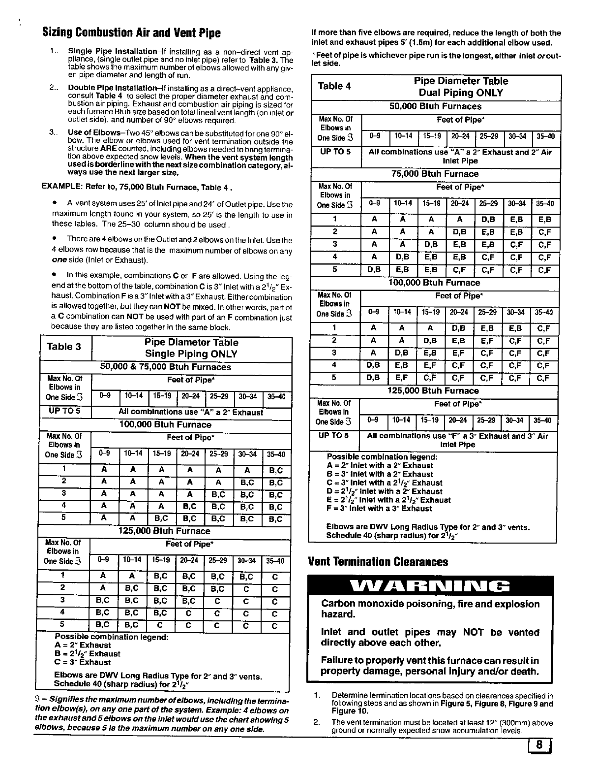
SizingCombustionAir andVent Pipe
1.. Single Pipe Installation-If installing as a non-direct vent ap-
pliance, (single outlet pipe and no inlet pipe) refer to Table 3. The
table shows the maximum number of elbows allowed with any giv-
en pipe diameter and length of run.
2.. Double Pipe Installation-If installing as a direct-vent appliance,
consult Table 4 to select the proper diameter exhaust and com-
bustion air piping. Exhaust and combustion air piping is sized for
each furnace Btuh size based on total lineal vent length (on inlet or
outlet side), and number of 90 ° elbows required.
3.. Use of Elbows-Two 45 ° elbows can be substituted for one 90 ° el-
bow. The elbow or elbows used for vent termination outside the
structure ARE counted, including elbows needed to bring termina-
tion above expected snow levels. When the vent system length
used is borderline with the next size combination category, al-
ways use the next larger size.
EXAMPLE: Refer to, 75,000 Btuh Furnace, Table 4.
• A vent system uses 25' of Inlet pipe and 24' of Outlet pipe. Use the
maximum length found in your system, so 25" is the length to use in
these tables. The 25-30 column should be used.
• There are 4 elbows on the Outlet and 2elbows on the Inlet. Use the
4 elbows row because that is the maximum number of elbows on any
one side (Inlet or Exhaust).
• In this example, combinations C or F are allowed. Using the leg-
end at the bottom of the table, combination Cis 3" Inlet with a 21/2" Ex-
haust. Combination F is a3" Inlet with a 3" Exhaust. Either combination
is allowed together, but they can NOT be mixed. In other words, part of
aCcombination can NOT be used with part of an F combination just
because they are listed together in the same block.
Table 3 Pipe Diameter Table
Single Piping ONLY
50,000 & 75,000 Btuh Furnaces
Max No. Of Feet of Pipe*
Elbowsin
OnsSide_ 0-9 110-14 115-19 120-24 120-29 130-. 135-40
UP TO 5 All combinations use "A" a 2" Exhaust
100,000 Btuh Furnace
Max No.Of Feet of Pipe*
Elbows in
OneSide_ 0-9 10-14 15-19 20-24 25-29 30-34 35-40
1 A A A A A A B,C
2 A A A A A B,C B,C
3 A A A A B,C B,C B,C
4 A A A B,C B,C B,C B,C
5 A A B,C B,C B,C B,C B,C
125,000 Btuh Furnace
Max No. Of Feet of Pipe*
Elbows in
OneSide_ 0-9 10-14 15-19 20-24 25-29 30-34 35-40
1 A A B,C B,C B,C B,C C
2 A B,C B,C B,C B,C C C
3 B,C B,C B,C B,C C C C
4 B,C B,C B,C C C C C
5 B,C B,C C C C C C
Possible combination legend:
A = 2" Exhaust
B = 21/2 "Exhaust
C = 3" Exhaust
Elbows are DWV Long Radius Type for 2" and 3" vents.
Schedule 40 (sharp radius) for ,_12/2"
3-Signifies the maximum number of elbows, including the termina-
tion elbow(s), on any one part of the system. Example: 4 elbows on
the exhaust and 5 elbows on the inlet would use the chart showing 5
elbows, because 5 is the maximum number on any one side.
If more than five elbows are required, reduce the length of both the
inlet and exhaust pipes 5' (1.5m) for each additional elbow used.
*Feet of pipe is whichever pipe run is the longest, either inlet orout-
let side.
Table 4 Pipe Diameter Table
Dual Piping ONLY
50,000 Btuh Furnaces
MaxNo. Of Feet of Pipe*
Elbowsin
OneSide_ 0-9 110-14 115-19 120-24 125-29 130-34 135-40
UP TO 5 All combinations use "A" a 2" Exhaust and 2" Air
Inlet Pipe
75,000 Btuh Furnace
MaxNo. Of Feet of Pipe*
Elbowsin
OneSide _0-9 10-14 15-19 20-24 25-29 30-34 35-40
1 A A A A D,B E,B E,B
2 A A A D,B E,B E,B C,F
3 A A D,B E,B E,B C,F C,F
4 A D,B E,B E,B C,F C,F C,F
5 D,B E,B E,B C,F C,F C,F C,F
100,000 Btuh Furnace
MaxNo. Of Feet of Pipe*
Elbowsin
OneSide_ 0-9 10-14 15-19 20-24 25-29 30-34 35-40
1 A A A D,B E,B E,B C,F
2 A A D,B E,B E,F C,F C,F
3 A D,B E,B E,F C,F C,F C,F
4 D,B E,B E,F C,F C,F C,F C,F
5 D,B E,F C,F C,F C,F C,F C,F
125,000 Btuh Furnace
MaxNo.Of Feet of Pipe*
Elbowsin
OneSide_ 0-9 110-14 115-19 120-24 120-29 130-34 135-40
UP TO 5 All combinations use "F" a 3" Exhaust and 3" Air
Inlet Pipe
Possible combination legend:
A = 2" Inlet with a 2" Exhaust
a = 3- Inlet with a 2" Exhaust
C = 3" Inlet with a 2112"Exhaust
D = 21/2" Inlet with a 2" Exhaust
E = 21/2"Inlet with a 21/2"Exhaust
F = 3" Inlet with a 3" Exhaust
Elbows are DWV Long Radius Type for 2" and 3" vents.
Schedule 40 (sharp radius) for _12/2"
Vent TerminationClearances
Carbon monoxide poisoning, fire and explosion
hazard.
Inlet and outlet pipes may NOT be vented
directly above each other.
Failure to properly vent this furnace can result in
property damage, personal injury and/or death.
1. Determine termination locations based on clearances specified in
following steps and as shown in Figure 5, Figure 8, Figure 9 and
Figure 10.
2. The vent termination must be located at least 12" (300ram) above
ground or normally expected snow accumulation levels.
3,
4.
5.
6,
Do NOT terminate over public walkways, Avoid areas where con-
densate may cause problems such as above planters, patios, or
adjacent to windows where steam may cause fogging.
The vent termination shall be located at least 4" (1220mm) horizon-
taUy from any electric meter, gas meter, regulator, and any relief
equipment. These distances apply ONLY to U,S. installations.
The vent termination is to be located at least 3' (914mm) above
any forced air inlet located within 10' (3m) ; and at least 10" (3m)
from a combustion air intake of another appliance, except another
direct vent furnace intake.
In Canada, the Canadian Fuel Gas Code takes precedence over
the preceding termination instructions.
5.
6.
7.
A condensa e pump MUST have an auxiliary safety switch to pre-
vent operation of furnace and resulting overlow of condensate in
the event of pump failure. The safety switch MUST be wired
through the R circuit ONLY (low voltage) to provide operation in ei-
ther heating or cooling modes.
Install an overflow line if routing to floor drain or sump pump. See
Figure I for example of proper routing and installation of overflow
line.
If the condensate drain has the potential for freezing, heat tape
must be used on the drain trap and condensate drain.
Connecting Furnace and Piping
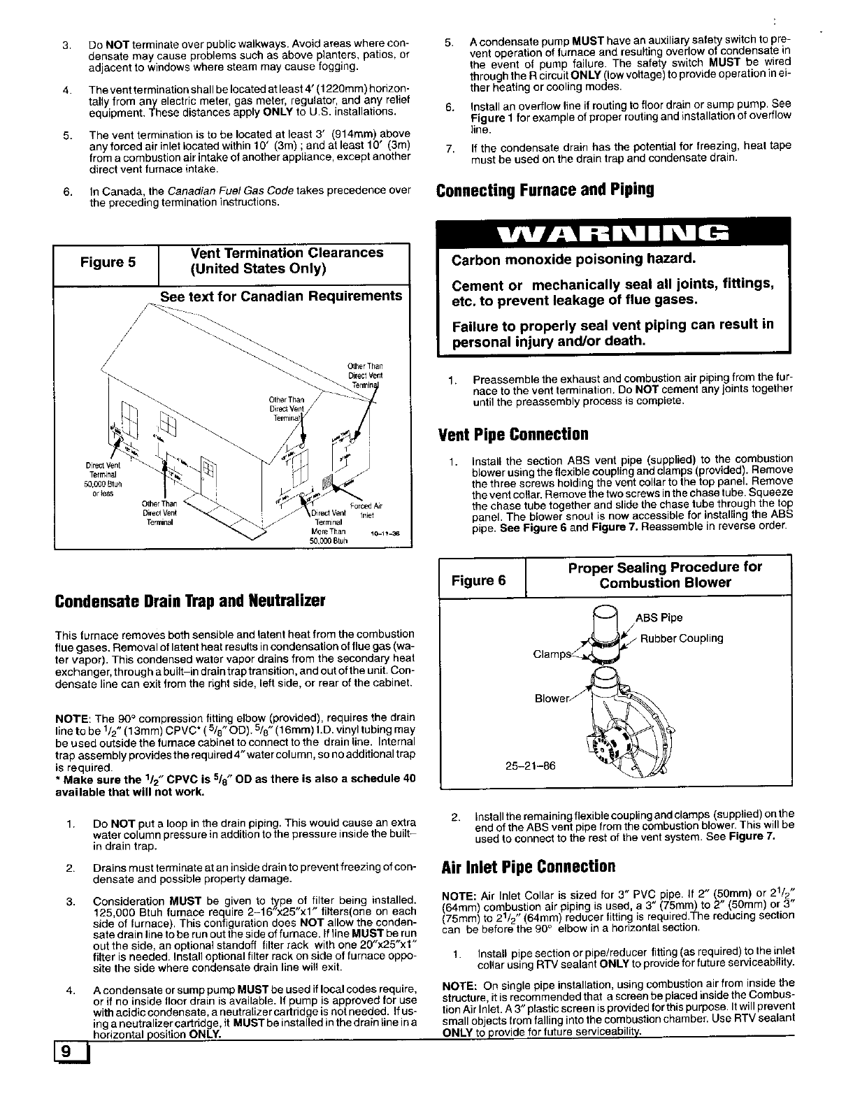
Vent Termination Clearances
Figure 5 (United States Only)
See text for Canadian Requirements
OtherThan
Direct Vent
Other Than
Direct Vent
Direct Vent
Terr_nal
50,C_0 Btuh
0flees
Carbon monoxide poisoning hazard.
Cement or mechanically seal all joints, fittings,
etc. to prevent leakage of flue gases.
Failure to properly seal vent piping can result in
personal injury and/or death.
1. Preassemble the exhaust end combustion air piping from the fur-
nace to the vent termination. Do NOT cement any joints together
until the preassembly process is complete.
Vent Pipe Connection
1, nsta the section ABS vent pipe supplied to the combustion
blowerusingthe flexible coupling and clamps provded. Remove
the three screws holding the vent collar to the top panel. Remove
the vent collar. Remove the two screws in the chase tube. Squeeze
the chase tube together and slide the chase tube through the top
panel. The blower snout is now accessible for installing the ABS
pipe. See Figure 6and Figure 7, Reassemble in reverse order.
Condensate Drain Trap and Neutralizer
This furnace removes both sensible and latent heat from the combustion
flue gases. Removal of latent heat results in condensation of flue gas (wa-
ter vapor). This condensed water vapor drains from the secondary heat
exchanger, through a built-in drain trap transition, and out of the unit. Con-
densate line can exit from the right side, left side, or rear of the cabinet.
NOTE: The 90 ° compression fitting elbow (provided), requires the drain
line to be 1/2" (13mm) CPVC* ( 5/8" OD). 5/8" (16mm) I.D. vinyl tubing may
be used outside the furnace cabinet to connect to the drain line. Internal
trap assembly provides the required 4"water column, so no additional trap
is required.
* Make sure the 1/2" CPVC is 5/8" OD as there is also a schedule 40
available that will not work.
Figure 6 Proper Sealing Procedure for
Combustion Blower
_ABS Pipe
Rubber Coupling
Clamps_,,_
Blower_,
25-21-86
1,
2.
3.
Do NOT put a loop in the drain piping. This would cause an extra
water column pressure in addition to the pressure inside the built-
in drain trap.
Drains must terminate at an inside drain to prevent freezing of con-
densate and possible property damage.
2. nstal the rema ningflexiblecouplingandciamps (supplied) onthe
end of the ABS vent pipe from the combustion blower. Ths w be
used to connect to the rest of the vent system. See Figure 7.
Consideration MUST be given to type of filter being installed.
125,000 Btuh furnace require 2-16"x25"x1" filters(one on each
side of furnace). This configuration does NOT allow the conden-
sate drain line to be run out the side of furnace. If line MUST be run
out the side, an optional standoff filter rack with one 20"x25"xl"
filter is needed, Install optional filter rack on side of furnace oppo-
site the side where condensate drain line will exit.
4. A condensate or sump pump MUST be used if local codes require,
or if no inside floor drain is available. If pump is approved for use
with acidic condensate, a neutralizer cartridge is not needed. If us-
ing a neutralizer cartridge, it MUST be installed in the drain line in a
horizontal position ONLY.
Air Inlet Pipe Connection
NOTE Ar net Collar is sized for 3" PVC pipe. If 2" 50ram) or 21/2
64ram combus on air piping is used, a 3" (75ram) to 2" 50mm) or 3
(75mm to 21/2 (64mm reducer fi ing is required.The reducing section
can be before the 90 ° elbow in a horizontal section.
1. nstaU pipe section or pipe/reducer fitting as required) to the inlet
collar using RTV sealant ONLY to provide for future serviceab ty.
NOTE: On single pipe installation, using combustion air from inside the
structure, it is recommended that a screen be placed inside the Combus-
tion Air Inlet. A 3" plastic screen is provided for this purpose, It will prevent
small objects from falling into the combustion chamber. Use RTV sealant
ONLY to provide for future serviceability.
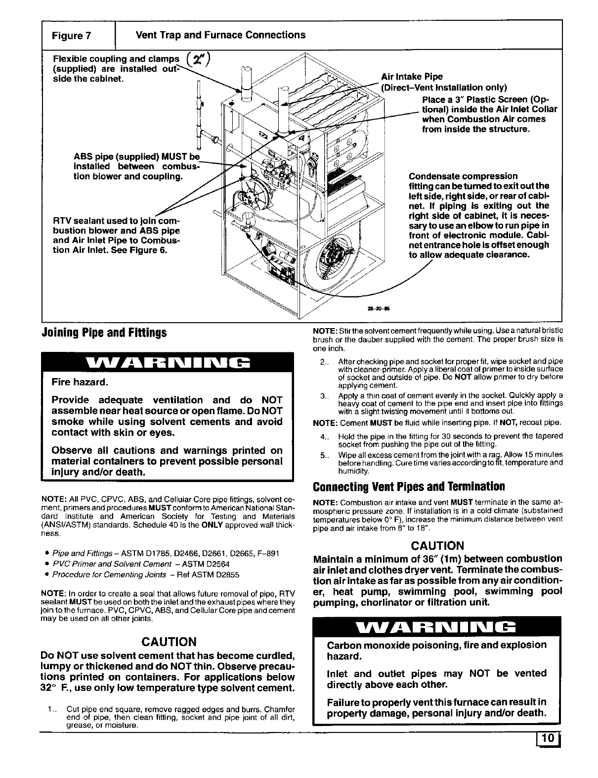
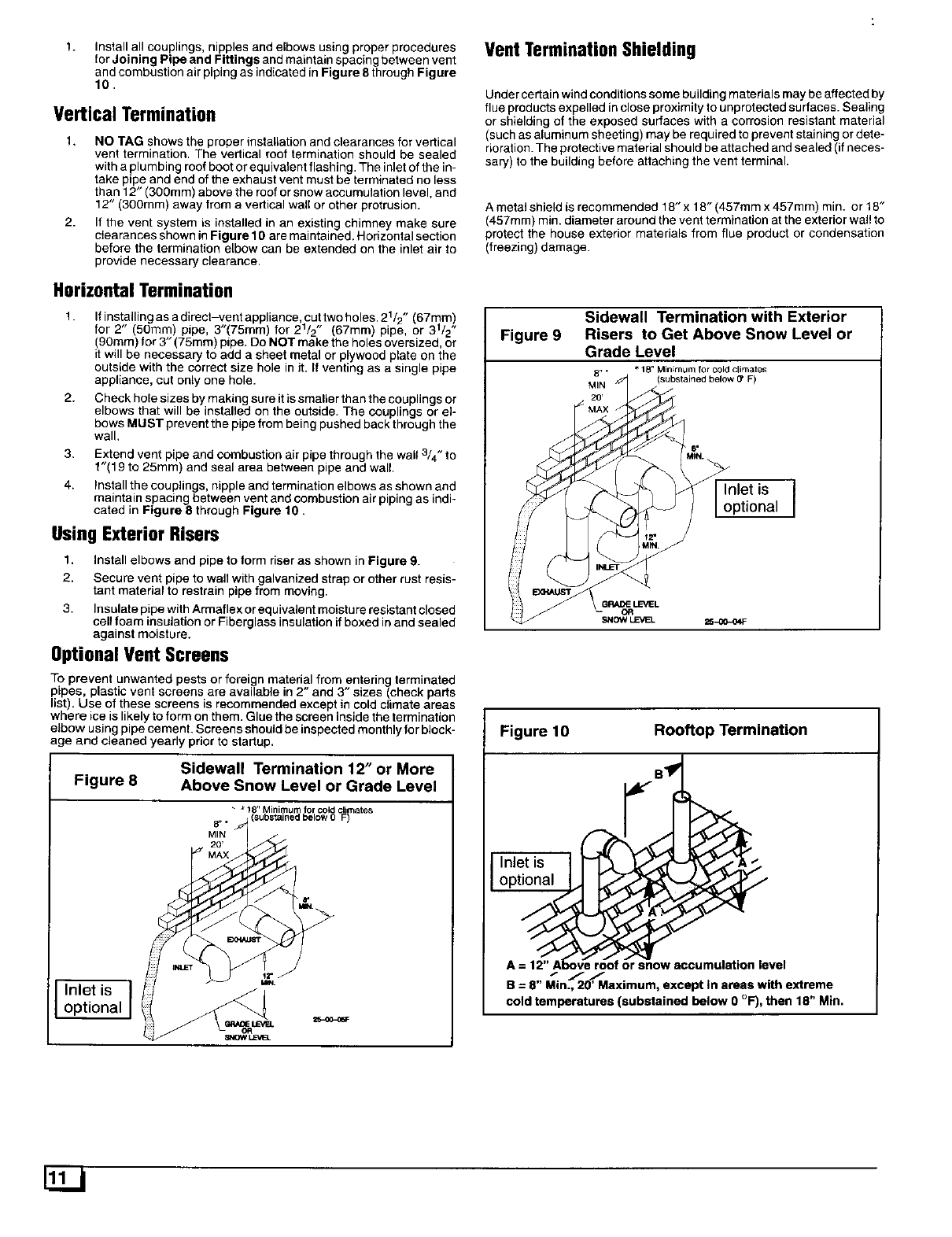
Figure 7 Vent Trap and Furnace Connections
coupling and clamps _._)
Flexible
(supplied) are installed
side the cabinet. Air Intake Pipe
"(Direct-Vent Installation only)
Place a 3" Plastic Screen (Op-
inside the Air Inlet Collar
when Combustion Air comes
from inside the structure.
ABS pipe (supplied) MUST be
installed between
tion blower and coupling.
RTV sealant used to join com-
bustion blower and ABS pipe
and Air inlet Pipe to Combus-
tion Air Inlet. See Figure 6.
Condensate compression
fitting can be turned to exit out the
left side, right side, or rear of cabi-
net. If piping is exiting out the
right side of cabinet, it is neces-
sary to use an elbow to run pipe in
front of electronic module. Cabi-
net entrance hole is offset enough
to allow adequate clearance.
Joining Pipe andFittings
Fire hazard.
Provide adequate ventilation and do NOT
assemble near heat source or open flame. Do NOT
smoke while using solvent cements and avoid
contact with skin or eyes.
Observe all cautions and warnings printed on
material containers to prevent possible personal
injury and/or death.
NOTE: All PVC, CPVC, ABS, and Cellular Core pipe fittings, solvent ce-
ment, primers and procedures MUST conform to American National Stan-
dard Institute and American Society for Testing and Materials
(ANSVASTM) standards. Schedule 40 is the ONLY approved wall thick-
ness.
•Pipe and Fittings- ASTM D1785, D2466, D2661, D2665, F-891
• PVC Primer and Solvent Cement - ASTM D2564
• Procedure for Cementing Joints - Ref ASTM D2855
NOTE: In order to create a seal that allows future removal of pipe, RTV
sealant MUST be used on both the inlet and the exhaust pipes where they
join to the furnace. PVC, CPVC, ABS, and Cellular Core pipe and cement
may be used on all other joints.
NOTE: Stir the solvent cement frequently while using. Use a natural bristle
brush or the dauber supplied with the cement. The proper brush size is
one inch.
2.. After checking pipe and socket for proper fit, wipe socket and pipe
with cleaner-primer. Apply a liberal coat of primer to inside surface
of socket and outside of pipe. Do NOT allow primer to dry before
applying cement.
3.. Apply a thin coat of cement evenly in the socket. Quickly apply a
heavy coat of cement to the pipe end and insert pipe into fittings
with a slight twisting movement until it bottoms out.
NOTE: Cement MUST be fluid while inserting pipe. If NOT, recoat pipe.
4.. Hold the pipe in the fitting for 30 seconds to prevent the tapered
socket from pushing the pipe out of the fitting,
5.. Wipe all excess cement from the joint with a rag. Allow 15 minutes
before handling. Cure time varies according to fit, temperature and
humidity.
ConnectingVentPipesandTermination
NOTE: Combustion air intake and vent MUST terminate in the same at-
mospheric pressure zone. If installation is in a cold climate (substained
temperatures below 0° F), increase the minimum distance between vent
pipe and air intake from 8" to 18".
CAUTION
Maintain a minimum of 36" (lm) between combustion
air inlet and clothes dryer vent. Terminate the combus-
tion air intake as far as possible from any air condition-
er, heat pump, swimming pool, swimming pool
pumping, chorlinator or filtration unit.
CAUTION
Do NOT use solvent cement that has become curdled,
lumpy or thickened and do NOT thin. Observe precau-
tions printed on containers. For applications below
32 °F., use only low temperature type solvent cement.
1.. Cut pipe end square, remove ragged edges and burrs. Chamfer
end of pipe, then clean fitting, socket and pipe joint of all dirt,
grease, or moisture.
Carbon monoxide poisoning, fire and explosion
hazard.
Inlet and outlet pipes may NOT be vented
directly above each other.
Failure to properly vent this furnace can result in
property damage, personal injury and/or death.
L2J
t. Install all couplings, nipples and elbows using proper procedures
for Joining Pipe and Fittings and maintain spacing between vent
and combustion air piping as indicated in Figure 8 through Figure
10.
Vertical Termination
1. NO TAG shows the proper installation and clearances for vertical
vent termination. The vertical roof termination should be sealed
with a plumbing roof boot or equivalent flashing. The inlet of the in-
take pipe and end of the exhaust vent must be terminated no less
than 12" (300ram) above the roof or snow accumulation level, and
12" (300mm) away from avertical wall or other protrusion.
2. If the vent system is installed in an existing chimney make sure
clearances shown in Figure 10 are maintained. Horizontal section
before the termination elbow can be extended on the inlet air to
provide necessary clearance.
Horizontal Termination
1. If installingasadirect-vent appliance cuttwoholes.21/2 " (67mm)
for 2" (50mm) pipe, 3"(75mm) for 2 /2" (67rnrn) pipe, or 31/2"
(90ram) for 3" (75mm) pipe. Do NOT make the holes oversized, or
it will be necessary to add a sheet metal or plywood plate on the
outside with the correct size hole in it. If venting as a single pipe
appliance, cut only one hole.
2. Check hole sizes by making sure it is smaller than the couplings or
elbows that will be installed on the outside. The couplings or el-
bows MUST prevent the pipe from being pushed back through the
wall.
3. Extend vent pipe and combustion air pipe through the wall 3/4" to
f"(19 to 25mm) and seal area between pipe and wall.
4. Install the couplings, nipple and termination elbows as shown and
maintain spacing between vent and combustion air piping as indi-
cated in Figure 8 through Figure 10.
Using Exterior Risers
1. Install elbows and pipe to form riser as shown in Figure 9.
2. Secure vent pipe to wall with galvanized strap or other rust resis-
tant material to restrain pipe from moving.
3. Insulate pipe with Armaflex or equivalent moisture resistant closed
cell foam insulation or Fiberglass insulation if boxed in and sealed
against moisture.
OptionalVent Screens
To prevent unwanted pests or foreign material from entering terminated
ptpes, plastic vent screens are available in 2" and 3" sizes (check parts
list). Use of these screens is recommended except in cold climate areas
where ice is likely to form on them. Glue the screen inside the termination
elbow using pipe cement. Screens should be inspected monthly for block-
age and cleaned yearly prior to startup.
Sidewall Termination 12" or More
Figure 8 Above Snow Level or Grade Level
8"* F)
MIN
Inlet is ]
optional
Vent TerminationShielding
Under certain wind conditions some building materials may be affected by
flue products expelled in close proximity to unprotected surfaces. Sealing
or shielding of the exposed surfaces with a corrosion resistant material
(such as aluminum sheeting) may be required to prevent staining or dete-
rioration. The protective material should be attached and sealed (if neces-
sary) to the building before attaching the vent terminal.
A metal shield is recommended 18" x 18" (457mm x 457mm) min. or 18"
(457mm) rain. diameter around the vent termination at the exterior wal! to
protect the house exterior materials from flue product or condensation
(freezing) damage.
Sidewall Termination with Exterior
Figure 9 Risers to Get Above Snow Level or
Grade Level
8" ** lS" Minimum for cold climates
MIN (substained below (Y F)
Inlet is ]
optional
GRADE LEVEL
GR
NOW LL=VEL 25-00-04 F
Figure 10 Rooftop Termination
Inlet is
optional
or snow accumulation level
t_ I f
B = 8 Min., 20' Maximum, except In areas with extreme
cold temperatures (substained below O°F), then 18" Min.
5. GasSupplyandPiping
Fire and explosion hazard.
1. Supply pressure can be checked using the !/8"(3.2mm) NPT port
on the supply side of the gas valve.
Natural Gas
Models designated for Natural Gas are to be used
with Natural Gas Only, unless properly converted
to use with LP gas.
NOTE; The rating plate is stamped with the model number, gas type and
gas input rating. In addition, models manufactured for sale in Canada
have orifice size information stamped on the rating plate.
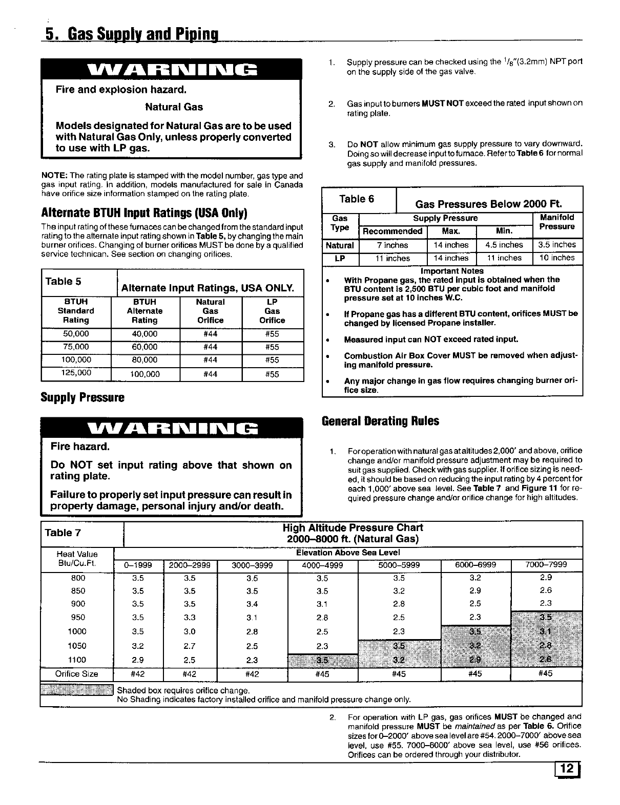
Alternate BTUHInput Ratings(USAOnly)
The input rating of these fu maces can be changed from the standard input
rating to the alternate input rating shown in Table 5, by changing the main
burner orifices. Changing of burner orifices MUST be done by a qualified
service technican. See section on changing orifices.
Table 5
STUH
Standard
Rating
50,000
75,000
100,000
125,000
Alternate Input Ratings, USA ONLY.
BTUH
Alternate
Rating
40,000
60,000
80,000
100,000
Natural LP
Gas Gas
Orifice Orifice
#44 #55
#44 #56
#44 #55
#44 #55
SupplyPressure
Fire hazard.
2. Gas input to burners MUST NOT exceed the rated input shown on
rating plate.
3. Do NOT allow minimum gas supply pressure to vary downward.
Doing so will decrease input to furnace. Refer to Table 6for normal
gas supply and manifold pressures.
Table 6
Gas
Type
Natural
LP
Gas Pressures Below 2000 Ft.
Supply Pressure Manifold
Recommended Max. Min. Pressure
7inches 14 inches 4.5 inches 3.5 inches
11 inches 14 inches 11 inches 10 inches
Important Notes
With Propane gas, the rated input is obtained when the
BTU content is 2,500 BTU per cubic toot and manifold
pressure set at 10 inches W.C.
If Propane gas has a different BTU content, orifices MUST be
changed by licensed Propane installer.
Measured input can NOT exceed rated input.
Combustion Air Box Cover MUST be removed when adjust-
ing manifold pressure.
Any major change in gas flow requires changing burner ori-
fice size.
GeneralDeratingRules
Do NOT set input rating above that shown on
rating plate.
Failure to properly set input pressure can result in
property damage, personal injury and/or death.
1. For operation with natural gas at altitudes 2,000' and above, orifice
change and/or manifold pressure adjustment may be required to
suit gas supplied. Check with gas supplier. If orifice sizing is need-
ed, it should be based on reducing the input rating by 4 percent for
each 1,000" above sea level. See Table 7 and Figure 11 for re-
quired pressure change and/or orifice change for high altitudes.
Table 7
Heat Value
Btu/Cu.Ft.
8OO
85O
9OO
95O
1000
1050
1100
Orifice Size
0-1999
3.5
3.5
3.5
3.5
3.5
3.2
2.9
#42
2000-2999
3.5
3.5
3.5
3.3
3.0
2.7
2.5
#42
3000-3999
3.5
3.5
3.4
3.1
2.8
2.5
2.3
#42
High Altitude Pressure Chart
2000-8000 ft. (Natural Gas)
Elevation Above Sea Level
4000-4999
3.5
3.5
3.1
2.8
2.5
2.3
#45
5000-5999 6000_999
3.5 3.2
3.2 2.9
2.8 2.5
2.5 2.3
2.9
#45 #45
7000-7999
2.9
2.6
2.3
#45
Shaded box requires orifice change.
No Shading indicates factory installed orifice and manifold pressure change only.
2. For operation with LP gas, gas orifices MUST be changed and
manifold pressure MUST be maintained as per Table 6. Orifice
sizes for 0-2000" above sea level are #54. 2000-7000" above sea
level, use #55. 7000-8000" above sea level, use #56 orifices.
Orifices can be ordered through your distributor.
Manifold GasPressureAdjustment
NOTE: Gas supply pressure MUST be within minimum and maximum vaF
ues listed on rating plate. Pressures are usually set by gas suppliers.
Make adjustment to manifold pressure with burners operating and com-
bustion air box cover removed.
1. Remove combustion air box cover.
2. Connect U-Tube manometer to the tapped opening on the outlet
side of gas valve. Use manometer with a0-min.12" water column
range.
3. Turn gas ON, fire the furnace and remove adjustment screw cover
on gas valve.
4, Turn counterclockwise to decrease pressure and clockwise to in-
crease.
5. Set pressure to value shown inTable 6. Refer to Important Notes
in Table 6. Pressure is also listed on furnace rating plate.
6. When pressure is set, replace adjustment screw cover on gas
valve.
7. Replace combustion air box cover.
NOTE: Adjustment screw cover MUST be replaced on gas valve BE-
FORE reading manifold pressure and operating furnace.
HighAltitude Air PressureSwitch
Altitudes over 4,000' require a different air pressure switch than the one
installed at the factory. Check parts list for pressure switch and consult
your distributor for part number and availability. In Canada, provincial
codes may govern installation of switch. Check with gove rning authorities.
ChangingOrificesfor HighAltitude
Electrical shock, fire or explosion hazard.
Turn OFF electric power (at disconnect) and gas
supply (at manual valve in gas line) when
installing orifices. Installation of orifices requires
a qualified service technician.
Failure to properly install orifices can result in
property damage, personal injury and/or death.
NOTE: Main burner orifices can be changed for high altitudes.
1. Disconnect gas line from gas valve.
2. Remove combustion box front cover and manifold from furnace.
3. Remove the orifices from the manifold and replace them with prop-
erly sized orifices.
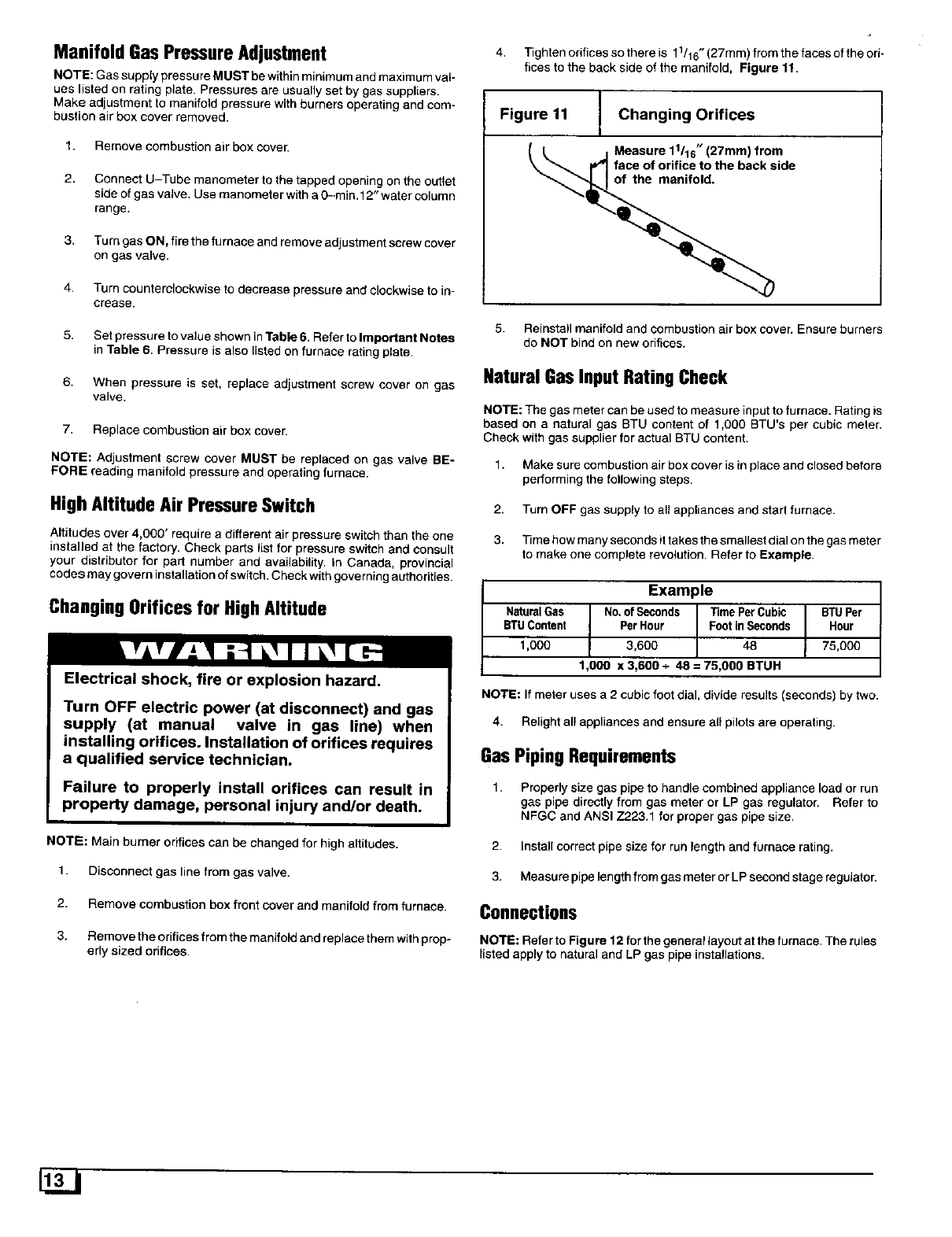
4. Tighten orifices so there is 11/16"(27mm) from the faces of the ori-
rices to the back side of the manifold, Figure 11.
Figure 11 Changing Orifices
Measure 11116,, (27mm) from
face of orifice to the back side
of the manifold.
5. Reinstall manifold and combustion air box cover. Ensure burners
do NOT bind on new orifices.
Natural Gas Input Rating Check
NOTE: The gas meter can be used to measure input to furnace. Rating is
based on a natural gas BTU content of 1,000 BTU's per cubic meter.
Check with gas supplier for actual BTU content.
1. Make sure combustion air box cover is in place and closed before
performing the following steps.
2. Turn OFF gas supply to all appliances and start furnace.
3. Time how many seconds it takes the smallest dial on the gas meter
to make one complete revolution. Refer to Example.
Example
NaturalGas | No.of Seconds Time PerCubic BTUPer
BTUContent tPerHour Footin Seconds Hour1,000 3,600 48 75,000
1,000 x 3,600 +48 = 75,000 BTUH
NOTE: If meter uses a 2 cubic foot dial, divide results (seconds) by two.
4. Relight all appliances and ensure all pilots are operating.
GasPipingRequirements
1. Properly size gas pipe to handle combined appliance load or run
gas pipe directly from gas meter or LP gas regulator. Refer to
NFGC and ANSI Z223.1 for proper gas pipe size.
2. Install correct pipe size for run length and furnace rating.
3. Measure pipe length from gas meter or LP second stage regulator.
Connections
NOTE: Refer to Figure 12 for the general layout at the furnace. The rules
listed apply to natural and LP gas pipe installations.
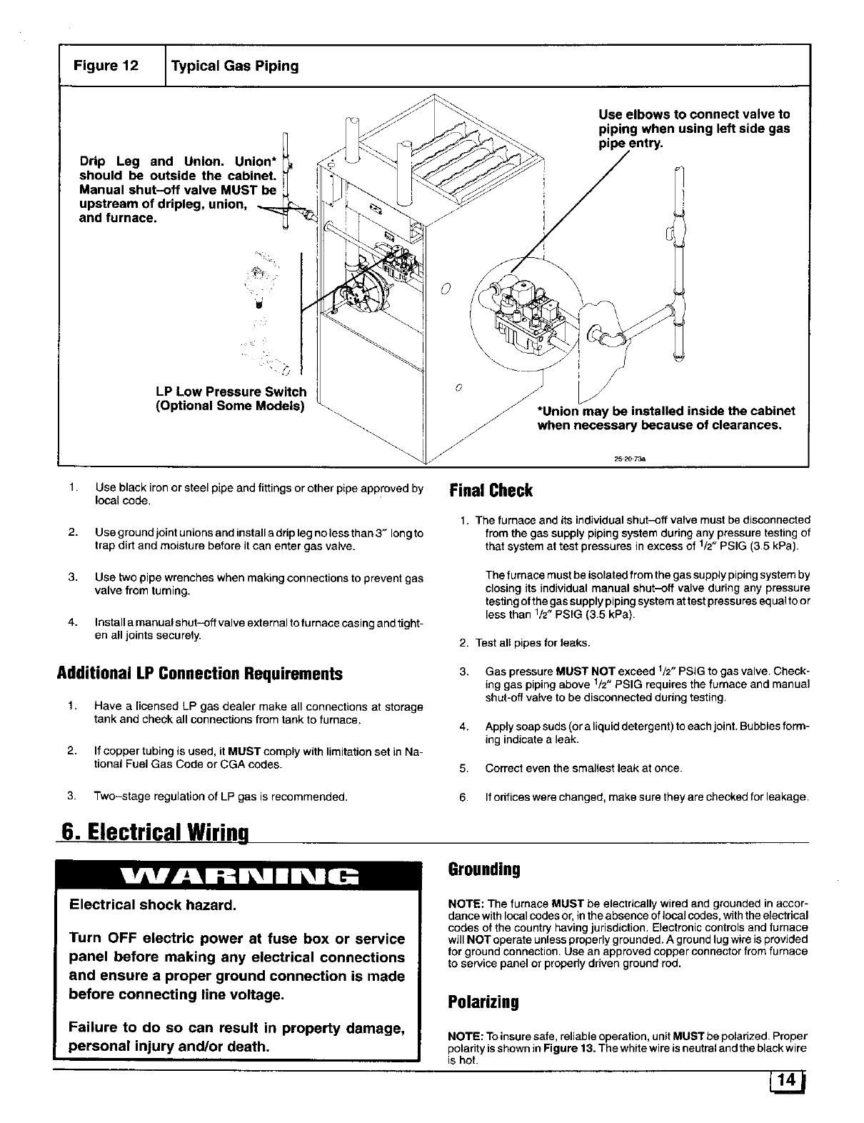
Figure 12 _Typical Gas Piping
Drip Leg and Union. Union*
should be outside the cabinet.
Manual shut-off valve MUST be
upstream of dripleg, union,
and furnace.
Use elbows to connect valve to
piping when using left side gas
pipe
a _
LP Low Pressure Switch
(Optional Some Models)
\
*Union may be installed inside the cabinet
when necessary because of clearances.
1.
2.
Use black iron or steel pipe and fittings or other pipe approved by
local code.
Use ground joint unions and install a drip leg no less than 3" long to
trap dirt and moisture before it can enter gas valve.
Final Check
1. The furnace and its individual shut-off valve must be disconnected
from the gas supply piping system during any pressure testing of
that system at test pressures in excess of 1/2" PSIG (3.5 kPa).
3.
4.
Use two pipe wrenches when making connections to prevent gas
valve from turning.
Install a manual shut-off valve external to fumace casing and tight-
en all joints securely.
The furnace must be isolated from the gas supply piping system by
closing its individual manual shut-off valve during any pressure
testing of the gas supply piping system at test pressures equal to or
less than 1/2" PSIG (3.5 kPa).
2. Test all pipes for leaks.
Additional LP ConnectionRequirements
1. Have a [icensed LP gas dealer make all connections at storage
tank and check all connections from tank to furnace.
2. If copper tubing is used, it MUST comply with limitation set in Na-
tional Fuel Gas Code or CGA codes.
3,
4.
5.
Gas pressure MUST NOT exceed 1/2" PSIG to gas valve. Check-
ing gas piping above 1/2" PSIG requires the furnace and manual
shut-off valve to be disconnected during testing.
Apply soap suds (or a liquid detergent) to each joint. Bubbles form-
ing indicate a leak.
Correct even the smallest leak at once.
3. Two-stage regulation of LP gas is recommended. 6. If odfices were changed, make sure they are checked for leakage•
6. Electrical Wiring
Electrical shock hazard.
Grounding
Turn OFF electric power at fuse box or service
panel before making any electrical connections
and ensure a proper ground connection is made
before connecting line voltage.
Failure to do so can result in property damage,
personal injury and/or death.
NOTE: The furnace MUST be electrically wired and grounded in accor-
dance with local codes or, in the absence of IocaJ codes, with the electrical
codes of the country having jurisdiction. Electronic controls and furnace
will NOT operate unless properly grounded. A ground lug wire is provided
for ground connection. Use an approved copper connector from furnace
to service panel or properly driven ground rod.
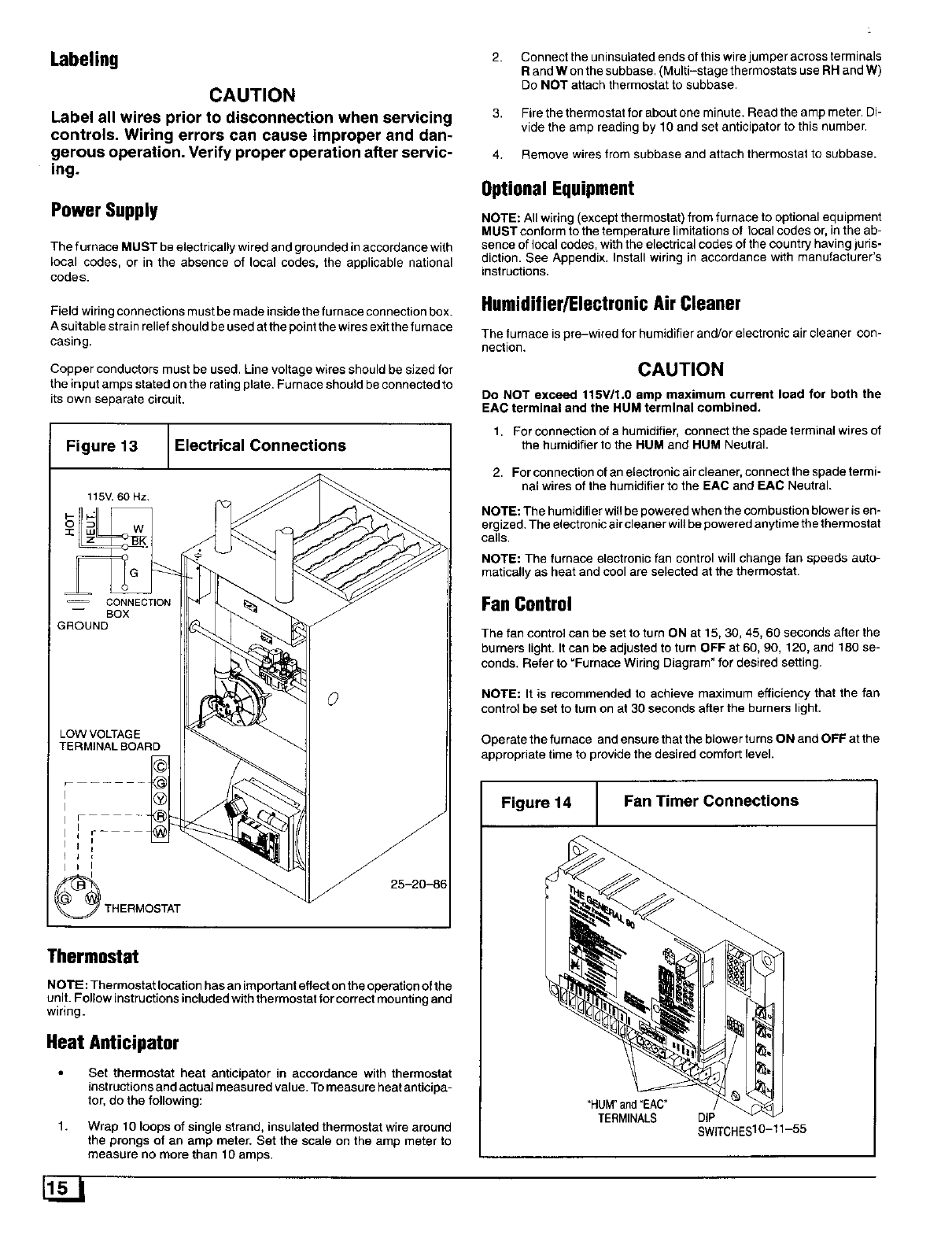
Polarizing
NOTE: To insure safe, reliable operation, unit MUST be polarized. Proper
polarity is shown in Figure 13. The white wire is neutral and the black wire
is hot.
Labeling
CAUTION
Label all wires prior to disconnection when servicing
controls. Wiring errors can cause improper and dan-
gerous operation. Verify proper operation after servic-
ing.
Power Supply
The furnace MUST be electrically wired and grounded in accordance with
local codes, or in the absence of local codes, the applicable national
codes.
Field wiring connections must be made inside the furnace connection box.
A suitable strain relief should be used at the point the wires exit the furnace
casing.
Copper conductors must be used. Line voltage wires should be sized for
the input amps stated on the rating plate. Furnace should be connected to
its own separate circuit.
Figure 13 _Electrical Connections
115V.60 Hz.
sg
Iul
z
G _;
-- CONNECTION
GROUNDBOX
LOW VOLTAGE
TERMINAL BOARD
F
t I
25-20-86
Thermostat
NOTE: Thermostat location has an important effect on the operation of the
unit. Follow instructions included with thermostat for correct mounting and
wiring.
Heat Anticipator
Set thermostat heat anticipator in accordance with thermostat
instructions and actual measured value. To measure heat anticipa-
tor, do the following:
1. Wrap 10 loops of single strand, insulated thermostat wire around
the prongs of an amp meter. Set the scale on the amp meter to
measure no more than 10 amps.
2.
3.
4.
Connect the uninsulated ends of this wire jumper across terminals
Rand Won the subbase. (Multi-stage thermostats use RH and W)
Do NOT attach thermostat to subbase.
Fire the thermostat for about one minute. Read the amp meter. Di-
vide the amp reading by 10 and set anticipator to this number.
Remove wires from subbase and attach thermostat to subbase.
Optional Equipment
NOTE: All wiring (except thermostat) from furnace to optional equipment
MUST conform to the temperature limitations of local codes or, in the ab-
sence of local codes, with the electrical codes of the country having juris-
diction. See Appendix. Install wiring in accordance with manufacturer's
instructions.
Humidifier/ElectronicAirCleaner
The furnace is pre-wired for humidifier and/or electronic air cleaner con-
nection.
CAUTION
Do NOT exceed 115VI1.0 amp maximum current load for both the
EAC terminal and the HUM terminal combined.
1. For connection of a humidifier, connect the spade terminal wires of
the humidifier to the HUM and HUM Neutral.
2. For connection of an electronic air cleaner, connect the spade termi-
nal wires of the humidifier to the EAC and EAC Neutral.
NOTE: The humidifier will be powered when the combustion blower is em
ergized. The electronic air cleaner will be powered anyti me the thermostat
calls.
NOTE: The furnace electronic fan control will change fan speeds auto-
matically as heat and cool are selected at the thermostat.
Fan Control
The fan control can be set to turn ON at 15, 30, 45, 60 seconds after the
burners light, It can be adjusted to turn OFF at 60, 90, 120, and 180 se-
conds. Refer to "Furnace Wiring Diagram" for desired setting.
NOTE: It is recommended to achieve maximum efficiency that the fan
control be set to turn on at 30 seconds after the burners light.
Operate the furnace and ensure that the blower turns ON and OFF at the
appropriate time to provide the desired comfort level.
Figure 14 Fan Timer Connections
"HUM"and "EAC"
TERMINALS DIP
SWITCHES10-11-55
7. DuctworkandFilter
Carbon monoxide poisoning hazard.
Do NOT draw return air from inside a closet or util-
ity room, Return air duct MUST be sealed to fur-
nace casing.
Failure to properly seal duct can result in personal
injury and/or death,
Instailation
NOTE: Design and install air distribution system to comply with Air Condi-
tioning Contractors of America manuals and/or NFPA pamphlets 90A and
90B or other approved methods that conform to local codes and good
trade practices.
1. When furnace supply ducts carry air outside furnace area, seal re-
turn air ducl to furnace casing and terminate duct outside furnace
space.
2,
3.
4,
install air conditioning cooling coil (evaporator) on outlet side of fur-
nace.
For fu maces installed without acooling coil it is recommended that
the outlet duct be provided with a removable access panel. This
panel should be accessible when the furnace is installed so the
exterior of the heat exchanger can be viewed for inspections.The
access panel MUST be sealed to prevent leaks.
If separate evaporator and blower units are used, install good seal-
ing dampers for air flow control Chilled air going through the fur-
nace could cause condensation and shorten the furnace life.
NOTE: Dampers (field supplied) can be either automatic or manual.
Manually operated dampers MUST be equipped with a means to prevent
furnace or air conditioning operation unless damper is in the full heat or
cool position.
Carbon monoxide poisoning hazard.
Cool air passing over heat exchanger can
cause condensate to form resulting in heat ex-
changer failure.
This could result in personal injury and/or
death.
Connections
NOTE: Return air can enter through either side, both sides, or the bottom.
Return air _ enter through rear of the furnace. When the furnace is
located in an area near or adjacent to the living area, the system should be
carefully designed with returns to minimize noise transmission through
the return grille. Any blower moving a high volume of air will produce audi-
ble noise which could be objectionable to when the unit is located very
close to living areas. It is advisable to route the return air ducts under the
floor or through the attic.
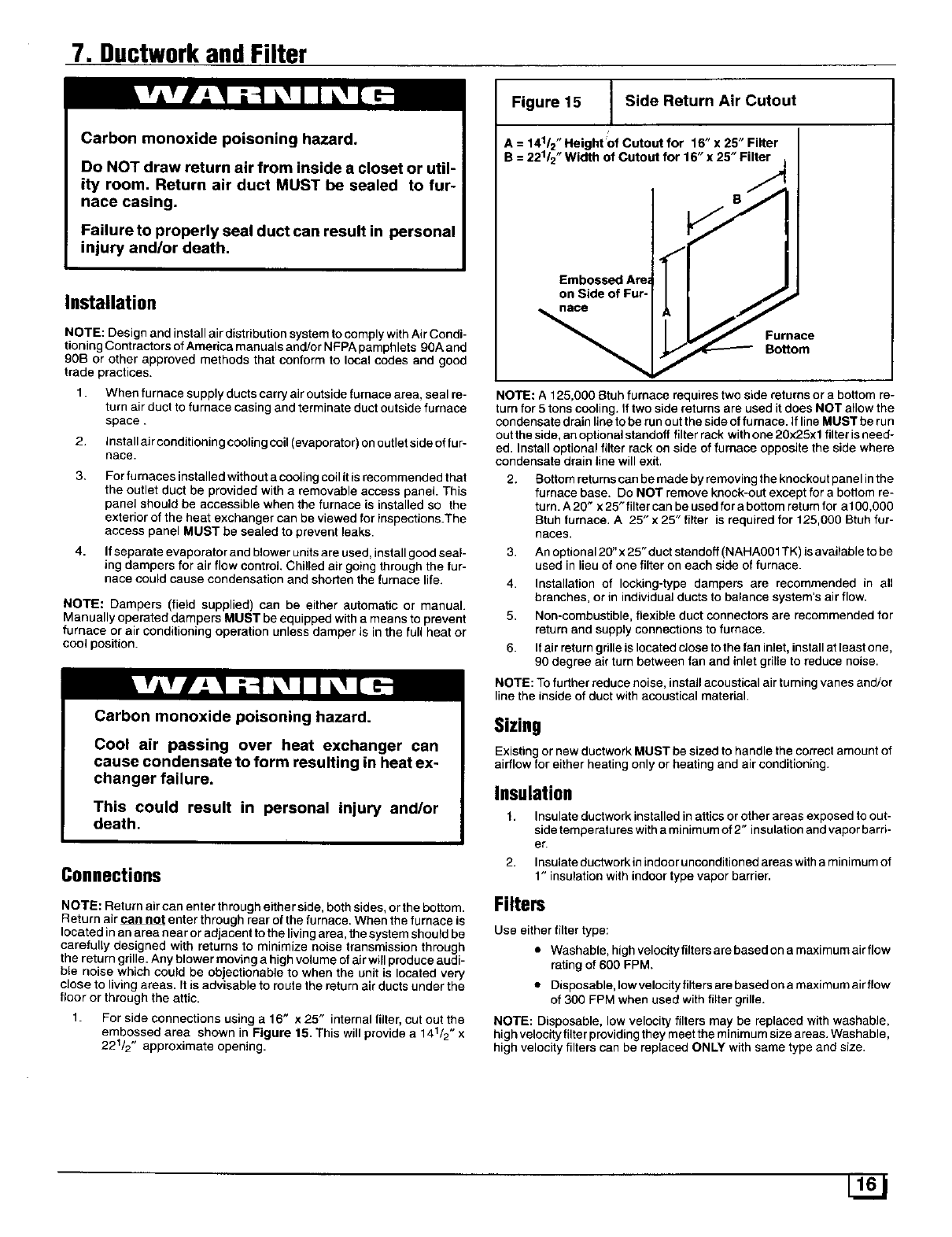
1. For side connections using a 16" x 25" internal filter, cut out the
embossed area shown in Figure t5. This will provide a 141/2" x
221/2 " approximate opening.
Figure 15 Side Return Air Cutout
A = 141/2" Height Of cutout for 16" x 2,5"Filter
B = 221/2" Width of Cutout for 16" x 25" Filter j
//,
Embossed Are_ i
on Side of Fur- .,/_ _,,
l//Furnace
Bottom
NOTE: A 125,000 8tuh furnace requires two side returns or a bottom re-
turn for 5 tons cooling. If two side returns are used it does NOT allow the
condensate drain line to be run out the side of furnace, if line MUST be run
out the side, an optional standoff filter rack with one 20x25x 1 filter is need-
ed. Install optional filter rack on side of furnace opposite the side where
condensate drain line will exit.
2, Bottom returns can be made by removing the knockout panel in the
furnace base. Do NOT remove knock-out except for a bottom re-
turn. A 20" x 25" filter can be used for a bottom return for a 100,000
8tub furnace, A 25" x 25" filter is required for 125,000 Btuh fur-
Races.
3. An optional 20" x 25" duct standoff (NAHA001TK) is available to be
used in lieu of one filter on each side of furnace.
4. Installation of locking-type dampers are recommended in all
branches, or in individual ducts to balance system's air flow.
5. Non-combustible, flexible duct connectors are recommended for
return and supply connections to furnace.
6. If air return grille is located close to the fan inlet, install at least one,
90 degree air turn between fan and inlet grille to reduce noise.
NOTE: To further reduce noise, install acoustical air turning vanes and/or
line the inside of duct with acoustical material.
Sizing
Existing or new ductwork MUST be sized to handle the correct amount of
airflow for either heating only or heating and air conditioning.
Insulation
1. Insulate ductwork installed in attics or other areas exposed to out-
side temperatures with a minimum of 2" insulation and vapor barri-
er.
2. Insulate ductworkin indoor unconditioned areas with a minimum of
1" insulation with indoor type vapor barrier.
Filters
Use either filter type:
• Washable, high velocity filters are based on a maximum air flow
rating of 600 FPM.
•Disposable, lowvelocityfiltersarebesedonamaximumairflow
of 300 FPM when used with filter grille.
NOTE: Disposable, low velocity filters may be replaced with washabJe,
high velocity filter providing they meet the minimum size areas. Washable,
high velocity filters can be replaced ONLY with same type and size.
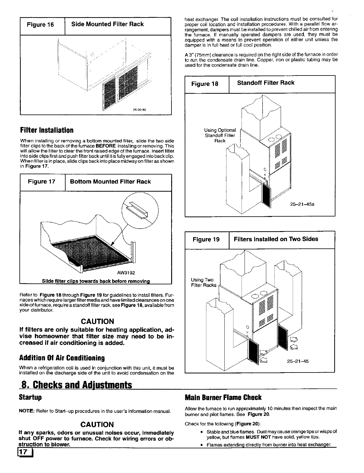
Figure 16 Side Mounted Filter Rack
i •
I •
Filter Installation
When installing or removing a bottom mounted filter, slide the two side
filter clips to the back of the furnace BEFORE installing or removing. This
will allow the filter to clear the front raised edge of the furnace. Insert filter
into side clips first and push filter back until it is fully engaged into back clip.
When filter is in pl ace, slide clips back into place midway on filter as shown
in Figure 17.
Figure 17 _J Bottom Mounted Filter Rack
AW3192
Slide filter clips towards back before removing
Refer to Figure 18 through Figure 19 for guidelines to install filters. Fur-
naces which require larger filter media and have fimited clearances on one
side of furnace, require astandoff filter rack, see Fig ure 18, available from
your distributor.
CAUTION
If filters are only suitable for heating application, ad-
vise homeowner that filter size may need to be in-
creased if air conditioning is added.
Addition Of Air Conditioning
When a refrigeration coU is used in conjunction with this unit, it must be
installed on the discharge side of the unit to avoid condensation on the
heat exchanger• The coil installation instructions must be consulted for
proper coil location and installation procedures. With a parallel flow ar-
rangement, dampers must be installed to prevent chilled air from entering
the furnace. If manually operated dampers are used, they must be
equipped with a means to prevent operation of either unit unless the
damper is in full heat or full cool position.
A 3" (75mm) clearance is required on the right side of the furnace in order
to run the condensate drain line. Copper, iron or plastic tubing may be
used for the condensate drain line.
Figure 18 Standoff Filter Rack
Using Optional _ F
Standoff Filter I_ J _'_
Rack I _ _ _ __
_25-21-45a
Figure 19 Filters Installed on Two Sides
Using Two _ "__'_
Filter Racks _ _
8. ChecksandAdjustments
Startup Main BurnerFlameCheck
NOTE: Refer to Start-up procedures in the user's information manual•
CAUTION
If any sparks, odors or unusual noises occur, immediately
shut OFF power to furnace. Check for wiring errors or ob-
struction to blower.
Allow the furnace to run approximately 10 minutes then inspect the main
burner and pilot flames. See Figure 20.
Check for the following (Figure 20):
•Stable and blue flames. Dust may cause orange tipsor wisps of
yellow, but flames MUST NOT have solid, yellow tips.
•Flames extendin9 directly from burner into heat exchanqer,
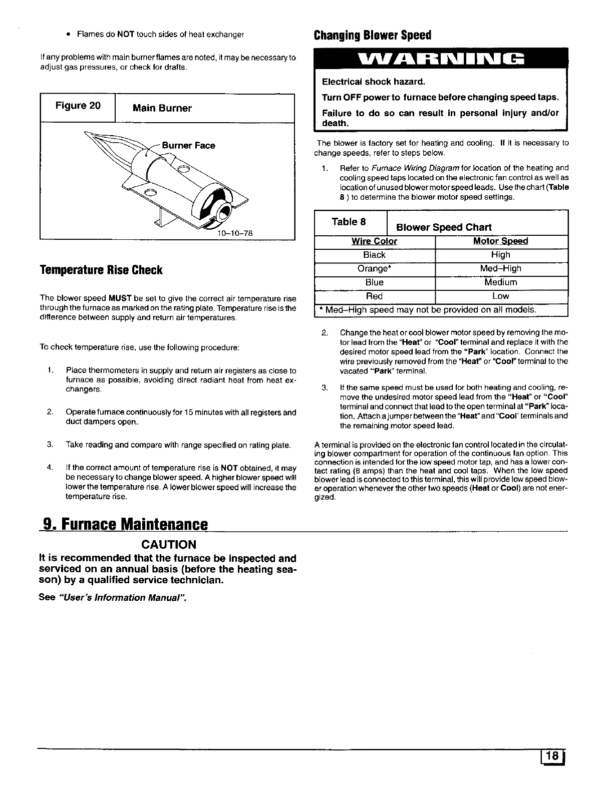
•Flames do NOT touch sides of heat exchanger ChangingBlowerSpeed
If any problems with main burner flames are noted, it may be necessary to
adjust gas pressures, or check for drafts.
Figure 20 Main Burner
10-10-78
TemperatureRiseCheck
The blower speed MUST be set to give the correct air temperature rise
through the furnace as marked on the rating plate. Temperature rise is the
difference between supply and return air temperatures.
To check temperature rise, use the following procedure:
1. Place thermometers in supply and return air registers as close to
furnace as possible, avoiding direct radiant heat from heat ex-
changers.
2. Operate furnace continuously for 15 minutes with all registers and
duct dampers open.
The blower is factory set for heating and cooling. If it is necessary to
change speeds, refer to steps below.
1. Refer to Furnace Wiring Diagram for location of the heating and
cooling speed taps located on the electronic fan control as well as
location of unused blower motor speed leads. Use the chart (Table
8 ) to determine the blower motor speed settings.
Table 8
Wire Color
Black
Orange*
Blue
Red
Blower Speed Chart
Motor Speed
High
Med-High
Medium
Low
*Meal-High speed may not be provided on all models.
2.
3.
Change the heat or cool blower motor speed by removing the mo-
tor lead from the "Heat" or "Cool" terminal and replace it with the
desired motor speed lead from the "Park" location. Connect the
wire previously removed from the "Heat" or "Coor' terminal to the
vacated "Park" terminal.
If the same speed must be used for both heating and cooling, re-
move the undesired motor speed lead from the "Heat" or "Cool"
terminal and connect that lead to the open terminal at "Park" loca-
tion. Attach a jumper between the"Heat" and"Cool" terminals and
the remaining motor speed lead.
3,
4.
Take reading and compare with range specified on rating plate.
If the correct amount of temperature rise is NOT obtained, it may
be necessary to change blower speed. A higher blower speed will
lower the temperature rise. A lower blower speed will increase the
temperature rise.
A terminal is provided on the electronic fan control located in the circulat-
ing blower compartment for operation of the continuous fan option. This
connection is intended for the low speed motor tap, and has a lower con-
tact rating (8 amps) than the heat and cool taps. When the low speed
blower lead isconnected to this terminal, this will provide low speed blow-
er operation whenever the other two speeds (Heat or Cool) are not ener-
gized.
9. FurnaceMaintenance
CAUTION
It is recommended that the furnace be inspected and
serviced on an annual basis (before the heating sea-
son) by a qualified service technician.
See "User's Information Manual"
