ICP Evaporator Coils Manual L0604333
User Manual: ICP ICP Evaporator Coils Manual ICP Evaporator Coils Owner's Manual, ICP Evaporator Coils installation guides
Open the PDF directly: View PDF ![]() .
.
Page Count: 7

Theseinstructionsmustbereadandunderstoodcompletelybeforeattemptinginstallation.
It is important that the Blower and Duct System be properly sized to allow the system to operate at full capacity. Poorly
designed systems will not give satisfactory cooling or economy, They may even shorten the service life of the compres-
sor in the outdoor unit,
Safety Labeling and Signal Words
DANGER, WARNING, CAUTION, and
NOTE
The signal words DANGER, WARNING, CAU-
TION, and NOTE are used to identify levels of haz-
ard seriousness. The signal word DANGER is only
used on product labels to signify an immediate haz-
ard. The signal words WARNING, CAUTION, and
NOTE will be used on product labels and through-
out this manual and other manuals that may apply
to the product.
DANGER - Immediate hazards which will result in
severe personal injury or death.
WARNING - Hazards or unsafe practices which
could result in severe personal injury or death.
CAUTION - Hazards or unsafe practices which
may result in minor personal injury or product or
property damage.
NOTE - Used to highlight suggestions which will
result in enhanced installation, reliability, or opera-
tion.
Signal Words in Manuals
The signal word WARNING is used throughout this
manual in the following manner:
The signal word CAUTION is used throughout this
manual in the following manner:
Signal Words on Product Labeling
Signal words are used in combination with colors
and/or pictures on product labels,
TABLE OF CONTENTS
Installation .................................. 2 - 3
Refrigerant Line Connections .................... 3
Refrigerant Metering Device ..................... 4
Condensate Drain .............................. 4
Waste Line Connection .......................... 4
Check and Adjust Airflow ........................ 5
Start-Up Procedure ............................ 5
Airflow vs. CFM Chart ........................... 6
R-410A Quick Reference Guide .................. 7
ELECTRICAL SHOCK HAZARD
Failure to turn off electric power could result in
personal injury or death.
Before installing or servicing system, turn off
main power to the system. There may be more than
one disconnect switch, including accessory heat-
er(s).
484 01 3100 00 January 2006
INSTALLATION
EHD Coils are designed to be used for air conditioning or
heat pump operation within horizontal runs of HVAC duct-
work. The ductwork may be a new or existing system, as-
sociated with a furnace, air handler, blower cabinet, or
other air moving device. Air can flow in either direction
through the coil.
Verify that the ductwork is suitable for cooling operation.
Externally insulated ductwork must have an adequate va-
por barrier. The vapor barrier prevents condensation from
forming in the insulating material, which would result in
loss of insulating value and deterioration of the insulation
material.
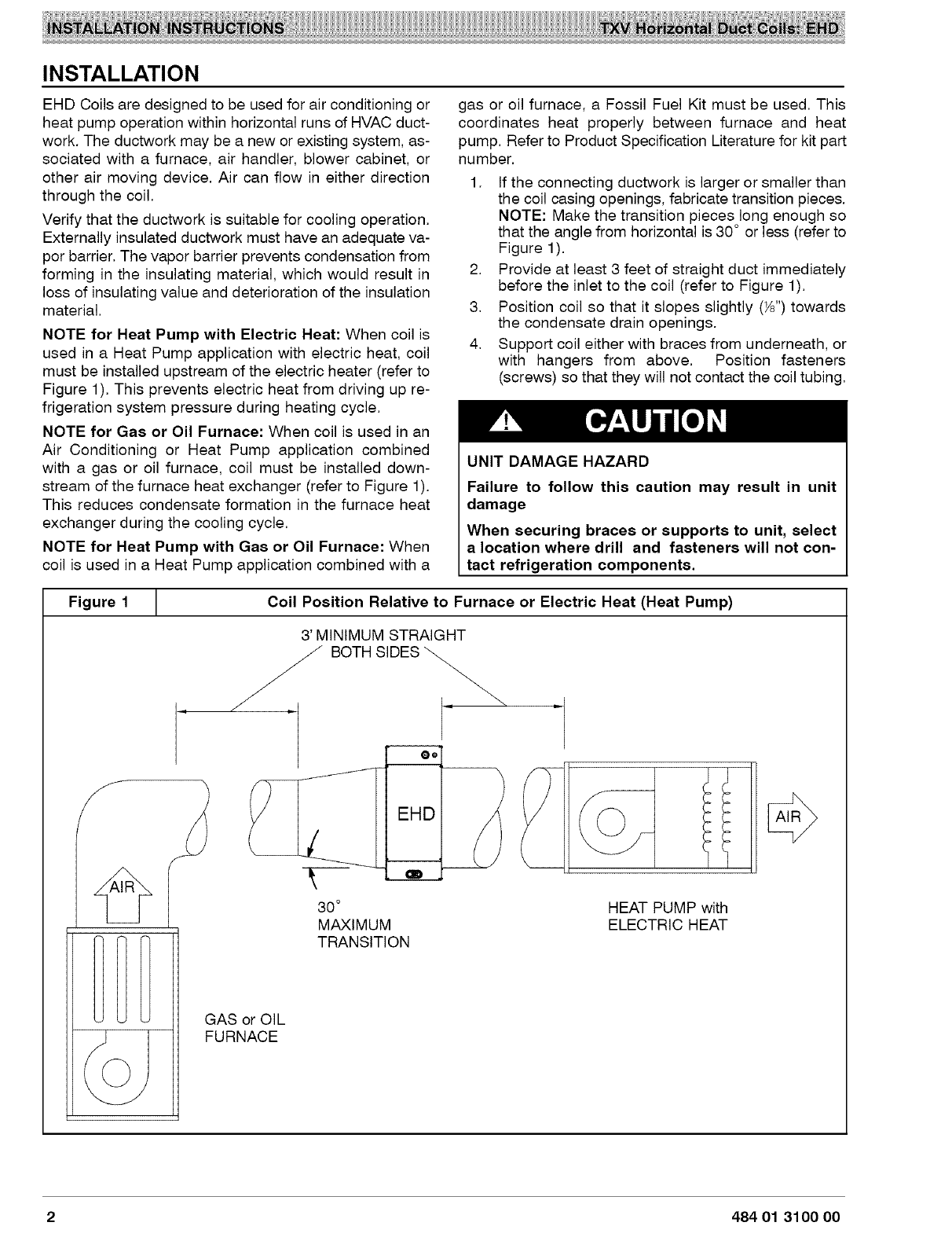
NOTE for Heat Pump with Electric Heat: When coil is
used in a Heat Pump application with electric heat, coil
must be installed upstream of the electric heater (refer to
Figure 1). This prevents electric heat from driving up re-
frigeration system pressure during heating cycle.
NOTE for Gas or Oil Furnace: When coil is used in an
Air Conditioning or Heat Pump application combined
with a gas or oil furnace, coil must be installed down-
stream of the furnace heat exchanger (refer to Figure 1).
This reduces condensate formation in the furnace heat
exchanger during the cooling cycle.
NOTE for Heat Pump with Gas or Oil Furnace: When
coil is used in a Heat Pump application combined with a
gas or oil furnace, a Fossil Fuel Kit must be used. This
coordinates heat properly between furnace and heat
pump. Refer to Product Specification Literature for kit part
number.
1. If the connecting ductwork is larger or smaller than
the coil casing openings, fabricate transition pieces.
NOTE: Make the transition pieces long enough so
that the angle from horizontal is 30 ° or less (refer to
Figure 1).
2. Provide at least 3 feet of straight duct immediately
before the inlet to the coil (refer to Figure 1).
3. Position coil so that it slopes slightly (Ys")towards
the condensate drain openings.
4. Support coil either with braces from underneath, or
with hangers from above. Position fasteners
(screws) so that they will not contact the coil tubing.
UNIT DAMAGE HAZARD
Failure to follow this caution may result in unit
damage
When securing braces or supports to unit, select
a location where drill and fasteners will not con-
tact refrigeration components.
Figure 1
Y
Coil Position Relative to Furnace or Electric Heat (Heat Pump)
3' MINIMUM STRAIGHT
BOTH SIDES
@®
EHD
30°
MAXIMUM
TRANSITION
HEAT PUMP with
ELECTRIC HEAT
GAS or OIL
FURNACE
2 484 01 3100 00

PROPERTY DAMAGE HAZARD
Failure to follow this caution may result in proper-
ty damage
A field fabricated auxiliary drain pan, with a sepa-
rate drain is REQUIRED for all installations over a
finished living space or in any area that may be
damaged by overflow from a restricted main drain
pan.
REFRIGERANT LINE CONNECTIONS
PERSONALINJURY HAZARD
Failure to relieve pressure in the coil could result
in personal injury.
Wear eye protection.
Coil is factory charged with 15 psi nitrogen. Pierce
the centers of both rubber tubing plugs to relieve
pressure before removing plugs.
NOTE: Factory nitrogen charge may escape past rubber
plugs during storage. This does not indicate a leaking coil
nor warrant return of the coil.
Size and install refrigerant lines according to information
provided with outdoor unit. Coil connection tube sizes are
shown in Figure 2. Route refrigerant lines to the coil in a
manner that will not obstruct service access to the unit.
1. Slide tubing cover plate onto the refrigerant lines
(field line-set), away from braze joints.
2. Remove rubber plugs from coil stubs using a pulling
and twisting motion. Hold coil stubs steady to avoid
bending or distorting.
3. Wrap TXV and nearby tubing with a heat-sinking
material such as a wet cloth.
4. Fit refrigerant lines into coil stubs. Wrap a heat sink-
ing material such as a wet cloth behind braze joints.
NOTE: See outdoor unit Installation Instructions re-
garding requirements for installation of a filter-drier
in the liquid line close to the indoor coil.
5. Braze using a SiI-Fos or Phos-copper alloy.
6. After brazing, allow joints to cool. Slide tubing cover
plate over joints.
Figure 2Coil Connection Tube Size (inch)
Model Size Liquid Suction
24 (2 ton) 3/8 5/8
30 (2Y2 ton) 3/8 3A
36 (3 ton) 3/8 3A
42 (3Y2 ton) 3/8 7/8
48 (4 ton) 3/8 7/8
60 (5 ton) 3/8 7/8
Figure 3 J EHD Coil (end view)
Tubing Cover Plate -_
OO
-Oe
0 0
Secondary Drain
(smaller opening) Primary Drain
(larger opening)
484 01 3100 00 3
REFRIGERANT METERING DEVICE
EHD2X coils have a factory installed hard shut-off TXV
designed only for use with R-22 refrigerant. Use only with
outdoor units designed for R-22.
EHD4X coils have a factory installed hard shut-off TXV
designed only for use with R-410A refrigerant. Use only
with outdoor units designed for R-410A.
TXV is factory set and not field adjustable.
CONDENSATE DRAIN
Coil is provided with two 3_,,NPT condensate drain con-
nections. The connection with the larger internal open-
ing is the primary drain, and the connection with the
smaller internal opening is the secondary (overflow)
drain (refer to Figure 3). Use PVC fittings on the plastic
condensate pan. Finger tighten plus 11/2turns. Do not
over-tighten. Use pipe dope.
If coil is located in or above a living space where damage
may result from condensate overflow, a separate 3_,,drain
must be provided from secondary (overflow) drain con-
nection. Run this drain to a place in compliance with local
installation codes where it will be noticed when unit is op-
erational. Condensate flowing from secondary (overflow)
drain indicates a plugged primary drain - unit requires
service or water damage will occur.
1. Connect drain lines to the appropriate drain connec-
tions. Drain lines should not be smaller than the
drain connections (3_,,).
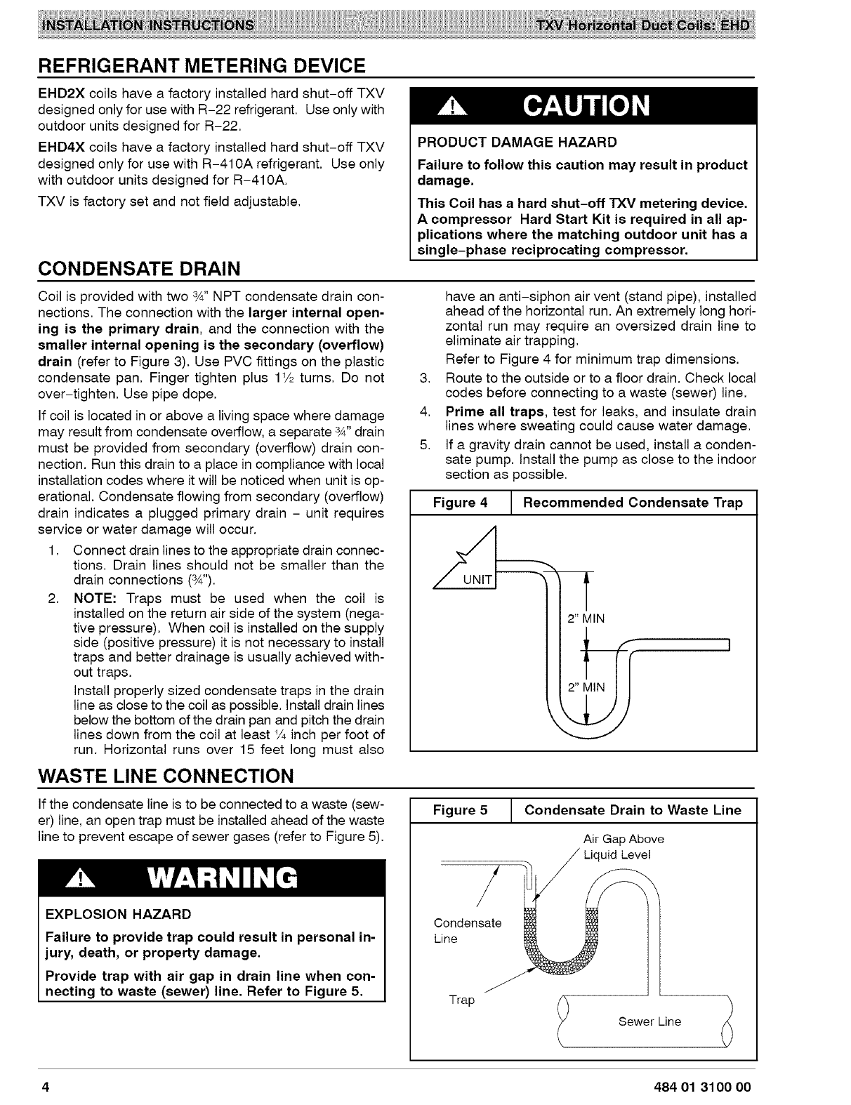
2. NOTE: Traps must be used when the coil is
installed on the return air side of the system (nega-
tive pressure). When coil is installed on the supply
side (positive pressure) it is not necessary to install
traps and better drainage is usually achieved with-
out traps.
Install properly sized condensate traps in the drain
line as close to the coil as possible. Install drain lines
below the bottom of the drain pan and pitch the drain
lines down from the coil at least ¼ inch per foot of
run. Horizontal runs over 15 feet long must also
WASTE LINE CONNECTION
PRODUCT DAMAGE HAZARD
Failure to follow this caution may result in product
damage.
This Coil has a hard shut-off TXV metering device.
A compressor Hard Start Kit is required in all ap-
plications where the matching outdoor unit has a
single-phase reciprocating compressor.
have an anti-siphon air vent (stand pipe), installed
ahead of the horizontal run. An extremely long hori-
zontal run may require an oversized drain line to
eliminate air trapping.
Refer to Figure 4 for minimum trap dimensions.
3. Route to the outside or to a floor drain. Check local
codes before connecting to a waste (sewer) line.
4. Prime all traps, test for leaks, and insulate drain
lines where sweating could cause water damage.
5. If a gravity drain cannot be used, install a conden-
sate pump. Install the pump as close to the indoor
section as possible.
J. Recommended Condensate Trap
Figure 4_
'
If the condensate line is to be connected to a waste (sew-
er) line, an open trap must be installed ahead of the waste
line to prevent escape of sewer gases (refer to Figure 5).
EXPLOSION HAZARD
Failure to provide trap could result in personal in-
jury, death, or property damage.
Provide trap with air gap in drain line when con-
necting to waste (sewer) line. Refer to Figure 5.
Figure 5
Condensate
Line
Trap
Condensate Drain to Waste Line
Air Gap Above
Liquid Level
l Sewer Line t
4 484 01 3100 00

CHECK AND ADJUST AIR FLOW
ELECTRICAL SHOCK HAZARD
Failure to shut of electric power could result in
personal injury or death.
Before adjusting blower speed, shut off electric
power to the furnace or blower module.
It is important that the correct amount of air (CFM) flows
through the coil. The installer must determine the re-
quired CFM based on the characteristics of the specific
system (such as system size, ducting, components, and
accessories). In general, 400 CFM per ton is the nominal
required value, with a range of 350 - 450 CFM per ton.
Check Static Pressure Drop and CFM Across Coil
The amount of air (CFM) is related to a pressure drop. To
determine the CFM, measure the pressure drop using an
inclined manometer (sometimes called draft gauge or air
flow gauge).
1. The coil should be dry and clean. The air filter must
be clean and in place. All registers open. DO NOT
run the outdoor unit when checking air flow.
2. Run the blower on cooling speed.
3. Using the manometer (draft gauge or flow gauge),
measure the static pressure drop across the dry coil
and compare it to the numbers in Figure 6.
4. Find the corresponding CFM in Figure 6.
Adjusting Air Flow
If CFM is too low, increase the blower speed and measure
the static pressure drop again. Determine CFM from Fig-
ure 6.
If CFM is too high, reduce the blower speed and measure
the static pressure drop again. Determine CFM from Fig-
ure 6.
NOTE: Change blower speed as shown in the instruc-
tions for the furnace or air handler.
NOTE: It may not be possible to obtain a gauge reading
exactly the same as shown in Figure 6. This is due to vari-
ations in duct systems and blower speeds.
If the motor is at the highest speed and the CFM is still not
high enough, replace the blower and/or motor with a larg-
er size.
If the unit has an adjustable belt driven blower, use an am-
meter to check the motor current draw. If the current draw
is higher than the motor name plate amps, replace the
motor with one of greater horsepower.
START-UP PROCEDURE
Refer to outdoor unit Installation Instructions for refrigera-
tion system start-up instructions and refrigerant charging
method details.
484 01 3100 00 5

Figure6
CFM
Coil Across
Size Coil
400
500
24 600
700
2 tons 800
900
1000
400
500
600
30 700
800
2Y2tons 900
1000
1100
1200
400
500
600
700
36 800
900
3 tons 1000
1100
1200
1300
1400
600
700
800
900
42 1000
1100
3Y2tons 1200
1300
1400
1500
1600
Static Pressure Drop Across
Coil
(Inches Water Column)
Dry
0.060
0,081
0.104
0,129
0.155
0,186
0.217
0,044
0.060
0,077
0,097
0,116
0.140
0,165
0.190
0,219
0,043
0,058
0,074
0,089
0,107
0,127
0,150
0,172
0,197
0,224
0,252
0,065
0,079
0,095
0,113
0,134
0,154
0,176
0,197
0,220
0,246
0,268
Wet
0.069
0,096
0,129
0,162
0,198
0,237
0,278
0,050
0,071
0,093
0,116
0,144
0,172
0,203
0,235
0,269
0.048
0,066
0,086
0,104
0,128
0,154
0,182
0,212
0,245
0,280
0,317
0,076
0,094
0,114
0,137
0,163
0,189
0,215
0,245
0,273
0,303
0,332
CFM and Pressure Drop
Coil
Size
48
4 tons
6O
5 tons
CFM
Across
Coil
6OO
7OO
8OO
9OO
1000
1100
1200
1300
1400
1500
1600
1700
1800
800
900
1000
1100
1200
1300
1400
1500
1600
1700
1800
1900
2000
2100
2200
Static Pressure Drop Across
Coil
(Inches Water Column)
Dry
0.063
0,076
0.091
0,105
0,121
0,138
0,157
0,175
0,195
0,217
0,238
0,260
0,284
0,051
0,060
0,069
0,079
0,090
0,101
0,113
0,125
0,138
0,153
0,165
0.180
0.195
0.211
0.227
Wet
0,080
0,101
0.123
0,149
0.175
0,206
0,215
0,231
0,261
0,291
0,325
0,361
0,394
0,063
0,076
0,089
0.102
0,118
0,135
0.155
0,175
0,193
0.214
0.235
0.258
0.279
0.302
0.325
6 484 01 3100 00

R-410A QUICK REFERENCE GUIDE
• R-410A refrigerant operates at 50% -70% higher pressures than R-22. Be sure that servicing equipment and
replacement components are designed to operate with R-410A.
• R-410A refrigerant cylinders are rose colored.
• Recovery cylinder service pressure rating must be 400 psig, DOT 4BA400 or DOT BW400.
• R-410A systems should be charged with liquid refrigerant. Use a commercial type metering device in the
manifold hose.
• Manifold sets should be 750 psig high-side and 200 psig low-side with 520 psig low-side retard.
• Use hoses with 750 psig service pressure rating.
• Leak detectors should be designed to detect HFC refrigerant.
• R-410A, as with other HFC refrigerants, is only compatible with POE oils.
• POE oils absorb moisture rapidly. Do not expose oil to atmosphere.
• POE oils may cause damage to certain plastics and roofing materials.
• Vacuum pumps will not remove moisture from oil.
• A liquid line filter-drier is required on every unit.
• Do not use liquid line filter-driers with rated working pressures less than 600 psig.
• Do not install a suction line filter-drier in liquid line.
• Wrap all filter-driers and service valves with wet cloth when brazing.
• Do not use with an R-22 TXV.
• If indoor unit is equipped with an R-22 TXV, it must be changed to an R-410A TXV.
• Do not use capillary tube indoor coils.
• Never open system to atmosphere while it is under a vacuum.
• When system must be opened for service, break vacuum with dry nitrogen and replace all filter-driers.
• Do not vent R-410A into the atmosphere.
• Observe all WARNINGS, CAUTIONS, NOTES, and bold text.
484 01 3100 00 7
