ICP Controls And HVAC Accessories Manual L0909202
User Manual: ICP ICP Controls and HVAC Accessories Manual ICP Controls and HVAC Accessories Owner's Manual, ICP Controls and HVAC Accessories installation guides
Open the PDF directly: View PDF ![]() .
.
Page Count: 3
Installation Instructions For Flue Discharge Deflector Kit
(Kit Part No. NRFLUEDS001A00)
For Package Gas/Electric Rooftop Units, 3 to 12-1/2 Ton
ACCESSORY KIT CONTENTS
Flue Stack 1
Mounting Brackets 2
Self-Tapping Screw 1
Adapter Plate (part no. 502222) 1
Adapter Plate (part no. 502223) 1
3/8" Screws 3
*Refer to Table 2 to determine the correct orifice to use. (Natural
gas/High Altitude)
NOTE: NOTE: This accessory can only be installed on units
)roduced after January 1992.
FIRE, EXPLOSION, ELECTRICAL HAZARD
Failure to follow this warning could result in personal
injury, death or property damage.
Gas supply MUST be shut off before disconnecting
electrical power and proceeding with conversion.
ELECTRICAL SHOCK HAZARD
Failure to follow this warning could result in personal
injury or death.
Before installing or servicing system, always turn off
main power to system. There may be more than one
disconnect switch. Tag disconnect switch with suitable
warning label.
INSTALLATION
3 to 12-1/2 Ton High Efficiency Units Produced Before
April 3, 1995.
1. Remove existing flue hood from unit. Save screws.
2. Attach mounting brackets to flue stack. (See Fig. 1.)
For bracket A - Use position 1 for 3 to 6 ton units, and position
2 for 7-1/2 to 12-1/2 ton units.
For bracket B - Mount to second screw from the top of the
stack on the opposite side.
3. Mount horizontal leg of flue discharge deflector to unit as
shown in Fig. 2 with screws saved from Step 1.
4. Remove the forth screw up from the top of the unit base rail, in
the center post, and attach mounting bracket B to unit with
removed screw.
5. Align bracket Ato the unit. Ensure that the assembly is plumb
and mark location for the self-tapping screw.
6. Drill screw through slot in mounting bracket A and into access
panel on unit to attach bracket A to unit.
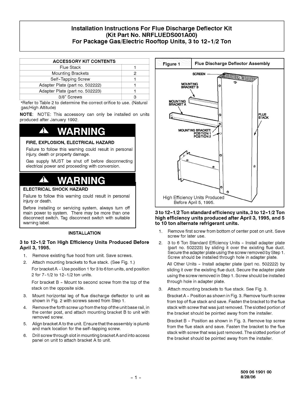
Figure 1Flue Discharge Deflector Assembly
SCREEN
MOUNTING
BRACKET B
MOUNTING
BRACKET A
MOUNTING BRACKET:
POSITION 1
POSITION 2
High Efficiency Units Produced
Before April 5, 1995.
FLUE
STACK
/
3 to 12-1/2 Ton standard efficiency units, 3 to 12-1/2 Ton
high efficiency units produced after April 3, 1995, and 5
to 10 ton alternate refrigerant units.
1. Remove first screw from bottom of center post on unit. Save
screw for later use.
2. 3 to 6 Ton Standard Efficiency Units - Install adapter plate
(part no. 502223) by sliding it over the existing flue duct.
Secure the adapter plate using the screw removed by Step 1.
Screw should be installed through hole in adapter plate.
All Other Units - Install adapter plate (part no. 502222) by
sliding it over the existing flue duct. Secure the adapter plate
using the screw removed in Step 1. Screw should be installed
through hole in adapter plate.
3. Attach mounting brackets to flue stack. See Fig. 3.
Bracket A - Position as shown in Fig. 3. Remove fourth screw
from top of flue stack and save. Fasten the bracket to the flue
stack with screw that was just removed. The slotted portion of
the bracket should be pointed away from the installer.
Bracket B - Position as shown in Fig. 3. Remove top screw
from the flue stack and save. Fasten the bracket to the flue
stack with screw that was just removed. The slotted portion of
the bracket should be pointed away from the installer.
509 06 1901 00
- 1 - 8/28/06
4. Remove the two screws in the center post that are attached to SERVICE
the top cover. Remove the second screw from the bottom on
the center post. Save all screws. See Fig. 4.
5. Mount the flue discharge deflector to unit by fastening the
horizontal leg of the flue stack to the adapter plate using the
three 3/8-in. screws supplied. Line up the slots in brackets A
and B with the holes from the screws removed in Step 4.
Reinstall screws from Step 4.
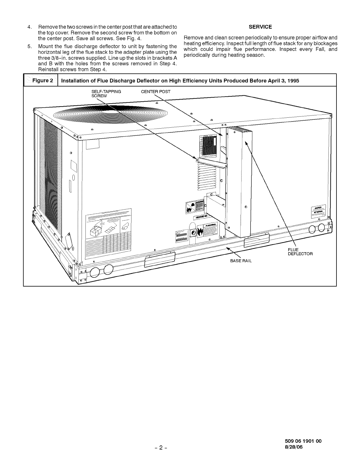
Figure2/",°s,o.otiono,FlueOiso.orgeOe.eotoron.1_.E.ioienoyU°.sProducedBe,oreAp.,3,,995
i
Remove and clean screen periodically to ensure proper airflow and
heating efficiency. Inspect full length of flue stack for any blockages
which could impair flue performance. Inspect every Fall, and
periodically during heating season.
SELF-TAPPING CENTER POST
SC RE-VV
BASE RAIL
FLUE
DEFLECTOR
509 06 1901 O0
- 2 - 8/28/06
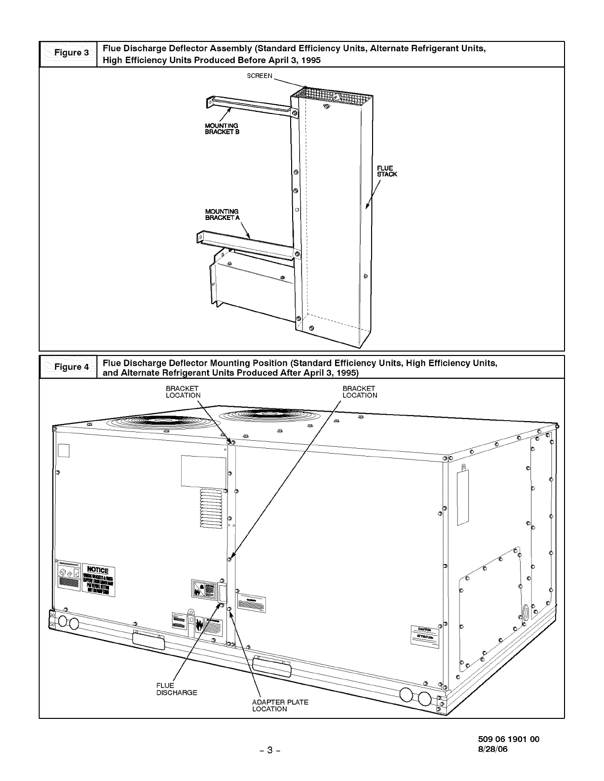
Figuie 3IHighFlUeDischargeDeflectorEfficiencyUnits ProducedAssemblYBefore(StandardApril3, Efficiency U nits, AlternateRefrigerant1995 Units,
SCREEN
MOUNTING
BRACKET B
MOUNTING
BRACKETA
FLUE
STACK
/
i=,gHr_ 4 I Flue Discharge Deflector Mounting Position (Standard Efficiency Units, High Efficiency Units,
and Alternate Refri_ierant Units Produced After April 3, 1995)
BRACKET BRACKET
LOCATION LOCATION
FLUE
DISCHARGE \
ADAPTER PLATE
LOCATION
509 06 1901 00
-3- 8/28/06
