ICP Furnace/Heater, Gas Manual L0910214
User Manual: ICP ICP Furnace/Heater, Gas Manual ICP Furnace/Heater, Gas Owner's Manual, ICP Furnace/Heater, Gas installation guides
Open the PDF directly: View PDF ![]() .
.
Page Count: 58
95+ SINGLE STAGE GAS FURNACE DIRECT
OR NON-DIRECT VENT
Category IV Furnace
*9M PX Upflow/Horizontal/Downflow
* Denotes Brands (C, H, T)
SAFETY CONSIDERATIONS
Improper installation, adjustment, alteration, service, maintenance, or use can cause explosion, fire, electrical shock, or other
conditions which may cause death, personal injury, or property damage. Consult a qualified installer, service agency, or your
distributor or branch for information or assistance. The qualified installer or agency must use factory-authorized kits or accessories
when modifying this product. Refer to the individual instructions packaged with the kits or accessories when installing.
Follow all safety codes. Wear safety glasses, protective clothing, and work gloves. Use quenching cloth for brazing operations.
Have fire extinguisher available. Read these instructions thoroughly and follow all warnings or cautions included in literature and
attached to the unit. Consult local building codes, the current editions of the National Fuel Gas Code (NFCG) NFPA 54/ANSI
Z223.1, and the National Electrical Code (NEC) NFPA 70.
In Canada refer to the current editions of the National standards of Canada CAN/CSA-B149.1 and .2 Natural Gas and Propane
Installation Codes, and Canadian Electrical Code CSA O22.1.
Recognize safety information. This is the safety-alert symbol /iX. When you see this symbol on the unit and in instructions or
manuals, be alert to the potential for personal injury. Understand these signal words; DANGER, WARNING, and CAUTION. These
words are used with the safety-alert symbol. DANGER identifies the most serious hazards which will result in severe personal
injury or death. WARNING signifies hazards which could result in personal injury or death. CAUTION is used to identify unsafe
practices which may result in minor personal injury or product and property damage. NOTE is used to highlight suggestions which
will result in enhanced installation, reliability, or operation.
®
International Comfort Products, LLC Table of Contents
Lewisburg, TN 37091 U.S.A.
1. Safe Installation Requirements .................... 4
2. Installation ................................... 5
3. Combustion & Ventilation Air ..................... 9
4. Vent & Combustion Air Piping .................... 13
5. Concentric Vent Termination ..................... 32
6. Gas Supply and Piping ......................... 34
INSTALLER: Affix these instructions
on or adjacent to the furnace.
CONSUMER: Retain these
instructions for future reference.
7. ElectricalWiring ............................. 39
8. Ductworkand Filter ........................... 40
9. ChecksandAdjustments....................... 44
10. FurnaceMaintenance......................... 46
11.Sequenceof Operation& Diagnostics ............ 47
TechnicalSupport .............................. 49
CARBON MONOXIDE POISONING AND FIRE
ELECTRIC SHOCK HAZARD HAZARD
Failure to follow this warning Failure to follow this warning could result in
could result in personal injury personal injury, death, and/or property dam-
and/or death, age.
Turn Off All Power Before This furnace is not designed for use in mobile
Servicing. homes, trailers or recreational vehicles.
Portions of the text and tables are reprinted from NFPA 54 /ANSi Z223,1-2006@, with permission of National Fire Protection Association, Quincy, MA 02269 and American Gas Association,
Washington, DC 20001. This reprinted material is not the complete and official position of the NFPA or ANSi, on the referenced subject, which is represented only by the standard in its
fintirfit¥,
Printed in U.S.A. 440 01 1051 01 July 2009
Specifications are subject to change without notice.
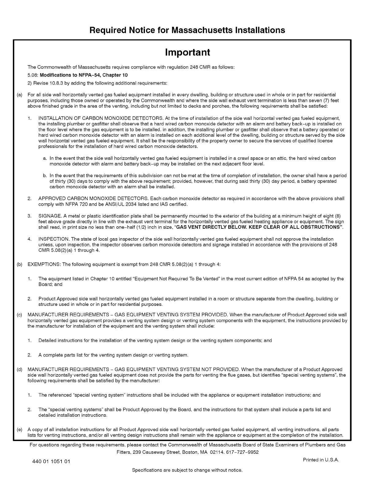
Required Notice for Massachusetts Installations
(a)
Important
The Commonwealth of Massachusetts requires compliance with regulation 248 CMR as follows:
5.08: Modifications to NFPA-54, Chapter 10
2) Revise 10.8.3 by adding the following additional requirements:
For all side wall horizontally vented gas fueled equipment installed in every dwelling, building or structure used in whole or in part for residential
purposes, including those owned or operated by the Commonwealth and where the side wall exhaust vent termination is less than seven (7) feet
above finished grade in the area of the venting, including but not limited to decks and porches, the following requirements shall be satisfied:
1, INSTALLATION OF CARBON MONOXIDE DETECTORS. At the time of installation of the side wall horizontal vented gas fueled equipment,
the installing plumber or gasfitter shall observe that a hard wired carbon monoxide detector with an alarm and battery back-up is installed on
the floor level where the gas equipment is to be installed, in addition, the installing plumber or gasfitter shall observe that a battery operated or
hard wired carbon monoxide detector with an alarm is installed on each additional level of the dwelling, building or structure served by the side
wall horizontal vented gas fueled equipment. It shall be the responsibility of the property owner to secure the services of qualified license
professionals for the installation of hard wired carbon monoxide detectors.
a. In the event that the side wall horizontally vented gas fueled equipment is installed in a crawl space or an attic, the hard wired carbon
monoxide detector with alarm and battery back-up may be installed on the next adjacent floor level.
b. In the event that the requirements of this subdivision can not be met at the time of completion of installation, the owner shall have a period
of thirty (30) days to comply with the above requirement; provided, however, that during said thirty (30) day period, a battery operated
carbon monoxide detector with an alarm shall be installed.
2. APPROVED CARBON MONOXIDE DETECTORS. Each carbon monoxide detector as required in accordance with the above provisions shall
comply with NFPA 720 and be ANSI/UL 2034 listed and IAS certified.
3. SIGNAGE. A metal or plastic identification plate shall be permanently mounted to the exterior of the building at a minimum height of eight (8)
feet above grade directly in line with the exhaust vent terminal for the horizontally vented gas fueled heating appliance or equipment. The sign
shall read, in print size no less than one-half (1/2) inch in size, "GAS VENT DIRECTLY BELOW. KEEP CLEAR OF ALL OBSTRUCTIONS".
4. INSPECTION. The state of local gas inspector of the side wall horizontally vented gas fueled equipment shall not approve the installation
unless, upon inspection, the inspector observes carbon monoxide detectors and signage installed in accordance with the provisions of 248
CMR 5.08(2)(a) 1 through 4.
(b) EXEMPTIONS: The following equipment is exempt from 248 CMR 5.08(2)(a) 1 through 4:
(c)
(d)
(e)
1. The equipment listed in Chapter 10 entitled "Equipment Not Required To Be Vented" in the most current edition of NFPA 54 as adopted by the
Board; and
2. Product Approved side wall horizontally vented gas fueled equipment installed in a room or structure separate from the dwelling, building or
structure used in whole or in part for residential purposes.
MANUFACTURER REQUIREMENTS - GAS EQUIPMENT VENTING SYSTEM PROVIDED. When the manufacturer of Product Approved side wall
horizontally vented gas equipment provides a venting system design or venting system components with the equipment, the instructions provided by
the manufacturer for installation of the equipment and the venting system shall include:
1. Detailed instructions for the installation of the venting system design or the venting system components; and
2. A complete parts list for the venting system design or venting system.
MANUFACTURER REQUIREMENTS - GAS EQUIPMENT VENTING SYSTEM NOT PROVIDED. When the manufacturer of a Product Approved
side wall horizontally vented gas fueled equipment does not provide the parts for venting the flue gases, but identifies "special venting systems", the
following requirements shall be satisfied by the manufacturer:
1. The referenced "special venting system" instructions shall be included with the appliance or equipment installation instructions; and
2. The "special venting systems" shall be Product Approved by the Board, and the instructions for that system shall include a parts list and
detailed installation instructions.
A copy of all installation instructions for all Product Approved side wall horizontally vented gas fueled equipment, all venting instructions, all parts
lists for venting instructions, and/or all venting design instructions shall remain with the appliance or equipment at the completion of the installation.
For questions regarding these requirements, please contact the Commonwealth of Massachusetts Board of State Examiners of Plumbers and Gas
Fitters, 239 Causeway Street, Boston, MA 02114. 617-727-9952
440 01 1051 01 Printed in U.S.A.
Specifications are subject to change without notice.
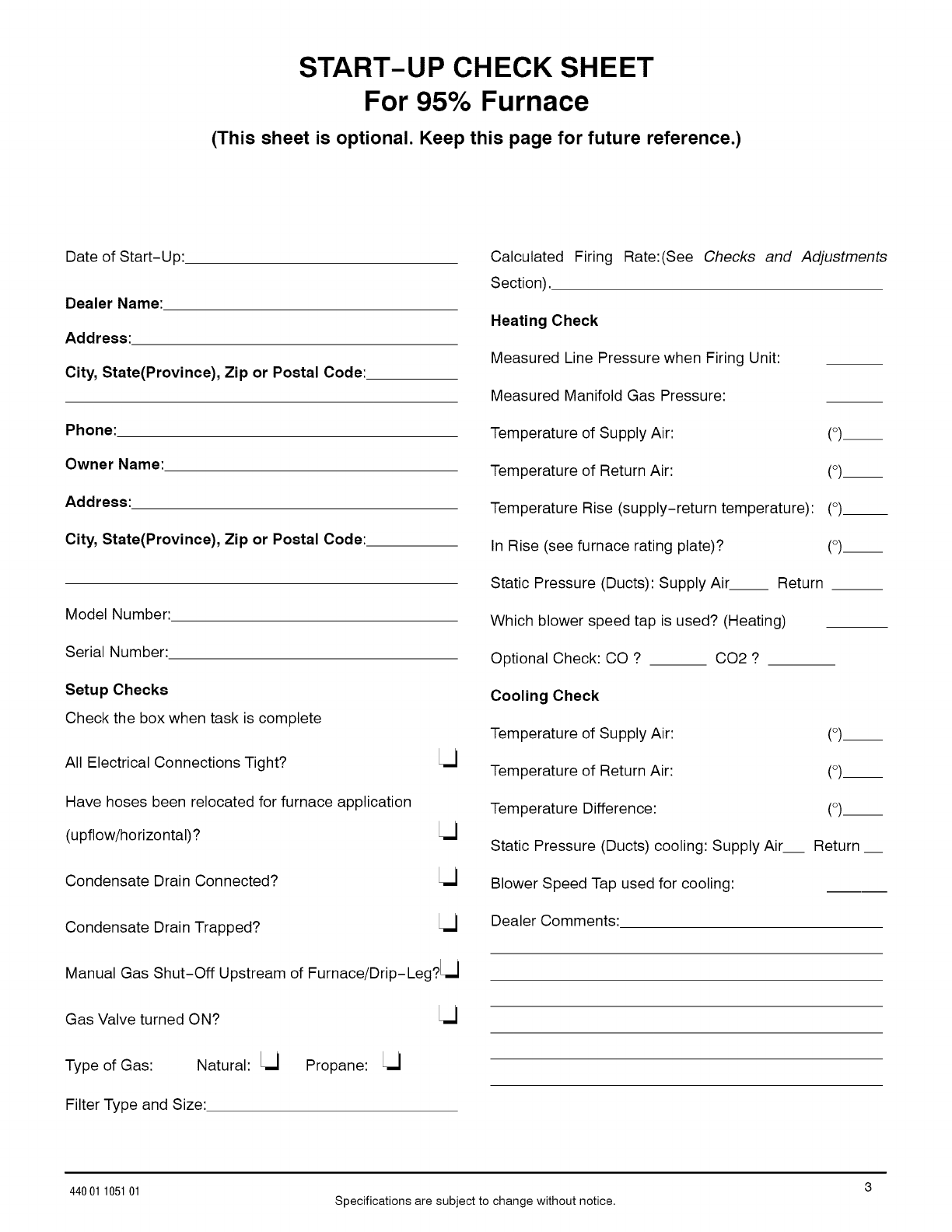
START-UP CHECK SHEET
For 95% Furnace
(This sheet is optional. Keep this page for future reference.)
Date of Start-Up:
Dealer Name:
Address:
City, State(Province), Zip or Postal Code:
Phone:
Owner Name:
Address:
City, State(Province), Zip or Postal Code:
Model Number:
Serial Number:
Setup Checks
Check the box when task is complete
All Electrical Connections Tight?
Have hoses been relocated for furnace application
(upflow/horizontal)?
Condensate Drain Connected?
Condensate Drain Trapped?
Manual Gas Shut-Off Upstream of Furnace/Drip-Leg?LU
Gas Valve turned ON?
Type of Gas: Natural: Lj
Filter Type and Size:
Propane: Lj
Calculated Firing Rate:(See Checks and
Section)..
Heating Check
Measured Line Pressure when Firing Unit:
Measured Manifold Gas Pressure:
Temperature of Supply Air: (o)__
Temperature of Return Air: (o)__
Temperature Rise (supply-return temperature): (o)__
In Rise (see furnace rating plate)? (o)__
Static Pressure (Ducts): Supply Air Return __
Which blower speed tap is used? (Heating)
Optional Check: CO ? CO2 ?
Cooling Check
Temperature of Supply Air: (o)__
Temperature of Return Air: (o)__
Temperature Difference: (o)__
Static Pressure (Ducts) cooling: Supply Air Return
Blower Speed Tap used for cooling:
Dealer Comments:
Adjustments
44001 105101 Specifications are subject to change without notice.
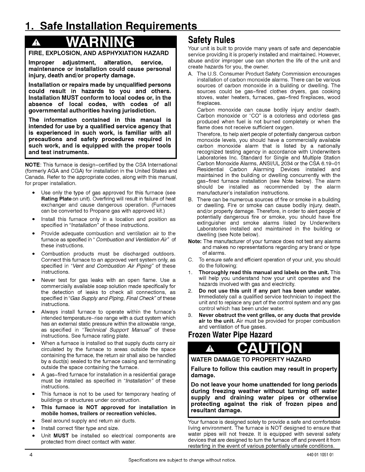
1. Safe Installation Requirements
FIRE, EXPLOSION, AND ASPHYXIATION HAZARD
Improper adjustment, alteration, service,
maintenance or installation could cause personal
injury, death and/or property damage.
Installation or repairs made by unqualified persons
could result in hazards to you and others.
Installation MUST conform to local codes or, in the
absence of local codes, with codes of all
governmental authorities having jurisdiction.
The information contained in this manual is
intended for use by a qualified service agency that
is experienced in such work, is familiar with all
precautions and safety procedures required in
such work, and is equipped with the proper tools
and test instruments.
NOTE: This furnace is design-certified by the CSA International
(formerly AGA and CGA) for installation in the United States and
Canada. Refer to the appropriate codes, along with this manual,
for proper installation.
• Use only the type of gas approved for this furnace (see
Rating Plate on unit). Overfiring will result in failure of heat
exchanger and cause dangerous operation. (Furnaces
can be converted to Propane gas with approved kit.)
• Install this furnace only in a location and position as
specified in "Installation" of these instructions.
• Provide adequate combustion and ventilation air to the
furnace as specified in "Combustion and Ventilation Air" of
these instructions.
Combustion products must be discharged outdoors.
Connect this furnace to an approved vent system only, as
specified in "Vent and Combustion Air Piping" of these
instructions.
Never test for gas leaks with an open flame. Use a
commercially available soap solution made specifically for
the detection of leaks to check all connections, as
specified in "Gas Supply and Piping, Final Check" of these
instructions.
• Always install furnace to operate within the furnace's
intended temperature-rise range with a duct system which
has an external static pressure within the allowable range,
as specified in "Technical Support Manual" of these
instructions. See furnace rating plate.
• When a furnace is installed so that supply ducts carry air
circulated by the furnace to areas outside the space
containing the furnace, the return air shall also be handled
by a duct(s) sealed to the furnace casing and terminating
outside the space containing the furnace.
• A gas-fired furnace for installation in a residential garage
must be installed as specified in "Installation" of these
instructions.
• This furnace is not to be used for temporary heating of
buildings or structures under construction.
• This furnace is NOT approved for installation in
mobile homes, trailers or recreation vehicles,
• Seal around supply and return air ducts.
• Install correct filter type and size.
• Unit MUST be installed so electrical components are
protected from direct contact with water.
SafetyRules
Your unit is built to provide many years of safe and dependable
service providing it is properly installed and maintained. However,
abuse and/or improper use can shorten the life of the unit and
create hazards for you, the owner.
A. The U.S. Consumer Product Safety Commission encourages
installation of carbon monoxide alarms. There can be various
sources of carbon monoxide in a building or dwelling. The
sources could be gas-fired clothes dryers, gas cooking
stoves, water heaters, furnaces, gas-fired fireplaces, wood
fireplaces.
Carbon monoxide can cause bodily injury and/or death.
Carbon monoxide or "CO" is a colorless and odorless gas
produced when fuel is not burned completely or when the
flame does not receive sufficient oxygen.
Therefore, to help alert people of potentially dangerous carbon
monoxide levels, you should have a commercially available
carbon monoxide alarm that is listed by a nationally
recognized testing agency in accordance with Underwriters
Laboratories Inc. Standard for Single and Multiple Station
Carbon Monoxide Alarms, ANSI/UL 2034 or the CSA 6.19-01
Residential Carbon Alarming Devices installed and
maintained in the building or dwelling concurrently with the
gas-fired furnace installation (see Note below). The alarm
should be installed as recommended by the alarm
manufacturer's installation instructions.
B. There can be numerous sources of fire or smoke in a building
or dwelling. Fire or smoke can cause bodily injury, death,
and/or property damage. Therefore, in order to alert people of
potentially dangerous fire or smoke, you should have fire
extinguisher and smoke alarms listed by Underwriters
Laboratories installed and maintained in the building or
dwelling (see Note below).
Note: The manufacturer of your furnace does not test any alarms
and makes no representations regarding any brand or type
of alarms.
C. To ensure safe and efficient operation of your unit, you should
do the following:
1. Thoroughly read this manual and labels on the unit, This
will help you understand how your unit operates and the
hazards involved with gas and electricity.
2. Do not use this unit if any part has been under water,
Immediately call a qualified service technician to inspect the
unit and to replace any part of the control system and any gas
control which has been under water.
3. Never obstruct the vent grilles, or any ducts that provide
air to the unit, Air must be provided for proper combustion
and ventilation of flue gases.
FrozenWaterPipeHazard
WATER DAMAGE TO PROPERTY HAZARD
Failure to follow this caution may result in property
damage.
Do not leave your home unattended for long periods
during freezing weather without turning off water
supply and draining water pipes or otherwise
protecting against the risk of frozen pipes and
resultant damage.
Your furnace is designed solely to provide a safe and comfortable
living environment. The furnace is NOT designed to ensure that
water pipes will not freeze. It is equipped with several safety
devices that are designed to turn the furnace off and prevent it from
restarting in the event of various potentially unsafe conditions.
4 440 01 105101
Specifications are subject to change without notice.
If your furnace remains off for an extended time, the pipes in your
home could freeze and burst, resulting in water damage.
If the structure will be unattended during cold weather you should
take these precautions.
1. Turn off the water supply to the structure and drain the water
lines if possible and add an antifreeze for potable water to
drain traps and toilet tanks. Open faucets in appropriate
areas.
-or-
2. Have someone check the structure frequently during cold
weather to make sure it is warm enough to prevent pipes
from freezing. Instruct them on a service agency to call to
provide service, if required.
-or-
3. Install a reliable remote sensing device that will notify
somebody of freezing conditions within the home.
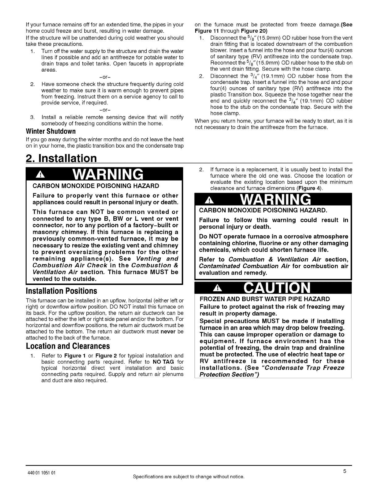
on the furnace must be protected from freeze damage.(See
Figure 11 through Figure 20)
1. Disconnect the 5/8"(15.9mm) OD rubber hose from the vent
drain fitting that is located downstream of the combustion
blower. Insert a funnel into the hose and pour four(4) ounces
of sanitary type (RV) antifreeze into the condensate trap.
Reconnect the 5/8" (15.9mm) OD rubber hose to the stub on
the vent drain fitting. Secure with the hose clamp.
2. Disconnect the 3/4" (19.1mm) OD rubber hose from the
condensate trap. Insert a funnel into the hose and and pour
four(4) ounces of sanitary type (RV) antifreeze into the
plastic Transition box. Squeeze the hose together near the
end and quickly reconnect the 3/4" (19.1mm) OD rubber
hose to the stub on the condensate trap. Secure with the
hose clamp.
When you return home, your furnace will be ready to start, as it is
Winter Shutdown
If you go away during the winter months and do not leave the heat
on in your home, the plastic transition box and the condensate trap
not necessary to drain the antifreeze from the furnace.
2. Installation
CARBON MONOXIDE POISONING HAZARD
Failure to properly vent this furnace or other
appliances could result in personal injury or death.
This furnace can NOT be common vented or
connected to any type B, BW or L vent or vent
connector, nor to any portion of a factory-built or
masonry chimney. If this furnace is replacing a
previously common-vented furnace, it may be
necessary to resize the existing vent and chimney
to prevent oversizing problems for the other
remaining appliance(s). See Venting and
Combustion Air Check in the Combustion &
Ventilation Air section. This furnace MUST be
vented to the outside.
2. If furnace is a replacement, it is usually best to install the
furnace where the old one was. Choose the location or
evaluate the existing location based upon the minimum
clearance and furnace dimensions (Figure 4).
CARBON MONOXIDE POISONING HAZARD.
Failure to follow this warning could result in
personal injury or death.
Do NOT operate furnace in a corrosive atmosphere
containing chlorine, fluorine or any other damaging
chemicals, which could shorten furnace life.
Refer to Combustion & Ventilation Air section,
Contaminated Combustion Air for combustion air
evaluation and remedy.
InstallationPositions
This furnace can be installed in an upflow, horizontal (either left or
right) or downflow airflow position. DO NOT install this furnace on
its back. For the upflow position, the return air ductwork can be
attached to either the left or right side panel and/or the bottom. For
horizontal and downflow positions, the return air ductwork must be
attached to the bottom. The return air ductwork must never be
attached to the back of the furnace.
Locationand Clearances
Refer to Figure 1 or Figure 2 for typical installation and
basic connecting parts required. Refer to NO TAG for
typical horizontal direct vent installation and basic
connecting parts required. Supply and return air plenums
and duct are also required.
FROZEN AND BURST WATER PIPE HAZARD
Failure to protect against the risk of freezing may
result in property damage.
Special precautions MUST be made if installing
furnace in an area which may drop below freezing.
This can cause improper operation or damage to
equipment. If furnace environment has the
potential of freezing, the drain trap and drainline
must be protected. The use of electric heat tape or
RV antifreeze is recommended for these
installations. (See "Condensate Trap Freeze
Protection Section")
44001 105101 Specifications are subject to change without notice.
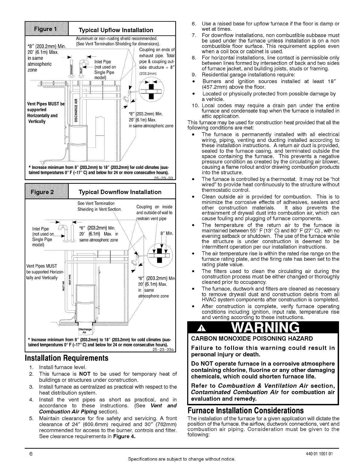
Typical Upflow Installation
Aluminumornon-rustingshieldrecommended,
"8" (2032mml Min (SeeVentTerminationShieldingfordimensions),
............ ' ":_ _ Couplingonendsof
20' (6.1m)Max.
in same >'; I_ '_/ exhaustpipe,Total
tl l_ InletPipe pipe& couplingout-
atmospheric ]i/_ (notusedon side structure= 8"
zone /_'1 SinglePipe (203.2mm)
VentPipes MUSTbei
supported
Horizontallyand Min,
Max,
*Increaseminimumfrom 8" (203.2mm)to 18" (203.2mm)for coldclimates(sus-
tainedtemperatures0° F (-17°C)and belowfor 24 or moreconsecutivehours),
2,5-2,1-,1,!
Typical Downflow Installation
SeeVentTermination
ShieldinginVentSection, Couplingon inside
\ andoutsideofwallto
'_ ,,restrainventpipe
_ \ i\ '
InletPipe "8" (203.2mm)Min, \,
(notusedon 20' (6.1m) Max, in \ 8"Min,
SinglePipe sameatmosphericzone
model)
VentPipesMUST
be supportedHorizon-
tallyand Vertically (203.2mm) Min
(6.1m) Max.
same
iosphericzone
/
i
i Air
*Increaseminimumfrom8" (203.2mm)to18" (203.2mm)for coldclimates(sus-
tainedtemperatures0° F(-17°C)andbelowfor24ormoreconsecutivehours),
25-23-33a
InstallationRequirements
1. Install furnace level.
2. This furnace is NOT to be used for temporary heat of
buildings or structures under construction.
3. Install furnace as centralized as practical with respect to the
heat distribution system.
4. Install the vent pipes as short as practical, and in
accordance to these instructions. (See Vent and
Combustion Air Piping section).
5. Maintain clearance for fire safety and servicing. A front
clearance of 24" (609.6mm) required and 30" (762mm)
recommended for access to the burner, controls and filter.
See clearance requirements in Figure 4.
6. Use a raised base for upflow furnace if the floor is damp or
wet at times.
7. For downflow installations, non combustible subbase must
be used under the furnace unless installation is on a non
combustible floor surface. This requirement applies even
when a coil box or cabinet is used.
8. For horizontal installations, line contact is permissible only
between lines formed by intersection of back and two sides
of furnace jacket, and building joists, studs or framing.
9. Residential garage installations require:
• Burners and ignition sources installed at least 18"
(457.2mm) above the floor.
• Located or physically protected from possible damage by
a vehicle.
10. Local codes may require a drain pan under the entire
furnace and condensate trap when the furnace is installed in
attic application.
This furnace may be used for construction heat provided that all the
following conditions are met:
• The furnace is permanently installed with all electrical
wiring, piping, venting and ducting installed according to
these installation instructions. A return air duct is provided,
sealed to the furnace casing, and terminated outside the
space containing the furnace. This prevents a negative
pressure condition as created by the circulating air blower,
causing a flame rollout and/or drawing combustion products
into the structure.
• The furnace is controlled by a thermostat. It may not be "hot
wired" to provide heat continuously to the structure without
thermostatic control.
• Clean outside air is provided for combustion. This is to
minimize the corrosive effects of adhesives, sealers and
other construction materials. It also prevents the
entrainment of drywall dust into combustion air, which can
cause fouling and plugging of furnace components.
• The temperature of the return air to the furnace is
maintained between 55° F (13° C) and 80° F (27° C), with no
evening setback or shutdown. The use of the furnace while
the structure is under construction is deemed to be
intermittent operation per our installation instructions.
• The air temperature rise is within the rated rise range on the
furnace rating plate, and the firing rate has been set to the
rating plate value.
• The filters used to clean the circulating air during the
construction process must be either changed or thoroughly
cleaned prior to occupancy.
• The furnace, ductwork and filters are cleaned as necessary
to remove drywall dust and construction debris from all
HVAC system components after construction is completed.
• After construction is complete, verify furnace operating
conditions including ignition, input rate, temperature rise
and venting according to these instructions.
CARBON MONOXIDE POISONING HAZARD
Failure to follow this warning could result in
personal injury or death.
Do NOT operate furnace in a corrosive atmosphere
containing chlorine, fluorine or any other damaging
chemicals, which could shorten furnace life.
Refer to Combustion & Ventilation Air section,
Contaminated Combustion Air for combustion air
evaluation and remedy.
FurnaceInstallationConsiderations
The installation of the furnace for a given application will dictate the
position of the furnace, the airflow, ductwork connections, vent and
combustion air piping. Consideration must be given to the
following:
Specifications are subject to change without notice.
440 01 105101
Condensate Trap and Drain Lines
The supplied condensate trap must be attached to the furnace side
panel on either the left or right side. For horizontal installations, the
drain trap isvertically attached to the side panel below the furnace.
A minimum clearance of 6" (152.4mm) below the furnace is
required for the condensate trap. Downward slope of the
condensate drain line from the condensate trap to the drain
location must be provided. Adequate freeze protection of the drain
trap and the drain line must be provided. See "Condensate Drain
Trap" section for further details.
Leveling
Proper leveling of the furnace must be provided to insure proper
drainage of the condensate from the furnace. The furnace must be
level to within 1/4" (6.4mm) from front to back and from side to side
for upflow and downflow installations or top to bottom for horizontal
installations.
Vent and CombustionAir Connections
For venting information literature, call 931.270.4100 with the
complete model and serial number of the furnace.
Special Venting Requirements for Installations in Canada
Installation in Canada must conform to the requirements of CSA
B149 code. Vent systems must be composed of pipe, fittings,
cements, and primers listed to ULC S636. The special vent
fittings and accessory concentric vent termination kits and
accessory external drain trap have been certified to ULC S636
for use with those IPEX PVC vent components which have
been certified to this standard. In Canada, the primer and
cement must be of the same manufacturer as the vent system -
IPEX System 636, PVC/CPVC Primer, Purple Violet for Flue
Gas Venting and IPEX System 636_1/ ,M, PVC Cement for Flue
Gas Venting, rated Class IIA, 65 deg'C, must be used with this
venting system - do not mix primers and cements from one
manufacturer with a vent system from a different manufacturer.
Follow the manufacturer's instructions in the use of primer and
cement and never use primer or cement beyond its expiration
date.
The safe operation, as defined by ULC S636, of the vent
system is based on following these installation instructions, the
vent system manufacturer's installation instructions, and proper
use of primer and cement. All fire stop and roof flashing used
with this system must be UL listed material. Acceptability under
Canadian standard CSA B149 is dependent upon full
compliance with all installation instructions. Under this
standard, it is recommended that the vent system be checked
once a year by qualified service personnel.
The authority having jurisdiction (gas inspection authority,
municipal building department, fire department, etc) should be
consulted before installation to determine the need to obtain a
permit.
Consignes sp6ciales pour I'installation de ventillation au
Canada
L'installation faite au Canada dolt se conformer aux exigences
du code CSA B149. Ce syst_me de ventillation dolt se
composer de tuyaux, raccords, ciments et appr_ts conformes
au ULC S636. La tuyauterie de ventillation des gaz, ses
accessoires, le terminal concentrique mural ainsi que
I'ensemble du drain de condensat exterieur ont et6 certifies
ULCS 636 pour I'application des composantes IPEX PVC qui
sont certifiees & ce standard. Au Canada I'appr_t et le ciment
doivent _tre du m_me manufacturier que le syst_me de
ventillation - IPEX Systeme 636, Appr_t PVC/CPVC. Mauve
Violette pour conduit en evacuation des gaz et IPEX Systeme
636Cl/,M, ciment pour PVC pour conduit en evacuation des gaz,
6val'u_ CLASSE IIA, 65 deg. C. dolt etre utilise avec ce
systeeme d'evacuation - ne pas melanger I'appr_t et le ciment
d'un manufacturier avec le syst_me de ventillation d'un autre
manufacturier. Bien suivre les indications du manufacturier Iors
de I'utilisation de I'appr_t et du ciment et ne pas utiliser ceux-ci
si la date d'expiration est atteinte.
Uoperation securitaire, tel que definit par ULC S636, du
systeme de ventilation est base sur les instructions d'installation
suivantes, ainsi que I'usage approprie de I'appr_t et ciment.
Tout arret feu et solin de toit utitises avec ce systeme doivent
_tre des materiaux listes UL. Uacceptation du standard
Canadien CSA B419 est directement relie & I'installation
conforme aux instructions ci- haut mentionnees. Le standard
Canadien recommande I' inspection par un personel quatifie et
ce, une fois par annee.
Les autoritees ayant juridiction (inspecteurs de gas, inspecteurs
en b&timents, departement des incendies, etc) devraient _tre
consultees avant I'instatlation afin de determiner si un permis
est requis.
(1) System 636 is a trademark of IPEX Inc.
On the Dual Certified furnace, the vent and combustion air pipes
attach to the furnace through the top panel for the upflow and
horizontal installations. For the downflow installation, the vent and
combustion air pipes attach to the furnace through the alternate
locations on the furnace side panels.
Note: On the Direct Vent furnace, the vent pipe attaches to the
furnace through the side panels. The combustion air pipe attaches
to the top panel or to the alternate location on the side panel.
On the Single Pipe furnace, the vent pipe attaches to the furnace
through the furnace side panels.
Note: Repositioning of the combustion blower is required for the
vent pipe connection to the furnace through the "right side" panel.
See "Vent and Combustion Air Piping" section for further details.
HorizontalFurnaceInstallation
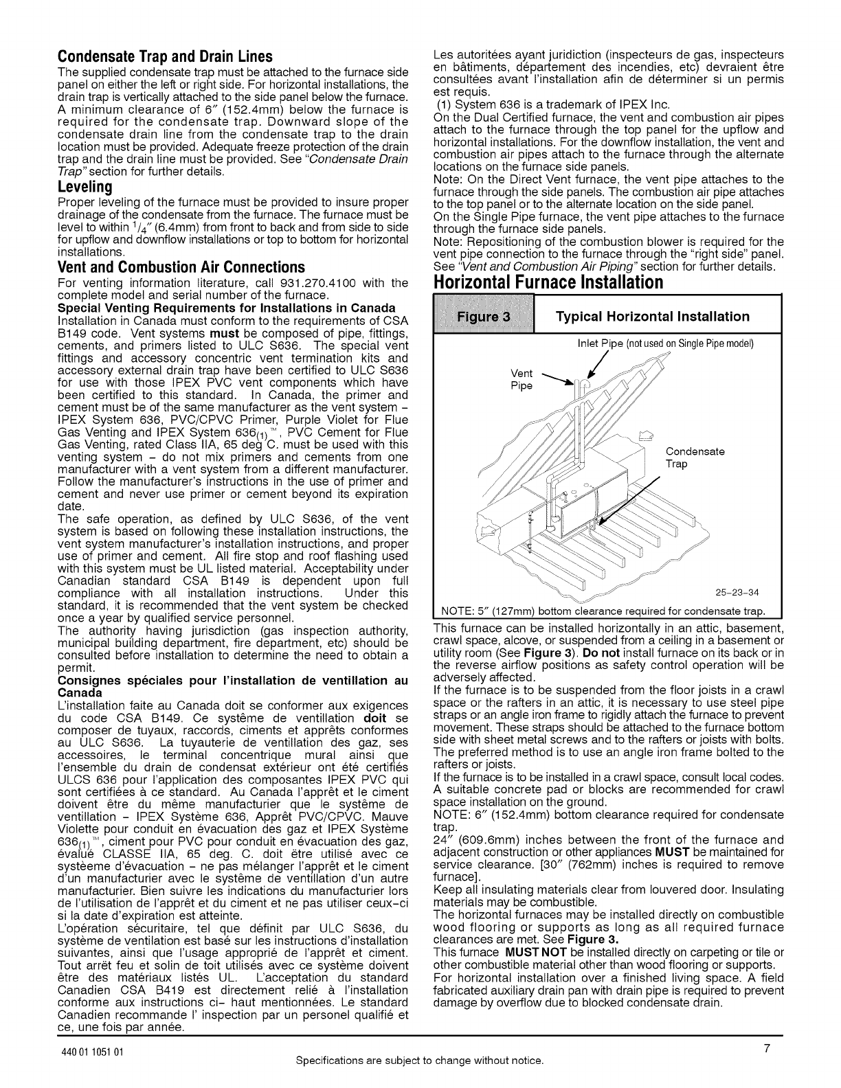
Typical Horizontal Installation
Inlet Pipe (notusedonSinglePipemodel)
Vent
Pipe
/'\ \
Condensate
Trap
25-23-34
NOTE: 5" (127mm) bottom clearance required for condensate trap.
This furnace can be installed horizontally in an attic, basement,
crawl space, alcove, or suspended from a ceiling in a basement or
utility room (See Figure 3). Do not install furnace on its back or in
the reverse airflow positions as safety control operation will be
adversely affected.
If the furnace is to be suspended from the floor joists in a crawl
space or the rafters in an attic, it is necessary to use steel pipe
straps or an angle iron frame to rigidly attach the furnace to prevent
movement. These straps should be attached to the furnace bottom
side with sheet metal screws and to the rafters or joists with bolts.
The preferred method is to use an angle iron frame bolted to the
rafters or joists.
If the furnace is to be installed in a crawl space, consult local codes.
A suitable concrete pad or blocks are recommended for crawl
space installation on the ground.
NOTE: 6" (152.4mm) bottom clearance required for condensate
trap.
24" (609.6mm) inches between the front of the furnace and
adjacent construction or other appliances MUST be maintained for
service clearance. [30" (762mm) inches is required to remove
furnace].
Keep all insulating materials clear from Iouvered door. Insulating
materials may be combustible.
The horizontal furnaces may be installed directly on combustible
wood flooring or supports as long as all required furnace
clearances are met. See Figure 3.
This furnace MUST NOT be installed directly on carpeting or tile or
other combustible material other than wood flooring or supports.
For horizontal installation over a finished living space. A field
fabricated auxiliary drain pan with drain pipe is required to prevent
damage by overflow due to blocked condensate drain.
44001 105101 Specifications are subject to change without notice.
[i[i[i;_i[i[i[iii!iiiiii[[ii_i_Xi:iiii[i!i!_iiiii_ii;¸;;;i[i[i_!ii_;_:iii[ii!iiiIii[i[iii;;i;;i;;ii_iii;iii[[I[[[[i_ii1[[ii_i_1iIi_i:
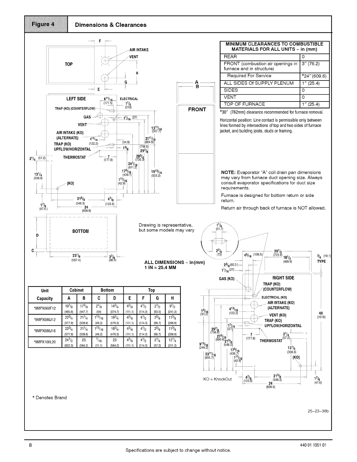
_!_i_:! I Dimensions & Clearances
iiiiiiiiiiiiiiiiiiiiiiiiiiiiiiiiiiiiiiiiiiiiiiiiiiiiiiiiiiiiiiiiiiiiiiiiiiiiiiiiiiiiiiiiiiiiiiiiiiiiiiiiiiiiiiiiiiiiiiiiiiiiiiiiiiiiiiiiiiiiiiiiiiii
oq F_o
LEFTSIDE _611116, iELECTRICAL
i ii775)--i 11
TRAP (KO (COUNTERFLOW)- - _,_, i (318)
i OAS
VENT ........... _ /_ '
- 11311116
AIR INTAKE (KO) _j (347.7)
(ALTERNATE) ..... _13_1_ " --/ ii3111/./
TRAP (KO) 122.2 _-¢ ) (34.9) ;; ;;(804:9_
_'i572i UPFLOW/HOR ZONTAL "//:_ i_ _!3/6i 24i/161i70--i(72_87"8I'8 '
THERMOSTAT "_ ........ 7i28314
21/ 4 : _ (177.8) J3 .3)i i
i 5i (61 .2) i :: i
21518 47/ i
47, (549.3) (123.8) i
'/8 ;-.... 24
(47.6) ......................................................................................i
(609.6)
i, _
il
; i
:1 BOTTOM
I
D_
Drawing is representative,
but some models may vary
MINIMUM CLEARANCES TO COMBUSTIBLE
MATERIALS FOR ALL UNITS -in (mm)
REAR 0
FRONT (combustion air openings in 3" (76.2)
furnace and in structure)
Required For Service *24" (609.6)
ALL SIDES Of SUPPLY PLENUM 1" (25.4)
SIDES 0
VENT 0
.................................................:TOP OF FURNACE 1" (25.4)
FRONT ii *30" (762mm)clearancerecommendedforfurnaceremoval,
_ Horizontalposition:Linecontactis permissibleonly between
_ linesformed by intersectionsof top and two sidesof furnace
_ 'acket,and buildingjoists, studsor framing,
NOTE: Evaporator "A" coil drain pan dimensions
may vary from furnace duct opening size. Always
consult evaporator specifications for duct size
requirements.
Furnace is designed for bottom return or side
return.
Return air through back of furnace is NOT allowed.
C_; Lo 23118 o! '
(587.4) 37(_) ....
Unit Cabinet Bottom
Capacity
*9MPX060F12
*9MPX080J12
*9MPX080J16
*9MPXl00L20
ABCD E F G H
191/8 175/8 21/8 143/4 43/8 41/2 21/2 91/2
(485.8) (447.7) (54) (374.7) (111.1) (114.3) (63.5) (241.3)
223/4 211/4 115/16 183/4 43/8 41/2 25/8 113/8
(577.9) (539.8) (49.2) (476.3) (111.1) (114.3) (66.7) (288.9)
223/4 211/4 115/16 183/4 43/8 41/2 25/8 113/8
(577.9) (539.8) (49.2) (476.3) (111.1) (114.3) (66.7) (288.9)
241/2 23 7/16 23 43/8 41/2 21/4 121/4
(622.3) (584.2) (11.1} (584.2) (111.1} (114.3) (57.21 (311.21
i i ', ........... 7
Jj
27/8 i/' 281/2 o-_
73) / j45/t_ (109.5), (723.9) .^t J(19.1
"- ........ i "- _ /u'/2 _-_ 3/4
ALL DIMENSIONS - in(mm) '- _=_ .' (469.9) i TYPE
23/8 60.3 }_J T_ ./
1 IN =25.4 MM 11116(27)-_ C_ I
AS(KO) :7 R,GHTS,DE
_,_:: .," TRAP (KO) i
Top L_ //(COUNTERFLOW) i
............................i _ --_- ELECTRICAL(KO) i
/I/:_ /AIR INTAKE (KO) i
i413/6 i ,\ys. (ALTERNATE) i
1_2_i i 1122,2)- i_i_ ......... VENT (KOI i 114%)
1 .......................................... TRAP (KO) i
ilii6 iiii_ i:/ : UPFLOW/HORIZONTAL J
297/R (27)i ?'_
(758.8) 'i J.... 7_21/4 _ =
=ii
- (273/61_15/8 j(177.8)THE\R MOSTAT(57.2) l.............................., j
91:J/16 (549 3 i .11 ,i ;
249.2) 4,5, [ 1,.1/4 [
= r /16 i (336 6)
3311/,:- (439.7 i ' i
855._1_' 111/_61 (KO) ;
42.9)
........[ 47` I.........................21 /8 .......................................... 7_
KO = KnockOut [,_o_, 549.3 1 /8
_ :'-":_'J 24 (47.6)
(609.6)
* Denotes Brand
25-23-36b
Specifications are subject to change without notice.
440 01 105101
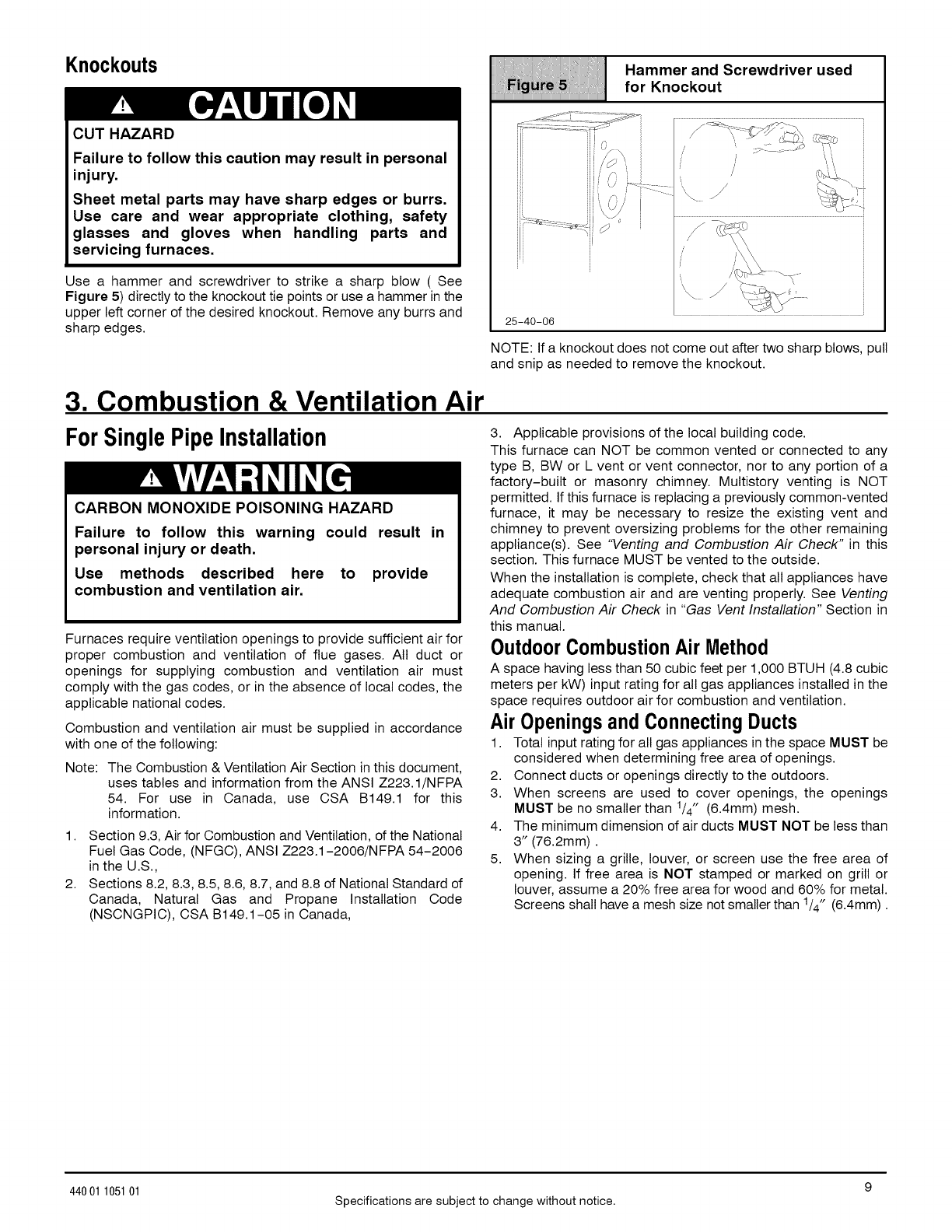
Knockouts Hammer and Screwdriver used
.........................................................................................................................................................for Knockout
CUTHAZARD
Failure to follow this caution may result in personal
injury.
Sheet metal parts may have sharp edges or burrs.
Use care and wear appropriate clothing, safety
glasses and gloves when handling parts and
servicing furnaces.
Use a hammer and screwdriver to strike a sharp blow ( See
Figure 5) directly to the knockout tie points or use a hammer in the
upper left corner of the desired knockout. Remove any burrs and
sharp edges. 25-40-06
NOTE: If a knockout does not come out after two sharp blows, pull
and snip as needed to remove the knockout.
3. Combustion & Ventilation Air
For SinglePipeInstallation
CARBON MONOXIDE POISONING HAZARD
Failure to follow this warning could result in
personal injury or death.
Use methods described here to provide
combustion and ventilation air.
Furnaces require ventilation openings to provide sufficient air for
proper combustion and ventilation of flue gases. All duct or
openings for supplying combustion and ventilation air must
comply with the gas codes, or in the absence of local codes, the
applicable national codes.
Combustion and ventilation air must be supplied in accordance
with one of the following:
Note: The Combustion & Ventilation Air Section in this document,
uses tables and information from the ANSI Z223.1/NFPA
54. For use in Canada, use CSA B149.1 for this
information.
1. Section 9.3, Air for Combustion and Ventilation, of the National
Fuel Gas Code, (NFGC), ANSI Z223.1-2006/NFPA 54-2006
in the U.S.,
2. Sections 8.2, 8.3, 8.5, 8.6, 8.7, and 8.8 of National Standard of
Canada, Natural Gas and Propane Installation Code
(NSCNGPIC), CSA B149.1-05 in Canada,
3. Applicable provisions of the local building code.
This furnace can NOT be common vented or connected to any
type B, BW or L vent or vent connector, nor to any portion of a
factory-built or masonry chimney. Multistory venting is NOT
permitted. If this furnace is replacing a previously common-vented
furnace, it may be necessary to resize the existing vent and
chimney to prevent oversizing problems for the other remaining
appliance(s). See "Venting and Combustion Air Check" in this
section. This furnace MUST be vented to the outside.
When the installation is complete, check that all appliances have
adequate combustion air and are venting properly. See Venting
And Combustion Air Check in "Gas Vent Installation" Section in
this manual.
OutdoorCombustionAir Method
A space having less than 50 cubic feet per 1,000 BTUH (4.8 cubic
meters per kW) input rating for all gas appliances installed in the
space requires outdoor air for combustion and ventilation.
Air Openingsand ConnectingDucts
1. Total input rating for all gas appliances in the space MUST be
considered when determining free area of openings.
2. Connect ducts or openings directly to the outdoors.
3. When screens are used to cover openings, the openings
MUST be no smaller than 1/4" (6.4mm) mesh.
4. The minimum dimension of air ducts MUST NOT be less than
3" (76.2mm).
5. When sizing a grille, louver, or screen use the free area of
opening. If free area is NOT stamped or marked on grill or
louver, assume a 20% free area for wood and 60% for metal.
Screens shall have a mesh size not smaller than 1/4" (6.4mm).
44001 105101 Specifications are subject to change without notice.
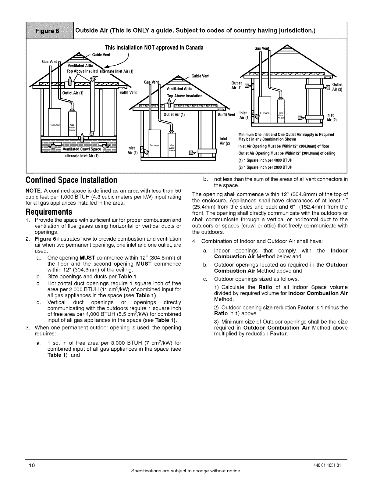
Outside Air (This is ONLY a guide. Subject to codes of country having jurisdiction.)
GasVent
This installation NOT approved in Canada GasVent
Above Insulati,alternate InletAir (1) _ _1 _ I_- _- _- _- _- _- _- _- _- _- _- =_
._.,i GableVent _;::1 °_"
_, _ GasVent _Outlet _J II II JILL[-- ou
_ n _S'ventilated Attic_ Air I,I I II Airtlet
OutletAir (1) SoffitVent IGfll _I II 31 II II (2)
,,iFI1 p bovelnsulation II II
I II I10utletAir(1) SoffitVent In,le!j, _,F ..... H_;-I ___--_ Inlet
I LL_ .,r,,, ]-._ i p,orl _ln,_l_ Air (2)
I I I _ Minimum OneInlet and OneOutletAir Supply is Required
I I I I I Inlet May be in any CombinationShown
Air (2)
Inlet _ ...... IU _Inlet Air Opening Must be Within12"(304.8mm)°f fl°°r
alternate lnletAir (1) Air(l) _'_ I I_1 _1_ OutletAir OpeningMustbe Withinl2,, (304.8mm)of ceiling
(1) 1SquareInch per4000 BTUH
(2) 1SquareInch per2000 BTUH
ConfinedSpaceInstallation
NOTE: A confined space is defined as an area with less than 50
cubic feet per 1,000 BTUH (4.8 cubic meters per kW) input rating
for all gas appliances installed in the area.
Requirements
1. Provide the space with sufficient air for proper combustion and
ventilation of flue gases using horizontal or vertical ducts or
openings.
2. Figure 6 illustrates how to provide combustion and ventilation
air when two permanent openings, one inlet and one outlet, are
used.
a. One opening MUST commence within 12" (304.8mm) of
the floor and the second opening MUST commence
within 12" (304.8mm) of the ceiling.
b. Size openings and ducts per Table 1.
c. Horizontal duct openings require 1 square inch of free
area per 2,000 BTUH (11 cm2/kW) of combined input for
all gas appliances in the space (see Table 1).
d. Vertical duct openings or openings directly
communicating with the outdoors require 1 square inch
of free area per 4,000 BTUH (5.5 cm2/kW) for combined
input of all gas appliances in the space (see Table 1).
3. When one permanent outdoor opening is used, the opening
requires:
a. 1 sq. in of free area per 3,000 BTUH (7 cm2/kW) for
combined input of all gas appliances in the space (see
Table 1) and
b. not less than the sum of the areas of all vent connectors in
the space.
The opening shall commence within 12" (304.8mm) of the top of
the enclosure. Appliances shall have clearances of at least 1"
(25.4mm) from the sides and back and 6" (152.4mm) from the
front. The opening shall directly communicate with the outdoors or
shall communicate through a vertical or horizontal duct to the
outdoors or spaces (crawl or attic) that freely communicate with
the outdoors.
4. Combination of Indoor and Outdoor Air shall have:
a,
b.
C.
Indoor openings that comply with the Indoor
Combustion Air Method below and
Outdoor openings located as required in the Outdoor
Combustion Air Method above and
Outdoor openings sized as follows.
1) Calculate the Ratio of all Indoor Space volume
divided by required volume for Indoor Combustion Air
Method.
2) Outdoor opening size reduction Factor is I minus the
Ratio in 1) above.
3) Minimum size of Outdoor openings shall be the size
required in Outdoor Combustion Air Method above
multiplied by reduction Factor.
10
Specifications are subject to change without notice.
440 01 105101
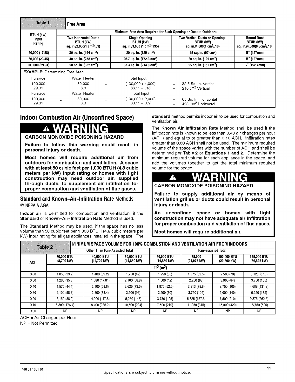
ilii!i! IiFreeArea
MinimumFreeArea Requiredfor EachOpeningorDuctto Outdoors
STUB(kW)
Input TwoHorizontalDucts SingleOpening TwoVerticalDuctsorOpenings RoundDuct
Rating BTUH(kW) BTUH(kW) BTUH(kW) BTUH(kW)
sq. in./2,000(1cm2/.09) sq. in./3,000(1cm2/.135) sq.in./4,000(1cm2/.18) sq. in./4,000(6.5cm2/.18)
60,000(17.58) 30 sq. in.(194 cm2) 20sq. in. (129cm2) 15 sq. in.(97cm2) 5" (127mm)
80,000(23.45) 40 sq.in. (258cm2) 26.7 sq.in. (172.3cm2) 20 sq.in. (129cm2) 5" (127mm)
100,000(29.31) 50 sq.in. (322cm2) 33.3 sq.in. (214.8cm2) 25 sq.in. (161cm2) 6" (152.4mm)
EXAMPLE: Determining Free Area
Furnace Water Heater Total Input
100,000 + 30,000 = (130,000 + 4,000) 32.5 Sq. In. Vertical
29.31 8.8 (38.11 + . 18) 210 cm2 Vertical
Furnace Water Heater Total Input
100,000 + 30,000 = (130,000 + 2,000) 65 Sq. In. Horizontal
29.31 8.8 (38.11 + .09) 423 cm2 Horizontal
IndoorCombustionAir (UnconfinedSpace) standard method permits indoor air to be used for combustion and
ventilation air.
CARBON MONOXIDE POISONING HAZARD
Failure to follow this warning could result in
personal injury or death.
Most homes will require additional air from
outdoors for combustion and ventilation. A space
with at least 50 cubic feet per 1,000 BTUH (4.8 cubic
meters per kW) input rating or homes with tight
construction may need outdoor air, supplied
through ducts, to supplement air infiltration for
proper combustion and ventilation of flue gases.
Standard and Known-Air-Infiltration Rate Methods
© NFPA&AGA
Indoor air is permitted for combustion and ventilation, if the
Standard or Known-Air-Infiltration Rate Method is used.
The Known Air Infiltration Rate Method shall be used if the
infiltration rate is known to be less than 0.40 air changes per hour
(ACH) and equal to or greater than 0.10 ACH. Infiltration rates
greater than 0.60 ACH shall not be used. The minimum required
volume of the space varies with the number of ACH and shall be
determined per Table 2 or Equations 1 and 2. Determine the
minimum required volume for each appliance in the space, and
add the volumes together to get the total minimum required
volume for the space.
CARBON MONOXIDE POISONING HAZARD
Failure to supply additional air by means of
ventilation grilles or ducts could result in personal
injury or death.
The Standard Method may be used, if the space has no less
volume than 50 cubic feet per 1,000 BTUH (4.8 cubic meters per
kW) input rating for all gas appliances installed in the space. The
i, ,, ,-,,,,,_- MINIMUMSPACEVOLUMEFOR100%COMBUSTIONANDVENTILATIONAIR FROMINDOORS
OtherThan Fan-AssistedTotal Fan-assistedTotal
30,000BTU 40,000BTU 50,000 BTU 50,000 BTU 75,000 100,000BTU 125,000BTU
ACB (8,790kW) (11,720kW) (14,650kW) (14,650kW) (21,975kW) (29,300kW) (36,625kW)
ft3 (m3)
0.60 1,050(29.7) 1,400(39.2) 1,750(49) 1,250(35) 1,875(52.5) 2,500 (70) 3,125(87.5)
0.50 1,260(35.3) 1,680(47.04) 2,100 (58.8) 1,500(42) 2,250 (63) 3,000 (84) 3,750(105)
0.40 1,575(44.1) 2,100 (58.8) 2,625 (73.5) 1,875(52.5) 2,813 (78.8) 3,750 (105) 4,688(131.3)
0.30 2,100 (58.8) 2,800 (78.4) 3,500 (98) 2,500 (70) 3,750 (105) 5,000 (140) 6,250(175)
0.20 3,150 (88.2) 4,200(117.6) 5,250 (147) 3,750 (105) 5,625(157.5) 7,500 (210) 9,375(262.5)
0.10 6,300 (176.4) 8,400 (235.2) 10,500(294) 7,500 (210) 11,250(315) 15,000(420) 18,750(525)
0.00 NP NP NP NP NP NP NP
An unconfined space or homes with tight
construction may not have adequate air infiltration
for proper combustion and ventilation of flue gases.
Most homes will require additional air.
ACH = Air Changes per Hour
NP = Not Permitted
11
44001 105101 Specifications are subject to change without notice.
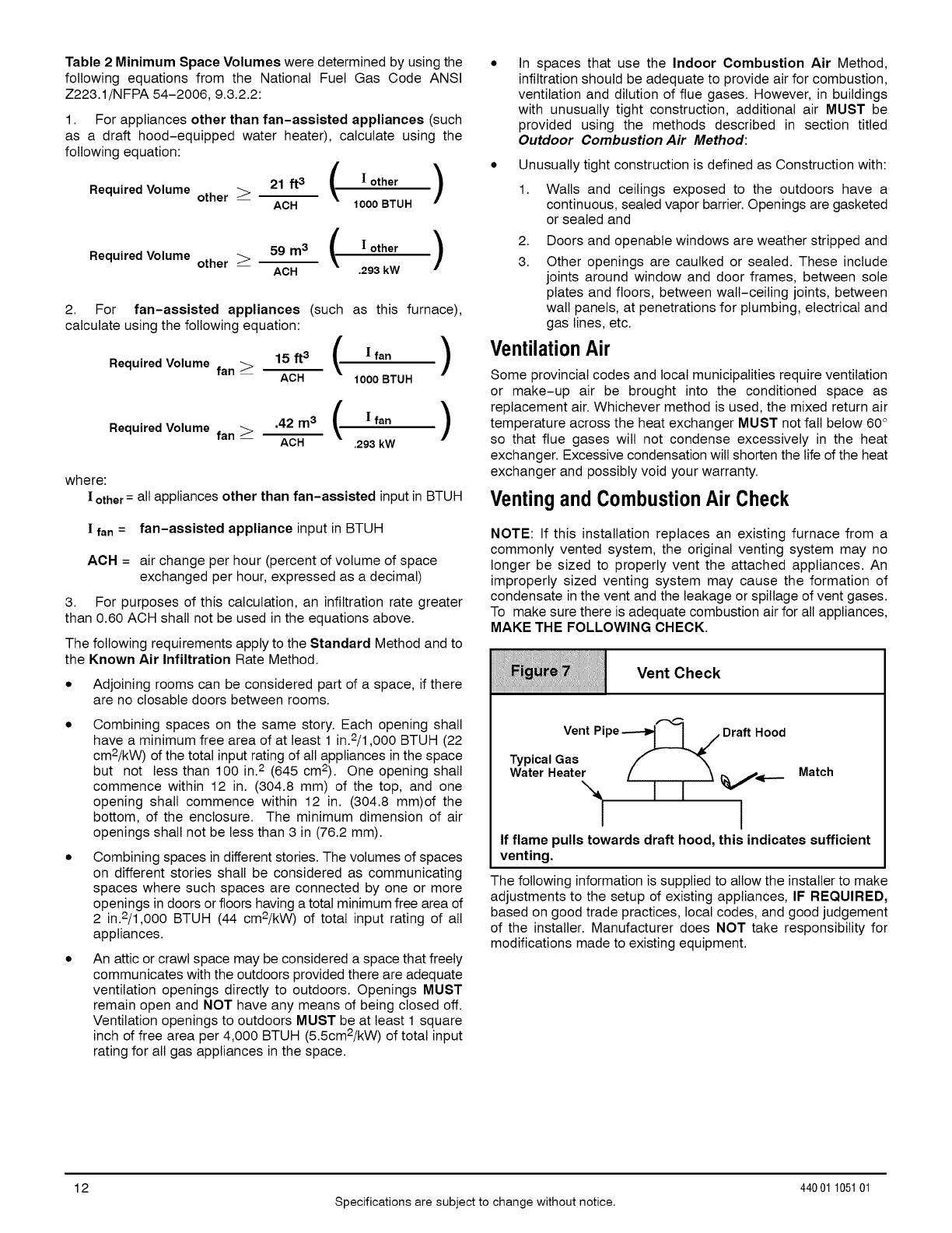
Table 2 Minimum Space Volumes were determined by using the
following equations from the National Fuel Gas Code ANSI
Z223.1/NFPA 54-2006, 9.3.2.2:
1. For appliances other than fan-assisted appliances (such
as a draft hood-equipped water heater), calculate using the
following equation:
Required Volume other _21ft3 ( |°ther )
-- ACH 1000 BTUH
/\
Required Volume other _59 m3 t! other )
-- ACH .293 kW
2. For fan-assisted appliances (such as this furnace),
calculate using the following equation:
Required Volume fan_ 15ft3 (!fen )
ACH 1000 BTUH
Required Volume fan _ .42 m3 ( ! fan /
ACH .293 kW
where:
!other=all appliances other than fan-assisted input in BTUH
!fan =fan-assisted appliance input in BTUH
ACH = air change per hour (percent of volume of space
exchanged per hour, expressed as a decimal)
3. For purposes of this calculation, an infiltration rate greater
than 0.60 ACH shall not be used in the equations above.
The following requirements apply to the Standard Method and to
the Known Air Infiltration Rate Method.
* Adjoining rooms can be considered part of a space, if there
are no ctosable doors between rooms.
Combining spaces on the same story. Each opening shall
have a minimum free area of at least 1 in.2/1,000 BTUH (22
cm2/kW) of the total input rating of all appliances in the space
but not less than 100 in.2 (645 cm2). One opening shall
commence within 12 in. (304.8 mm) of the top, and one
opening shall commence within 12 in. (304.8 mm)of the
bottom, of the enclosure. The minimum dimension of air
openings shall not be less than 3 in (76.2 mm).
Combining spaces in different stories. The volumes of spaces
on different stories shall be considered as communicating
spaces where such spaces are connected by one or more
openings in doors or floors having a total minimum free area of
2 in.2/1,000 BTUH (44 cm2/kW) of total input rating of all
appliances.
An attic or crawl space may be considered a space that freely
communicates with the outdoors provided there are adequate
ventilation openings directly to outdoors. Openings MUST
remain open and NOT have any means of being closed off.
Ventilation openings to outdoors MUST be at least 1 square
inch of free area per 4,000 BTUH (5.5cm2/kW) of total input
rating for all gas appliances in the space.
In spaces that use the Indoor Combustion Air Method,
infiltration should be adequate to provide air for combustion,
ventilation and dilution of flue gases. However, in buildings
with unusually tight construction, additional air MUST be
provided using the methods described in section titled
Outdoor Combustion Air Method:
* Unusually tight construction is defined as Construction with:
1. Walls and ceilings exposed to the outdoors have a
continuous, sealed vapor barrier. Openings are gasketed
or sealed and
2.
3.
Doors and openable windows are weather stripped and
Other openings are caulked or sealed. These include
joints around window and door frames, between sole
plates and floors, between walt-ceiling joints, between
wall panels, at penetrations for plumbing, electrical and
gas lines, etc.
VentilationAir
Some provincial codes and local municipalities require ventilation
or make-up air be brought into the conditioned space as
replacement air. Whichever method is used, the mixed return air
temperature across the heat exchanger MUST not fall below 60°
so that flue gases will not condense excessively in the heat
exchanger. Excessive condensation will shorten the life of the heat
exchanger and possibly void your warranty.
Ventingand CombustionAir Check
NOTE: If this installation replaces an existing furnace from a
commonly vented system, the original venting system may no
longer be sized to properly vent the attached appliances. An
improperly sized venting system may cause the formation of
condensate in the vent and the leakage or spillage of vent gases.
To make sure there is adequate combustion air for all appliances,
MAKE THE FOLLOWING CHECK.
VentCheck
iiiiiiiiiiiiiiiiiiiiiiiiiiiiiiiiiiiiiiiiiiiiiiiiiiiiiiiiiiiiiiiiiiiiiiiiiiiiiiiiiiiiiiiiiiiiiiiiiiiiiiiiiiiiiiiiiiiiiiiiiiiiiiiiiiiiiiiiiiiiiiiiiiii
Vent Pipe-.-_ I J Draft Hood
Typical Gas f _'_
Water Heater [_ _,<___ Match
If flame pulls towards draft hood, this indicates sufficient
venting.
The following information is supplied to allow the installer to make
adjustments to the setup of existing appliances, IF REQUIRED,
based on good trade practices, local codes, and good judgement
of the installer. Manufacturer does NOT take responsibility for
modifications made to existing equipment.
12
Specifications are subject to change without notice.
440 01 105101
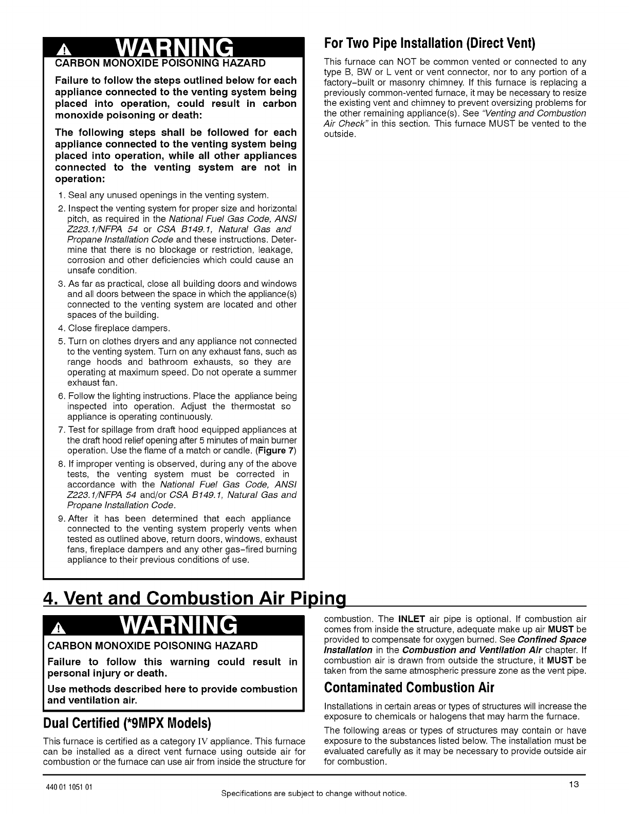
CARBON MONOXIDE POISONING HAZARD
Failure to follow the steps outlined below for each
appliance connected to the venting system being
placed into operation, could result in carbon
monoxide poisoning or death:
The following steps shall be followed for each
appliance connected to the venting system being
placed into operation, while all other appliances
connected to the venting system are not in
operation:
1. Seal any unused openings in the venting system.
2. Inspect the venting system for proper size and horizontal
pitch, as required in the National Fuel Gas Code, ANSI
Z228.1/NFPA 54 or CSA B149.1, Natural Gas and
Propane Installation Code and these instructions. Deter-
mine that there is no blockage or restriction, leakage,
corrosion and other deficiencies which could cause an
unsafe condition.
3. As far as practical, close all building doors and windows
and all doors between the space in which the appliance(s)
connected to the venting system are located and other
spaces of the building.
4. Close fireplace dampers.
5. Turn on clothes dryers and any appliance not connected
to the venting system. Turn on any exhaust fans, such as
range hoods and bathroom exhausts, so they are
operating at maximum speed. Do not operate a summer
exhaust fan.
6. Follow the lighting instructions. Place the appliance being
inspected into operation. Adjust the thermostat so
appliance is operating continuously.
7. Test for spillage from draft hood equipped appliances at
the draft hood relief opening after 5 minutes of main burner
operation. Use the flame of a match or candle. (Figure 7)
8. If improper venting is observed, during any of the above
tests, the venting system must be corrected in
accordance with the National Fuel Gas Code, ANSI
Z228.1/NFPA 54 and/or CSA B149. 1, Natural Gas and
Propane Installation Code.
9. After it has been determined that each appliance
connected to the venting system properly vents when
tested as outlined above, return doors, windows, exhaust
fans, fireplace dampers and any other gas-fired burning
appliance to their previous conditions of use.
ForTwo PipeInstallation(DirectVent)
This furnace can NOT be common vented or connected to any
type B, BW or L vent or vent connector, nor to any portion of a
factory-built or masonry chimney. If this furnace is replacing a
previously common-vented furnace, it may be necessary to resize
the existing vent and chimney to prevent oversizing problems for
the other remaining appliance(s). See "Venting and Combustion
Air Check" in this section. This furnace MUST be vented to the
outside.
4. Vent and Combustion Air Piping
CARBON MONOXIDE POISONING HAZARD
Failure to follow this warning could result in
personal injury or death.
Use methods described here to provide combustion
and ventilation air.
Dual Certified(*9MPXModels)
This furnace is certified as a category iV appliance. This furnace
can be installed as a direct vent furnace using outside air for
combustion or the furnace can use air from inside the structure for
combustion. The INLET air pipe is optional. If combustion air
comes from inside the structure, adequate make up air MUST be
provided to compensate for oxygen burned. See Confined Space
Installation in the Combustion and Ventilation Air chapter. If
combustion air is drawn from outside the structure, it MUST be
taken from the same atmospheric pressure zone as the vent pipe.
ContaminatedCombustionAir
Installations in certain areas or types of structures will increase the
exposure to chemicals or halogens that may harm the furnace.
The following areas or types of structures may contain or have
exposure to the substances listed below. The installation must be
evaluated carefully as it may be necessary to provide outside air
for combustion.
13
44001 105101 Specifications are subject to change without notice.
• Commercial buildings.
• Buildings with indoor pools.
• Furnaces installed in laundry rooms.
• Furnaces installed in hobby or craft rooms.
• Furnaces installed near chemical storage areas.
• Permanent wave solutions for hair.
• Chlorinated waxes and cleaners.
• Chlorine based swimming pool chemicals.
• Water softening chemicals.
• De-icing salts or chemicals.
• Carbon tetrachloride.
• Halogen type refrigerants.
• Cleaning solvents (such as perchloroethylene).
• Printing inks, paint removers, varnishes, etc.
• Hydrochloric acid.
• Sulfuric Acid.
• Solvent cements and glues.
• Antistatic fabric softeners for clothes dryers.
• Masonry acid washing materials.
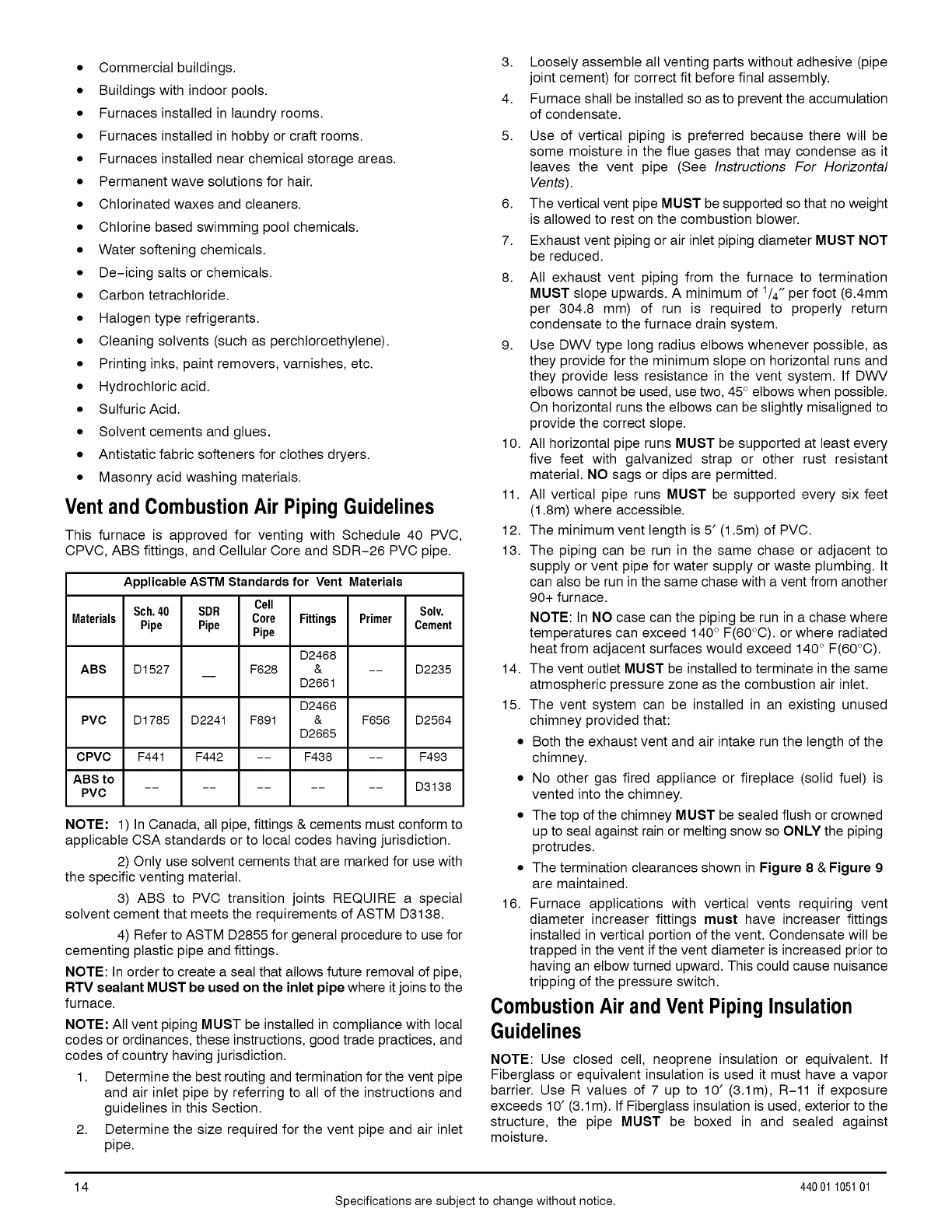
Vent and CombustionAir Piping Guidelines
This furnace is approved for venting with Schedule 40 PVC,
CPVC, ABS fittings, and Cellular Core and SDR-26 PVC pipe.
Applicable ASTM Standardsfor Vent Materials
Sch.40 SDR Cell Solv.
Materials Pipe Pipe Core Fittings Primer Cement
Pipe
D2468
ABS D1527 F628 & -- D2235
D2661
D2466
PVC D1785 D224t F891 & F656 D2564
D2665
CPVC F441 F442 -- F438 -- F493
ABS to .......... 03138
PVC
NOTE: 1) In Canada, all pipe, fittings & cements must conform to
applicable CSA standards or to local codes having jurisdiction.
2) Only use solvent cements that are marked for use with
the specific venting material.
3) ABS to PVC transition joints REQUIRE a special
solvent cement that meets the requirements of ASTM D3138.
4) Refer to ASTM D2855 for general procedure to use for
cementing plastic pipe and fittings.
NOTE: In order to create a seal that allows future removal of pipe,
RTV sealant MUST be used on the inlet pipe where it joins to the
furnace.
NOTE: All vent piping MUST be installed in compliance with local
codes or ordinances, these instructions, good trade practices, and
codes of country having jurisdiction.
1. Determine the best routing and termination for the vent pipe
and air inlet pipe by referring to all of the instructions and
guidelines in this Section.
2. Determine the size required for the vent pipe and air inlet
pipe.
3. Loosely assemble all venting parts without adhesive (pipe
joint cement) for correct fit before final assembly.
4. Furnace shall be installed so as to prevent the accumulation
of condensate.
5.
6.
7.
8.
Use of vertical piping is preferred because there will be
some moisture in the flue gases that may condense as it
leaves the vent pipe (See Instructions For Horizontal
Vents).
The vertical vent pipe MUST be supported so that no weight
is allowed to rest on the combustion blower.
Exhaust vent piping or air inlet piping diameter MUST NOT
be reduced.
All exhaust vent piping from the furnace to termination
MUST slope upwards. A minimum of 1/4" per foot (6.4mm
per 304.8 mm) of run is required to properly return
condensate to the furnace drain system.
9. Use DWV type long radius elbows whenever possible, as
they provide for the minimum slope on horizontal runs and
they provide less resistance in the vent system. If DWV
elbows cannot be used, use two, 45° elbows when possible.
On horizontal runs the elbows can be slightly misatigned to
provide the correct slope.
10. All horizontal pipe runs MUST be supported at least every
five feet with galvanized strap or other rust resistant
material. NO sags or dips are permitted.
11. All vertical pipe runs MUST be supported every six feet
(1.8m) where accessible.
12. The minimum vent length is 5' (1.5m) of PVC.
13. The piping can be run in the same chase or adjacent to
supply or vent pipe for water supply or waste plumbing. It
can also be run in the same chase with a vent from another
90+ furnace.
16.
NOTE: In NO case can the piping be run in a chase where
temperatures can exceed 140 ° F(60°C). or where radiated
heat from adjacent surfaces would exceed 140° F(60°C).
14. The vent outlet MUST be installed to terminate in the same
atmospheric pressure zone as the combustion air inlet.
15. The vent system can be installed in an existing unused
chimney provided that:
• Both the exhaust vent and air intake run the length of the
chimney.
• No other gas fired appliance or fireplace (solid fuel) is
vented into the chimney.
• The top of the chimney MUST be sealed flush or crowned
up to seal against rain or melting snow so ONLY the piping
protrudes.
The termination clearances shown in Figure 8 & Figure 9
are maintained.
Furnace applications with vertical vents requiring vent
diameter increaser fittings must have increaser fittings
installed in vertical portion of the vent. Condensate will be
trapped in the vent if the vent diameter is increased prior to
having an elbow turned upward. This could cause nuisance
tripping of the pressure switch.
Combustion Air and Vent PipingInsulation
Guidelines
NOTE: Use closed cell, neoprene insulation or equivalent. If
Fiberglass or equivalent insulation is used it must have a vapor
barrier. Use R values of 7 up to 10' (3.1m), R-11 if exposure
exceeds 10' (3.1m). If Fiberglass insulation is used, exterior to the
structure, the pipe MUST be boxed in and sealed against
moisture.
14
Specifications are subject to change without notice.
440 01 105101
1. When the vent or combustion air pipe height above the roof
exceeds 30" (76.2mm), or if an exterior vertical riser is used
on a horizontal vent to get above snow levels, the exterior
portion MUST be insulated.
2. When combustion air inlet piping is installed above a
suspended ceiling, the pipe MUST be insulated with
moisture resistant insulation such as Armaflex or other
equivalent type of insulation.
3. Insulate combustion air inlet piping when run in warm,
humid spaces.
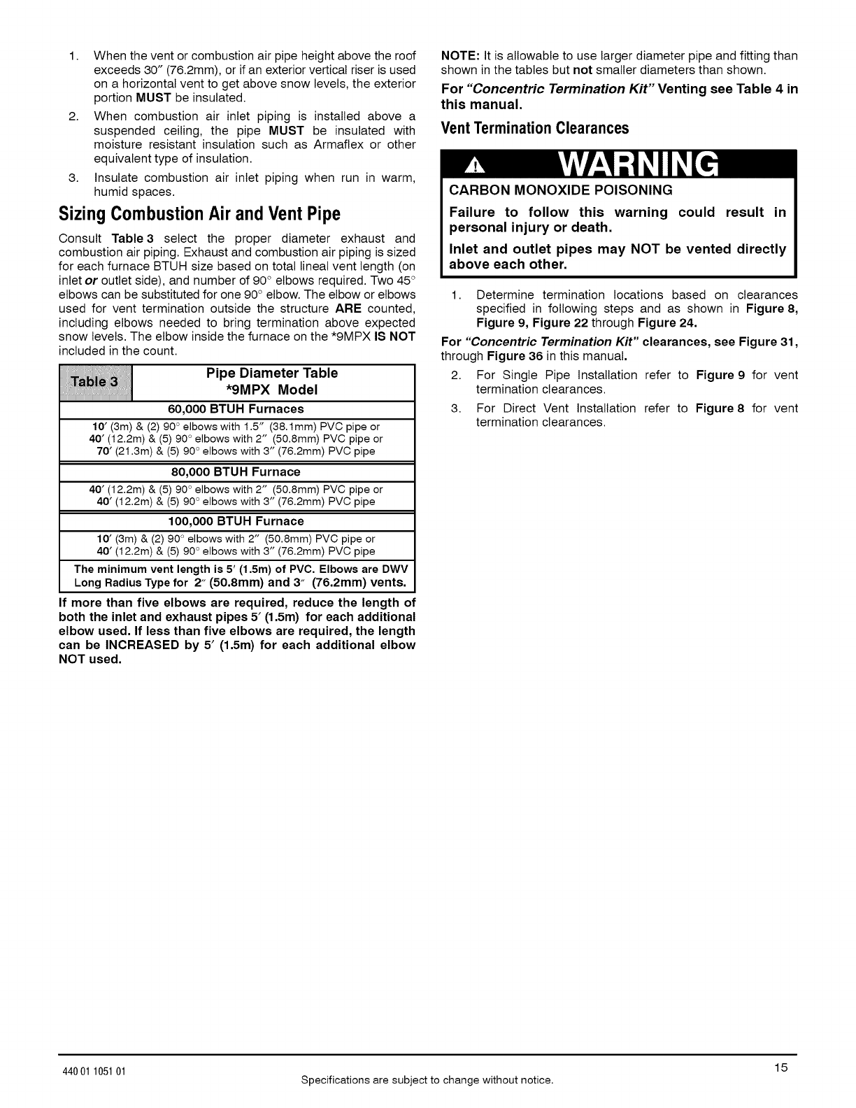
SizingCombustionAir and Vent Pipe
Consult Table3 select the proper diameter exhaust and
combustion air piping. Exhaust and combustion air piping is sized
for each furnace BTUH size based on total lineal vent length (on
inlet or outlet side), and number of 90 ° elbows required. Two 45 °
elbows can be substituted for one 90 ° elbow. The elbow or elbows
used for vent termination outside the structure ARE counted,
including elbows needed to bring termination above expected
snow levels. The elbow inside the furnace on the *9MPX IS NOT
included in the count.
Pipe Diameter Table
*9MPX Model
60,000 BTUH Furnaces
10' (3m) & (2) 90 ° elbows with 1.5" (38.1mm) PVC pipe or
40' (12.2m) & (5) 90 ° elbows with 2" (50.8mm) PVC pipe or
70' (21.3m) & (5) 90 ° elbows with 3" (76.2mm) PVC pipe
80,000 BTUH Furnace
40' (12.2m) & (5) 90 ° elbows with 2" (50.8mm) PVC pipe or
40' (12.2m) & (5) 90 ° elbows with 3" (76.2mm) PVC pipe
100,000 BTUH Furnace
10' (3m) & (2) 90 ° elbows with 2" (50.8mm) PVC pipe or
40' (12.2m) & (5) 90 ° elbows with 3" (76.2mm) PVC pipe
The minimum vent length is 5' (1,5m) of PVC, Elbows are DWV
Long Radius Type for 2" (50,8mm) and 3" (76,2mm) vents,
If more than five elbows are required, reduce the length of
both the inlet and exhaust pipes 5' (1.5m) for each additional
elbow used. If less than five elbows are required, the length
can be INCREASED by 5' (1.5m) for each additional elbow
NOT used.
NOTE: It is allowable to use larger diameter pipe and fitting than
shown in the tables but not smaller diameters than shown.
For "Concentric Termination Kit" Venting see Table 4 in
this manual.
VentTermination Clearances
CARBON MONOXIDE POISONING
Failure to follow this warning could result in
personal injury or death.
Inlet and outlet pipes may NOT be vented directly
above each other.
1. Determine termination locations based on clearances
specified in following steps and as shown in Figure 8,
Figure 9, Figure 22 through Figure 24.
For "Concentric Termination Kit" clearances, see Figure 31,
through Figure 36 in this manual.
2. For Single Pipe Installation refer to Figure 9 for vent
termination clearances.
3. For Direct Vent Installation refer to Figure 8 for vent
termination clearances.
15
44001 105101 Specifications are subject to change without notice.

Figure 8 Direct Vent Termination Clearance
_AIR SUPPLY INLET AREA WHERE TERMINAL IS NOT PERMITED
_ VENTTERMINAL \\\\\
Item Clearance Description Canadian Installation (1) U.S. Installation (2)
A Clearance above grade, veranda, porch, deck, balcony, or 12 inches(SO cm) # 12 inches (30 cm)
anticipated snow level
B Clearance to a window or door that may be opened 12 inches (30 cm) for appliances > 10,000 Btuh (3 kW) 9 inches (23 cm) for appliances > 10,000 Btuh (3kW) and
and s 100,000 Stub(30 kW), 36 inches 50_000 Btuh (15kW), 12 inches (3Ocm) for appliances >
(91 cm) for appliances > 100,000 Btuh (30 kW) 50,000 Btuh (15kW)
C Clearance to a permanently closed window
D Vertical clearance to a ventilated soffit located above the
terminal within a horizontal distance of 2 feet(61cm) from the
centerline of the terminal
E Clearance to an unven_lated soffit
F Clearance to an outside corner
G Clearance to an inside corner
H Clearance to each side of the centerline extended above 3 feet (91 cm) withln 15feet (4.5 m) above the meter/regulator 3 feet (91 cm) within 15 feet (4.5 m) above the
electrical meter or gas service regulator assembly assembly meter/regulator assembly
I Clearance to service regulator vent oilier 3 feet (91 cm)
J Clearance to non-mechanical air supply inlet to building or 12 inches (23 cm) for appliances > 100,000 Btuh (3 kW) 9 inches (23 cm) for appliances > 1O,00OStab (3kW) and
the combustion air inlet to any other appliance and s 100,000 Btuh (30 kW), 36 inches (30 cm) for _ 50,000 Btuh (15kW), 12 inches (30cm) for appliances
appliances > 100,000 Btuh (3 kW) > 50,000 Btah (15kW)
K Clearance to a mechanical air supply inlet 6 feet (1.83 m) 3 feet (91cm) above it within 10 feet (3m)hodzontally
L Clearance under a veranda, porch, deck, or balcony 12 inches(30 cm} +
M Clearance toeach side of the centerline extended above or 12 inches (30 cm) 12 inches (30 cm)
below vent terminal of the furnace to a dryer or water heater
vent, or other appliance's direct vent intake or exhaust.
N Clearance to the vent terminal of e dryer vent, water heater 3 feet (91 cm) 3 feet (91 em)
vent, or other appliances direct vent intake or exhaust.
O Clearance from a plumbing vent stack 3 feet (91 cm) 3 feet (91 cm)
p Clearance above paved sidewalk or paved 7 feet (2.13m)**
driveway located on public property
(t.) In accordance with the current CSA B149.1, Natural Gas and Propane Installation Code
(2.) In accordance with the current ANSI Z223.1/NFPA 54, National Fuel Gas Code
# 18" (46cm)aboveroofsurface
+Permitted only if veranda, porch, deck, or balcony is fully open on a minimum of two sides beneath the floor.
For clearances not specified in ANSI Z223.1/NFPA 54 or CSA B149.1, clearances shall be in accordance with local installation codes and the requirements of the gas supplier and the
manufacturer's installation instructions
A vent shall not terminate above a sidewalk or paved driveway that is located between two single family dwellings and serves both dwellings.
Notes:
1,
2,
3.
16
The vent for this appliance shall not terminate
a. Over public walkways; or
b. Near soffit vents or crawl space vents or other areas where condensate or vapor could create a nusaince or hazard or property damage; or
c. Where condansate vapor could cause damage or could be detrimental to the operation of reg£,laters, relief valves, or other equipmenL
When locating vent terminations, consideration mast be given to prevailing winds, location, and other conditions which may cause recirculation of the combustion products of adjacent vents.
Recircalation can cause poor combustion, inlet condensate problems, and accelerated corrosion of the heat exchangers.
Avoid venting under a deck or large overhang. Recirculation could occur and cause performance or system problems.
440 01 105101
Specifications are subject to change without notice.
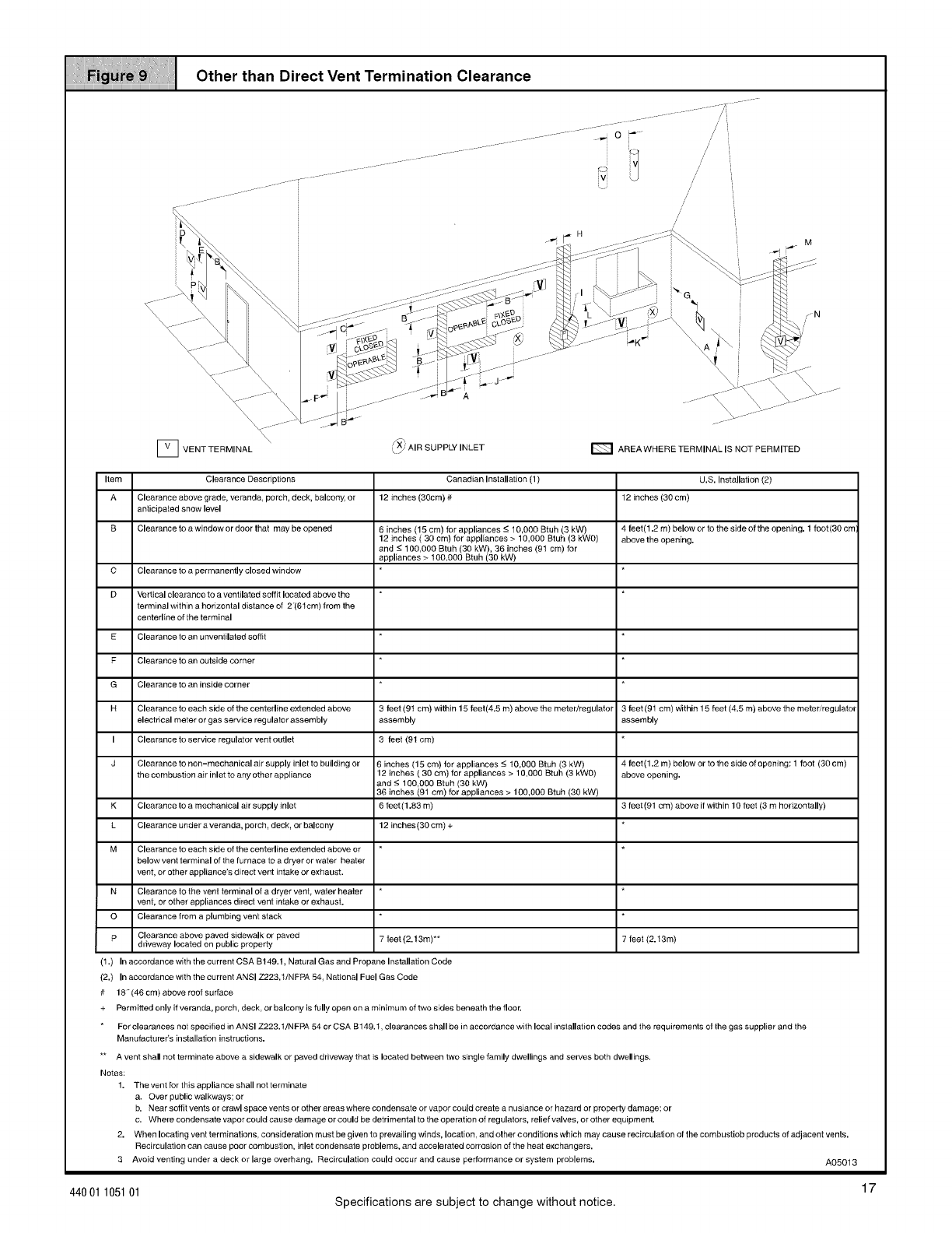
Other than Direct Vent Termination Clearance
/
r'
/
[] VENTTERMINAL \_ L_ AIR SUPPLY INLET E_ AREAWHERE TERMINAL IS NOT PERMITED
Item Clearance Descriptions
A Clearance above grade, veranda, porch, deck, balcony, or
anticipated snow level
B Clearance to a window or door that may be opened
K
L
M
C Clearance to a permanently closed window
D Vertical clearance to a ventilated soffit located above the
terminal within a horizontal distance of 2"(61cm) from the
centerline of the terminal
E Clearance to an unventilated soffit
F Clearance to an outside corner
G Clearance to an inside corner
H Clearance to each side of the centerline extended above
electrical meter or gas service regulator assembly
I Clearance to service regulator vent outlet
J Clearance to non-mechanical air supply inlet to building or
the combustion air inlet to any other appliance
Clearance to a mechanical air supply inlet
Clearance under a veranda, porch, deck, or balcony
Canadian Installation (1)
12 inches (30cm) #
6 inches 15 cm) for appliances -< 10,000 Btuh (3 kW)
12 inches 30 cm) for app ances > 10000 Btuh (3 kWO)
and -< 100,000 Btuh 30 kW), 36 inches (91 cm) for
app iances > t00,000 Btuh (30 kW)
3feet (9t cm) within 15 feet(4.5 m) above the meter/regulator
assembly
3 feet (91 cm)
6 inches (15 cm) for appliances -< I0,000 Btuh (3 kW)
12 inches ( 30 cm) for appliances > 10,OOO Btuh (3 kWO)
and -< 1O0,0OO Btuh (30 kW)
36 inches (91 cm) for appliances > 100,000 Stuh (30 kW)
6 feet(I.83 m)
12 inches(30 cm) +
Clearance to each side of the centerline extended above or
below vent terminal of the furnace to a dryer or waler heater
vent, or other appliance's direct vent intake or exhaust.
N Clearance to the vent terminal of a dryer vent, water heater
vent, or other appliances direct vent intake or exhaust.
O Clearance from a plumbing vent stack
F' Clearance above paved sidewalk or paved 7 feet (2.13m)**
driveway located on public property
(1.) In accordance with the current CSA B149.t, Natural Gas and Propane Installation Code
(2.) In accordance with the current ANSI Z223.1/NFPA 54, National Fuel Gas Code
# 18" (46 cm) above roof surrace
U.S. Installation (2)
12 inches (30 cm)
4 feet(1.2 m) below or to the side of the opening. 1 foot(30 cm)
above the opening.
3 feet (91 cm) _iithin 15 feet (4.5 m) above the meter/regulator
assembly
4 feet(1.2 m) below or to the side of opening: 1 foot (30 cm)
above opening.
3 feet (91 cm) above if within 10 feet (3 m horizontally)
7feet (2.t3m)
+ Permitted only if veranda, porch, deck, or balcony is fully open on a minimum of two sides beneath the floor.
For clearances not specified in ANSI Z223.1/NFPA 54 or CSA B149. t, clearances shall be in accordance with local installation codes and the requirements of the gas supplier and the
ManufactureCs installation instructions.
** A vent shall not terminate above a sidewalk or paved driveway that is located between two single family dwellings and serves both dwellings.
Notes:
1. The vent for this appliance shall not terminate
a. Over public walkways; or
b. Near soffit vente or crawl space vents or other areas where condensate or vapor could create a nusiance or hazard or property damage; or
e. Where condensate vapor could cause damage or could be detrimental to the operation of regulators, relief valves, or other equipment.
2. When locating vent terminations, consideration must be given to prevailing winds, location, and other c onditions which may cause recireulation ofthe combustiob products of adjacent vents.
Reeirculation can cause poor combustion, inlet condensate problems, and accelerated corrosion ofthe heat exchangers.
3 Avoid venting under a deck or large overhang. Reeirculation could occur arrd cause performance or system problems. A05013
17
44001 105101 Specifications are subject to change without notice.
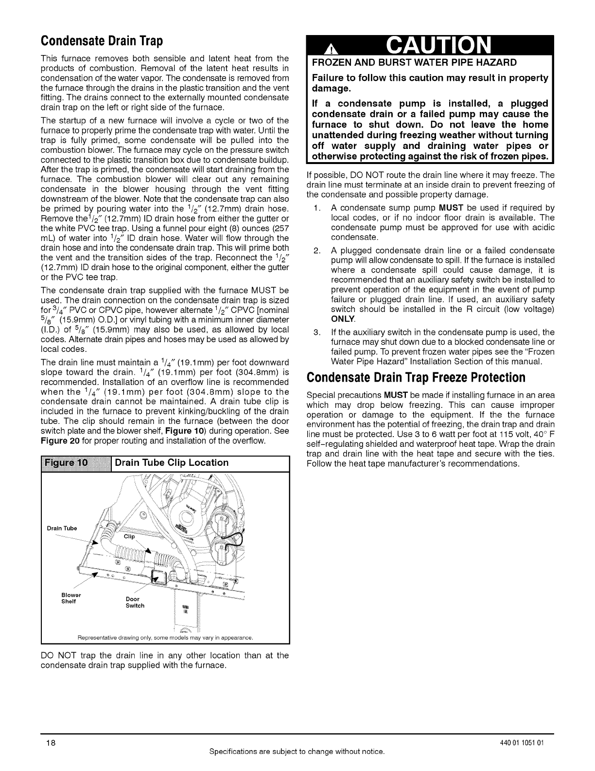
CondensateDrainTrap
This furnace removes both sensible and latent heat from the
products of combustion. Removal of the latent heat results in
condensation of the water vapor. The condensate is removed from
the furnace through the drains in the plastic transition and the vent
fitting. The drains connect to the externally mounted condensate
drain trap on the left or right side of the furnace.
The startup of a new furnace will involve a cycle or two of the
furnace to properly prime the condensate trap with water. Until the
trap is fully primed, some condensate wilt be pulled into the
combustion blower. The furnace may cycle on the pressure switch
connected to the plastic transition box due to condensate buildup.
After the trap is primed, the condensate will start draining from the
furnace. The combustion blower will clear out any remaining
condensate in the blower housing through the vent fitting
downstream of the blower. Note that the condensate trap can also
be primed by pouring water into the 1/2" (12.7mm) drain hose.
Remove the1/2 " (12.7mm) ID drain hose from either the gutter or
the white PVC tee trap. Using a funnel pour eight (8) ounces (257
mL) of water into 1/2" ID drain hose. Water wilt flow through the
drain hose and into the condensate drain trap. This will prime both
the vent and the transition sides of the trap. Reconnect the 1/2"
(12.7mm) ID drain hose to the original component, either the gutter
or the PVC tee trap.
The condensate drain trap supplied with the furnace MUST be
used. The drain connection on the condensate drain trap is sized
for 3/4" PVC or CPVC pipe, however alternate 1/2" CPVC [nominal
5/8" (15.9mm) O.D.] or vinyl tubing with a minimum inner diameter
(I.D.) of 5/8" (15.9mm) may also be used, as allowed by local
codes. Alternate drain pipes and hoses may be used as allowed by
local codes.
The drain line must maintain a 1/4" (19.1 mm) per foot downward
slope toward the drain. 1/4" (19.1mm) per foot (304.8mm) is
recommended. Installation of an overflow line is recommended
when the 1/4" (19.1mm) per foot (304.8mm) slope to the
condensate drain cannot be maintained. A drain tube clip is
included in the furnace to prevent kinking/buckling of the drain
tube. The clip should remain in the furnace (between the door
switch plate and the blower shelf, Figure 10) during operation. See
Figure 20 for proper routing and installation of the overflow.
Fi_} _0 !,i,iI ] Drain Tube Clip Location
Drain Tube
Blower
Shelf Door
Switch
Representativedrawing only, some models may vary in appearance.
DO NOT trap the drain line in any other location than at the
condensate drain trap supplied with the furnace.
FROZEN AND BURST WATER PIPE HAZARD
Failure to follow this caution may result in property
damage.
If a condensate pump is installed, a plugged
condensate drain or a failed pump may cause the
furnace to shut down. Do not leave the home
unattended during freezing weather without turning
off water supply and draining water pipes or
otherwise protecting against the risk of frozen pipes.
If possible, DO NOT route the drain line where it may freeze. The
drain line must terminate at an inside drain to prevent freezing of
the condensate and possible property damage.
1. A condensate sump pump MUST be used if required by
local codes, or if no indoor floor drain is available. The
condensate pump must be approved for use with acidic
condensate.
2.
3.
A plugged condensate drain line or a failed condensate
pump will atlowcondensate to spill. If the furnace is installed
where a condensate spill could cause damage, it is
recommended that an auxiliary safety switch be installed to
prevent operation of the equipment in the event of pump
failure or plugged drain line. If used, an auxiliary safety
switch should be installed in the R circuit (low voltage)
ONLY.
If the auxiliary switch in the condensate pump is used, the
furnace may shut down due to a blocked condensate line or
failed pump. To prevent frozen water pipes see the "Frozen
Water Pipe Hazard" Installation Section of this manual.
CondensateDrainTrap FreezeProtection
Special precautions MUST be made if installing furnace in an area
which may drop below freezing. This can cause improper
operation or damage to the equipment. If the the furnace
environment has the potential of freezing, the drain trap and drain
line must be protected. Use 3 to 6 watt per foot at 115 volt, 40° F
self-regulating shielded and waterproof heat tape. Wrap the drain
trap and drain line with the heat tape and secure with the ties.
Follow the heat tape manufacturer's recommendations.
18
Specifications are subject to change without notice.
440 01 105101
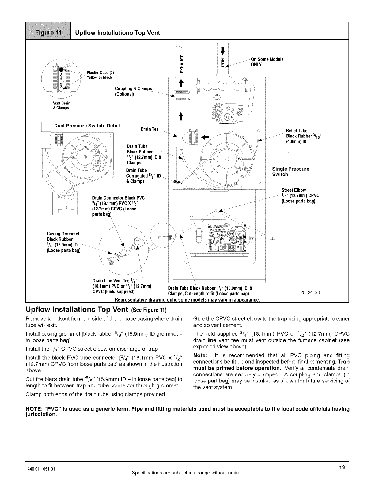
Miiiiiiiiiiii_:iii1iii_IH!_i;;;iii_iiiii111Iiii!!ii_ii!ii_ii`_iiiiiiiii!iiiii1iiHii!ii1iiiI_iiiii_iii11i!iiiiii
Upflow Installations Top Vent
iiiiiiiiiiiiiiiiiiiiiiiiiiiiiiiiiiiiiiiiiiiiiiiiiiiiiiiiiiiiiiiiiiiiiiiiiiiiiiiiiiiiiiiiiiiiiiiiiiiiiiiiiiiiiiiiiiiiiiiiiiiiiiiiiiiiiiiiiiiiiiii
) ,x,;
i_/ Coupling&Clamps
._ ........ (Optional)
Vent Drain
& Clamps
i .....OnSomeModels
r- _ .......
rn _...... ONLY
_:-\" Y' J\_Y EJ
ReliefTube
..............BlackRubber3/16"
(4.8mm)ID
Single Pressure
Switch
Street Elbow
.........1/2"(12,7mm)CPVC
(Loosepartsbag)
(18.1mm)PVCor 1/2" (12,7mm) DrainTubeBlackRubber/8 (15.9mm)ID &
CPVC(Fieldsupplied) Clamps,Cutlengthtofit (Loosepartsbag)
Representativedrawingonly,somemodelsmayvaryinappearance.
25-24-80
Upflow Installations Top Vent (SeeFigure11)
Remove knockout from the side of the furnace casing where drain
tube will exit. Glue the CPVC street elbow to the trap using appropriate cleaner
and solvent cement.
Install casing grommet [black rubber 5/8" (15.9mm) ID grommet-
in loose parts bag]
Install the 1/2" CPVC street elbow on discharge of trap
Install the black PVC tube connector [3/4" (18.1mm PVC x 1/2"
(12.7mm) CPVC from loose parts bag] as shown in the illustration
above.
Cut the black drain tube [5/8" (15.9mm) ID -in loose parts bag] to
length to fit between trap and tube connector through grommet.
Clamp both ends of the drain tube using clamps provided.
The field supplied 3/4" (18.1mm) PVC or 1/2" (12.7mm) CPVC
drain line vent tee must vent outside the furnace cabinet (see
exploded view above),
Note: It is recommended that all PVC piping and fitting
connections be fit up and inspected before final cementing. Trap
must be primed before operation, Verify all condensate drain
connections are securely clamped. A coupling and clamps (in
loose part bag) may be installed as shown for future servicing of
the vent system.
NOTE: "PVC" is used as a generic term. Pipe and fitting materials used must be acceptable to the local code officials having
jurisdiction.
19
44001 105101 Specifications are subject to change without notice.

iiiiii_iiiiiiiiii_:iii]i_]_IH!_i_;_iii_iiiii111Iiii!!ii_]i!ii_ii`_iiiiiiii!iiiii1ii_i_!_iI_!!i_iiIiii!iii_iii`i_iii_
Upflow Installations Vent through Left Side
iiiiiiiiiiiiiiiiiiiiiiiiiiiiiiiiiiiiiiiiiiiiiiiiiiiiiiiiiiiiiiiiiiiiiiiiiiiiiiiiiiiiiiiiiiiiiiiiiiiiiiiiiiiiiiiiiiiiiiiiiiiiiiiiiiiiiiiiiiiiiiiiiiii
Plastic Cap
Yellow or black
J
Coupling& Clamps
(Optional)......
Either:ThePVC
2"(50,8mm)PVC
Coupling
t
..... OnSomeModels
::- z ......
_,wrv ONLY
DrainLineVentTee3/4" (18,1mm)PVCor1/2"' [ i 25-24-81
(12,7mm)CPVC(Fieldsupplied) Representativedrawingonly,somemodelsmayvaryinappearance.
Upflow Installations Vent through Left Side (SeeFigure12)
Remove drain tee from inducer discharge and remove black drain Cut the black drain tube [5/8" (15.9mm) ID -in loose parts bag] to
tube 1/2" (12.7mm) ID from bottom of drain tee. length to fit between trap and tube connector through grommet.
Install Vent Pipe grommet in side of casing. Clamp both ends of the drain tube using clamps provided.
Cut an appropriate length of 2" (50.8mm) PVC pipe long enough Glue the CPVC street elbow to the trap using appropriate cleaner
to exit the cabinet and connect the vent drain to either: and solvent cement.
• A standard field supplied 2" (50.8mm) PVC tee, or
• A 2" (50.8mm) PVC coupling fastened onto the drain tee.
Install tee trap into bottom of tee.
Remove knockout from the side of the furnace casing where drain
tube will exit.
Install the 1/2" (12.7mm) CPVC street elbow on discharge of trap
Install the black PVC drain connector [3/4" (19.1mm) PVC x 1/2"
CPVC from loose parts bag] as shown in the illustration above.
Connect the tee trap and the main drain line exiting the casing as
shown in Figure 20.
Note: It is recommended that all PVC piping and fitting
connections be fit up and inspected before final cementing. Both
the internal trap and the external tee trap must be primed
before operation, Verify all condensate drain connections are
securely clamped. A coupling and clamps (in loose part bag) may
be installed as shown for future servicing of the vent system.
20
Specifications are subject to change without notice.
440 01 105101
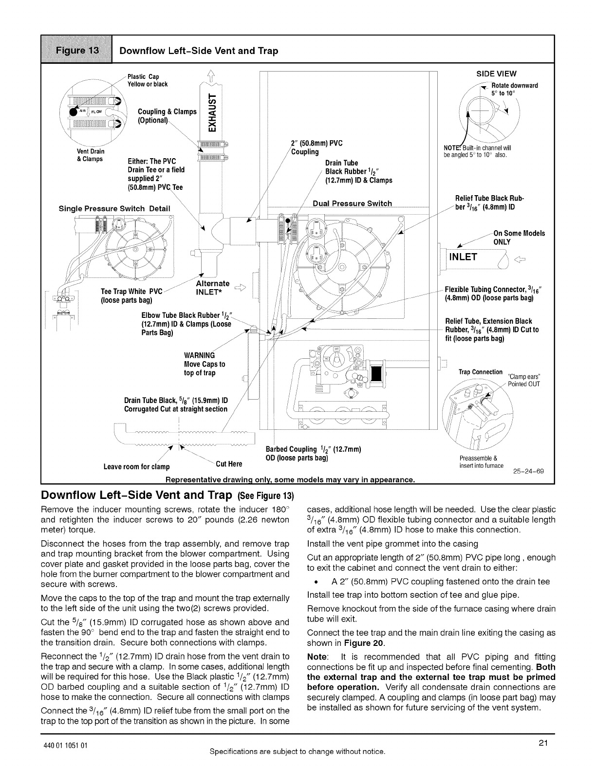
_i_i_i_iii1_7_i_i_i_i1_{_itti_i_i_;i_i_i_i1_ii_!_!i`i7i{i_!_1i_i_i7iii!_i!iiiII!iiitii_7i7!i_i_i7_11i_
t! oown.ow.e,t-SideVan,ondZro
________________________________________________________________________________________________________________________________________________
........... . /Pastc Cap /_ i SIDE VIEW
/-"__ Rotate downward
Yellow or black :'\/'h
/-r_ "rl_ \ _ /5° t°10°
,' =i _ ...... .., i ' ,'//_'.. ......
i _""i;'_°N _;i \, Coupling&Clamps ,=a:: : _ i; -_
_Vent:Drl i ;_' (optional)_ __ /_°(uSl:i:m m) PVC beNOTE_B" uilt-in channelwill
i _ P g angled 5°to 10° also.
&Clamps Either:ThePVC '_!J_J_ _ // DrainTube
DrainTeeora field 7 i _ //BlackRubber1/2"
supplied2" ii i i/ // (12,7mm)lD&Clamps
(50.8mm)PV_e _ i/ //
iReliefTubeBlackRub-
Single Pressure Switch Detail _\ _ ..................................... .........................................................Fber 3/16"(4.8mm)ID
° _ ............................ /. _ r<_ ,
%_.__, _ _:,_ _E)__ .. _ j..._OnSomeaodels
A /// t_ /",_- ''¢........ ,
:// ;:,.............................z>___..,_/ ..............._ .............- iii //',.'.. ',.T _// // 7 ........
/(__¢'...... ..............Alternate __> /.'/_\ '_"" ......_'_/' /7
i::4 TeeTrapWhitePVC/ INLET* _ i // i _ ._-_;' i ........ FlexibleTubingC°nnect°r'3/16"
77t_ (loosepartsbag) i/"_ i _" _/_ . . ....... (4.8mm)OD(loosepartsbag)
;_'_q EIb°wTubeBlackRubber1/2"---- i];iii _'!
i ;; (12.7mm)ID&Clamps(Loose ......._i i_ ..... ReliefTube,ExtensionBlack
PartsBag) /_':_ _-;-_/;_?_ .........Rubber,3/16"(4"8mm)IDCuttO
_ _/__i-_/_-: fit (loosepartsbag)
WARNING /_J,7"iC_"' '_''_
MoveCapsto /,,/_"'_oL,"'. _, \. _.,_:_=./_)_ ..................................................................................
top of trap J i ]i h,_ c ,O _}_i ! ;.......TrapConnection _.
........ <'ulampears"
,/ <_ )_ /_:.<._r-._ _ PointedOUT
DrainTubeBlack,518"(15,9mm)ID /i:'/ ,,'z S,\ '.....
CorrugatedCutatstraightsection/, /ii \"[7: /__'_ /_ _\_:::::::_ _) iii.,,_./._i,,_'._,'-.. i
................. i/' ......
....................................................................................BarbedCouplingt/2(12,7mm) _' )''
_"_- _ OD(loosepartsbag) Preassemble&
Leaveroomfor clamp CutHere insertintofurnace 25-24-69
Representative drawing only, some models may vary in appearance,
Downflow Left-Side Vent and Trap (SeeFigure13)
Remove the inducer mounting screws, rotate the inducer 180 °
and retighten the inducer screws to 20" pounds (2.26 newton
meter) torque.
cases, additional hose length will be needed. Use the clear plastic
3/16" (4.8mm) OD flexible tubing connector and a suitable length
of extra 3/16" (4.8mm) ID hose to make this connection.
Disconnect the hoses from the trap assembly, and remove trap
and trap mounting bracket from the blower compartment. Using
cover plate and gasket provided in the loose parts bag, cover the
hole from the burner compartment to the blower compartment and
secure with screws.
Move the caps to the top of the trap and mount the trap externally
to the left side of the unit using the two(2) screws provided.
Cut the 5/8" (15.9mm) ID corrugated hose as shown above and
fasten the 90 ° bend end to the trap and fasten the straight end to
the transition drain. Secure both connections with clamps.
Reconnect the 1/2" (12.7mm) ID drain hose from the vent drain to
the trap and secure with a clamp. In some cases, additional length
will be required for this hose. Use the Black plastic 1/2" (12.7mm)
OD barbed coupling and a suitable section of 1/2" (12.7mm) ID
hose to make the connection. Secure all connections with clamps
Connect the 3/16" (4.8mm) ID relief tube from the small port on the
trap to the top port of the transition as shown in the picture. In some
Install the vent pipe grommet into the casing
Cut an appropriate length of 2" (50.8mm) PVC pipe long, enough
to exit the cabinet and connect the vent drain to either:
• A 2" (50.8mm) PVC coupling fastened onto the drain tee
Install tee trap into bottom section of tee and glue pipe.
Remove knockout from the side of the furnace casing where drain
tube will exit.
Connect the tee trap and the main drain line exiting the casing as
shown in Figure 20.
Note: It is recommended that all PVC piping and fitting
connections be fit up and inspected before final cementing. Both
the external trap and the external tee trap must be primed
before operation, Verify all condensate drain connections are
securely clamped. A coupling and clamps (in loose part bag) may
be installed as shown for future servicing of the vent system.
21
44001 105101 Specifications are subject to change without notice.
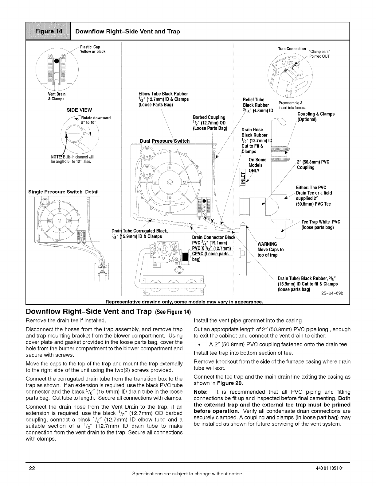
iiiiii_iiiiiiiii!iiiYiiiiiii1_iiiiii_iiIIIIiiii_iiiii!!i_iiiiiHiiii;ii_iii_iiiiiiii_iiiiiiii_Iiiiiiiiii11_ii!iiiIIii_i_iiii!
l Oown.owR,ght-S,deVentondZrop
iiiiiiiiiiiiiiiiiiiiiiiiiiiiiiiiiiiiiiiiiiiiiiiiiiiiiiiiiiiiiiiiiiiiiiiiiiiiiiiiiiiiiiiiiiiiiiiiiiiiiiiiiiiiiiiiiiiiiiiiiiiiiiiiiiiiiiiiiiiiiiii
Downflow Right-Side Vent and Trap (SeeFigure
Remove the drain tee if installed.
Disconnect the hoses from the trap assembly, and remove trap
and trap mounting bracket from the blower compartment. Using
cover plate and gasket provided in the loose parts bag, cover the
hole from the burner compartment to the blower compartment and
secure with screws.
Move the caps to the top of the trap and mount the trap externally
to the right side of the unit using the two(2) screws provided.
Connect the corrugated drain tube from the transition box to the
trap as shown. If an extension is required, use the black PVC tube
connector and the black 5/8" (15.9mm) ID drain tube inthe loose
parts bag. Cut tube to length. Secure all connections with clamps.
Connect the drain hose from the Vent Drain to the trap. If an
extension is required, use the black 1/2" (12.7mm) OD barbed
coupling, connect a black 1/2" (12.7mm) ID elbow tube and a
suitable section of a 1/2" (12.7mm) ID drain tube to make
connection from the vent drain to the trap. Secure all connections
with clamps.
14)
Install the vent pipe grommet into the casing
Cut an appropriate length of 2" (50.8mm) PVC pipe long, enough
to exit the cabinet and connect the vent drain to either:
• A 2" (50.8mm) PVC coupling fastened onto the drain tee
Install tee trap into bottom section of tee.
Remove knockout from the side of the furnace casing where drain
tube will exit.
Connect the tee trap and the main drain line exiting the casing as
shown in Figure 20.
Note: It is recommended that all PVC piping and fitting
connections be fit up and inspected before final cementing. Both
the external trap and the external tee trap must be primed
before operation, Verify all condensate drain connections are
securely clamped. A coupling and clamps (in loose part bag) may
be installed as shown for future servicing of the vent system.
22
Specifications are subject to change without notice.
440 01 105101
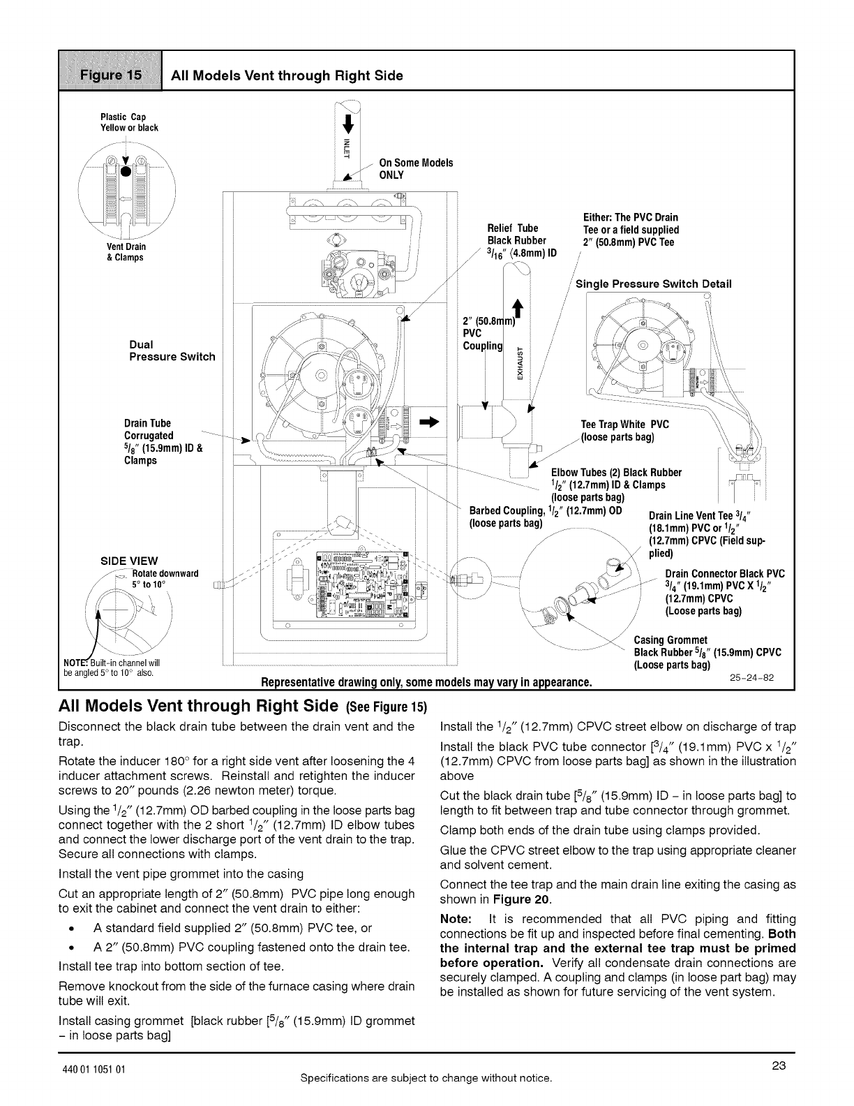
/i/ii///il;ii//i!!iiiiiil;iiii//i/il/i/lii!lilii'ii!itiii!!i!iii:iii/i'i//i
......L.i Ift. ventt,ro, , ==.
Plastic Cap #Yellowor black
SIDE VIEW
_--_i Rotate downward
5°to 10°
be angled 5° to 10° also.
.... _. _ DrainLineVentTee3/4"
j j _...........................................i_'_S" . j_ loose parzsnag/ ....... ----. (18.1mm)PVCor 1/2"
j j o"" "'C-. J_i _" \\ (12.7mm)CFVC(Fieldsup-
J-'_-" ,..............,_.', _-'u ; ;, ! /_plied)
.--- ,_,_ _i_,_.__,0 _ "_- _ /_._:./\
D_ -" i ] _ _,,._)j_'_t _L.,0 i- ."_\'_,- _ ,........................' _ _.. .... DranConnectorBackPVC
i ......................................................................................................................................................_ _ _._._ CasingGrommet
j j - ......... _ BlackRubber5/8.(15.9mm)CPVC
(Loosepartsbag)
Representativedrawingonly,somemodelsmayvaryinappearance. 25-24-82
All Models Vent through Right Side (SeeFigure15)
Disconnect the black drain tube between the drain vent and the
trap.
Rotate the inducer 180° for a right side vent after loosening the 4
inducer attachment screws. Reinstall and retighten the inducer
screws to 20" pounds (2.26 newton meter) torque.
Using the 1/2" (12.7mm) OD barbed coupling in the loose parts bag
connect together with the 2 short 1/2" (12.7mm) ID elbow tubes
and connect the lower discharge port of the vent drain to the trap.
Secure all connections with clamps.
Install the vent pipe grommet into the casing
Cut an appropriate length of 2" (50.8mm) PVC pipe long enough
to exit the cabinet and connect the vent drain to either:
• A standard field supplied 2" (50.8mm) PVC tee, or
• A 2" (50.8mm) PVC coupling fastened onto the drain tee.
Install tee trap into bottom section of tee.
Remove knockout from the side of the furnace casing where drain
tube will exit.
Install the _/2" (12.7mm) CPVC street elbow on discharge of trap
Install the black PVC tube connector [3/4" (19.1mm) PVC x _/2"
(12.7mm) CPVC from loose parts bag] as shown in the illustration
above
Cut the black drain tube [5/8" (15.9mm) ID - in loose parts bag] to
length to fit between trap and tube connector through grommet.
Clamp both ends of the drain tube using clamps provided.
Glue the CPVC street elbow to the trap using appropriate cleaner
and solvent cement.
Connect the tee trap and the main drain line exiting the casing as
shown in Figure 20.
Note: It is recommended that all PVC piping and fitting
connections be fit up and inspected before final cementing. Both
the internal trap and the external tee trap must be primed
before operation. Verify all condensate drain connections are
securely clamped. A coupling and clamps (in loose part bag) may
be installed as shown for future servicing of the vent system.
Install casing grommet [black rubber [5/8" (15.9mm) ID grommet
- in loose parts bag]
23
44001 105101 Specifications are subject to change without notice.

iiiiiiiiiiiiiiiii_;iiiii!ii!_iii1ii!iiii_iii_;i_;iii_iii!iHiiiii_iiiiiiiii:i_iiii!!i_iii_ii_ii1iiiii_iiiiii!i_iiii!!ii!
Vent Drain
& Clamps
Horizontal Left through Top
Plastic Caps Single Pressure Switch Detail
' L
Alternate Orientation
.....j I1_
Dual Pressure Switch
i
ReliefTubeBlackRubber
3/16" (4.8mm)ID
Trap Connection
Preassemble&
insertinto furnace
(loosepartsbag)
Representativedrawingonly,somemodelsmayvaryinappearance.
Horizontal Left through Top (SeeFigure16)
Disconnect the hoses from the trap assembly, and remove trap
and trap mounting bracket from the blower compartment. Using
cover plate and gasket provided in the loose parts bag, cover the
hole from the burner compartment to the blower compartment and
secure with screws.
Remove knockout from the side of the furnace casing where drain
tube will exit.
Mount the trap externally to the bottom side of the unit using the
two screws provided in the location shown.
Cut the corrugated tube as shown in the illustration above.
Connect the corrugated hose from the transition to the trap.
Secure connections with clamps.
Remove the black 1/2" (12.7mm) ID drain tube from the drain tee.
Install a yellow cap and clamp over the open drain port of the drain
tee.
Connect the black 1/2" (12.7mm) ID drain tube from the Vent Drain
to the trap. Secure connections with clamps.
25-24-84
Connect the 3/16" (4.8mm) ID relief tube to the middle port on the
trap. If an extension is required, use the 3/16" (4.8mm) OD flexible
tubing connector and the black 3/16" (4.8mm) ID relief tube in the
loose parts bag. Cut tube to length. Secure all connections with
clamps.
Cut an appropriate length of 2" (50.8mm) PVC pipe, long enough
to exit the cabinet and connect the vent drain to either:
• A standard field supplied 2" (50.8mm) PVC tee, or
• A 2" (50.8mm) PVC coupling fastened onto the drain tee.
Install tee trap into bottom section of tee.
Connect the tee trap and the main drain line exiting the casing as
shown in Figure 20.
Note: It is recommended that all PVC piping and fitting
connections be fit up and inspected before final cementing. Both
the external trap and the external tee trap must be primed
before operation, Verify all condensate drain connections are
securely clamped. A coupling and clamps (in loose part bag) may
be installed as shown for future servicing of the vent system.
24 440 01 105101
Specifications are subject to change without notice.
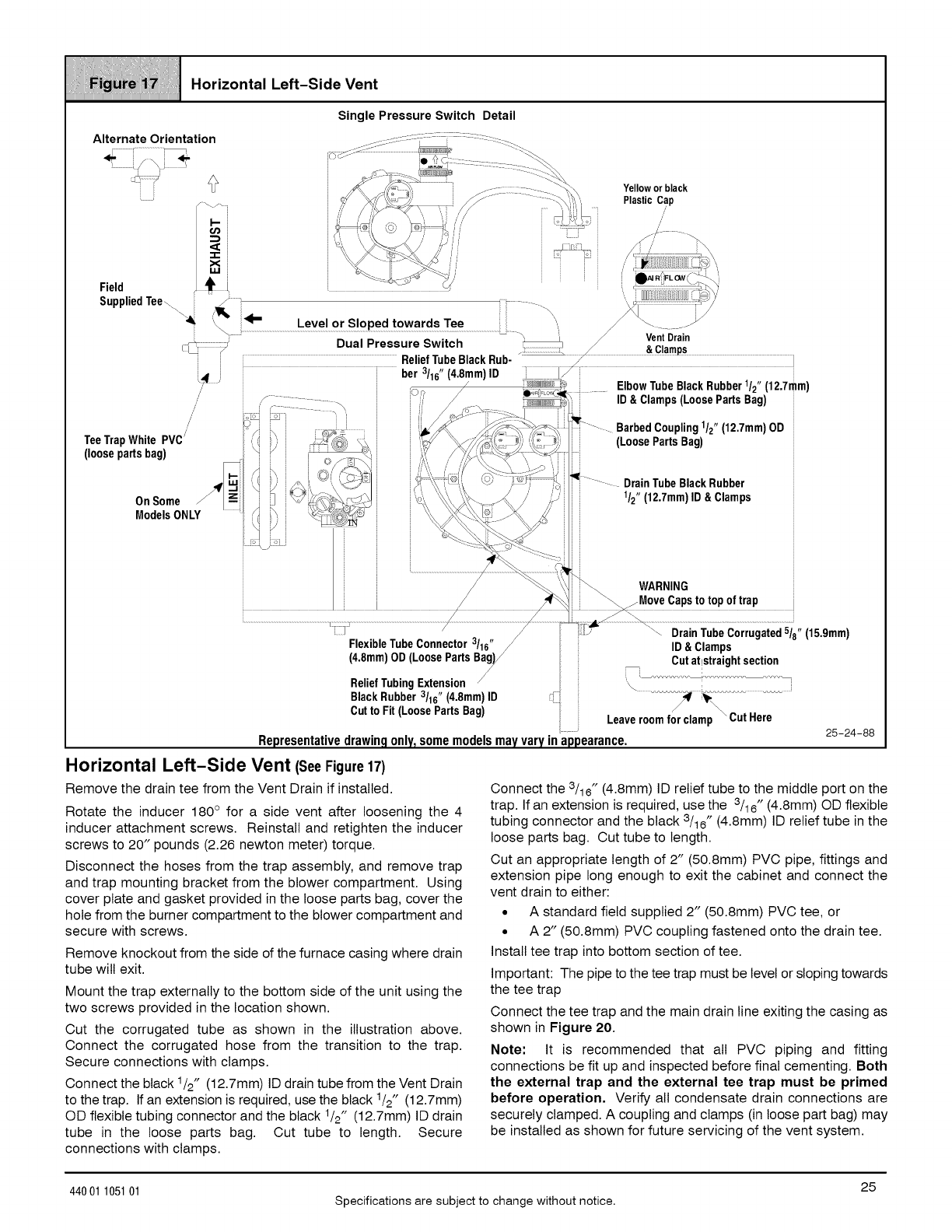
iiiiiiiiiiiiiiiii_;iiiii!ii!_iii1ii!iiii_iii:;i:;iii_iii!iHiiiii_ii1iiiiii_i_iiii!iii;_i!iiiiiiii_iiiiiiii!!i_iii1iiiii_i¸
......! iii"o"zonto,,o vont
Single Pressure Switch Detail
/
FlexibleTubeConnector3/16"
(4.8mm)OD(LoosePartsBag/)/j
/
ReliefTubingExtension/
BlackRubber3/16" (4,8mm)ID
Cutto Fit(LoosePartsBag)
ID&Clamps
Cutatlstraightsection
Leaveroomfor clamp _Cut Here
Representativedrawingonly,somemodelsmayvaryinappearance. 25-24-88
Horizontal Left-Side Vent (SeeFigure17)
Remove the drain tee from the Vent Drain if installed.
Rotate the inducer 180 ° for a side vent after loosening the 4
inducer attachment screws. Reinstall and retighten the inducer
screws to 20" pounds (2.26 newton meter) torque.
Disconnect the hoses from the trap assembly, and remove trap
and trap mounting bracket from the blower compartment. Using
cover plate and gasket provided in the loose parts bag, cover the
hole from the burner compartment to the blower compartment and
secure with screws.
Remove knockout from the side of the furnace casing where drain
tube will exit.
Mount the trap externally to the bottom side of the unit using the
two screws provided in the location shown.
Cut the corrugated tube as shown in the illustration above.
Connect the corrugated hose from the transition to the trap.
Secure connections with clamps.
Connect the black 1/2" (12.7mm) ID drain tube from the Vent Drain
to the trap. If an extension is required, use the black 1/2" (12.7mm)
OD flexible tubing connector and the black 1/2" (12.7mm) ID drain
tube in the loose parts bag. Cut tube to length. Secure
connections with clamps.
Connect the 3/16" (4.8mm) ID relief tube to the middle port on the
trap. If an extension is required, use the 3/16" (4.8mm) OD flexible
tubing connector and the black 3/16" (4.8mm) ID relief tube in the
loose parts bag. Cut tube to length.
Cut an appropriate length of 2" (50.8mm) PVC pipe, fittings and
extension pipe long enough to exit the cabinet and connect the
vent drain to either:
• A standard field supplied 2" (50.8mm) PVC tee, or
• A 2" (50.8mm) PVC coupling fastened onto the drain tee.
Install tee trap into bottom section of tee.
Important: The pipe to the tee trap must be level or sloping towards
the tee trap
Connect the tee trap and the main drain line exiting the casing as
shown in Figure 20.
Note: It is recommended that all PVC piping and fitting
connections be fit up and inspected before final cementing. Both
the external trap and the external tee trap must be primed
before operation, Verify all condensate drain connections are
securely clamped. A coupling and clamps (in loose part bag) may
be installed as shown for future servicing of the vent system.
25
44001 105101 Specifications are subject to change without notice.
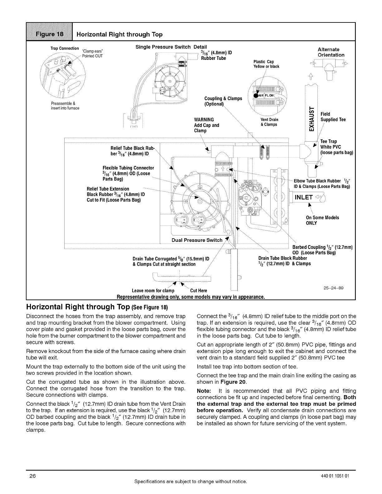
///i/!!!iiii_iiiiiill_iiiiiiiii!!!iiliiiiiiii!iiiii/iii//!!/ii!;l/i//i/i
=or,=..,.,=,ghtthrough
TrapConnection "Clampears"
Preassemble&
insertinto furnace
Single Pressure Switch Detail
_ _ ....................., 3/16" (4,8mm)ID
i',; _ /\ J.................)RubberTube
'"/" ;9_B_,-;,K,Z
///'/" '_ _:+ _. Coupling&Clamps
/_< (Optional)
, AddCapand \,
Clamp _
Plastic Cap
Yellowor black
/,
/
Vent Drain
& Clamps
Alternate
Orientation
_i Field
iSuppliedTee
,///
Leaveroomforclamp "CutHere
Representativedrawingonly,somemodelsmayvaryinappearance.
Horizontal Right through Top (SeeFigure18)
Disconnect the hoses from the trap assembly, and remove trap
and trap mounting bracket from the blower compartment. Using
cover plate and gasket provided in the loose parts bag, cover the
hole from the burner compartment to the blower compartment and
secure with screws.
Remove knockout from the side of the furnace casing where drain
tube will exit.
Mount the trap externally to the bottom side of the unit using the
two screws provided in the location shown.
Cut the corrugated tube as shown in the illustration above.
Connect the corrugated hose from the transition to the trap.
Secure connections with clamps.
Connect the black 1/2" (12.7mm) ID drain tube from the Vent Drain
to the trap. If an extension is required, use the black 1/2" (12.7mm)
OD barbed coupling and the black 1/2" (12.7mm) ID drain tube in
the loose parts bag. Cut tube to length. Secure connections with
clamps.
25-24-89
Connect the 3/16" (4.8mm) ID relief tube to the middle port on the
trap. If an extension is required, use the clear 3/16" (4.8mm) OD
flexible tubing connector and the black 3/16" (4.8mm) ID relief tube
in the loose parts bag. Cut tube to length.
Cut an appropriate length of 2" (50.8mm) PVC pipe, fittings and
extension pipe long enough to exit the cabinet and connect the
vent drain to a standard field supplied 2" (50.8mm) PVC tee
Install tee trap into bottom section of tee.
Connect the tee trap and the main drain line exiting the casing as
shown in Figure 20.
Note: It is recommended that all PVC piping and fitting
connections be fit up and inspected before final cementing. Both
the external trap and the external tee trap must be primed
before operation, Verify all condensate drain connections are
securely clamped. A coupling and clamps (in loose part bag) may
be installed as shown for future servicing of the vent system.
26
Specifications are subject to change without notice.
440 01 105101
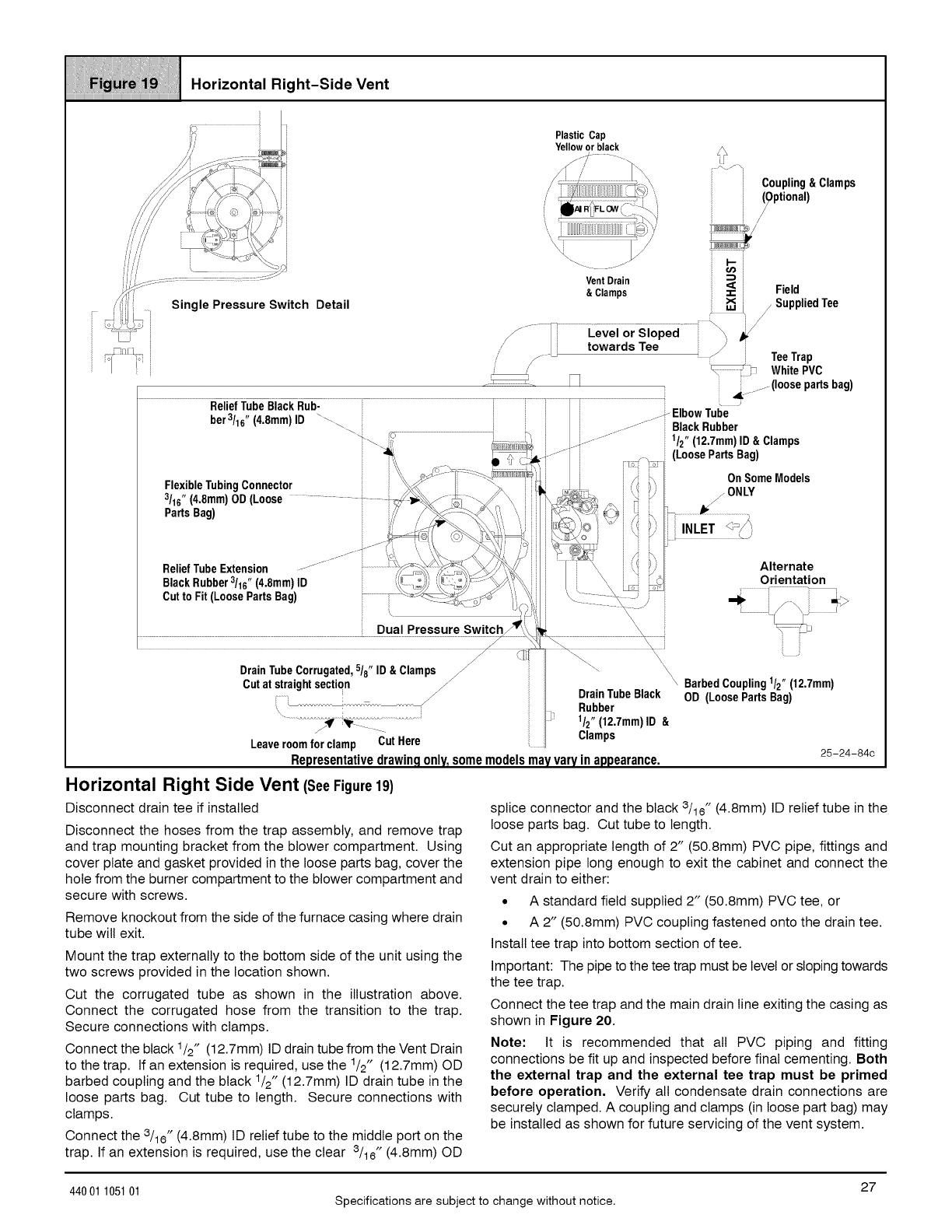
iiiiiiiiiiiiiiiii_;iiiY!i1ii!!!i_ii!!iiiii_;iii!_iiii_iiiiiiiiiiiii_ii!ii_i_ii`_11!i!iiii11iiiii_ii!_ii11ii!iiii!!_i1iii!_i_
! .o.zon.°,.,...-S,°ovont
Plastic Cap
Yellow or black
Coupling&Clamps
Optional)
//
Detail
Vent Drain
& Clamps Field
25-24-84c
Horizontal Right Side Vent (SeeFigure19)
Disconnect drain tee if installed
Disconnect the hoses from the trap assembly, and remove trap
and trap mounting bracket from the blower compartment. Using
cover plate and gasket provided in the loose parts bag, cover the
hole from the burner compartment to the blower compartment and
secure with screws.
Remove knockout from the side of the furnace casing where drain
tube will exit.
Mount the trap externally to the bottom side of the unit using the
two screws provided in the location shown.
Cut the corrugated tube as shown in the illustration above.
Connect the corrugated hose from the transition to the trap.
Secure connections with clamps.
Connect the black 1/2" (12.7mm) ID drain tube from the Vent Drain
to the trap. If an extension is required, use the 1/2" (12.7mm) OD
barbed coupling and the black 1/2" (12.7mm) ID drain tube in the
loose parts bag. Cut tube to length. Secure connections with
clamps.
Connect the 3/16" (4.8mm) ID relief tube to the middle port on the
trap. If an extension is required, use the clear 3/16" (4.8mm) OD
splice connector and the black 3/16" (4.8mm) ID relief tube in the
loose parts bag. Cut tube to length.
Cut an appropriate length of 2" (50.8mm) PVC pipe, fittings and
extension pipe long enough to exit the cabinet and connect the
vent drain to either:
• A standard field supplied 2" (50.8mm) PVC tee, or
• A 2" (50.8mm) PVC coupling fastened onto the drain tee.
Install tee trap into bottom section of tee.
Important: The pipe to the tee trap must be level or sloping towards
the tee trap.
Connect the tee trap and the main drain line exiting the casing as
shown in Figure 20.
Note: It is recommended that all PVC piping and fitting
connections be fit up and inspected before final cementing. Both
the external trap and the external tee trap must be primed
before operation. Verify all condensate drain connections are
securely clamped. A coupling and clamps (in loose part bag) may
be installed as shown for future servicing of the vent system.
27
44001 105101 Specifications are subject to change without notice.
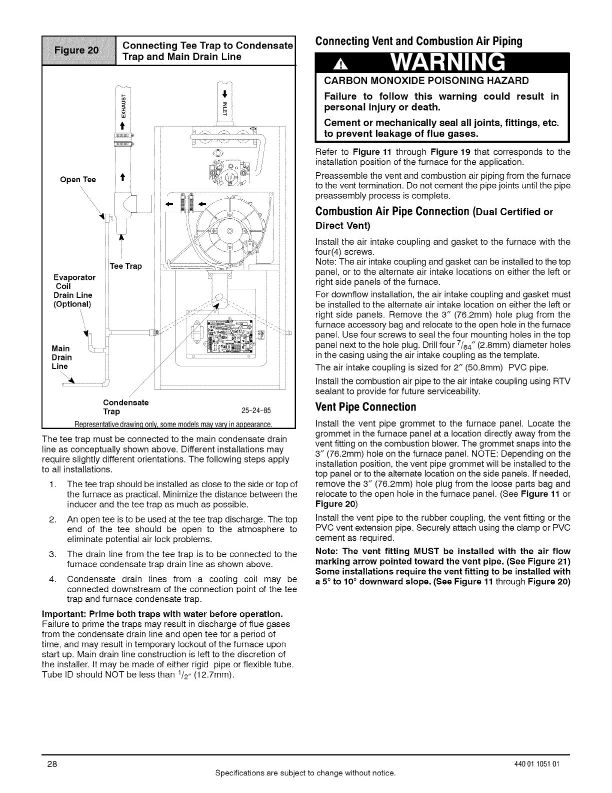
iiiiiii_iiiiii;ii/iii;iiii_iiiiiiiiii_;_;_;iiiiii;Ui_i¸I¸iii_iiiii_?i!Jiiiiiii_iiiii/iiii;iiii/iiiiiii};iiii;ii!iiiiiiiiiiiiiiiiiiiiii¸I¸
Connecting Tee Trap to Condensate
.........................................................................................................................................................Trap and Main Drain Line
The tee trap must be connected to the main condensate drain
line as conceptually shown above. Different installations may
require slightly different orientations. The following steps apply
to all installations.
1. The tee trap should be installed as close to the side or top of
the furnace as practical. Minimize the distance between the
inducer and the tee trap as much as possible.
2. An open tee is to be used at the tee trap discharge. The top
end of the tee should be open to the atmosphere to
eliminate potential air lock problems.
3. The drain line from the tee trap is to be connected to the
furnace condensate trap drain line as shown above.
4. Condensate drain lines from a cooling coil may be
connected downstream of the connection point of the tee
trap and furnace condensate trap.
Important: Prime both traps with water before operation.
Failure to prime the traps may result in discharge of flue gases
from the condensate drain line and open tee for a period of
time, and may result in temporary lockout of the furnace upon
start up. Main drain line construction is left to the discretion of
the installer. It may be made of either rigid pipe or flexible tube.
Tube ID should NOT be less than 1/2, (12.7mm).
Connecting Vent and Combustion Air Piping
CARBON MONOXIDE POISONING HAZARD
Failure to follow this warning could result in
personal injury or death.
Cement or mechanically seal all joints, fittings, etc.
to prevent leakage of flue gases.
Refer to Figure 11 through Figure 19 that corresponds to the
installation position of the furnace for the application.
Preassemble the vent and combustion air piping from the furnace
to the vent termination. Do not cement the pipe joints until the pipe
preassembly process is complete.
Combustion Air Pipe Connection (Dual Certified or
Direct Vent)
Install the air intake coupling and gasket to the furnace with the
four(4) screws.
Note: The air intake coupling and gasket can be installed to the top
panel, or to the alternate air intake locations on either the left or
right side panels of the furnace.
For downflow installation, the air intake coupling and gasket must
be installed to the alternate air intake location on either the left or
right side panels. Remove the 3" (76.2mm) hole plug from the
furnace accessory bag and relocate to the open hole in the furnace
panel. Use four screws to seal the four mounting holes in the top
panel next to the hole plug. Drill four 7/64" (2.8mm) diameter holes
in the casing using the air intake coupling as the template.
The air intake coupling is sized for 2" (50.8mm) PVC pipe.
Install the combustion air pipe to the air intake coupling using RTV
sealant to provide for future serviceability.
Vent Pipe Connection
Install the vent pipe grommet to the furnace panel. Locate the
grommet in the furnace panel at a location directly away from the
vent fitting on the combustion blower. The grommet snaps into the
3" (76.2mm) hole on the furnace panel. NOTE: Depending on the
installation position, the vent pipe grommet will be installed to the
top panel or to the alternate location on the side panels. If needed,
remove the 3" (76.2mm) hole plug from the loose parts bag and
relocate to the open hole in the furnace panel. (See Figure 11 or
Figure 20)
Install the vent pipe to the rubber coupling, the vent fitting or the
PVC vent extension pipe. Securely attach using the clamp or PVC
cement as required.
Note: The vent fitting MUST be installed with the air flow
marking arrow pointed toward the vent pipe, (See Figure 21)
Some installations require the vent fitting to be installed with
a 5° to 10° downward slope, (See Figure 11 through Figure 20)
28
Specifications are subject to change without notice.
440 01 105101
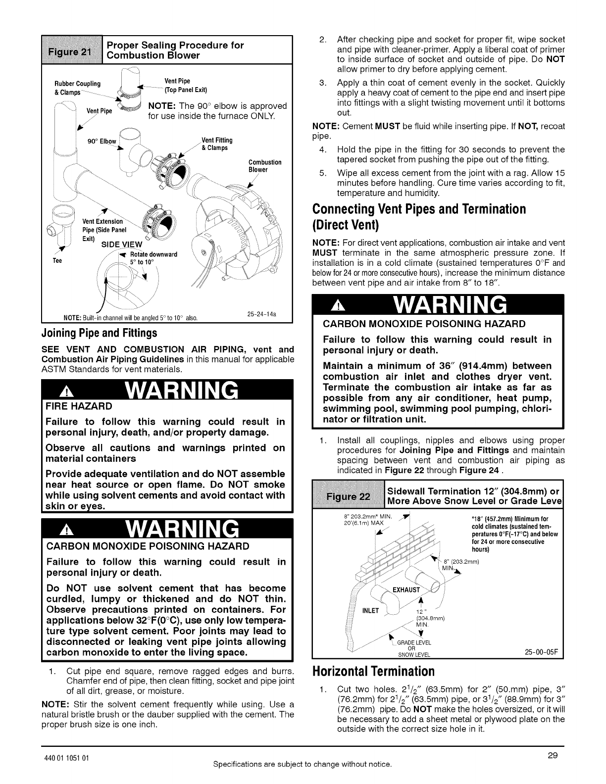
///iiiillliliiiiiiii!/i!iii{iiil@iii!!i;iii/i!,i@Xiiii/lliiii'
Proper Sealing Procedure for
Combustion Blower
RubberCoupling J _ Vent Pipe
&Clamps- _T (Top Panel Exit)
/_'_ VentPi.e _j NOTE: The 90 ° elbow is approved
/P=.-
ii_l_ for use inside the furnace ONLY.
25-24-14a
NOTE:Built-in channelwill be angled5°to 10° also.
Joining Pipe and Fittings
SEE VENT AND COMBUSTION AIR PIPING, vent and
Combustion Air Piping Guidelines in this manual for applicable
ASTM Standards for vent materials.
FIRE HAZARD
Failure to follow this warning could result in
personal injury, death, and/or property damage.
Observe all cautions and warnings printed on
material containers
Provide adequate ventilation and do NOT assemble
near heat source or open flame. Do NOT smoke
while using solvent cements and avoid contact with
skin or eyes.
CARBON MONOXIDE POISONING HAZARD
Failure to follow this warning could result in
personal injury or death.
Do NOT use solvent cement that has become
curdled, lumpy or thickened and do NOT thin.
Observe precautions printed on containers. For
applications below 32°F(0°C), use only low tempera-
ture type solvent cement. Poor joints may lead to
disconnected or leaking vent pipe joints allowing
carbon monoxide to enter the living space.
1. Cut pipe end square, remove ragged edges and burrs.
Chamfer end of pipe, then clean fitting, socket and pipe joint
of all dirt, grease, or moisture.
NOTE: Stir the solvent cement frequently while using. Use a
natural bristle brush or the dauber supplied with the cement. The
proper brush size is one inch.
2. After checking pipe and socket for proper fit, wipe socket
and pipe with cleaner-primer. Apply a liberal coat of primer
to inside surface of socket and outside of pipe. Do NOT
allow primer to dry before applying cement.
3. Apply a thin coat of cement evenly in the socket. Quickly
apply a heavy coat of cement to the pipe end and insert pipe
into fittings with a slight twisting movement until it bottoms
out.
NOTE: Cement MUST be fluid while inserting pipe. If NOT, recoat
pipe.
4. Hold the pipe in the fitting for 30 seconds to prevent the
tapered socket from pushing the pipe out of the fitting.
5. Wipe all excess cement from the joint with a rag. Allow 15
minutes before handling. Cure time varies according to fit,
temperature and humidity.
ConnectingVent Pipes andTermination
(DirectVent)
NOTE: For direct vent applications, combustion air intake and vent
MUST terminate in the same atmospheric pressure zone. If
installation is in a cold climate (sustained temperatures 0°F and
belowfor 24ormoreconsecutivehours), increase the minimum distance
between vent pipe and air intake from 8" to 18".
CARBON MONOXIDE POISONING HAZARD
Failure to follow this warning could result in
personal injury or death.
Maintain a minimum of 36" (914.4mm) between
combustion air inlet and clothes dryer vent.
Terminate the combustion air intake as far as
possible from any air conditioner, heat pump,
swimming pool, swimming pool pumping, chlori-
nator or filtration unit.
1. Install all couplings, nipples and elbows using proper
procedures for Joining Pipe and Fittings and maintain
spacing between vent and combustion air piping as
indicated in Figure 22 through Figure 24.
:Sidewall Termination 12" (304.8mm)or
!iilii lli iii i/i
...................................................................................................................................More Above Snow Level or Grade Leve
iiiiiiiiiiiiiiiiiiiiiiiiiiiiiiiiiiiiiiiiiiiiiiiiiiiiiiiiiiiiiiiiiiiiiiii
8" 203.2mm* MIN. _ "18 =(457.2mm) Minimum for
20'(6 lm) MAX z
' _ i z-_-_, cold climates(sustainedtem-
f_J_ peratures0°F(-17°C) and below
ii _'._ f0r 24 0r moreconsecutive
__f hours)
//_ ,/_ EXHAUST_ ,_ )
f:::i INLET _ / 12"
(304.8mm)
/J" MIN.
._ ', GRADE LEVEL
OR
SNOW LEVEL 25-00-05F
HorizontalTermination
1. Cut two holes. 21/2" (63.5mm) for 2" (50.mm) pipe, 3"
(76.2mm) for 21/2" (63.5mm) pipe, or 31/2 " (88.9mm) for 3"
(76.2mm) pipe. Do NOT make the holes oversized, or it will
be necessary to add a sheet metal or plywood plate on the
outside with the correct size hole in it.
29
44001 105101 Specifications are subject to change without notice.
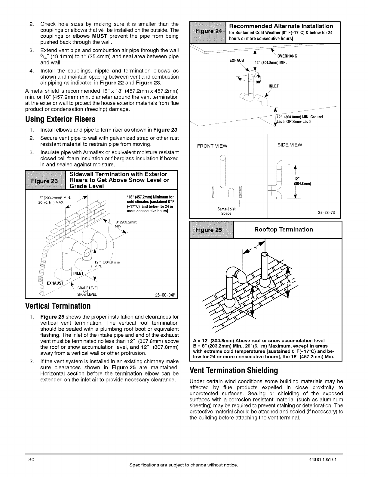
2. Check hole sizes by making sure it is smaller than the
couplings or elbows that wilt be installed on the outside. The
couplings or elbows MUST prevent the pipe from being
pushed back through the wall.
3. Extend vent pipe and combustion air pipe through the wall
3/4" (19.1 mm) to 1" (25.4mm) and seat area between pipe
and wall.
4. Install the couplings, nipple and termination elbows as
shown and maintain spacing between vent and combustion
air piping as indicated in Figure 22 and Figure 23.
A metal shield is recommended 18" x 18" (457.2mm x 457.2mm)
min. or 18" (457.2mm) min. diameter around the vent termination
at the exterior walt to protect the house exterior materials from flue
product or condensation (freezing) damage.
Using ExteriorRisers
1. Install elbows and pipe to form riser as shown in Figure 23.
2. Secure vent pipe to wall with galvanized strap or other rust
resistant material to restrain pipe from moving.
3. Insulate pipe with Armaflex or equivalent moisture resistant
closed cell foam insulation or fiberglass insulation if boxed
in and sealed against moisture.
¢,,'""''-S,oewa,,toZerm,no,,onw,thE.er,Oror
Risers Get Above Snow Level
Grade Level
8" (203.2mm)* MIN. _ "18" (457.2mm) Minimum for
20' (6.1 m) MAX z/ ijz'/-_. _" _ cold climates [sustained0oF
_ll .._/_. (-17°C) and below for 24 or
!f_ - more consecutivehours]
i::::: i 12" 304.8mm
'::::f \ j MIN.
i:::::::Y/ h\__-_= \-. /_
i::::i ,/ INLET3J/
_i::[, EXHAUST//_
// ", GRADE LEVEL
/;:) j_ " OR
--_' /SNOW LEVEL 25-00-04F
VerticalTermination
1. Figure 25 shows the proper installation and clearances for
vertical vent termination. The vertical roof termination
should be sealed with a plumbing roof boot or equivalent
flashing. The inlet of the intake pipe and end of the exhaust
vent must be terminated no less than 12" (307.8mm) above
the roof or snow accumulation level, and 12" (307.8mm)
away from a vertical wall or other protrusion.
2. If the vent system is installed in an existing chimney make
sure clearances shown in Figure25 are maintained.
Horizontal section before the termination elbow can be
extended on the inlet air to provide necessary clearance.
Recommended Alternate Installation
i!_i _i forSustainedColdWeather[0°F(-17°0)& belowfor24
hoursormoreconsecutivehours]
............ '_ _OVERHANG
EXHAUST
_j_V ;2 " (304"8mm)MIN"
LET
A
.......c ..........-i2" (304.8mm) MIN. Ground
.......... ........ _'--_ JJ.evel_TOR Snow Level
FRONT Vl EW
Same Joist
Space
SIDE VIEW
] .........
= =
= =
12"
(304.8mm)
25-23-73
iii/iiiiii__iiiili!ii;iiiiiii Rooftop_rmination
iiiiiiiiiiiiiiiiiiiiiiiiiiiiiiiiiiiiiiiiiiiiiiiiiiiiiiiiiiiiiiiiiiiiiiiiiiiiiiiiiiiiiiiiiiiiiiiiiiiiiiiiiiiiiiiiiiiiiiiiiiiiiiiiiiiiiiiiiiiiiiii
J
A=12" (304.8mm) Above roof or snow accumulation level
B = 8" (203.2mm) Min., 20' (6.1m) Maximum, except in areas
with extreme cold temperatures [sustained 0°F(-17°C) and be-
low for 24 or more consecutive hours], the 18" (457.2mm) Min.
VentTerminationShielding
Under certain wind conditions some building materials may be
affected by flue products expelled in close proximity to
unprotected surfaces. Sealing or shielding of the exposed
surfaces with a corrosion resistant material (such as aluminum
sheeting) may be required to prevent staining or deterioration. The
protective material should be attached and sealed (if necessary) to
the building before attaching the vent terminal.
3O
Specifications are subject to change without notice.
44001 105101
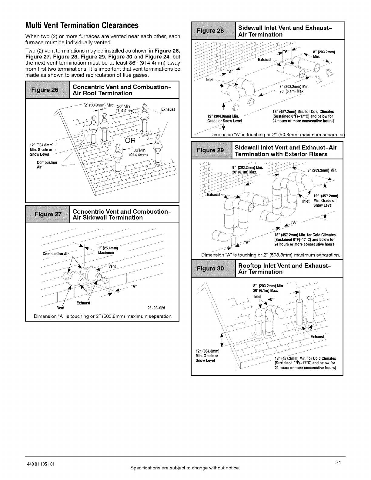
MultiVent TerminationClearances
When two (2) or more furnaces are vented near each other, each
furnace must be individually vented.
Two (2) vent terminations may be installed as shown in Figure 26,
Figure 27, Figure 28, Figure 29, Figure 30 and Figure 24, but
the next vent termination must be at least 36" (914.4mm) away
from first two terminations. It is important that vent terminations be
made as shown to avoid recirculation of flue gases.
; ;: :ii Concentric Vent and Combustion-
, ,_=,_,=v Air Roof Termination
J2" (50.Smm) Max 36" Min
L,_I (_914.4_/_ ............Exhaust
Min. Gradeor , _..... )_ - _ _l_'_J_36"Uin
SnowLevel _- /\'_' _ _._ (914.4mm) Fq
combustion/.... \_ _ -_ __
Ooncen,r,cVan,Oo uot,on-
Air Sidewall Termination
...... iiiiL_......
i jjj
................... _ _.....i" (2_.4mm)............-.....
Combustion Air !...... Maximum .......... .......................
.... J- ....... J/
Vent 25=22-02d
Dimension "A" is touching or 2" (503.8mm) maximum separation.
iiiiiii;_iiiiiii[i_i;_i_i_i_IIi7`i1ii!!i!ii!!iiiii_ii7`_iiiiiiii_[iiiii1iiii_iiii_i_ii!7i_i_i1_iiiiiiiiiiiii_@ii
Sidewall Inlet Vent and Exhaust-
Air Termination
----_.<-; 7-j- .s---'.. J..- -'s>_.J - _ i i/-:-__ _- Min.
Sm--];fj_-_;::_-_j_---:;_-->:j> ..... Exhaust. i__J ,/_ _ --,ll
-" --" _w .J A"' -J \ t _---vJ _\\
.- J- J- -- i --- _v. /_$
J jJ i _ %# _ y4,,\
...... Inlet _ i j-i,! _ ...... _ L>_ ....
,(\" _ '.............. 8"(283.2mm) Min, -......
1, , \\ '1 _........ ........ 28' (6,1m)Max,
t. _..> s i ..... _......
k7" ///% ..........
12" (384.8mm)M/i_. .... -" _ 18;_57ne2g_-i17f_; aCSd_eCllo_afters
Gradeor Snow Level 24 hours or more consecutivehours]
iii Sidewall Inlet Vent and Exhaust-Air
Termination with Exterior Risers
J_- __ f-- 28' (6.1m)Max. _;_: ..... _7\ !izua,zmmjlvlin.
>--[_j __- ,--<_ .>-- .+_ _.... :_-,iv /, p.-
/-/-W" !%__ ,(_---_---i C JInlet Min.Gradeor
,' . _ y_v%_J _ _)-. " Snow Level
i :_L.) '-L J, --_
18" (457.2mm) Min. for Cold Climates
[Sustained 8°F(-17°0) andbelow for
24 hours or more consecutivehours]
Dimension "A" is touching or 2" (503.8mm) maximum separation.
ii:
Rooftop Inlet Vent and Exhaust-
Air Termination
',, 8" (283.2mm)Min, "..... ",_fm ---_-....
_",, ",, 28' (6.1m) Max. ,_. ' , ...... ',,
\,,"',, ----"_-U'- _,_,_l4- _-:,----_ --<,---_....
"',,"',,.....->........- _--7;_V_ZL--,<-i-'_7--s......
""".... _ "_,"_-_',7"_ i7-__......"....
, , {_--, ..J-F -_---*_7.A\t,,{7/ -',
,, .... _J _ .,._.-t, ->Jt_;" \, _.%-J
,_- it, F=_',, .--- ,__
__.--->,i'\,-;_;_7_777::::::::::-_,,,":_777;"_----,_J'--777.........:'---;777:-
Min, Gradeor ',, ,_J>-J', _".......... -......
Snow Level ", \, .... ;......... .-- 18" (457.2mm)Min.for ColdClimates
_\"1-- ............. [Sustained 8°F(-17°0) and below for
;;-4_........... 24 hoursor moreconsecutivehours]
31
44001 105101 Specifications are subject to change without notice.
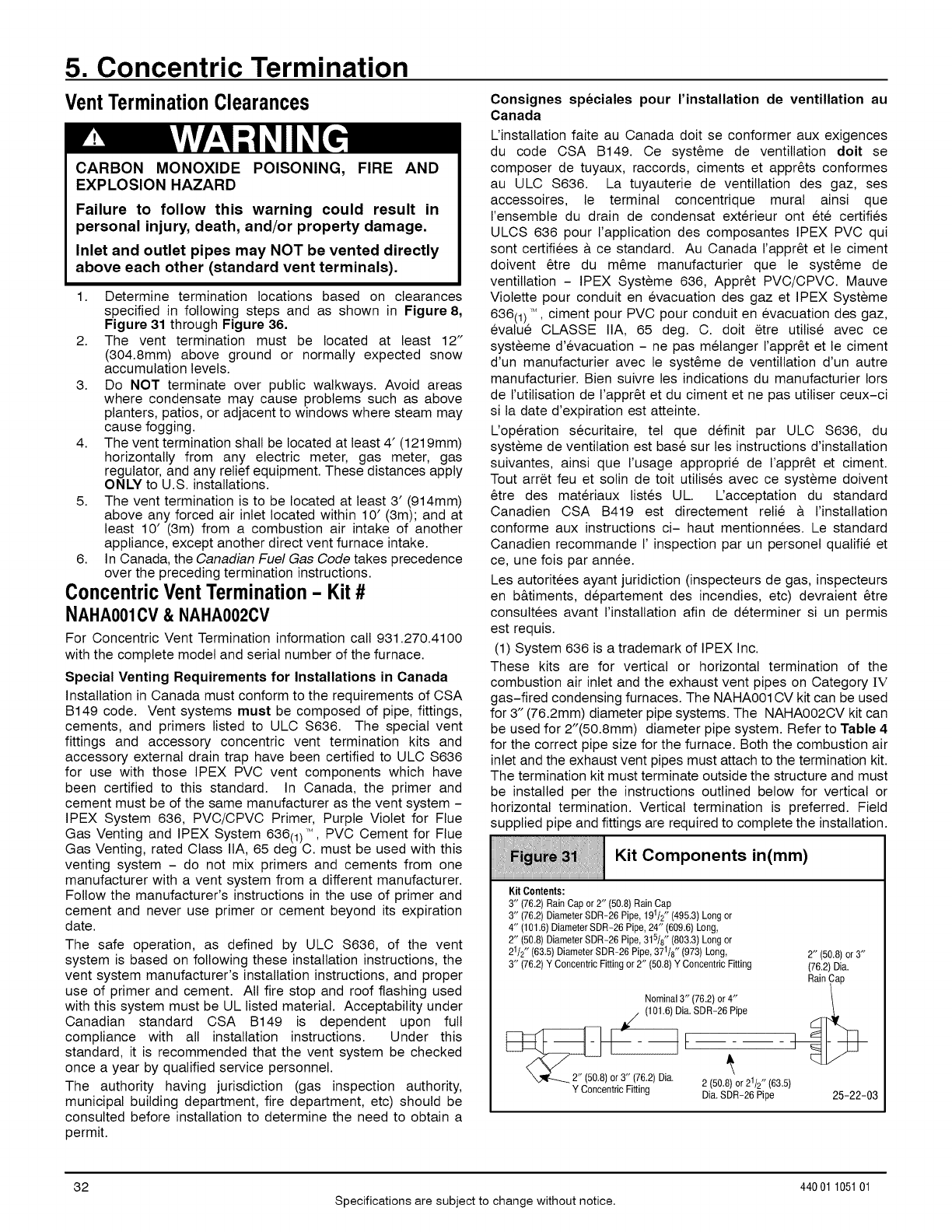
5. Concentric Termination
Vent TerminationClearances
CARBON MONOXIDE POISONING, FIRE AND
EXPLOSION HAZARD
Failure to follow this warning could result in
personal injury, death, and/or property damage.
Inlet and outlet pipes may NOT be vented directly
above each other (standard vent terminals).
1. Determine termination locations based on clearances
specified in following steps and as shown in Figure 8,
Figure 31 through Figure 36.
2. The vent termination must be located at least 12"
(304.8mm) above ground or normally expected snow
accumulation levels.
3. Do NOT terminate over public walkways. Avoid areas
where condensate may cause problems such as above
planters, patios, or adjacent to windows where steam may
cause fogging.
4. The vent termination shall be located at least 4' (1219mm)
horizontally from any electric meter, gas meter, gas
regulator, and any relief equipment. These distances apply
ONLY to U.S. installations.
5. The vent termination is to be located at least 3' (914mm)
above any forced air inlet located within 10' (3m); and at
least 10' (3m) from a combustion air intake of another
appliance, except another direct vent furnace intake.
6. In Canada, the Canadian Fuel Gas Code takes precedence
over the preceding termination instructions.
ConcentricVentTermination-Kit #
NAHA001CV & NAHA002CV
For Concentric Vent Termination information call 931.270.4100
with the complete model and serial number of the furnace.
Special Venting Requirements for Installations in Canada
Installation in Canada must conform to the requirements of CSA
B149 code. Vent systems must be composed of pipe, fittings,
cements, and primers listed to ULC S636. The special vent
fittings and accessory concentric vent termination kits and
accessory external drain trap have been certified to ULC S636
for use with those IPEX PVC vent components which have
been certified to this standard. In Canada, the primer and
cement must be of the same manufacturer as the vent system -
IPEX System 636, PVC/CPVC Primer, Purple Violet for Flue
Gas Venting and IPEX System 636(1)'M, PVC Cement for Flue
Gas Venting, rated Class IIA, 65 deg C. must be used with this
venting system - do not mix primers and cements from one
manufacturer with a vent system from a different manufacturer.
Follow the manufacturer's instructions in the use of primer and
cement and never use primer or cement beyond its expiration
date.
The safe operation, as defined by ULC S636, of the vent
system is based on following these installation instructions, the
vent system manufacturer's installation instructions, and proper
use of primer and cement. All fire stop and roof flashing used
with this system must be UL listed material. Acceptability under
Canadian standard CSA B149 is dependent upon full
compliance with all installation instructions. Under this
standard, it is recommended that the vent system be checked
once a year by qualified service personnel.
The authority having jurisdiction (gas inspection authority,
municipal building department, fire department, etc) should be
consulted before installation to determine the need to obtain a
permit.
Consignes sp6ciales pour I'installation de ventillation au
Canada
L'installation faite au Canada dolt se conformer aux exigences
du code CSA B149. Ce syst_me de ventillation doit se
composer de tuyaux, raccords, ciments et appr_ts conformes
au ULC S636. La tuyauterie de ventillation des gaz, ses
accessoires, le terminal concentrique mural ainsi que
I'ensembte du drain de condensat exterieur ont et6 certifies
ULCS 636 pour I'application des composantes IPEX PVC qui
sont certifiees & ce standard. Au Canada I'appr_t et le ciment
doivent _tre du m_me manufacturier que le syst_me de
ventillation - IPEX Systeme 636, Appr_t PVC/CPVC. Mauve
Violette pour conduit en evacuation des gaz et IPEX Systeme
636(1) ,M,ciment pour PVC pour conduit en evacuation des gaz,
evalue CLASSE IIA, 65 deg. C. dolt etre utilise avec ce
systeeme d'evacuation - ne pas melanger I'appr_t et le ciment
d'un manufacturier avec le syst_me de ventillation d'un autre
manufacturier. Bien suivre les indications du manufacturier Iors
de I'utilisation de I'appr_t et du ciment et ne pas utiliser ceux-ci
si la date d'expiration est atteinte.
Uoperation securitaire, tel que definit par ULC S636, du
systeme de ventilation est base sur les instructions d'installation
suivantes, ainsi que I'usage approprie de I'appr_t et ciment.
Tout arret feu et solin de toit utilises avec ce systeme doivent
_tre des materiaux listes UL. Uacceptation du standard
Canadien CSA B419 est directement retie a I'installation
conforme aux instructions ci- haut mentionnees. Le standard
Canadien recommande I' inspection par un personel qualifie et
ce, une fois par annee.
Les autoritees ayant juridiction (inspecteurs de gas, inspecteurs
en b&timents, departement des incendies, etc) devraient _tre
consultees avant I'installation afin de determiner si un permis
est requis.
(1) System 636 is a trademark of IPEX Inc.
These kits are for vertical or horizontal termination of the
combustion air inlet and the exhaust vent pipes on Category IV
gas-fired condensing furnaces. The NAHAO01CV kit can be used
for 3" (76.2mm) diameter pipe systems. The NAHAOO2CV kit can
be used for 2"(50.8mm) diameter pipe system. Refer to Table 4
for the correct pipe size for the furnace. Both the combustion air
inlet and the exhaust vent pipes must attach to the termination kit.
The termination kit must terminate outside the structure and must
be installed per the instructions outlined below for vertical or
horizontal termination. Vertical termination is preferred. Field
supplied pipe and fittings are required to complete the installation.
co o.o.,s
iiiiiiiiiiiiiiiiiiiiiiiiiiiiiiiiiiiiiiiiiiiiiiiiiiiiiiiiiiiiiiiiiiiiiiiiiiiiiiiiiiiiiiiiiiiiiiiiiiiiiiiiiiiiiiiiiiiiiiiiiiiiiiiiiiiiiiiiiiiiiiii
Kit Contents:
3" (76.2)RainCap or 2" 50.8 Rain Cap
3" (76.2)DiameterSDR-26 Pipe, 191/2"(495.3) Longor
4" (101.6)DiameterSDR-26 Pipe, 24" (609.6)Long,
2" (50.8)DiameterSDR-26 Pipe, 315/8"(803.3) Longor
21/2" (63.5) DiameterSDR-26 Pipe,371/8" (973) Long,
3" (76.2)Y ConcentricFittingor 2" (50.8)Y Concentric Fitting 2" (50.8)or 3"
(76.2) Dia.
RainCap
Nominal 3" (76.2) or 4"
/(101.6) Dia.SDR-26 Pipe
_2"(50.8)0r3"(6 ) 1 35
" " "2 (50.8) or 2 /2" (6 .)
Y ConcentricFitting Dia. SDR-26 Pipe 25-22-03
32
Specifications are subject to change without notice.
440 01 105101
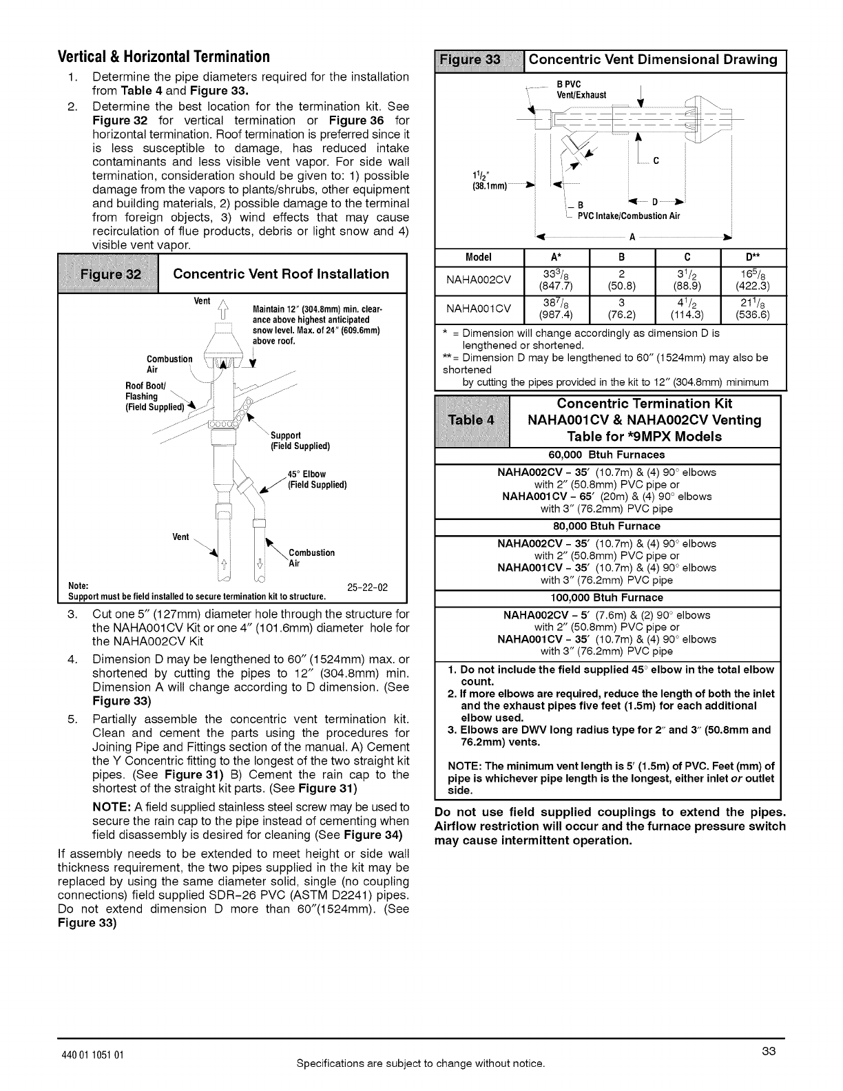
Vertical & HorizontalTermination
1.
2.
Determine the pipe diameters required for the installation
from Table 4 and Figure 33.
Determine the best location for the termination kit. See
Figure32 for vertical termination or Figure36 for
horizontal termination. Roof termination is preferred since it
is less susceptible to damage, has reduced intake
contaminants and less visible vent vapor. For side wall
termination, consideration should be given to: 1) possible
damage from the vapors to plants/shrubs, other equipment
and building materials, 2) possible damage to the terminal
from foreign objects, 3) wind effects that may cause
recirculation of flue products, debris or light snow and 4)
visible vent vapor.
_i_i_i_i_i_ii!i_J_j_i;ii_Hiiii_i_ii1iIi_iiiiii!!iiiii_!_iii_i_iiii_{i{ii_iiiHiiiii{_}i_!{{!ii]iiii{_{i_}]i]iiiiii}i]{
Concentric Vent Roof Installation
iiiiiiiiiiiiiiiiiiiiiiiiiiiiiiiiiiiiiiiiiiiiiiiiiiiiiiiiiiiiiiiiiiiiiiiiiiiiiiiiiiiiiiiiiiiiiiiiiiiiiiiiiiiiiiiiiiiiiiiiiiiiiiiiiiiiiiiiiiiiiiii
Vent A
_l; Maintain12" (304.8mm)min.clear-
iJ........ ance abovehighestanticipated
J snow level. Max. of 24" (609.6mm)
/\,\
/aboveroof.
Combustion i _i_'_,'; V
Air " IUll _ -
Roof Boot/ I] -_-_::_J" .........
Flashing _.. .:_ bz_,_ jjz
(Field Supplied)_J-!- _F"
:%...... r"0
.............. Support
_:' (Field Supplied)
!_X_ _5iel51b°;plie d)
z_i _Air
Note: 25-22-02
Support mustbe field installedto secure terminationkit to structure.
3. Cut one 5" (127mm) diameter hole through the structure for
the NAHA001CV Kit or one 4" (101.6mm) diameter hole for
the NAHA002CV Kit
4. Dimension D may be lengthened to 60" (1524mm) max. or
shortened by cutting the pipes to 12" (304.8mm) min.
Dimension A will change according to D dimension. (See
Figure 33)
5. Partially assemble the concentric vent termination kit.
Clean and cement the parts using the procedures for
Joining Pipe and Fittings section of the manual. A) Cement
the Y Concentric fitting to the longest of the two straight kit
pipes. (See Figure 31) B) Cement the rain cap to the
shortest of the straight kit parts. (See Figure 31)
NOTE: A field supplied stainless steel screw may be used to
secure the rain cap to the pipe instead of cementing when
field disassembly is desired for cleaning (See Figure 34)
If assembly needs to be extended to meet height or side wall
thickness requirement, the two pipes supplied in the kit may be
replaced by using the same diameter solid, single (no coupling
connections) field supplied SDR-26 PVC (ASTM D2241) pipes.
Do not extend dimension D more than 60"(1524mm). (See
Figure 33)
Fi_3_ !/Concentric Vent Dimensional Drawing
iiiiiiiiiiiiiiiiii_iiiiiiiiiiiii]iiii]iiii]iiii]iiii]iiii]iiii]iiiii]iiiii]iiiii]iiiii]iiiii]iiiii]ii}ii}
...... B PVC
A lw
Model A* B C D**
NAHA002CV 333/8 2 31/2 165/8
(847.7) (50.8) (88.9) (422.3)
NAHA001CV 387/8 3 41/2 211/8
(987.4) (76.2) (114.3) (536.6)
* = Dimension will change accordingly as dimension D is
lengthened or shortened.
** = Dimension Dmay be lengthened to 60" (1524mm) may also be
shortened
by cuttingthe pipes providedin the kitto 12" (304.8mm)minimum
Concentric Termination Kit
_ NAHA001OV &NAHA002OV Venting
Table for *gMPX Models
60,000BtuhFurnaces
NAHAOO2CV-35' (10.7m) & (4) 90° elbows
with 2" (50.8mm) PVC pipe or
NAHAOOIOV- 65' (20m) & (4) 90° elbows
with 3" (76.2mm) PVC pipe
80,000 Btuh Furnace
NAHAOO2OV- 35' (10.7m) & (4) 90° elbows
with 2" (50.8mm) PVC pipe or
NAHAOOIOV- 35' (10.7m) & (4) 90° elbows
with 3" (76.2mm) PVC pipe
100,000Btuh Furnace
NAHAOO2OV- 5' (7.6m) & (2) 90 ° elbows
with 2" (50.8mm) PVC pipe or
NAHAOOIOV- 35' (10.7m) & (4) 90° elbows
with 3" (76.2mm) PVC pipe
1. Do not include the field supplied 45 °elbow in the total elbow
count.
2, If more elbows are required, reduce the length of both the inlet
and the exhaust pipes five feet (1,5m) for each additional
elbow used.
3, Elbows are DWV long radius type for 2" and 3" (50.8mm and
76.2mm) vents.
NOTE: The minimum vent length is 5' (1.5m) of PVC. Feet (mm) of
pipe is whichever pipe length is the longest, either inlet or outlet
side.
Do not use field supplied couplings to extend the pipes.
Airflow restriction will occur and the furnace pressure switch
may cause intermittent operation.
33
44001 105101 Specifications are subject to change without notice.
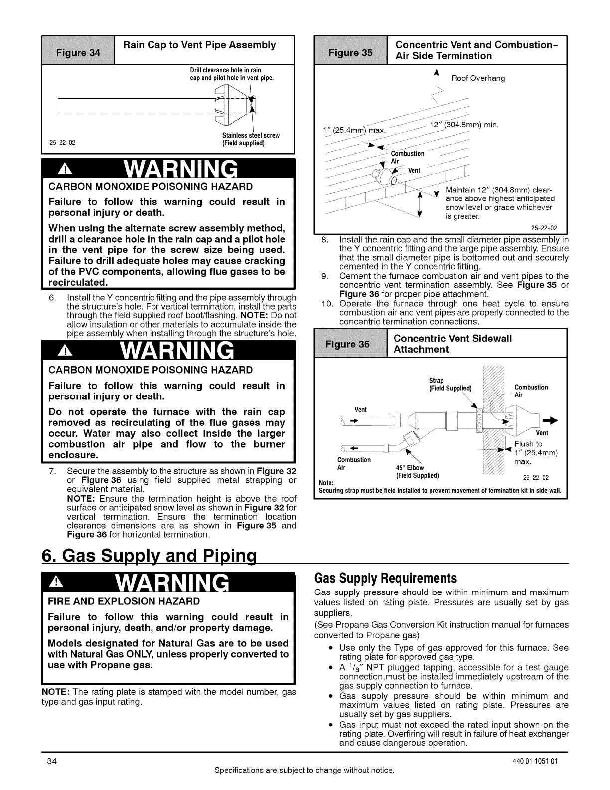
///i///Iiil//iiiili11111,ii//iiiltiiiiiiiiii/i!//iliili//!!ii/itill!
L ' =o,ntovent ooe==
25-22-02
Drill clearance hole in rain
cap and pilothole invent pipe.
elscrew
(Field supplied)
CARBON MONOXIDE POISONING HAZARD
Failure to follow this warning could result in
personal injury or death.
When using the alternate screw assembly method,
drill a clearance hole in the rain cap and a pilot hole
in the vent pipe for the screw size being used.
Failure to drill adequate holes may cause cracking
of the PVC components, allowing flue gases to be
recirculated.
6. Install the Y concentric fitting and the pipe assembly through
the structure's hole. For vertical termination, install the parts
through the field supplied roof boot/flashing. NOTE: Do not
allow insulation or other materials to accumulate inside the
pipe assembly when installing through the structure's hole.
CARBON MONOXIDE POISONING HAZARD
Failure to follow this warning could result in
personal injury or death.
Do not operate the furnace with the rain cap
removed as recirculating of the flue gases may
occur. Water may also collect inside the larger
combustion air pipe and flow to the burner
enclosure.
7. Secure the assembly to the structure as shown in Figure 32
or Figure36 using field supplied metal strapping or
equivalent material.
NOTE: Ensure the termination height is above the roof
surface or anticipated snow level as shown in Figure 32 for
vertical termination. Ensure the termination location
clearance dimensions are as shown in Figure 35 and
Figure 36 for horizontal termination.
6. Gas Supply and Piping
FIRE AND EXPLOSION HAZARD
Failure to follow this warning could result in
personal injury, death, and/or property damage.
Models designated for Natural Gas are to be used
with Natural Gas ONLY, unless properly converted to
use with Propane gas.
NOTE: The rating plate is stamped with the model number, gas
type and gas input rating.
i//ii///Iiil//iiiili11111,ii//iiiltiiiiiiiiii/i!/!!lii/!li!iiliiii/iii
Concentric Vent and Combustion-
Air Side Termination
t Roof Overhang
r,i ax. -/ /z ) " "
......._..................___J:- Combustion .......... _....
........................_44- - .... ..............
....... ............ 4,_J-/_ Vent " ._- .....
_.----Jj---'L_/:/.__._j_.__.j-_Z\t-!2__';L: ...... JMaintam----_-12 304 8mm clear
-_-_------....... ___._-- ............ _''_' ance above hlghest antlcipated
........................... i snow level or grade whichever
...........Yis greater.
25-22-02
8. Install the rain cap and the small diameter pipe assembly in
the Y concentric fitting and the large pipe assembly. Ensure
that the small diameter pipe is bottomed out and securely
cemented in the Y concentric fitting.
9. Cement the furnace combustion air and vent pipes to the
concentric vent termination assembly. See Figure 35 or
Figure 36 for proper pipe attachment.
10. Operate the furnace through one heat cycle to ensure
combustion air and vent pipes are properly connected to the
concentric termination connections.
Concentric Vent Sidewall
Attachment
Air
(Field Supplied) 25-22-02
Note:
Securingstrapmust be field installed to preventmovementof terminationkitin sidewall.
Gas Supply Requirements
Gas supply pressure should be within minimum and maximum
values listed on rating plate. Pressures are usually set by gas
suppliers.
(See Propane Gas Conversion Kit instruction manual for furnaces
converted to Propane gas)
.Use only the Type of gas approved for this furnace. See
rating plate for approved gas type.
.A 1/8" NPT plugged tapping, accessible for a test gauge
connection,must be installed immediately upstream of the
gas supply connection to furnace.
.Gas supply pressure should be within minimum and
maximum values listed on rating plate. Pressures are
usually set by gas suppliers.
.Gas input must not exceed the rated input shown on the
rating plate. Overfiring will result in failure of heat exchanger
and cause dangerous operation.
34 44001 105101
Specifications are subject to change without notice.
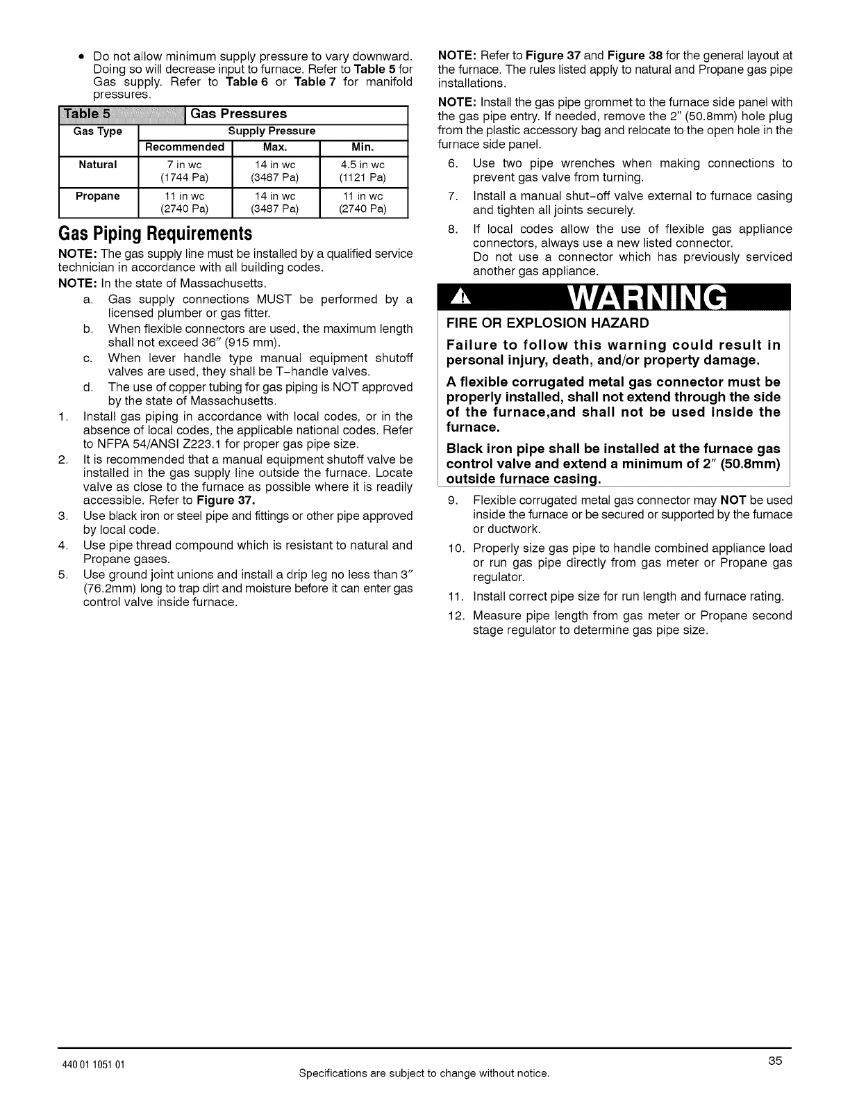
Do not allow minimum supply pressure to vary downward.
Doing so will decrease input to furnace. Refer to Table 5 for
Gas supply. Refer to Table 6 or Table 7 for manifold
pressures. GasPressures
GasType Supply Pressure
Recommended Max. Min.
Natural 7 in wc 14 in wc 4.5 in wc
(1744 Pa) (3487 Pa) (1121 Pa)
Propane 11in wc 14 in wc 11in wc
(2740 Pa) (3487 Pa) (2740 Pa)
Gas Piping Requirements
NOTE: The gas supply line must be installed by a qualified service
technician in accordance with all building codes.
NOTE: In the state of Massachusetts.
a. Gas supply connections MUST be performed by a
licensed plumber or gas fitter.
b. When flexible connectors are used, the maximum length
shall not exceed 36" (915 mm).
c. When lever handle type manual equipment shutoff
valves are used, they shall be T-handle valves.
d. The use of copper tubing for gas piping is NOT approved
by the state of Massachusetts.
1. Install gas piping in accordance with local codes, or in the
absence of local codes, the applicable national codes. Refer
to NFPA 54/ANSI Z223.1 for proper gas pipe size.
2. It is recommended that a manual equipment shutoff valve be
installed in the gas supply line outside the furnace. Locate
valve as close to the furnace as possible where it is readily
accessible. Refer to Figure 37.
3. Use black iron or steel pipe and fittings or other pipe approved
by local code.
4. Use pipe thread compound which is resistant to natural and
Propane gases.
5. Use ground joint unions and install a drip leg no less than 3"
(76.2mm) long to trap dirt and moisture before it can enter gas
control valve inside furnace.
NOTE: Refer to Figure 37 and Figure 38 for the general layout at
the furnace. The rules listed apply to natural and Propane gas pipe
installations.
NOTE: Install the gas pipe grommet to the furnace side panel with
the gas pipe entry. If needed, remove the 2" (50.8mm) hole plug
from the plastic accessory bag and relocate to the open hole in the
furnace side panel.
6. Use two pipe wrenches when making connections to
prevent gas valve from turning.
7. Install a manual shut-off valve external to furnace casing
and tighten all joints securely.
8. If local codes allow the use of flexible gas appliance
connectors, always use a new listed connector.
Do not use a connector which has previously serviced
another gas appliance.
FIRE OR EXPLOSION HAZARD
Failure to follow this warning could result in
personal injury, death, and/or property damage.
Aflexible corrugated metal gas connector must be
properly installed, shall not extend through the side
of the furnace,and shall not be used inside the
furnace.
Black iron pipe shall be installed at the furnace gas
control valve and extend a minimum of 2" (50.8mm)
outside furnace casing.
9. Flexible corrugated metal gas connector may NOT be used
inside the furnace or be secured or supported by the furnace
or ductwork.
10. Properly size gas pipe to handle combined appliance load
or run gas pipe directly from gas meter or Propane gas
regulator.
11. Install correct pipe size for run length and furnace rating.
12. Measure pipe length from gas meter or Propane second
stage regulator to determine gas pipe size.
35
44001 105101 Specifications are subject to change without notice.
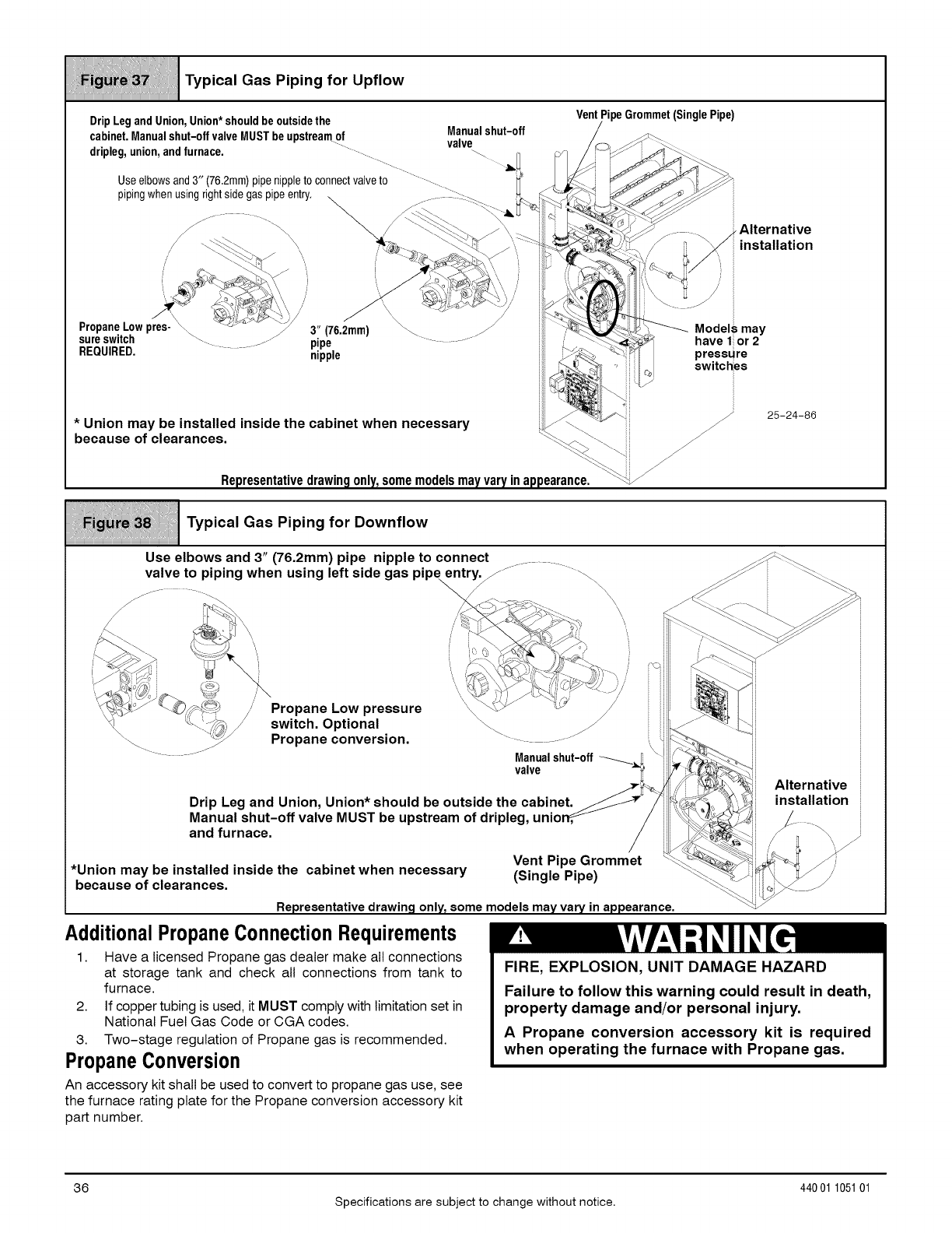
_i_=i_i_!_i_i_ii_i_iii_i_i_ii_llli_ll_ll_i
Typical Gas Piping for Upflow
DripLegandUnion,Union*shouldbeoutsidethe VentPipeGrommet(SinglePipe)
cabinet,Manualshut-offvalveMUSTbeupstreamof Manualshut-off /_
....... valve Cj->
dripleg,union,andfurnace. "......... _ ,_ _j /¢ _/_ _ i __
Useelbowsand3" (76.2mm)pipenippletoconnectvalveto .............. h_ |_"_'_" _J_f_
pipingwhenusingrightsidegaspipeentry.. _:.._ ,_ ,<_,k<_ __" i
_ "_ _/ "_ /\ .. iii _/._ ......... _Alternative
/-C_'_ \ __ _._ \'.-_41_'_-_ '!_ /_" _/i installation
vropane•Lowpres-'-,, ""_3" (76•2mm) \_ _ ill "'__._ Models may
sureSWllCn .......... pipe " .......... i_!;i /__ have 1 or 2
REQUIRED. ...... nipple iii _/_: _ pressure
switch,de
* Union may be installed inside the cabinet when necessary _ _ :: 25-24-86
because of clearances. "_. _\ ::
Representativedrawingonly,somemodelsmayvaryinappearance•_
,p,co,GooP,p,ng,orOown,,ow
Use elbows and 3" (76.2mm) pipe nipple to connect .........
valve to piping when using left side gas pipe entry. _J .......... '_ _ :_'_:z
"_ ......_t_/ Pro and conversion i c_ '_
P" " .......... \'i i ...... i
.............. Manualshut-off_ _ __ ii
valve _i_ ii
/._%_ ¢_\_ Alternative i
Drip Leg and Union, Union* should be outside the cabinet. /_ /_ _", _ installation
Manual shut-off valve MUST be upstream of dripleg, unior_---_- /i__ /- ......
and furnace, i __ /-1 _
.Vent Pipe Grommet _-_-_% _ _,
Union may be installed inside the cabinet when necessary "Sin le Pi e" "_.._.,_/ _ 1_
because of clearances, tg P )_ i ___ _
Representative drawing only, some models may vary in appearance• "_
AdditionalPropaneConnectionRequirements
1. Have a licensed Propane gas dealer make all connections
at storage tank and check all connections from tank to
furnace.
2. If copper tubing is used, it MUST comply with limitation set in
National Fuel Gas Code or CGA codes.
3. Two-stage regulation of Propane gas is recommended.
PropaneConversion
An accessory kit shall be used to convert to propane gas use, see
the furnace rating plate for the Propane conversion accessory kit
part number.
FIRE, EXPLOSION, UNIT DAMAGE HAZARD
Failure to follow this warning could result in death,
property damage and/or personal injury.
A Propane conversion accessory kit is required
when operating the furnace with Propane gas.
36
Specifications are subject to change without notice.
440 01 105101
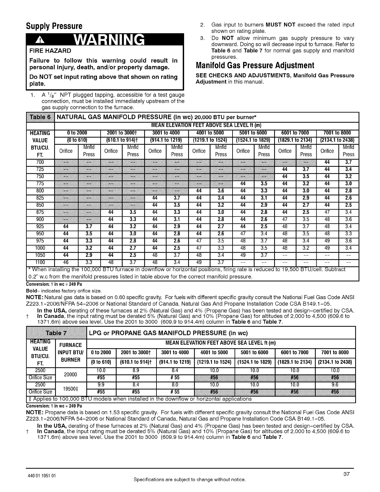
Supply Pressure
FIRE HAZARD
Failure to follow this warning could result in
personal injury, death, and/or property damage.
Do NOT set input rating above that shown on rating
plate.
2. Gas input to burners MUST NOT exceed the rated input
shown on rating plate.
3. Do NOT allow minimum gas supply pressure to vary
downward. Doing so will decrease inputto furnace. Refer to
Table 6 and Table 7 for normal gas supply and manifold
pressures.
ManifoldGas PressureAdjustment
SEE CHECKS AND ADJUSTMENTS, Manifold Gas Pressure
Adjustment in this manual.
7001to 8000
(2134.1to 2438)
Mnfld
Orifice Press
1. A 1/8" NPT plugged tapping, accessible for a test gauge
connection, must be installed immediately upstream of the
gas supply connection to the furnace.
_bJ_ NATURAL GAS MANIFOLD PRESSURE (in wc) 20,000 BTU per burner*
MEANELEVATIONFEETABOVE SEALEVELft (m}
0 to 2000 2001to 30001 3001to 4000 4001to 5000 5001 to 6000
(0to 610) (610.1to 914)t (914.1to 1219) (1219.1to 1524) (1524.1to 1829)
Mnfld Mnfld Mnfld Mnfld Mnfld
Orifice Orifice Orifice Orifice Orifice
Press Press Press Press Press
6001to 7000
(1829.1to 2134)
Mnfld
Orifice Press
:, _ 44 3.7
:.-,, 44 3.7 44 3.4
44 3.5 44 3.2
44 3.5 44 3.2 44 3.0
: 44 3.6 44 3.3 44 3.0 44 2.8
44 3.7 44 3.4 44 3.1 44 2.9 44 2.6
44 3.5 44 3.2 44 2.9 44 2.7 44 2.5
44 3.5 44 3.3 44 3.0 44 2.8 44 2.5 47 3.4
44 3.3 44 3.1 44 2.8 44 2.6 47 3.5 48 3.6
44 3.7 44 3.2 44 2.9 44 2.7 44 2.5 48 3.7 48 3.4
44 3.5 44 3.0 44 2.8 44 2.6 47 3.4 48 3.5 48 3.3
44 3.3 44 2.8 44 2.6 47 3.5 48 3.7 48 3.4 49 3.6
44 3.2 44 2.7 44 2.5 47 3.3 48 3.5 48 3.2 49 3.4
44 2.9 44 2.5 48 3.7 48 3.4 49 3.7 ........
46 3.3 48 3.7 48 3.4 49 3.7 ............
HEATING
VALUE
BTU/CU.
FT.
700
725
750
775
800
825
850
875
900
925
950
975
1000
1050
1100
*When installing the 100,000 BTU furnace in downflow or horizontal positions, firing rate is reduced to 19,500 BTU/celI. Subtract
0.2" w.c from the manifold pressures listed in table above for the correct manifold pressure.
Conversion:1inwc=249Pa
Bold- indicates factory orificesize.
NOTE: Natural gas data is based on 0.60 specific gravity. For fuels with different specific gravity consult the National Fuel Gas Code ANSI
Z223.1-2006/N FPA 54-2006 or National Standard of Canada, Natural Gas And Propane Installation Code CSA B149.1-05.
In the USA, derating of these furnaces at 2% (Natural Gas) and 4% (Propane Gas) has been tested and design-certified by CSA.
1- In Canada, the input rating must be derated 5% (Natural Gas) and 10% (Propane Gas) for altitudes of 2,000 to 4,500 (609.6 to
1371.6m) above sea level. Use the 2001 to 3000 (609.9 to 914.4m) column in Table 6 and Table 7.
HEATING FURNACE
VALUE INPUTBTU!
BTU/CU. BURNER
FT.
2500 20000
OrificeSize
2500
OrificeSize 19500:1:
LPG or PROPANE GAS MANIFOLD PRESSURE (in wc)
MEANELEVATIONFEETABOVESEALEVELft (m)
0to 2000 2001 to 3000t 3001 to 4000 4001to 5000 5001 to 6000
(0 to 610) (610.1to 914)t (914.1to 1219)
10.0 8.9 8.4
#55 #55 # 55
9.9 8.4 8.0
#55 #55 # 55
6001 to 7000
(1219.1to 1524) (1524.1to 1829) (1829.1to 2134)
10.0 10.0 10.0
7001to 8000
(2134.1to 2438)
10.0
10.0 10.0 10.0 9.6
$ Applies to 100,000 BTU models when installed in the downflow or horizontal applications
Conversion:1inwc=249Pa
NOTE: Propane data is based on 1.53 specific gravity. For fuels with different specific gravity consult the National Fuel Gas Code ANSI
Z223.1-2006/NFPA 54-2006 or National Standard of Canada, Natural Gas and Propane Installation Code CSA B149.1-05.
In the USA, derating of these furnaces at 2% (Natural Gas) and 4% (Propane Gas) has been tested and design-certified by CSA.
1- In Canada, the input rating must be derated 5% (Natural Gas) and 10% (Propane Gas) for altitudes of 2,000 to 4,500 (609.6 to
1371.6m) above sea level. Use the 2001 to 3000 (609.9 to 914.4m) column in Table 6 and Table 7.
37
44001 105101 Specifications are subject to change without notice.
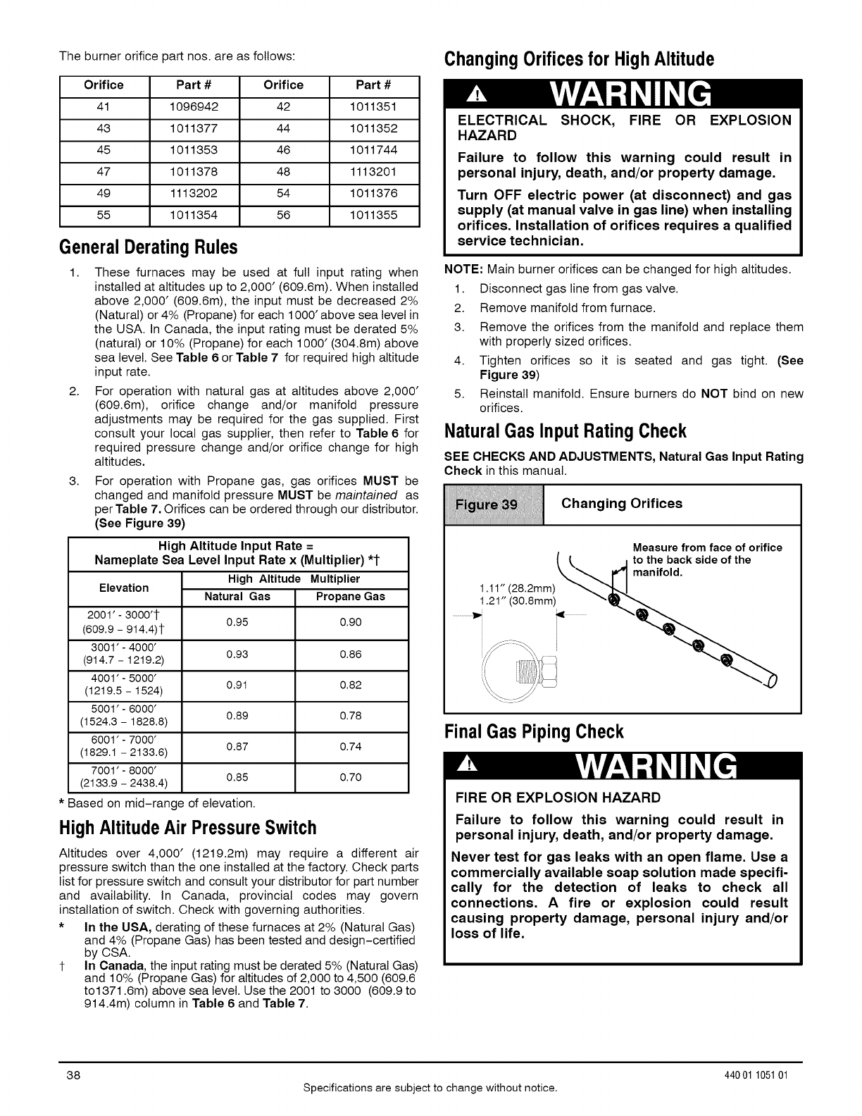
The burner orifice part nos. are as follows:
Orifice Part #Orifice Part #
41 1096942 42 1011351
43 1011377 44 1011352
45 1011353 46 1011744
47 1011378 48 1113201
49 1113202 54 1011376
55 1011354 56 1011355
GeneralDeratingRules
1. These furnaces may be used at full input rating when
installed at altitudes up to 2,000' (609.6m). When installed
above 2,000' (609.6m), the input must be decreased 2%
(Natural) or 4% (Propane) for each 1000' above sea level in
the USA. In Canada, the input rating must be derated 5%
(natural) or 10% (Propane) for each 1000' (304.8m) above
sea level. See Table 6 or Table 7 for required high altitude
input rate.
2. For operation with natural gas at altitudes above 2,000'
(609.6m), orifice change and/or manifold pressure
adjustments may be required for the gas supplied. First
consult your local gas supplier, then refer to Table 6 for
required pressure change and/or orifice change for high
altitudes.
3. For operation with Propane gas, gas orifices MUST be
changed and manifold pressure MUST be maintained as
per Table 7. Orifices can be ordered through our distributor.
(See Figure 39)
High Altitude Input Rate =
Nameplate Sea Level Input Rate x (Multiplier) "1-
High Altitude Multiplier
Elevation Natural Gas Propane Gas
2001' - 3000'1-
(609.9 -914.4)1- 0.95 0.90
3001' - 4000'
(914.7 - 1219.2) 0.93 0.86
4001' - 5000'
(1219.5 - 1524) 0.91 0.82
5001' - 6000'
(1524.3 - 1828.8) 0.89 0.78
6001' - 7000'
(1829.1 - 2133.6) 0.87 0.74
7001' - 8000'
(2133.9 - 2438.4) 0.85 0.70
* Based on mid-range of elevation.
HighAltitudeAir PressureSwitch
Altitudes over 4,000' (1219.2m) may require a different air
pressure switch than the one installed at the factory. Check parts
list for pressure switch and consult your distributor for part number
and availability. In Canada, provincial codes may govern
installation of switch. Check with governing authorities.
* In the USA, derating of these furnaces at 2% (Natural Gas)
and 4% (Propane Gas) has been tested and design-certified
by CSA.
1- In Canada, the input rating must be derated 5% (Natural Gas)
and 10% (Propane Gas) for altitudes of 2,000 to 4,500 (609.6
to1371.6m) above sea level. Use the 2001 to 3000 (609.9 to
914.4m) column in Table 6 and Table 7.
Changing Orifices for HighAltitude
ELECTRICAL SHOCK, FIRE OR EXPLOSION
HAZARD
Failure to follow this warning could result in
personal injury, death, and/or property damage.
Turn OFF electric power (at disconnect) and gas
supply (at manual valve in gas line) when installing
orifices. Installation of orifices requires a qualified
service technician.
NOTE: Main burner orifices can be changed for high altitudes.
1. Disconnect gas line from gas valve.
2. Remove manifold from furnace.
3. Remove the orifices from the manifold and replace them
with properly sized orifices.
4. Tighten orifices so it is seated and gas tight. (See
Figure 39)
5. Reinstall manifold. Ensure burners do NOT bind on new
orifices.
NaturalGas InputRatingCheck
SEE CHECKS AND ADJUSTMENTS, Natural Gas Input Rating
Check in this manual.
Changing Orifices
iiiiiiiiiiiiiiiiiiiiiiiiiiiiiiiiiiiiiiiiiiiiiiiiiiiiiiiiiiiiiiiiiiiiiiiiiiiiiiiiiiiiiiiiiiiiiiiiiiiiiiiiiiiiiiiiiiiiiiiiiiiiiiiiiiiiiiiiiiii
Measure from face of orifice
FinalGas PipingCheck
FIRE OR EXPLOSION HAZARD
Failure to follow this warning could result in
personal injury, death, and/or property damage.
Never test for gas leaks with an open flame. Use a
commercially available soap solution made specifi-
cally for the detection of leaks to check all
connections. A fire or explosion could result
causing property damage, personal injury and/or
loss of life.
38
Specifications are subject to change without notice.
440 01 105101
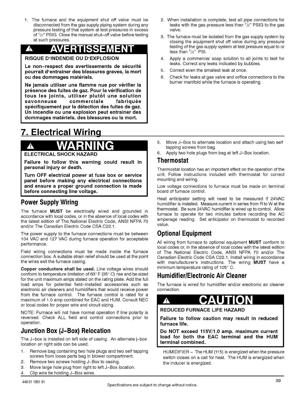
The furnace and the equipment shut off valve must be
disconnected from the gas supply piping system during any
pressure testing of that system at test pressures in excess
of 1/2_" PSlG. Close the manual shut-off valve before testing
at such pressures.
RISQUE D'INDENDIE OU D'EXPLOSION
Le non-respect des avertissements de securite
pourrait d'entrainer des blessures graves, la mort
ou des dommages materiels.
Ne jamais utiliser une flamme nue por verifier la
presence des fuites de gaz. Pour la verification de
tous les joints, utiliser plut6t une solution
savonneuse commerciale fabriquee
specifiquement pur la detection des fuites de gaz.
Un incendie ou une explosion peut entrainer des
dommages materiels, des blessures ou la mort.
2. When installation is complete, test all pipe connections for
leaks with the gas pressure less than 1/2" PSlG to the gas
valve.
3. The furnace must be isolated from the gas supply system by
closing the equipment shut off valve during any pressure
testing of the gas supply system at test pressure equal to or
less than 1/2" PSI.
4. Apply a commercial soap solution to all joints to test for
leaks. Correct any leaks indicated by bubbles.
5. Correct even the smallest leak at once.
6. Check for leaks at gas valve and orifice connections to the
burner manifold while the furnace is operating.
7. Electrical Wiring
ELECTRICAL SHOCK HAZARD
Failure to follow this warning could result in
personal injury or death.
Turn OFF electrical power at fuse box or service
panel before making any electrical connections
and ensure a proper ground connection is made
before connecting line voltage.
5. Move J-Box to alternate location and attach using two self
tapping screws from bag.
6. Apply two hole plugs from bag at left J-Box location.
Thermostat
Thermostat location has an important effect on the operation of the
unit. Follow instructions included with thermostat for correct
mounting and wiring.
Low voltage connections to furnace must be made on terminal
board of furnace control.
Power SupplyWiring
The furnace MUST be electrically wired and grounded in
accordance with local codes, or in the absence of local codes with
the latest edition of The National Electric Code, ANSI NFPA 70
and/or The Canadian Electric Code OSA O22.1.
The power supply to the furnace connections must be between
104 VAO and 127 VAO during furnace operation for acceptable
performance.
Field wiring connections must be made inside the furnace
connection box. A suitable strain relief should be used at the point
the wires exit the furnace casing.
Copper conductors shall be used. Line voltage wires should
conform to temperature limitation of 63° F (35° 0) rise and be sized
for the unit maximum amps stated on the rating plate. Add the full
load amps for potential field-installed accessories such as
electronic air cleaners and humidifiers that would receive power
from the furnace control. The furnace control is rated for a
maximum of 1.0 amp combined for EAO and HUM. Consult NEO
or local codes for proper wire and circuit sizing.
NOTE: Furnace will not have normal operation if line polarity is
reversed. Check ALL field and control connections prior to
operation.
JunctionBox (J-B0x) Relocation
The J-box is installed on left side of casing. An alternate j-box
location on right side can be used.
Heat anticipator setting wilt need to be measured if 24VAC
humidifier is installed. Measure current in series from R to W at the
thermostat. Be sure 24VA0 humidifier is wired up to control. Allow
furnace to operate for two minutes before recording the AO
amperage reading. Set anticipator on thermostat to recorded
value.
OptionalEquipment
All wiring from furnace to optional equipment MUST conform to
local codes or, in the absence of local codes with the latest edition
of The National Electric Code, ANSI NFPA 70 and/or The
Canadian Electric Code OSA O22.1. Install wiring in accordance
with manufacturer's instructions. The wiring MUST have a
minimum temperature rating of 105 ° 0.
Humidifier/Electr0nicAir Cleaner
The furnace is wired for humidifier and/or electronic air cleaner
connection.
REDUCED FURNACE LIFE HAZARD
Failure to follow caution may result in reduced
furnace life.
Do NOT exceed 115V/1.0 amp. maximum current
load for both the EAC terminal and the HUM
terminal combined.
1. Remove bag containing two hole plugs and two self tapping
screws from loose parts bag in blower compartment.
2. Remove two screws holding J-Box to casing.
3. Move large hole plug from right to left J-Box location.
4. Clip wire tie holding J-Box wires.
HUMIDIFIER - The HUM (115) is energized when the pressure
switch closes on a call for heat. The HUM is energized when
the inducer is energized.
39
44001 105101 Specifications are subject to change without notice.
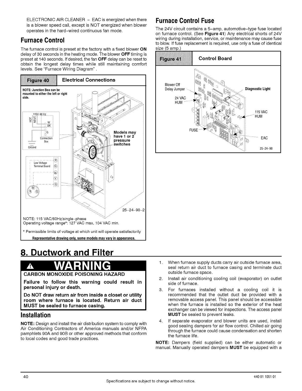
ELECTRONIC AIR CLEANER - EAC is energized when there
is a blower speed call, except is NOT energized when blower
operates in the hard-wired continuous fan mode.
FurnaceControl
The furnace control is preset at the factory with a fixed blower ON
delay of 30 seconds in the heating mode. The blower OFF timing is
preset at 140 seconds. If desired, the fan OFF delay can be reset to
obtain the longest delay times while still maintaining comfort
levels. See "Furnace Wiring Diagram".
Electrical Connections
NOTE:JunctionBox canbe
mountedto eitherthe left or right
side.
115V.60 Hz
[i Connection
' Box
Ground
Low Voltage
TerminalBoard
i
J
Models may
have 1 or 2
pressure
switches
\\ J_225-24-90-2
j-
NOTE: 115 VAC/6OHz/single-phase
Operatingvoltage range*: 127 VAC max, 104 VAC min.
* Permissible limits of voltage at which unit will operate satisfactorily
somemodels
FurnaceControl Fuse
The 24V circuit contains a 5-amp, automotive-type fuse located
on furnace control. (See Figure 41) Any electrical shorts of 24V
wiring during installation, service, or maintenance may cause fuse
to blow. If fuse replacement is required, use only a fuse of identical
size (5 amp.)
Contro,
iiiiiiiiiiiiiiiiiiiiiiiiiiiiiiiiiiiiiiiiiiiiiiiiiiiiiiiiiiiiiiiiiiiiiiiiiiiiiiiiiiiiiiiiiiiiiiiiiiiiiiiiiiiiiiiiiiiiiiiiiiiiiiiiiiiiiiiiiiiiiiiiiiii
BlowerOff %_
DelayJumper _ _
24VAC . .._
HUM..........__ J
FUSEi
-_ 25-24-98
8. Ductwork and Filter
CARBON MONOXIDE POISONING HAZARD
Failure to follow this warning could result in
personal injury or death.
Do NOT draw return air from inside a closet or utility
room where furnace is located. Return air duct
MUST be sealed to furnace casing.
Installation
NOTE: Design and install the air distribution system to comply with
Air Conditioning Contractors of America manuals and/or NFPA
pamphlets 90A and 90B or other approved methods that conform
to local codes and good trade practices.
1. When furnace supply ducts carry air outside furnace area,
seal return air duct to furnace casing and terminate duct
outside furnace space.
2. Install air conditioning cooling coil (evaporator) on outlet
side of furnace.
3. For furnaces installed without a cooling coil it is
recommended that the outlet duct be provided with a
removable access panel. This panel should be accessible
when the furnace is installed so the exterior of the heat
exchanger can be viewed for inspections. The access panel
MUST be sealed to prevent leaks.
4. If separate evaporator and blower units are used, install
good sealing dampers for air flow control. Chilled air going
through the furnace could cause condensation and shorten
the furnace life.
NOTE: Dampers (field supplied) can be either automatic or
manual. Manually operated dampers MUST be equipped with a
40
Specifications are subject to change without notice.
44001 105101
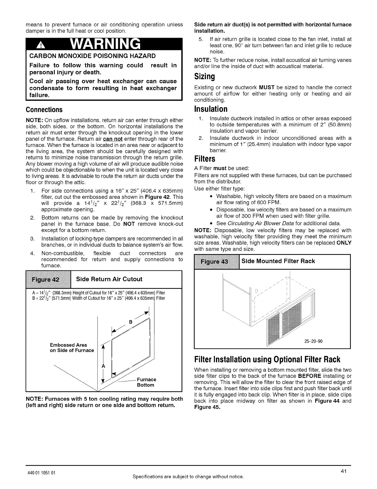
means to prevent furnace or air conditioning operation unless
damper is in the full heat or cool position.
CARBON MONOXIDE POISONING HAZARD
Failure to follow this warning could result in
personal injury or death.
Cool air passing over heat exchanger can cause
condensate to form resulting in heat exchanger
failure.
Connections
NOTE: On upflow installations, return air can enter through either
side, both sides, or the bottom. On horizontal installations the
return air must enter through the knockout opening in the lower
panel of the furnace. Return air can not enter through rear of the
furnace. When the furnace is located in an area near or adjacent to
the living area, the system should be carefully designed with
returns to minimize noise transmission through the return grille.
Any blower moving a high volume of air will produce audible noise
which could be objectionable to when the unit is located very close
to living areas. It is advisable to route the return air ducts under the
floor or through the attic.
1. For side connections using a 16" x 25" (406.4 x 635mm)
filter, cut out the embossed area shown in Figure 42. This
will provide a 141/2" x 221/2" (368.3 x 571.5mm)
approximate opening.
2. Bottom returns can be made by removing the knockout
panel in the furnace base. Do NOT remove knock-out
except for a bottom return.
Installation of locking-type dampers are recommended in all
branches, or in individual ducts to balance system's air flow.
Non-combustible, flexible duct connectors are
recommended for return and supply connections to
3.
4.
furnace.
Side Return Air Cutout
iiiiiiiiiiiiiiiiiiiiiiiiiiiiiiiiiiiiiiiiiiiiiiiiiiiiiiiiiiiiiiiiiiiiiiiiiiiiiiiiiiiiiiiiiiiiiiiiiiiiiiiiiiiiiiiiiiiiiiiiiiiiiiiiiiiiiiiiiiiiiiii
A= 141/2"(368,3mm)HeightofCutoutfor16"x25" (406,4x 635mm)
B= 221/2" (571.5mm)WidthofCutoutfor16"x25" (406.4x 635mm
Filter
Filter
Embossed Area
on Side of Furnace
iS >
NOTE: Furnaces with 5 ton cooling rating may require both
(left and right) side return or one side and bottom return.
Side return air duct(s) is not permitted with horizontal furnace
installation.
5. If air return grille is located close to the fan inlet, install at
least one, 90° air turn between fan and inlet grille to reduce
noise.
NOTE: To further reduce noise, install acoustical air turning vanes
and/or line the inside of duct with acoustical material.
Sizing
Existing or new ductwork MUST be sized to handle the correct
amount of airflow for either heating only or heating and air
conditioning.
Insulation
1. Insulate ductwork installed in attics or other areas exposed
to outside temperatures with a minimum of 2" (50.8mm)
insulation and vapor barrier.
2. Insulate ductwork in indoor unconditioned areas with a
minimum of 1" (25.4mm) insulation with indoor type vapor
barrier.
Filters
A Filter must be used:
Filters are not supplied with these furnaces, but can be purchased
from the distributor.
Use either filter type:
• Washable, high velocity filters are based on a maximum
air flow rating of 600 FPM.
• Disposable, low velocity filters are based on a maximum
air flow of 300 FPM when used with filter grille.
• See Circulating Air Blower Data for additional data.
NOTE: Disposable, low velocity filters may be replaced with
washable, high velocity filter providing they meet the minimum
size areas. Washable, high velocity filters can be replaced ONLY
with same type and size.
Side Mounted Filter Rack
25-20-90
FilterInstallationusing OptionalFilter Rack
When installing or removing a bottom mounted filter, slide the two
side filter clips to the back of the furnace BEFORE installing or
removing. This will allow the filter to clear the front raised edge of
the furnace. Insert filter into side clips first and push filter back until
it is fully engaged into back clip. When filter is in place, slide clips
back into place midway on filter as shown in Figure 44 and
Figure 45.
41
44001 105101 Specifications are subject to change without notice.
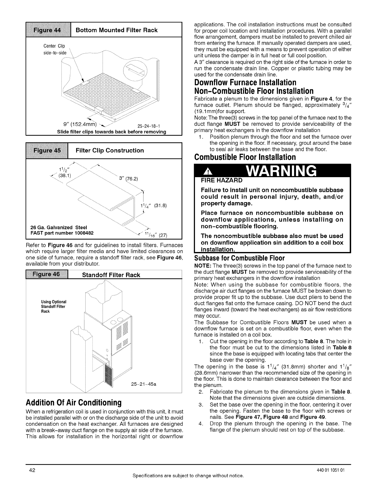
Bottom Mounted Filter Rack
/
9" (152.4mm) _,_jz 25-24-18-1
Slide filter clips towards back before removing
Filter Clip Construction
11/2 " _/ \\
:76.2)
11/4" (31.8)
26 Ga. Galvanized Steel
FAST part number 1008482
Refer to Figure 46 and for guidelines to install filters. Furnaces
which require larger filter media and have limited clearances on
one side of furnace, require a standoff filter rack, see Figure 46,
available from your distributor.
Standoff Filter Rack
UsingOptional
Standoff Filter
Rack
25-21-45a
AdditionOfAir Conditioning
When a refrigeration coil is used in conjunction with this unit, it must
be installed parallel with or on the discharge side of the unit to avoid
condensation on the heat exchanger. All furnaces are designed
with a break-away duct flange on the supply air side of the furnace.
This allows for installation in the horizontal right or downfiow
applications. The coil installation instructions must be consulted
for proper coil location and installation procedures. With a parallel
flow arrangement, dampers must be installed to prevent chilled air
from entering the furnace. If manually operated dampers are used,
they must be equipped with a means to prevent operation of either
unit unless the damper is in full heat or full cool position.
A 3" clearance is required on the right side of the furnace in order to
run the condensate drain line. Copper or plastic tubing may be
used for the condensate drain line.
DownflowFurnaceInstallation
Non-CombustibleFloor Installation
Fabricate a plenum to the dimensions given in Figure 4, for the
furnace outlet. Plenum should be flanged, approximately 3/4"
(19.1 mm)for support.
Note: The three(3) screws in the top panel of the furnace next to the
duct flange MUST be removed to provide serviceability of the
primary heat exchangers in the downflow installation
1. Position plenum through the floor and set the furnace over
the opening in the floor. If necessary, grout around the base
to seal air leaks between the base and the floor.
CombustibleFloor Installation
FIRE HAZARD
Failure to install unit on noncombustible subbase
could result in personal injury, death, and/or
property damage.
Place furnace on noncombustible subbase on
downflow applications, unless installing on
non-combustible flooring.
The noncombustible subbase also must be used
on downflow application sin addition to a coil box
installation.
Subbase for Combustible Floor
NOTE: The three(3) screws in the top panel of the furnace next to
the duct flange MUST be removed to provide serviceability of the
primary heat exchangers in the downflow installation
Note: When using the subbase for combustible floors, the
discharge air duct flanges on the furnace MUST be broken down to
provide proper fit up to the subbase. Use duct pliers to bend the
duct flanges flat onto the furnace casing. DO NOT bend the duct
flanges inward (toward the heat exchangers) as air flow restrictions
may occur.
The Subbase for Combustible Floors MUST be used when a
downflow furnace is set on a combustible floor, even when the
furnace is installed on a coil box.
1. Cut the opening in the floor according to Table 8. The hole in
the floor must be cut to the dimensions listed in Table 8
since the base is equipped with locating tabs that center the
base over the opening.
The opening in the base is 11/4" (31.8mm) shorter and 11/8"
(28.6mm) narrower than the recommended size of the opening in
the floor. This is done to maintain clearance between the floor and
the plenum.
2. Fabricate the plenum to the dimensions given in Table 8.
Note that the dimensions given are outside dimensions.
3. Set the base over the opening in the floor, centering it over
the opening. Fasten the base to the floor with screws or
nails. See Figure 47, Figure 48 and Figure 49.
4. Drop the plenum through the opening in the base. The
flange of the plenum should rest on top of the subbase.
42
Specifications are subject to change without notice.
44001 105101
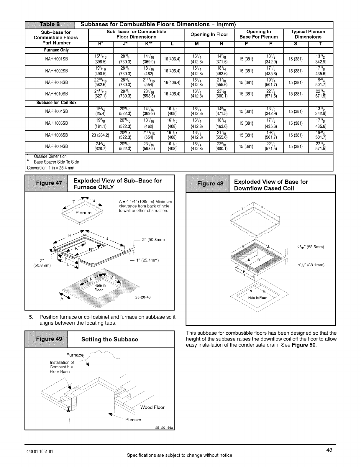
!!i!
Sub-base for
Combustible Floors
Part Number
FurnaceOnly
1511/16 28_/4 14u/16 16(406.4)
NAHH001SB (398.5) (730.3) (369.9)
19=/16 28_/4 18_/16 16(406.4)
NAHH002SB (490.5) (730.3) (462)
221=/16 28_/4 211_/16 16(406.4)
NAHH003SB (582.6) (730.3) (554)
241t/16 28_/4 23u/16
NAHH010SB (627.1) (730.3) (598.5) 16(406.4)
Subbasefor CoilBox
15"_/4 20u/16 14u/16 161/16
NAHH004SB (25.4) (522.3) (369.9) (408)
NAHH005SB 19_/8 20u/16 18_/16 161/16
(181.1) (522.3) (462) (408)
20u/16 21 _'_/16 16_/16
NAHH006SB 23 (284.2) (522.3) (554) (408)
2M/4 20u/16 23u/16 161/16
NAHH009SB (628.7) (522.3) (598.5) (408)
OutsideDimension
** BaseSpacerSideToSide
Conversion:1 in =25.4 mm
Subbases for Combustible Floors Dimensions -in(mm)
Sub-base for Combustible
Floor Dimensions Opening In Floor
H_J* K** L M N
Opening In
Base For Plenum
P R
16_/4 14_/8 13_/2
(412.8) (371.5) 15 (381) (342.9)
161/4 181/4 171/8
(412.8) (463.6) 15 (381) (435.6)
161/4 21l/8 19_/4
(412.8) (555.6) 15 (381) (501.7)
16 _/4 23_/8 22 _/2
(412.8) (600.1) 15 (381) (571.5)
Typical Plenum
Dimensions
S
15 (381) 13_/2
(342.9)
17Y8
15 (381) (435.6)
19_/4
15 (381) (501.7)
221/2
15 (381) (571.5)
16_/4 14=/8 13_/2
(412.8) (371.5) 15 (381) (342.9)
161/4 181/4 171/8
15 (381)
(412.8) (463.6) (435.6)
16_/4 21_/8 19'J/4
(412.8) (555.6) 15 (381) (501.7)
16 _/4 23=/8 22 _/2
(412.8) (600.1) 15 (381) (571.5)
13112
15 (381) (342.9)
17Y8
15 (381) (435.6)
19_/4
15 (381) (501.7)
221/2
15 (381) (571.5)
i; ;i;i;
Exploded View of Sub-Base for
Furnace ON LY
--_'_ s
_/ Plenum _y_
A = 4 1/4" (108mm) Minimum
clearance from back of hole
to wall or other obstruction.
I _- 2" (50.8mm)
(50.8mm) L'_-_
5. Position furnace or coil cabinet and furnace on subbase so it
aligns between the locating tabs.
F|g_49 Setting the Subbase
iiiiiiiiiiiiiiiiiiiiiiiiiiiiiiiiiiiiiiiiiiiiiiiiiiiiiiiiiiiiiiiiiiiiiiiiiiiiiiiiiiiiiiiiiiiiiiiiiiiiiiiiiiiiiiiiiiiiiiiiiiiiiiiiiiiiiiiiiiiiiiii
..../\./ -.
Furnace_ y/ _'\
Installation of J -'_
Oombustible i --
Floor Base i
ii _._Wo_dod Floor
,_... --... Plenum
25-20-46a
i;i i;
Exploded View of Base for
Downflow Cased Coil
21/2" (63.5mm)
11/2" (38.1mm)
This subbase for combustible floors has been designed so that the
height of the subbase raises the downflow coil off the floor to allow
easy installation of the condensate drain. See Figure 50.
43
44001 105101 Specifications are subject to change without notice.
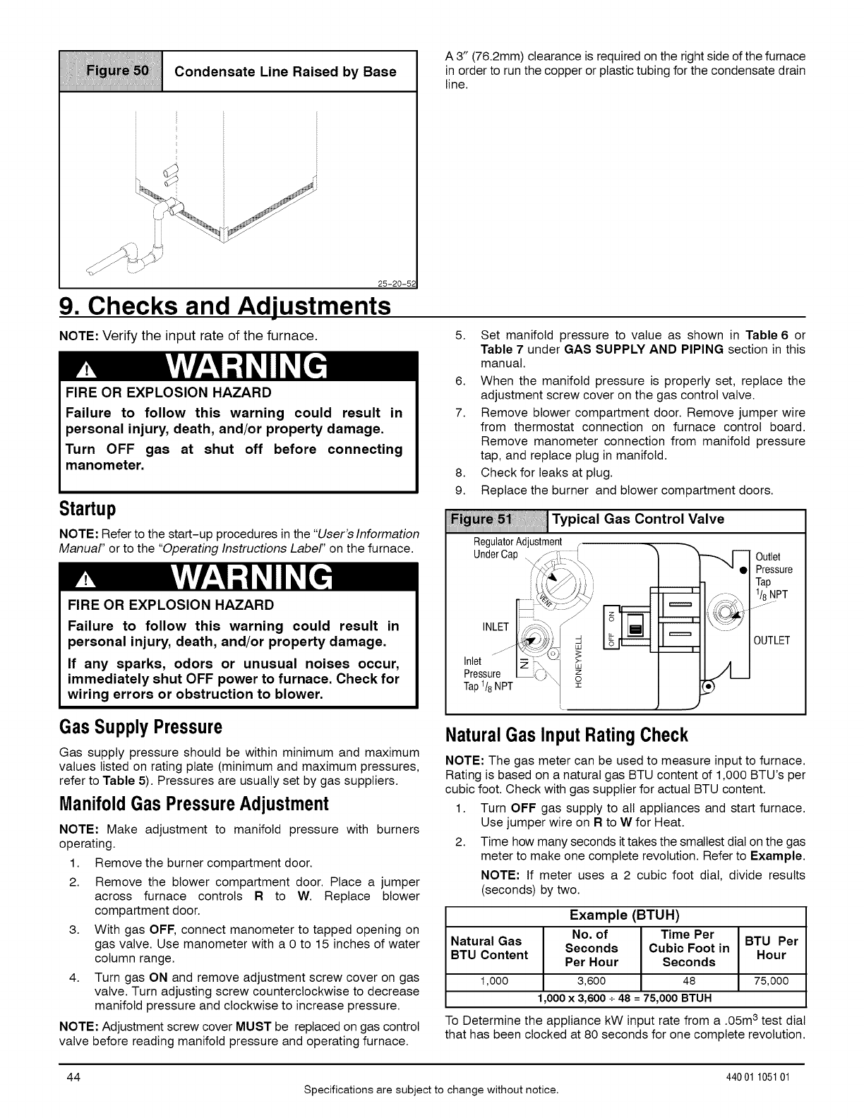
iii iiiiii Oondenoote.,ne.o,oed..Boca
iiiiiiiiiiiiiiiiiiiiiiiiiiiiiiiiiiiiiiiiiiiiiiiiiiiiiiiiiiiiiiiiiiiiiiiiiiiiiiiiiiiiiiiiiiiiiiiiiiiiiiiiiiiiiiiiiiiiiiiiiiiiiiiiiiiiiiiiiiiiiiii
25-20-52
9. Checks and Adjustments
NOTE: Verify the input rate of the furnace.
A 3" (76.2mm) clearance is required on the right side of the furnace
in order to run the copper or plastic tubing for the condensate drain
FIRE OR EXPLOSION HAZARD
Failure to follow this warning could result in
personal injury, death, and/or property damage.
Turn OFF gas at shut off before connecting
manometer.
Startup
NOTE: Refer to the start-up procedures in the "User's Information
Manual" or to the "Operating Instructions Label" on the furnace.
FIRE OR EXPLOSION HAZARD
Failure to follow this warning could result in
personal injury, death, and/or property damage.
If any sparks, odors or unusual noises occur,
immediately shut OFF power to furnace. Check for
wiring errors or obstruction to blower.
line.
5. Set manifold pressure to value as shown in Table 6or
Table 7 under GAS SUPPLY AND PIPING section in this
manual.
6. When the manifold pressure is properly set, replace the
adjustment screw cover on the gas control valve.
7. Remove blower compartment door. Remove jumper wire
from thermostat connection on furnace control board.
Remove manometer connection from manifold pressure
tap, and replace plug in manifold.
8. Check for leaks at plug.
9. Replace the burner and blower compartment doors.
Fig_51 _:, 11Typical Gas Control Valve
RegulatorAdjustment
UnderCap
INLET
Inlet
Pressure z_
Tap 118NPT o
Outlet
Pressure
Tap
1/8NPT
_) I
OUTLET
Gas Supply Pressure
Gas supply pressure should be within minimum and maximum
values listed on rating plate (minimum and maximum pressures,
refer to Table 5). Pressures are usually set by gas suppliers.
ManifoldGas PressureAdjustment
NOTE: Make adjustment to
operating.
manifold pressure with burners
1. Remove the burner compartment door.
2. Remove the blower compartment door. Place a jumper
across furnace controls Rto W. Replace blower
compartment door.
3. With gas OFF, connect manometer to tapped opening on
gas valve. Use manometer with a 0 to 15 inches of water
column range.
4. Turn gas ON and remove adjustment screw cover on gas
valve. Turn adjusting screw counterclockwise to decrease
manifold pressure and clockwise to increase pressure.
NOTE: Adjustment screw cover MUST be replaced on gas control
valve before reading manifold pressure and operating furnace.
NaturalGas InputRatingCheck
NOTE: The gas meter can be used to measure input to furnace.
Rating is based on a natural gas BTU content of 1,000 BTU's per
cubic foot. Check with gas supplier for actual BTU content.
1. Turn OFF gas supply to all appliances and start furnace.
Use jumper wire on R to W for Heat.
2. Time how many seconds it takes the smallest dial on the gas
meter to make one complete revolution. Refer to Example.
NOTE: If meter uses a 2 cubic foot dial, divide results
(seconds) by two.
Example (BTUH)
No. of Time Per
Natural Gas BTU Per
Seconds Cubic Foot in
BTU Content Hour
Per Hour Seconds
1,000 3,600 48 75,000
1,000x 3,600 +48 =75,000 BTUH
To Determine the appliance kW input rate from a .05m 3 test dial
that has been clocked at 80 seconds for one complete revolution.
44
Specifications are subject to change without notice.
440 01 105101
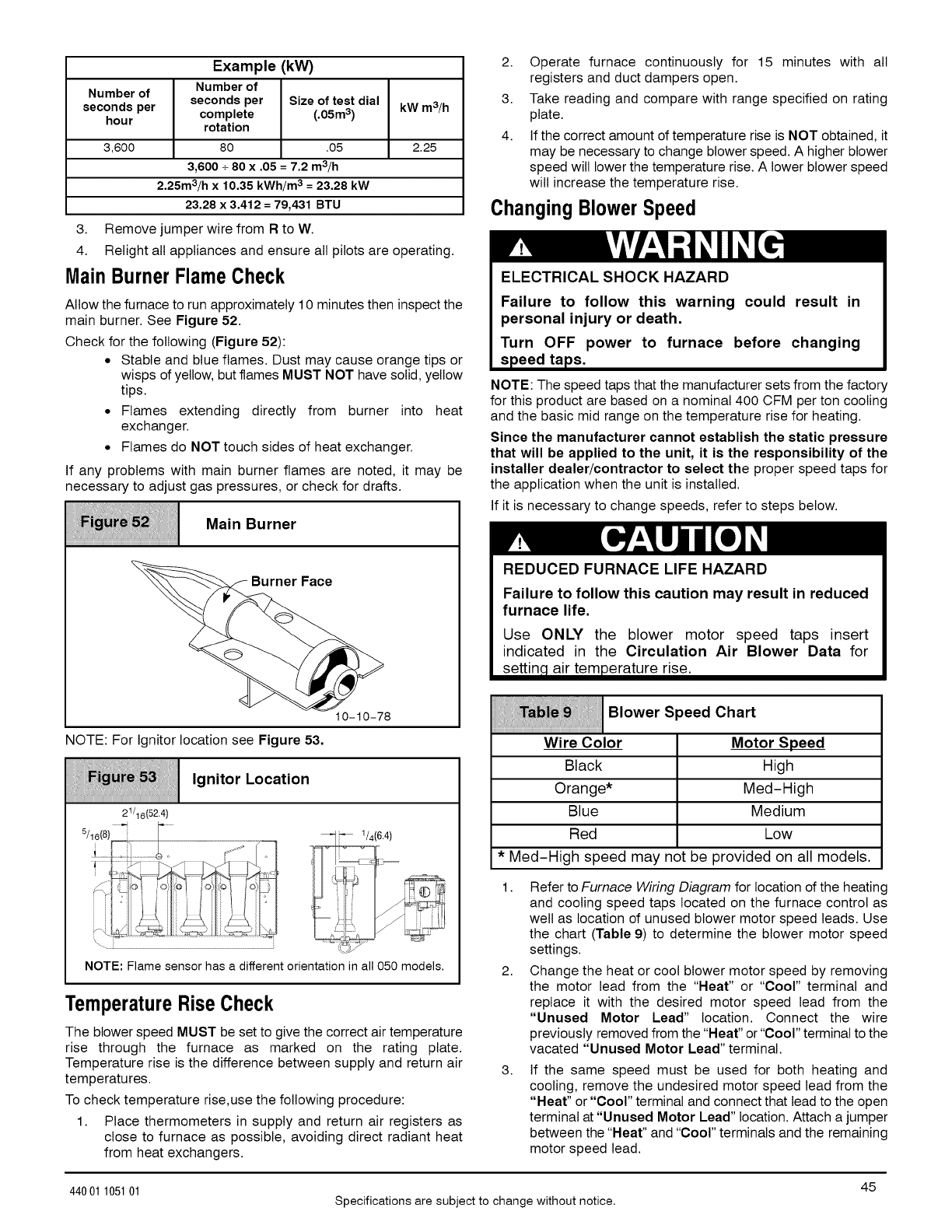
Example (kW)
Number of
Number of
seconds per seconds per Size of test dial
hour complete (.05m3) kW m3/h
rotation
3,600 80 .05 2.25
3,600 +80 x .05 =7.2 m3/h
2.25m3/h x 10.35 kWh/m 3 = 23.28 kW
23.28 x 3.412 = 79,431 BTU
3. Remove jumper wire from Rto W.
4. Relight all appliances and ensure all pilots are operating.
Main BurnerFlameCheck
Allow the furnace to run approximately 10 minutes then inspect the
main burner. See Figure 52.
Check for the following (Figure 52):
• Stable and blue flames. Dust may cause orange tips or
wisps of yellow, but flames MUST NOT have solid, yellow
tips.
• Flames extending directly from burner into heat
exchanger.
• Flames do NOT touch sides of heat exchanger.
If any problems with main burner flames are noted, it may be
necessary to adjust gas pressures, or check for drafts.
Main Burner
, Faoe
10-10-78
NOTE: For Ignitor location see Figure 53.
,gn,tor,o ot,on
iiiiiiiiiiiiiiiiiiiiiiiiiiiiiiiiiiiiiiiiiiiiiiiiiiiiiiiiiiiiiiiiiiiiiiiiiiiiiiiiiiiiiiiiiiiiiiiiiiiiiiiiiiiiiiiiiiiiiiiiiiiiiiiiiiiiiiiiiiiiiiii
21/16(52.4)
5/16(8) __"
NOTE: Flame sensor has a different orientation in all 050 models.
TemperatureRiseCheck
The blower speed MUST be set to give the correct air temperature
rise through the furnace as marked on the rating plate.
Temperature rise is the difference between supply and return air
temperatures.
To check temperature rise,use the following procedure:
1. Place thermometers in supply and return air registers as
close to furnace as possible, avoiding direct radiant heat
from heat exchangers.
2. Operate furnace continuously for 15 minutes with all
registers and duct dampers open.
3. Take reading and compare with range specified on rating
plate.
4. If the correct amount of temperature rise is NOT obtained, it
may be necessary to change blower speed. A higher blower
speed will lower the temperature rise. A lower blower speed
will increase the temperature rise.
ChangingBlowerSpeed
ELECTRICAL SHOCK HAZARD
Failure to follow this warning could result in
personal injury or death.
Turn OFF power to furnace before changing
speed taps.
NOTE: The speed taps that the manufacturer sets from the factory
for this product are based on a nominal 400 CFM per ton cooling
and the basic mid range on the temperature rise for heating.
Since the manufacturer cannot establish the static pressure
that will be applied to the unit, it is the responsibility of the
installer dealer/contractor to select the proper speed taps for
the application when the unit is installed.
If it is necessary to change speeds, refer to steps below.
REDUCED FURNACE LIFE HAZARD
Failure to follow this caution may result in reduced
furnace life.
Use ONLY the blower motor speed taps insert
indicated in the Circulation Air Blower Data for
settin_ air temperature rise.
Wire Color
Black
Orange*
Blue
Red
Blower Speed Chart
Motor Speed
High
Med-High
Medium
Low
* Med-High speed may not be provided on all models.
1. Refer to Furnace Wiring Diagram for location of the heating
and cooling speed taps located on the furnace control as
well as location of unused blower motor speed leads. Use
the chart (Table 9) to determine the blower motor speed
settings.
2. Change the heat or cool blower motor speed by removing
the motor lead from the "Heat" or "Cool" terminal and
replace it with the desired motor speed lead from the
"Unused Motor Lead" location. Connect the wire
previously removed from the "Heat" or "Cool" terminal to the
vacated "Unused Motor Lead" terminal.
3. If the same speed must be used for both heating and
cooling, remove the undesired motor speed lead from the
"Heat" or "Cool" terminal and connect that lead to the open
terminal at "Unused Motor Lead" location. Attach a jumper
between the "Heat" and "Cool" terminals and the remaining
motor speed lead.
45
44001 105101 Specifications are subject to change without notice.
Note: For motors with (4)speed leads, itwill be necessary to
tape off the terminal of the motor speed lead removed from
the "Heat" or "coor' terminal with electrical tape since an
open terminal wilt not be available at the "Unused Motor
Lead" location.
Continuous-Fan Operation using"G"
Energizing the "G" terminal on the furnace control provides
continuous fan operation. This is done by connecting the G
terminal of the thermostat to the G terminal on the furnace control.
When the FAN switch is turned from auto to ON the fan will operate
continuously at "HEAT" speed. EAC wilt be energized in this
mode.
NOTE: In heating, the fan will turn off during furnace ignition and
warm up then restart at heating speed.
Hard Wired ContinuousFan Operation
A terminal is provided on the furnace control board located in the
circulating blower compartment for operation of the continuous fan
option. This connection is intended for the low speed motor tap,
and has a lower contact rating (8 amps) than the heat and cool
10. Furnace Maintenance
taps. When the low speed blower lead is connected to this
terminal, this will provide low speed blower operation whenever
the other two speeds (Heat or Cool) are not energized.
Thoroughly check the system after modification to ensure the
proper operation of the circulating air blower in all modes of
operation.
Separatespeedselectionsfor Heat,Cool, and
ContinuousFan
Connect low speed lead from circulating motor to the "Cont."
terminal at the furnace control. The appropriate motor leads
should already be connected to the "Heat" and "coor' terminals.
Heatingand ContinuousBlowerSpeedthe
Same
If it is necessary to operate the heating speed and continuous
blower speed using the same blower speed, connect a jumper
between the "Heat" and "Cont." terminals on the furnace control.
Note: There should be only ONE motor lead going to the "Heat"
and "Cont." terminals.
FIRE, EXPLOSION, OR CARBON MONOXIDE
HAZARDS.
Failure to follow this warning could result in
personal injury, death and/or property damage.
It is recommended that the furnace be inspected
and serviced on an annual basis (before the heating
season) by a qualified service technician.
ELECTRICAL SHOCK, FIRE OR EXPLOSION
HAZAR D
Failure to follow this warning could result in
personal injury, death and/or property damage.
•Before servicing, disconnect all electrical
power to furnace.
•When servicing controls, label all wires prior to
disconnecting. Reconnect wires correctly.
• Verify proper operation after servicing.
See "User's Information Manual" and the "Service Manual".
46
Specifications are subject to change without notice.
440 01 105101

11. Sequence of Operation & Diagnostics
The following is the normal operating sequence.
Cooling(Y) Request:
24VAC signals applied to Y & G terminals of FCB (furnace control board)
• Cool motor speed is energized after 5 second Cool Fan On Delay time.
Y & G signals removed from FCB
• Cool motor speed is de-energized after 90 second Cool Fan Off Delay time.
ContinuousCirculatingFan(G) Request:
24 VAC signal is applied to G terminal of the FCB.
• Heat motor speed is energized without delay.
G signal removed from FCB.
• Heat motor speed is de-energized after 5 second delay.
NOTE 1) Furnace de-energizes the fan during the heat exchanger warm-up period on a call for Heating that occurs during a G request
unless a blower motor lead is connected to the Cont terminal on the FOB, in which case see NOTE 2).
NOTE 2) Heating or Cooling requests received during a Fan request cause the fan speed to change to the appropriate heat or cool
speed after the Fan on Delay time expires. The fan returns to continuous circulating speed after the selected Fan Off Delay time expires
following loss of the Heating or Cooling request.
ContinuousCirculatingFanHard-Wired (Cont) Request:
Field selected low speed motor tap installed on "CONT" terminal.
• Low speed is energized when power applied to furnace. Operates at this speed continuously while there are no other
blower demands from furnace control. Fan demands from furnace control for heat, cool or "G" will override hard-wired speed tap.
NOTE 3) EAC is NOT active for hard-wired mode but IS active for fan demands from furnace control for heat, cool and "G".
Heating(W) Request:
Heating (W) Request:
• 24 VAC signal applied to W terminal of FOB.
• Inducer motor turns on and the pressure switch(es) close(s).
• Following a 15 second prepurge delay, after the pressure switches closes, the igniter begins a 17 second warm-up.
• The gas valve is energized, the main burners light and flame is sensed.
• The igniter is de-energized after the main burners ignite.
• FOB will delay blower operation for the 30 seconds timed from the opening of the gas valve.
W signal removed from FCB.
• The gas valve de-energizes and the main burners go out.
• The inducer runs for a 15 second postpurge period.
• The fan stays at Heat speed.
• The fan de-energizes after the selected Heat Fan Off Delay time expires, timed from the gas valve de-energizing.
HUMIDIFIER - The 24V HUM is energized when the pressure switch closes on a call for heat. The 115V HUM (called HUM on Control)
is energized when the inducer is energized.
ELECTRONIC AIR CLEANER - EAC is energized when there isa blower speed call. It is NOT energized when blower operates in the
hard-wired continuous fan mode.
NOTE 4) If a new Heating request arrives while the control is waiting in the Heat Fan Off Delay time, the FCB will wait for the selected
Heat Fan Off Delay then start a new heating cycle as long as the heat call remains.
47
44001 105101 Specifications are subject to change without notice.
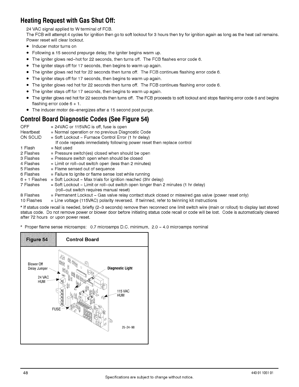
Heating Requestwith Gas ShutOff:
24 VAC signal applied to W terminal of FCB.
The FOB will attempt 4 cycles for ignition then go to soft lockout for 3 hours then try for ignition again as long as the heat call remains.
Power reset will clear lockout.
• Inducer motor turns on
• Following a 15 second prepurge delay, the igniter begins warm up.
• The igniter glows red-hot for 22 seconds, then turns off. The FOB flashes error code 6.
• The igniter stays off for 17 seconds, then begins to warm up again.
• The igniter glows red hot for 22 seconds then turns off. The FOB continues flashing error code 6.
• The igniter stays off for 17 seconds, then begins to warm up again.
• The igniter glows red hot for 22 seconds then turns off. The FOB continues flashing error code 6.
• The igniter stays off for 17 seconds, then begins to warm up again.
• The igniter glows red hot for 22 seconds then turns off. The FOB proceeds to soft lockout and stops flashing error code 6 and begins
flashing error code 6 + 1.
• The inducer motor de-energizes after a 15 second post purge.
ControlBoardDiagnosticCodes (SeeFigure54)
OFF = 24VAC or 115VAC is off, fuse is open
Heartbeat = Normal operation or no previous Diagnostic Code
ON SOLID = Soft Lockout - Furnace Control Error (1 hr delay)
If code repeats immediately following power reset then replace control
1 Flash = Not used
2 Flashes = Pressure switch(es) closed when should be open
3 Flashes = Pressure switch open when should be closed
4 Flashes = Limit or roll-out switch open (less than 2 minutes)
5 Flashes = Flame sensed out of sequence
6 Flashes = Failure to ignite or flame sense lost while running
6 + 1 Flashes = Soft Lockout - Max trials for ignition reached (3hr delay)
7 Flashes = Soft Lockout - Limit or roll-out switch open longer than 2 minutes (1 hr delay)
(roll-out switch requires manual reset)
8 Flashes = Permanent Lockout - Gas valve relay contact stuck closed or miswired gas valve (power reset only)
10 Flashes = Line voltage (115VAC) polarity reversed. If twinned, refer to twinning kit instructions
* If status code recall is needed, briefly (2-3 seconds) remove then reconnect one limit switch wire (main or rollout) to display last stored
status code. Do not remove power or blower door before initiating status code recall or code will be lost. Code is automatically cleared
after 72 hours or upon power reset.
* Proper flame sense microamps: 0.7 microamps D.C. minimum
iiiiiiiiiiiiiiiiiiiiiiiiiiiiiiiiiiiiiiiiiiiiiiiiiiiiiiiiiiiiiiiiiiiiiiiiiiiiiiiiiiiiiiiiiiiiiiiiiiiiiiiiiiiiiiiiiiiiiiiiiiiiiiiiiiiiiiiiiiiiiiii
2.0 - 4.0 microamps nominal
48 44001 105101
Specifications are subject to change without notice.
95% Furnace
Upflo w/Ho rizo ntal/D own flo w
61
\
\
\
International Comfort Products, LLC
Lewisburg, TN 37091 U.S.A.
Models
Dual Certified
*9M PX060F 12A2
*9M PX080J 12A2
*9M PX080J 16A2
*9M PX100L20A2
* Denotes Brand
Save This Manual For Future Reference
440 01 105101 Specifications are subject to change without notice 49
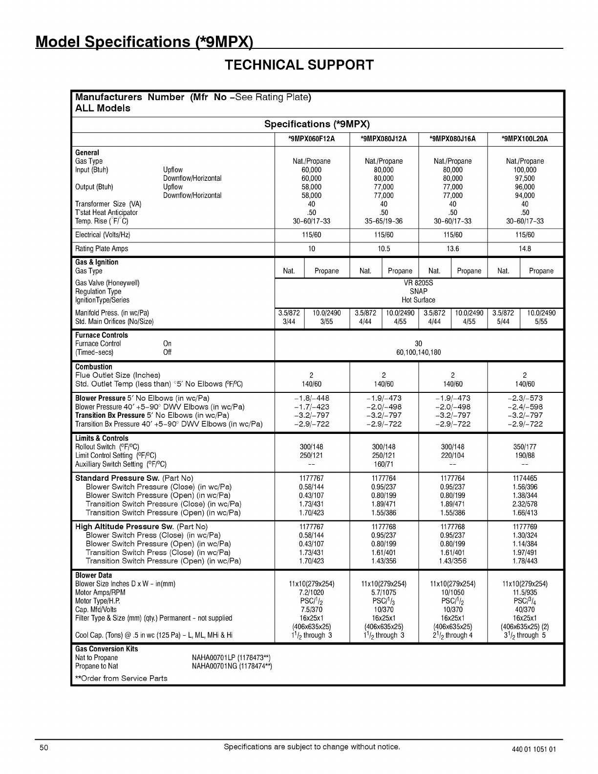
Model Specifications (*9MPX)
TECHNICAL SUPPORT
Manufacturers Number (Mfr No-See Rating Plate)
ALL Models
General
GasType
Input(Btuh)
Output(Btuh)
TransformerSize (VA)
Tstat Heat Anticipator
Temp.Rise (F/C)
Electrical(Volts/Hz)
RatingPlateAmps
Gas&Ignition
GasType
GasValve(Honeywell)
RegulationType
IgnitionType/Series
ManifoldPress, (inwc/Pa)
Std,MainOrifices(No/Size)
FurnaceControls
FurnaceControl On
(Timed-secs) Off
Combustion
Flue Outlet Size (Inches)
Upflow
Downflow/Horizontal
Upflow
Downflow/Horizontal
Specifications (*9MPX)
*9MPX060F12A *9MPX080J12A *9MPX080J16A *9MPX100L20A
Nat./Propane
60,000
60,000
58,000
58,000
40
.50
30-60/17-33
115!60
10
Nat, Propane
Nat./Propane
80,000
80,000
77,000
77,000
4O
.50
35-65/19-36
3.5/872 10.0!2490
3/44 3/55
115!60
10.5
Nat. Propane Nat.
VR 8205S
SNAP
Hot Surface
3.5/872 10.0/2490
4/44 4/55
Nat./Propane
80,000
80,000
77,000
77,000
4O
.50
30-60/17-33
115!60
13.6
Propane Nat,
Nat./Propane
100,000
97,500
96,000
94,000
40
.50
30-60/17-33
115!60
14.8
Propane
3.5/872 10.0/2490 3.5/872 10.0/2490
4/44 4/55 5/44 5/55
30
60,100,140,180
Std. Outlet Temp (less than) °5' No Elbows (°FPC)
BlowerPressure5' No Elbows (in wc/Pa)
BlowerPressure40' +5-90 ° DWV Elbows (in wc/Pa)
Transition Bx Pressure 5' No Elbows (in wc/Pa)
TransitionBxPressure 40' +5-90 ° DWV Elbows (in wc/Pa)
Limits & Controls
RolloutSwitch (°F/°C)
LimitControlSetting (°FPC)
AuxilliarySwitch Setting (°F/°C)
Standard Pressure Sw. (Part No)
Blower Switch Pressure (Close) (in wc/Pa)
Blower Switch Pressure (Open) (in wc/Pa)
Transition Switch Pressure (Close) (in wc/Pa)
Transition Switch Pressure (Open) (in wc/Pa)
High Altitude Pressure Sw. (Part No)
Blower Switch Press (Close) (in wc/Pa)
Blower Switch Pressure (Open) (in wc/Pa)
Transition Switch Press (Close) (in wc/Pa)
Transition Switch Pressure (Open) (in wc/Pa)
Blower Data
BlowerSize InchesDx W - in(mm)
MotorAmps/RPM
MotorType/H,E
Cap,Mfd/Volts
FilterType& Size (mm)(qty.)Permanent- not supplied
CoolCap. (Tons)@ .5 in wc (125 Pa) - L, ML, MHi & Hi
140/60
-1.8/-448
-1.7/-423
-3.2/-797
-2.9/-722
300/148
250/121
1177767
0,58/144
0,43/107
1,73/431
1.70/423
1177767
0,58/144
0,43/107
1,73/431
1.70/423
11x10(279x254)
7.2/1020
PSC!I_
7,5/370
16x25xl
(406x635x25)
11/2through3
140/60
-1.9/-473
-2.0/-498
-3.2/-797
-2.9/-722
300/148
250/121
160/71
1177764
0.95/237
0.80/199
1.89/471
1.55/386
1177768
0.95/237
0.80/199
1.61/401
1.43/356
11x10(279x254)
5.7/1075
PSC/1/3
10/370
16x25xl
(406x635x25)
11/2through3
140/60
-1.9/-473
-2.0/-498
-3.2/-797
-2.9/-722
300/148
220/104
1177764
0.95/237
0.80/199
1.89/471
1.55/386
1177768
0,95/237
0.80/199
1,61/401
1.43/356
11x10(279x254)
10/1050
PSC!I_
10/370
16x25xl
(406x635x25)
21/2through4
GasConversionKits
Natto Propane
Propaneto Nat
NAHA00701LP (1178473'_)
NAHA00701NG (1178474**)
**Order from Service Parts
140/60
-2.3/-573
-2.4/-598
-3.2/-797
-2.9/-722
350/177
190/88
1174465
1.56/396
1,38/344
2,32/578
1.66/413
1177769
1.30/324
1.14/384
1.97/491
1.78/443
11x10(279x254)
11,5/935
PSCf3/4
40/370
16x25xl
(406x635x25) (2)
31/2through 5
50 Specifications are subject to change without notice. 44001 105101
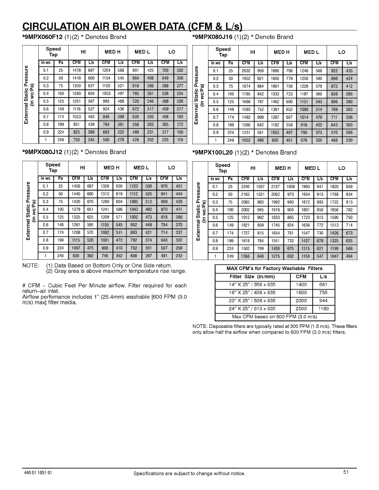
CIRCULATION AIR BLOWER DATA (CFM & L/s)
*9MPXO60F12 (1)(2) *Denotes Brand *9MPXO80J16 (1)(2) *Denote Brand
Speed HI MED H MED L LO
Tap
in wc Pa CFM L/s CFM L/s CFM L/s CFM L/s
0.1 25 1478 697 1204 568 901 425
0.2 50 1418 669 1154 545
0- _- 0.3 75 1350 637 1103 521
OIL
'_ _ 0.4 100 1280 604 1053 497
,- 0.5 125 1201 567 993 469
E 0.6 149 1116 527 924 436
0.7 174 1023 483
w 0.8 199 931 439
0.9 224
1 249
Speed HI MED H MED L LO
Tap
inwc Pa CFM Us CFM L/s CFM Us CFM L/s
0.1 25 2032 959 1690 798 1246 588
0.2 50 1952 921 1650 779 1250 590
_" 0.3 75 1874 884 1601 756 1226 579
'_ 0.4 100 1785 842 1533 723 1187 560
c 0.5 125 1688 797 1462 690
0.6 149 1593 752 1381 652
0.7 174 1482 699 1287 607
W 0.8 199 1360 642 1182 558
0.9 224 1231 581
1 249 iiiiiiiiiiiiii!ii_i_iiiiiiiiiiiiiili!iiiiiiiiiii_ii!_i!_i_i;i;i;iiiiiiiiiiiiiiiii;!_ii_iiiiiiiiiiiiiiiii iiiiiiiiiiiii_i_i_!ii!ii!ii!iiii!iliiiiiiiiiii_!iiiiiiiiiiiii
*9MPXO80J12 (1)(2) *Denotes Brand *9MPXIOOL20 (1)(2) *Denotes Brand
Speed HI MED H MED L LO
Tap
in wc Pa CFM L/s CFM L/s CFM L/s CFM L/s
"_ 0.1 25 1456 687 1326 626
0.2 50 1440 680 1312 619
_" 0.3 75 1420 670 1280 604
oQ.
'_ -_ 0.4 100 1379 651 1241 586
,- 0.5 125 1325 625 1209 571
0.6 149 1261 595
._ 0.7 174 1208 570
w 0.8 199
0.9 224
1 249
NOTE: (1) Data Based on Bottom Only or One Side return.
(2) Gray area is above maximum temperature rise range.
# CFM - Cubic Feet Per Minute airflow. Filter required for each
return-air inlet.
Airflow perfomance includes 1" (25.4mm) washable [600 FPM (3.0
m/s) max] filter media.
Speed HI MED H MED L LO
Tap
inwc Pa CFM L/s CFM Us CFM L/s CFM L/s
0.1 25 2240 1057 2137 1008 1993 941 1820 859
0.2 50 2163 1021 2062 973 1934 913 1768 834
_" 0.3 75 2083 983 1992 940 1872 883 1722 813
'_ 0.4 100 2002 945 1916 904 1801 850 1656 782
0.5 125 1912 902 1833 865 1723 813 1590 750
0.6 149 1821 859 1745 824 1636 772 1513 714
0.7 174 1727 815 1654 781 1547 730
W 0.8 199 1618 764 1551 732 iiiiiiiii!i!_!_iliiiiii!iiiiiiil;ii_i_iiiiiiiiiiiiii!ii!iiiiiiiili!i!_!_!ii!ii!ii!iiii!iiliiiiiiiiii_i_!ii!ii!ii!ii!i!i!i!i
0.9 224 1502 709
1 249 iiiiiiii;_i!ii;ii_!_i!i_ii!i_!i!i!iiiiiiiiiiii_ii;ii;ii;ii;ii;ii;ii;ii;iiiliiiiiiiiii;_i!iiiiii_i!_ililiiiii!iiiiiiiii_iiiiii_!i_ii!ii!ii!ii!iiiiiiiii_!_i!ii!ii!ii!ii!iiiiiiiiii;ii!ii!i_!_i!ii!ii:ii!iiiiiiiiiii_i_:!i:!i:!i:!i:!i:!i!!i
MAX CFM's for Factory Washable Filters
Filter Size (in/mm) CFM L/s
14" X 25" /356 x 635 1400 661
16" X 25" /406 x 635 1600 755
20" X 25" /508 x 635 2000 944
24"X25"/610x635 2500 1180
Max CFM based on 600 FPM (3.0 m/s)
NOTE: Dis )osable filters are typically rated at 300 FPM (1.5 m/s). These filters
only allow half the airflow when compared to 600 FPM (3.0 m/s) filters.
44001 105101 Specifications are subject to change without notice. 51
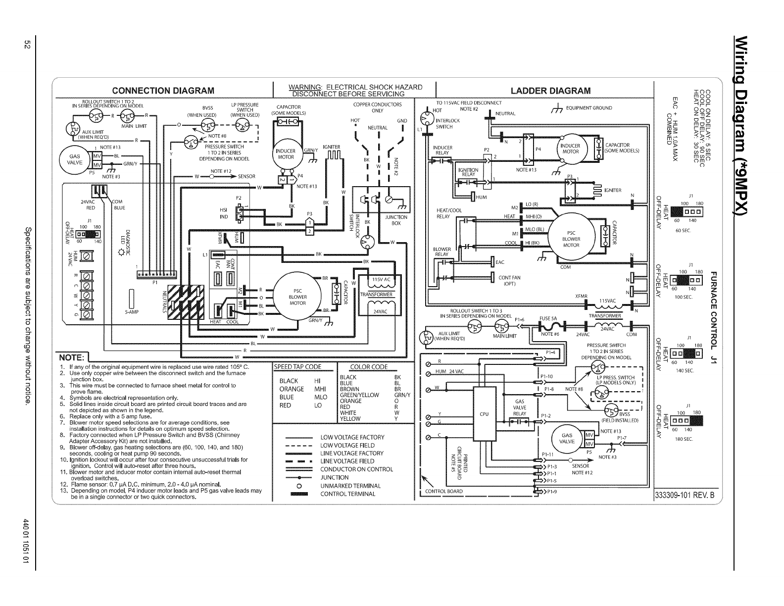
--W "R
1. If any of the original equipment wire is replaced use wire rated 105° C.
2. Use only copper wire between the disconnect switch and the furnace
junction box.
3. This wire must be connected to furnace sheet metal for control to
prove flame.
4. Symbols are electrical representation only.
5. Solid lines inside circuit board are printed circuit board traces and are
not depicted as shown in the legend.
6. Replace only with a 5 amp fuse.
7. Blower motor speed selections are for average conditions, see
installation instructions for details on optimum speed selection.
8. Factory connected when LP Pressure Switch and BVSS (Chimney
Adapter Accessory Kit) are not installed.
9. Blower off-delay, gas heating selections are (60, 100, 140, and 180)
seconds, cooling or heat pump 90 seconds,
10. Ignition lockout will occur after four consecutive unsuccessful trials for
ignition. Control will auto-reset after three hours.
1!, Blower motor and inducer motor contain internal auto-reset thermal
overload switches.
12, Flame sensor: 0.7 pA D.C. minimum, 2,0 - 4.0 pA nominal.
13. Depending on model, P4 inducer motor leads and P5 gas valve leads may
be in a single connector or two quick connectors,
SPEED TAP CODE
BLACK HI
ORANGE MHI
BLUE MLO
RED LO
0
m
COLOR CODE
BLACK BK
BLUE BL
BROWN BR
GREEN/YELLOW GRN/Y
ORANGE O
RED R
WHITE W
YELLOW Y
LOW VOLTAGE FACTORY
LOW VOLTAG EFIELD
LINE VOLTAGE FACTORY
LINE VOLTAGE FIELD
CONDUCTOR ON CONTROL
JUNCTION
UNMARKED TERMINAL
CONTROL TERMINAL
l LADDER DIAGRAM
TO 115VACFIELDDISCONNECT
NOTE#2 EQUIPMENTGROUND
HOT |NEUTRAL "/_
1 P3 1
IG_NITE R N
HEAT/ --
HEAT MHI (O) _
COOL_ _°wo_#L_ o
COM Ir----
CONTFAN N[_
(OPT)
XFMR N[_
ROLLOUTSWITCHI TO3
INSERIESDEPENDINGON MODEL .TRANSFORMER
/ _ NUM_VAC IP116
I
F,ELD,NSTAL ED
_> Pl-3 SENSOR
[CONTROL BOARD _>Pl=9
zoo
moo
_oo
9oo
o+_z
m_m
_m_
mw m
x om ©
©
Jl
O 100 180
_.._ "-4 60 140
60 SEC
J1
_31: 100 180
I-- _ 60 140 ;!_
_'_ lOBSEC _
o
--I
Of 100 180 r
-rl
r- 60 140
_'_ 140SEC
J1
C)m 100 180
___-4 60 140
180SEC
333309-101REV.B
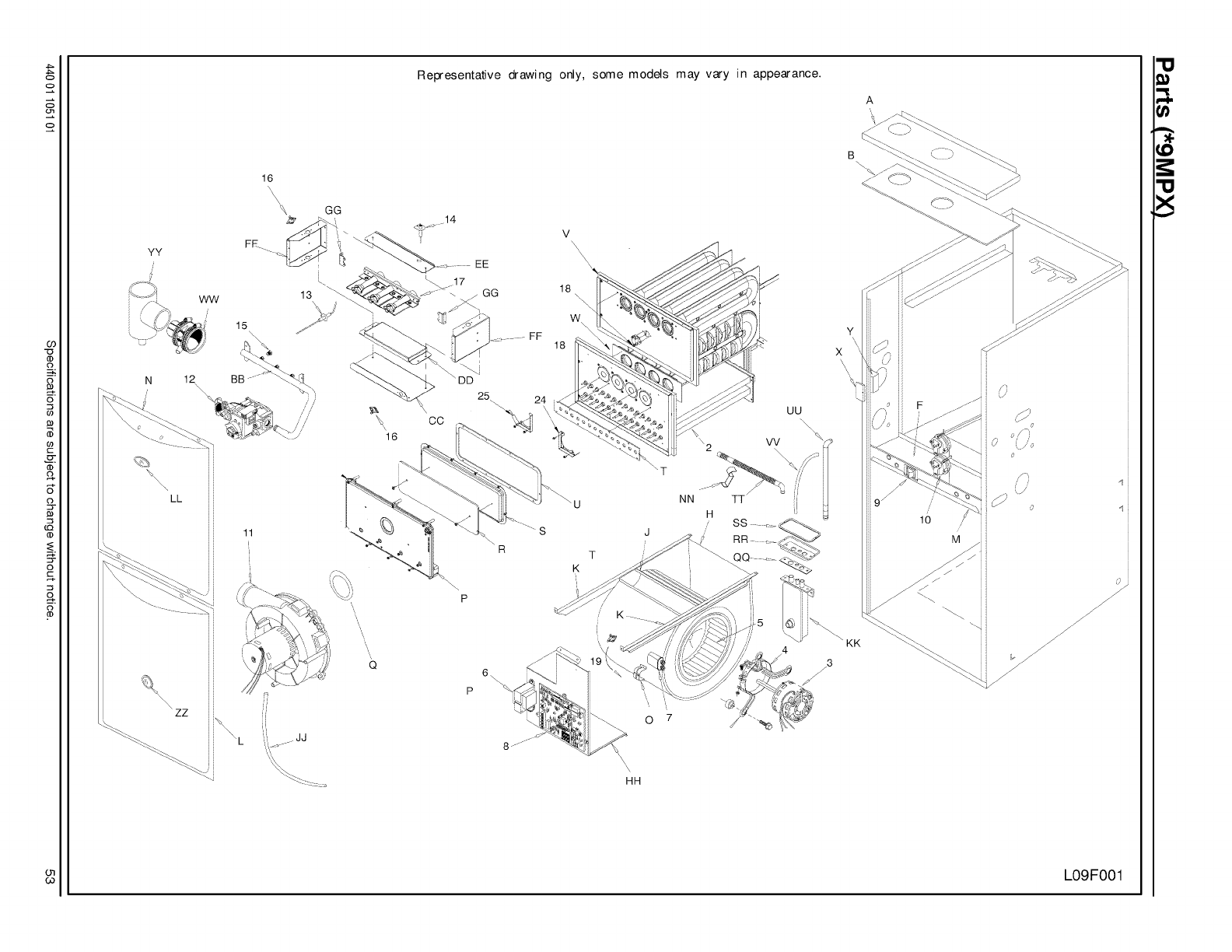
YY
ww
16
\\_, GG
FE......._'/:_"
13
15
N 12\
LL
11
\, zz
JJ
Representative drawing only, some models may vary in appearance.
14
EE
GG 18
W
18
UU
\\
p
HH
T
7
O
NN
H
TT
A
Y
x
\\\
lO
3
J
/
,t
d
L09F001
"U
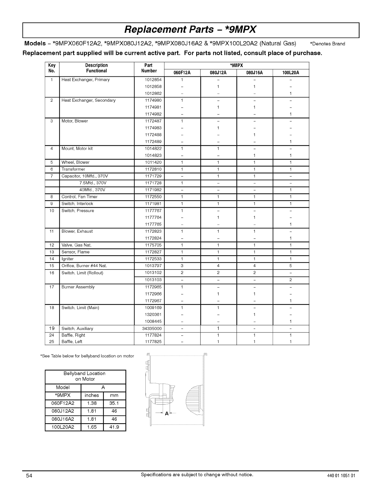
IReplacement Parts - *9MPX
Models -*9MPX060F12A2, *9MPX080J12A2, *9MPX080J16A2 &*9MPX100L20A2 (Natural Gas) *Denotes Brand
Replacement part supplied will be current active part. For parts not listed, consult place of purchase.
Key Description *9MPX
No. Functional 100L20A
080J 16A
1 Heat Exchanger, Primary
1
1
2 Heat Exchanger, Secondary
1
1
3 Motor, Blower
1
1
4 Mount, Motor kit
1 1
5 Wheel, Blower 1 1
6 Transformer 1 1
7 Capacitor, 10Mfd,, 370V 1
7.5Mfd,, 370V
40Mfd,, 370V 1
8 Control, Fan Timer 1 1
9 Switch, Interlock 1 1
10 Switch, Pressure
1
1
11 Blower, Exhaust 1
1
12 Valve, Gas Nat, 1 1
13 Sensor, Flame 1 1
14 Igniter 1 1
15 Orifice, Burner #44 Nat, 4 5
16 Switch, Limit (Rollout) 2
2
17 Burner Assembly
1
1
18 Switch, Limit (Main)
1
1
19 Switch, Auxiliary
24 Baffle, Right - 1 1
25 Baffle, Left - 1 1
Part
Number
1012854
1012858
1012862
1174980
1174981
1174982
1172487
1174983
1172488
1172489
1014822
1014823
1011420
1172810
1171729
1171728
1171982
1172550
1171981
1177767
1177764
1177765
1172823
1172824
1175705
1172827
1172533
1013797
1013102
1013103
1172965
1172966
1172967
1009169
1320361
1008445
34335000
1177824
1177825
060 F12A
1
1
1
1
1
1
1
1
1
1
1
1
1
1
3
2
1
1
080J12A
1
1
1
1
1
1
1
1
1
1
1
1
1
1
4
2
1
1
1
1
1
*See Table below for bellyband location on motor
Bellyband Location
on Motor
Model A
*9MPX inches mm
060F12A2 1.38 35.1
080J12A2 1.81 46
080J16A2 1.81 46
100L20A2 1.65 4t .9
54 Specifications are subject to change without notice. 440 01 105101
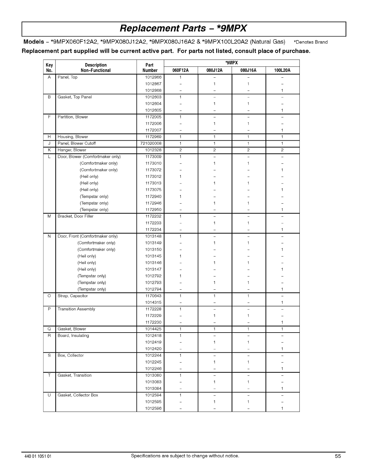
IReplacement Parts - *9MPX
Models -*9MPX060F12A2, *9MPX080J12A2, *9MPX080J16A2 &*9MPX100L20A2 (Natural Gas) *Denotes Brand
Replacement part supplied will be current active part. For parts not listed, consult place of purchase.
Key Description *9MPX
No. Non-Functional 100L20A060F12A
A Panel, Top 1
1
B Gasket, Top Panel 1
1
F Partition, Blower 1
1
H Housing, Blower 1 1
J Panel, Blower Cutoff 1 1
K Hanger, Blower 2 2
L 1
Door, Blower (Comfortmaker only)
(Comfortmaker only)
(Comfortmaker only)
(Heil only)
(Heil only)
(Heil only)
(Tempstar only)
(Tempstar only)
(Tempstar only)
Bracket, Door Filler
1
M 1
1
N 1
Door, Front (Comfortmaker only)
(Comfortmaker only)
(Comfortmaker only)
(Heil only)
(Heil only)
(Heil only)
(Tempstar only)
(Tempstar only)
(Tempstar only)
Strap, Capacitor
1
O 1
1
P Transition Assembly 1
1
Q Gasket, Blower 1 1
R Board, Insulating 1
1
S Box, Collector 1
1
T Gasket, Transition 1
1
U Gasket, Collector Box 1
1
Part
Number
1012866
1012867
1012868
1012603
1012604
1012605
1172005
1172006
1172007
1172969
721020008
1012328
1173009
1173010
1173072
1173012
1173013
1173075
1172940
1172946
1172950
1172232
1172233
1172234
1013148
1013149
1013150
1013145
1013146
1013147
1012792
1012793
1012794
1170643
1014315
1172228
1172229
1172230
1014425
1012418
1012419
1012420
1012244
1012245
1012246
1013080
1013083
1013084
1012594
1012595
1012596
080J 12A
1
1
1
1
1
2
1
1
1
1
1
1
1
1
1
1
1
1
1
1
080J16A
1
1
1
1
1
2
1
1
1
1
1
1
1
1
1
1
1
1
1
1
44001 105101 Specifications are subject to change without notice. 55
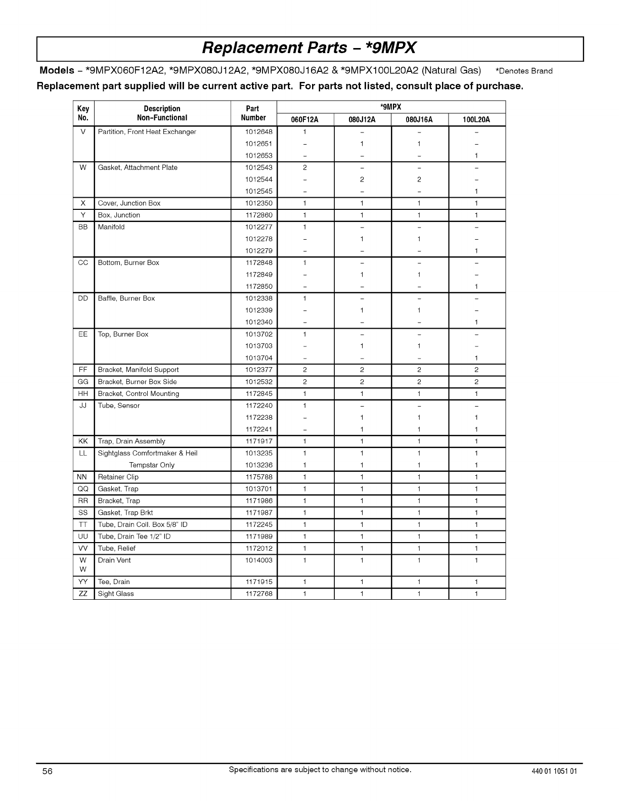
IReplacement Parts - *9MPX
Models -*9MPX060F12A2, *9MPX080J12A2, *9MPX080J16A2 &*9MPX100L20A2 (Natural Gas) *Denotes Brand
Replacement part supplied will be current active part. For parts not listed, consult place of purchase.
Key Description *9MPX
No. Non-Functional 060F12A 080J12A 080J16A 100L20A
V Partition, Front Heat Exchanger 1 - -
1 1 -
- 1
W Gasket, Attachment Plate 2 - -
2 2 -
- 1
X Cover, Junction Box 1 1 1 1
Y Box, Junction 1 1 1 1
BB Manifold 1 - -
1 1 -
- 1
CC Bottom, Burner Box 1 - -
1 1 -
- 1
DD Baffle, Burner Box 1 - -
1 1 -
- 1
EE Top, Burner Box 1 - -
1 1 -
- 1
FF Bracket, Manifold Support 2 2 2 2
GG Bracket, Burner Box Side 2 2 2 2
HH Bracket, Control Mounting 1 1 1 1
JJ Tube, Sensor 1 - -
1 1 1
1 1 1
KK Trap, Drain Assembly 1 1 1 1
LL Sightglass Comfortmaker & Heil 1 1 1 1
Tempstar Only 1 1 1 1
NN Retainer Clip 1 1 1 1
QQ Gasket, Trap 1 1 1 1
RR Bracket, Trap 1 1 1 1
SS Gasket, Trap Brkt 1 1 1 1
TT Tube, Drain Coll. Box 5/8" ID 1 1 1 1
UU Tube, Drain Tee 1/2" ID 1 1 1 1
VV Tube, Relief 1 1 1 1
W Drain Vent 1 1 1 1
W
YY Tee, Drain 1171915 1 1 1 1
ZZ Sight Glass 1172768 1 1 1 1
Part
Number
1012648
1012651
1012653
1012543
1012544
1012545
1012350
1172860
1012277
1012278
1012279
1172848
1172849
1172850
1012338
1012339
1012340
1013702
1013703
1013704
1012377
1012532
1172845
1172240
1172238
1172241
1171917
1013235
1013236
1175788
1013701
1171986
1171987
1172245
1171989
1172012
1014003
56 Specifications are subject to change without notice. 440 01 105101
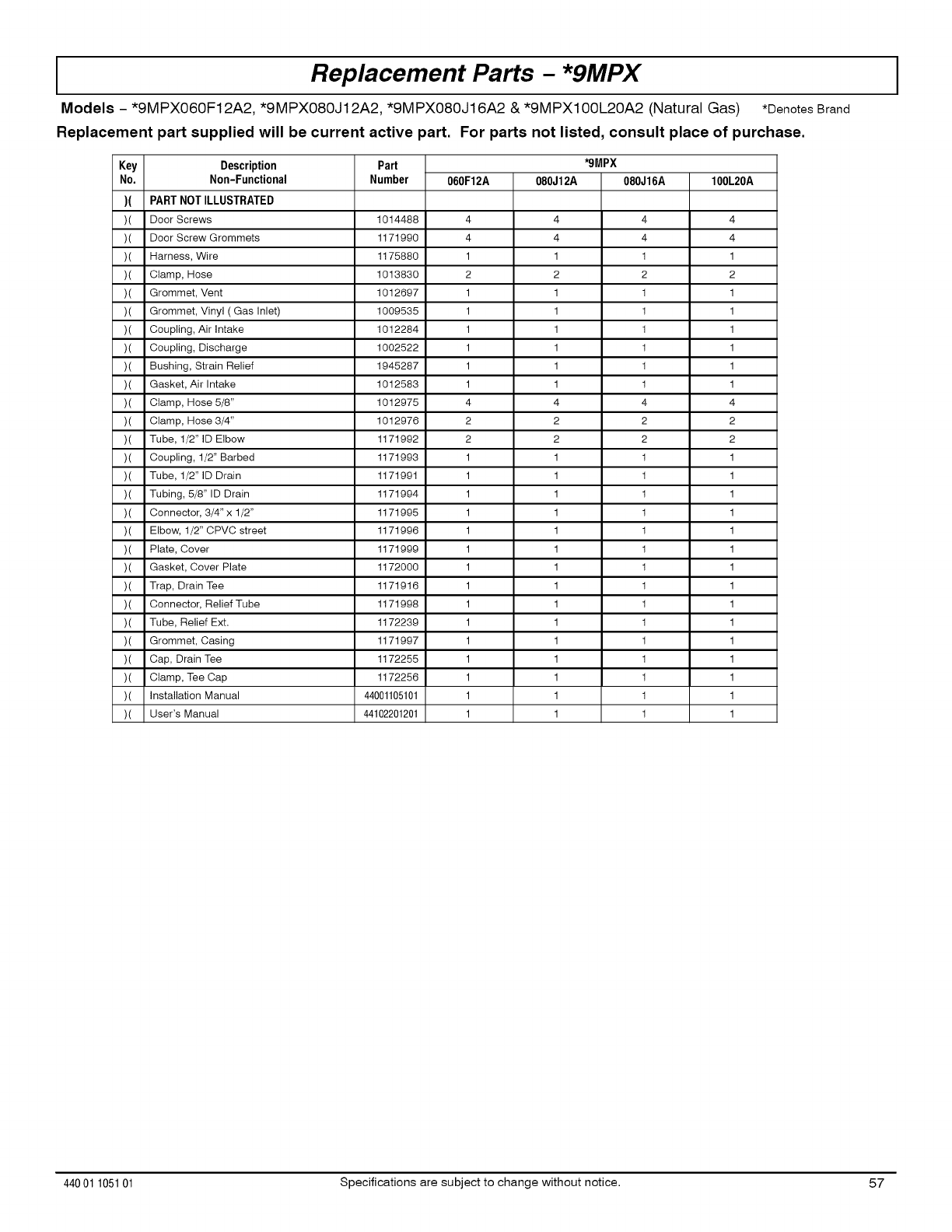
IReplacement Parts - *9MPX
Models -*9MPX060F12A2, *9MPX080J12A2, *9MPX080J16A2 &*9MPX100L20A2 (Natural Gas) *Denotes Brand
Replacement part supplied will be current active part. For parts not listed, consult place of purchase.
Part *9MPX
Number 060F12A 080J12A 080J16A 100L20A
Key Description
No. Non-Functional
)( PART NOT ILLUSTRATED
)( Door Screws
)( Door Screw Grommets
)( Harness, Wire
)( Clamp, Hose
)( Grommet, Vent
)( Grommet, Vinyl ( Gas Inlet)
)( Coupling, Air Intake
)( Coupling, Discharge
)( Bushing, Strain Relief
)( Gasket, Air Intake
)( Clamp, Hose 5/8"
)( Clamp, Hose 3/4"
)( Tube, 1/2" ID Elbow
)( Coupling, 1/2" Barbed
)( Tube, 1/2" ID Drain
)( Tubing, 5/8" ID Drain
)( Connector, 3/4" x 1/2"
)( Elbow, 1/2" CPVC street
)( Plate, Cover
)( Gasket, Cover Plate
)( Trap, Drain Tee
)( Connector, Relief Tube
)(
)(
)(
)(
)(
)(
1014488 4 4 4 4
1171990 4 4 4 4
1175880 1 1 1 1
1013830 2 2 2 2
1012697 1 1 1 1
1009535 1 1 1 1
1012284 1 1 1 1
1002522 1 1 1 1
1945287 1 1 1 1
1012583 1 1 1 1
1012975 4 4 4 4
1012976 2 2 2 2
1171992 2 2 2 2
1171993 1 1 1 1
1171991 1 1 1 1
1171994 1 1 1 1
1171995 1 1 1 1
1171996 1 1 1 1
1171999 1 1 1 1
1172000 1 1 1 1
1171916 1 1 1 1
1171998 1 1 1 1
Tube, Relief Ext. 1172239 1 1 1 1
Grommet, Casing 1171997 1 1 1 1
Cap, Drain Tee 1172255 1 1 1 1
Clamp, Tee Cap 1172256 1 1 1 1
Installation Manual 44001105101 1 1 1 1
User's Manual 44102201201 1 1 1 1
44001 105101 Specifications are subject to change without notice. 57

THIS PAGE LEFT
BLANK
INTENTIONALLY
58 Specifications are subject to change without notice. 440 01 105101
