ID TECH VP5300 VP5300 User Manual
ID TECH VP5300
UserManual.wiki
>
ID TECH
>
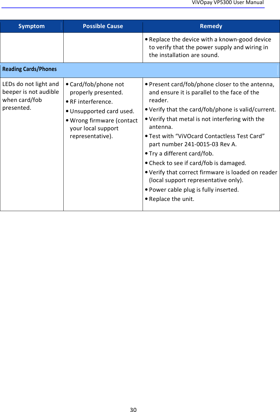
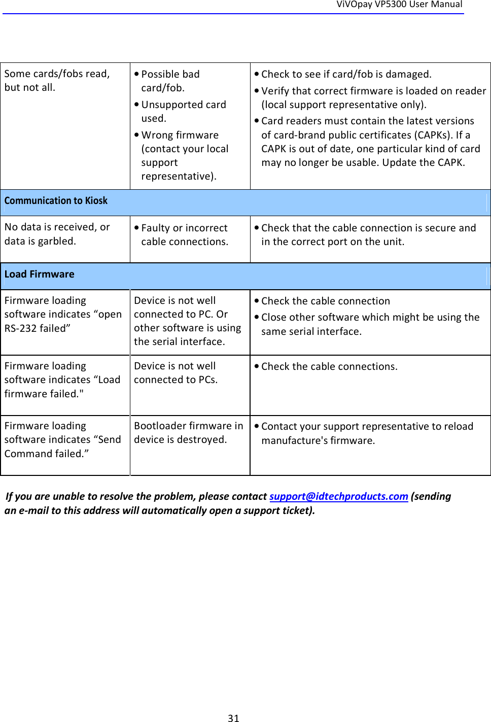
VP5300 User Manual
User manual
Navigation menu
Upload a User Manual
Namespaces
Wiki Guide
HTML
PDF
Info
Views
User Manual
Discussion / Help
Navigation