ID Teck Co FGR006 Fingerprint & Proximity Reader User Manual FGR006 English021102
ID-Teck Co Ltd Fingerprint & Proximity Reader FGR006 English021102
User Manual
FGR006 Proximity & Fingerprint Reader
20021102 - 1 - User’s Manual
USER’s MANUAL
Fingerprint & Proximity Reader

FGR006 Proximity & Fingerprint Reader
20021102 - 2 - User’s Manual
Contents
1. Important Safety Precautions..................... 3
2. Introduction............................................. 3
3. Specification............................................ 4
4. Unpacking............................................... 4
5. Layout..................................................... 5
6. Installation............................................... 5
7. Wire Color Table....................................... 6
8. System wiring for Typical Application.......... 7
9. Wiring for Networking................................ 9
10. Operation..............................................10
11. FCC Ragistration Information…………………11
12. Warranty and Service............................. 12

FGR006 Proximity & Fingerprint Reader
20021102 - 3 - User’s Manual
1. Important Safety Precautions
The following safety precautions must be taken to reduce the risk of fire, electrical
shock, and injury to persons. In addition, the following safety guides should also be
followed:
1. FULLY read and understand all instructions and follow them completely.
2. FOLLOW all warnings and instructions marked on the product.
3. Do NOT use liquid or aerosol cleaners. Use a damp cloth for cleaning. If necessary,
use mild soap.
4. Do NOT use this product near water.
5. To operate this product, use the type of power source indicated ONLY. If you are not
sure of the type of power supplied to your installation site, consult your dealer or local
power company.
6. NEVER disassemble this product by yourself; take the unit to a qualified service
center whenever service or repair is required. Opening or removing the covers may
expose you to dangerous voltages or other risks. Also, incorrect reassembly can
cause electric shock when the unit is subsequently used.
8. UNPLUG this product from the Direct Current (DC) power source and refer to
qualified service personnel under these conditions:
a. When the power supply cord or plug is damaged or frayed.
b. If liquid has been spilled on the product.
c. If the product does not operate normally after following the operating
instructions in this manual.
Adjust only those controls that are covered by the operating instructions in this
manual. Improper adjustment of other controls that are not covered by this
manual may damage the unit and will often require extensive work by a qualified
technician to restore normal operation.
d. If the product exhibits a distinct change in performance.
2. Introduction
The STAR FGR006 proximity & fingerprint reader utilizes a highly advanced
technology with a 32-bit and two 8-bit microprocessor to meet the market requirement
for robust access control systems. The unit is designed to be flexible and reliable as
well as to provide the ultimate in biometric security at a reasonable cost. This
user-friendly device allows you to register up to 720 fingerprint IDs(optionally,
2,000/4,500). With a built-in 4" RF reader and a sophisticated biometric fingerprint
analyzer, the FGR006 offers two levels of ID verification. The easy-to-install unit
provides the RS232 and RS422/485 communication ports for networking. The two LED
indicator lights inform you of the system’s operating status at real time. The field
proven FGR006 has made real what had been thought, until recently, only to be
possible in science fiction.

FGR006 Proximity & Fingerprint Reader
20021102 - 4 - User’s Manual
3. Specification
CPU One 32-bit and two 8-bit Microprocessors
Memory Program memory(64 Kb ROM)
Power 12VDC/ 350mA max.
Card Read Range Up to 4"(10cm) with the IDC170 cards
Card Holders 720(optional 2,000/4,500)
Reader ports/Data format 1 internal port/ Wiegand or ABA Track II
Communication One RS-232 port and one RS-422 port/ 4800,
9600(default) and 19200bps, Address selectable(0 to 255)
Card data format 26-bit Wiegand or ABA Track II
Reset Power on reset & Watchdog timer
LED 2 LEDs(red, green)
Environmental range -15°C to +40°C, 10% to 90% Humidity
Weight 230g
Dimensions 66×129×50.6 (mm)
Color Gray & Dark gray
Material Polycarbonate
4. Unpacking
Your package contains the following items..
Main unit Bezel User’s manual
Figure 1. Identifying items
FGR006 Proximity & Fingerprint Reader
20021102 - 5 - User’s Manual
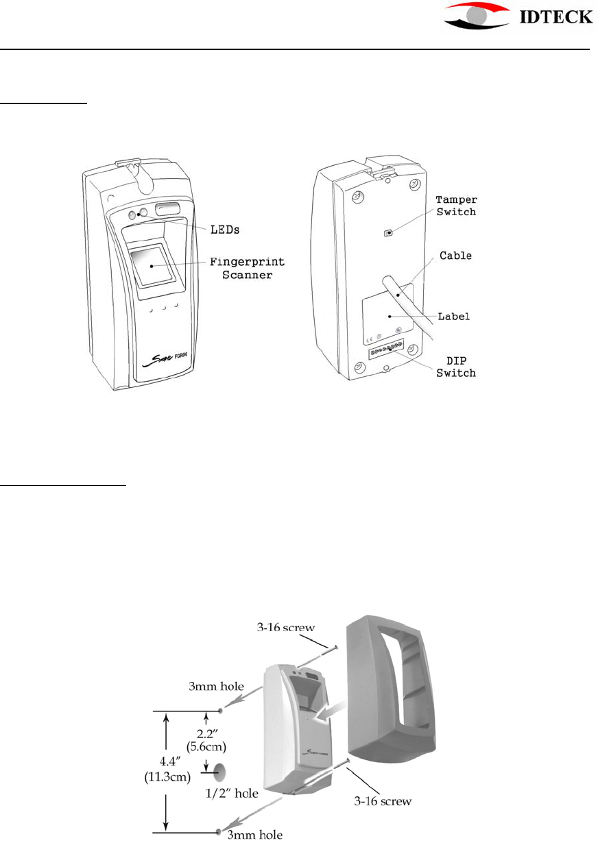
5. Layout
The following illustration shows the FGR006’s main elements.
Figure 2. Layout
6. Installation
1) Drill two 3mm holes 4.45”(113mm) apart in vertical and one 1/2” hole for the
controller cable 2.2”(56mm) apart from the top hole.
2) Put the reader cable into the center hole and install the controller module with two
3-20 screws.
3) Put bezel onto the reader module, and then push it until you hear the locking sound.
Figure 3. Installation

FGR006 Proximity & Fingerprint Reader
20021102 - 6 - User’s Manual
7. Wire Color Table
I/O NAME SIGNAL NAME COLOR CODED
POWER
Main Power (+12V) +12V Red wire
Power Ground GND Black wire
OUTPUT
Tamper TTL(Low active) Purple wire
Alarm Error(Low active) Orange wire
WIEGAND OUTPUT
Wiegand Data-0 DATA-0 Green wire
Wiegand Data-1 DATA-1 White wire
ABA Track II OUTPUT
Data Data Green wire
Clock Clock White wire
Card Present CP Orange wire
RS232 INTERFACE
RS232-TX TXD Yellow wire
RS232-RX RXD Grey wire
RS422 INTERFACE
RS422-TX(-) TXD(-) Yellow wire
RS422-TX(+) TXD(+) Grey wire
RS422-RX(-) RXD(-) Blue wire
RS422-RX(+) RXD(+) Brown wire
RS485 INTERFACE
RS485-A A Grey wire
RS485-B B Yellow wire

FGR006 Proximity & Fingerprint Reader
20021102 - 7 - User’s Manual
8. System Wiring for Typical Application
8.1 Power Connection
- Connect 12V power to Red wire
- Connect Power GND (-) wire of DC 12V to Black wire
8.2 RS-232 Communication Port Connection
A 9-pin connector (COM Port, female) is required for the serial communication
RS-232 between Main Unit and Personal Computer.
- Connect RS232-TX, Yellow wire of Main Unit to pin number 2 of
9-pin connector.
- Connect RS232-RX, Gray wire of Main Unit to pin number 3 of
9-pin connector.
- Connect GND, black wire of Main Unit to pin number 5 of 9-pin connector.
- Plug in 9-pin connector to COM1 or COM2 Port of Personal Computer.
- Install and run Application Software.
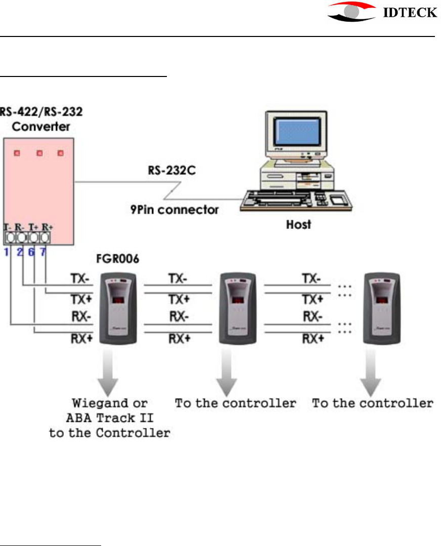
8.3 RS-422 Communication Port Connection
RS-422/RS-232 converter is required to connect serial communication RS-422
between Main Unit and Personal Computer.
- Connect RS422-TX(-), Yellow wire of Main unit to RX(-) port of converter.
- Connect RS422-TX(+), Gray wire of Main unit to RX(+) port of converter.
- Connect RS422-RX(-), Blue wire of Main unit to TX(-) port of converter.
- Connect RS422-RX(+), Brown wire of Main unit to TX(+) port of converter.
- Plug in RS232 9-pin connector of RS-422/RS-232 converter to COM1 or COM2
Port of Personal Computer.
- Install and run Application Software.
8.4 RS-485 Communication Port Connection
RS-485/RS-232 converter is required to connect serial communication RS-485
between Main Unit and Personal Computer.
- Connect RS485-A, Gray wire of Main unit to RX(-) port of converter.
- Connect RS485-B, Yellow wire of Main unit to RX(+) port of converter.
- Plug in RS232 9-pin connector of RS-485/RS-232 converter to COM1 or COM2
Port of Personal Computer.
- Install and run Application Software.
8.5 Card ID Line-Main controller Connection
Door controller uses Wiegand or ABA Track II format signals from the FGR006.
7.5.1 Wiegand Input Controller.
- Connect Wiegand Data-0, Green wire of Main unit to D-0 input terminal of the
controller.
- Connect Wiegand Data-1, White wire of Main unit to D-1 input terminal of the

FGR006 Proximity & Fingerprint Reader
20021102 - 8 - User’s Manual
controller.
7.5.2 ABA Track II Input Controller.
- Connect Data, Green wire of Main unit to Data input terminal of the controller.
- Connect Clock, White wire of Main unit to Clock input terminal of the controller.
- Connect Card Present, Orange wire of Main unit to CP input terminal of the
controller.
8.6 Tamper output-Main controller Connection
The Purple wire of the cable will be High logical state when the unit is installed
properly and powered on. And its logical state turns to Low when the Tact Switch on
the rear side of the unit is released, indicating the unit is detached from the wall.
- Connect Tamper, Purple wire of Main unit to TTL input terminal of the controller.
FGR006 Proximity & Fingerprint Reader
20021102 - 9 - User’s Manual
9. Wiring for Networking
Figure 4. Networking
10. Operation
When power is first applied to the reader, it starts its operation with a brief buzzer sound, lighting
the red LED. And the fingerprint scanner and the green LED flashes. Finally, it beeps four times
before it gets into a READY status mode where you may present an RF card or a tag to the
reader or communicate via RS232/RS422 connection, if connected, for managing ID data, for
instance, downloading fingerprints.

FGR006 Proximity & Fingerprint Reader
20021102 - 10 - User’s Manual
10.1 Presenting the Card
Present an RF card to the reader and move it slowly toward the face of the reader until
the green LED flashes with a beep. This is the point at which the card is read and the ID
data is compared to the ones stored.
10.2 Scanning the Fingerprint
If the ID read is found to be a registered one, the unit waits for a fingerprint to be
scanned. Put the finger corresponding to the ID on the scanner while it is flashing.
As the scanning is complete, the unit collates the image with one stored as the ID’s and
decides whether to send the ID to the controller or not.
10.3 Back to the READY status mode
After sending the ID data, when a valid card ID and fingerprint is presented, to the
controller, the unit goes back to the READY status mode for next reading.
Or in case of a void fingerprint input, the unit will beep two times and go back to the READY
status mode.
If the card or tag, presented to the reader, is found not to be registered before, the FGR006
beeps three times and goes back to the READY status mode for next reading.
10.4 Registering IDs
Registering and managing IDs need an application software, therefore, if you use
RS 422 or RS 485 connection, please set the unit’s address first. You can choose
one among the numbers 0 to 255 with the DIP switch seen on the rear side of the
FGR006(see Figure 2). Be aware that you should avoid addresses occupied by
controllers or other units on the same network line.
The factory set address ‘0’ is shown in Figure 5.
Figure 5. Factory set address, ‘0’
The DIP switch expresses an address number in the binary system. The switch
No.8 corresponds to the address’ MSB and the switch No. 1, the LSB. Note that a
switched-on bit becomes ‘0’, not ‘1’.

FGR006 Proximity & Fingerprint Reader
20021102 - 11 - User’s Manual
The unit has an operation mode for registering IDs. The mode can be selected
using the application software for the FGR006. For mode selection, please refer to
the application software manual.
In the ID REGISTRATION mode, present an RF card to the reader, and then put
your finger on the scanner while it is flashing. It scans your fingerprint twice to
obtain slightly different images, therefore, you need to lift and put the finger again
briefly before the second flash starts. Repeat the procedure for further
registrations.
You can also transmit the IDs with its fingerprints to other units, using the
software. For the details, please refer to the software manual.
Don’t forget to resume the READY status mode before completing registrations.
11. FCC REGISTRATION INFORMATION
FCC REQUIREMENTS PART 15
Caution: Any changes or modifications in construction of this device which are not expressly approved
by the responsible for compliance could void the user's authority to operate the equipment.
NOTE: This device complies with Part 15 of the FCC Rules.
Operation is subject to the following two conditions;
1. This device may not cause harmful interface, and
2. This device must accept any interference received, including interference that may cause undesired
operation.
This equipment has been tested and found to comply with the limits for a Class A Digital Device,
pursuant to Part 15 of the FCC Rules. These limits are designed to this equipment generates, uses, and
can radiate radio frequency energy and, if not installed and used in accordance with the instructions,
may cause harmful interference to radio communications.
However, there is no guarantee that interference will not occur in a particular installation. If this
equipment does cause harmful interference to radio or television reception, which can be determined
by turning the radio or television off and on, the user is encouraged to try to correct interference by one
or more of the following measures.
1. Reorient or relocate the receiving antenna.
2. Increase the separation between the equipment and receiver.
3. Connect the equipment into an outlet on another circuit.
4. Consult the dealer or an experienced radio/TV technician for help.

FGR006 Proximity & Fingerprint Reader
20021102 - 12 - User’s Manual
12. Warranty and Service
The STAR FGR006 warranty is 2 years from the shipped date; returns must have an
RMA (Return Material Authorization) number. The customer is to provide a description
of the specific problem. The customer is to include serial numbers, formats, and model
numbers with the items to be returned.
Contact Technical Support
In the United states
RF LOGICS Inc. Service Center
3026 Scott Blvd.,
SANTA CLARA, CA95054
Tel.: (408)980-0001
Fax.: (408)980-8060
E-mail: rflogics@rflogics.com
Web-site: www.rflogics.com
Outside of the United states
ID TECK CO., LTD. Service Center
5F Ace Techno Tower Bldg.,
684-1 Deungchon-dong, Gangsuh-gu,
SEOUL 157-030, KOREA
Tel. : +82(2) 659-0055
Fax.: +82(2) 659-0086
E-mail: webmaster@idteck.com
Web-site: www.idteck.com
NOTE : Damage occurring during shipment is deemed the responsibility of the carrier,
and claims should be made directly to the carrier.