ID Teck Co PROX10H LOXURY-I User Manual
ID-Teck Co Ltd LOXURY-I Users Manual
Users Manual
User Manual
PROX10/10H
Proximity Reader

2
User Manual
Table of Contents
1. SAFETY INFORMATION ...................................................................... 3
2. PRODUCT INTRODUCTION .................................................................. 5
3. IDENTIFYING SUPPLIED PARTS ............................................................ 5
4. PRODUCT SPECIFICATION .................................................................. 6
5. PRODUCT INSTALLATION ................................................................... 7
6. WIRE COLOR TABLE ......................................................................... 8
7. WIRING DIAGRAM ............................................................................ 8
8. OPERATIONS .................................................................................. 9
9. FCC REGISTRATION INFORMATION ..................................................... 10
10. PRODUCT MANUAL DOWNLOAD INFORMATION .................................... 11

3
User Manual
1. SAFETY INFORMATION
This caution is for safety and preventing damage of property
Please read these instructions and follow them.
1) Acquaint yourself with all instructions thoroughly.
2) Heed all warnings and follow the instruction on the product.
Keep the instruction in a conspicuous place so administrator can see it always.
Power
supply
and
installation
Power Supply must be DC 12V.
- Higher voltage might cause electric shock,
fire and damage on the product.
Do not install the unit in humid, dusty, or sooty locations.
- Doing so may cause fire or electric shock. .
Do not install the unit where motor runs always.
- Doing so may cause malfunction of the unit.
Keep out of direct sunlight and heat radiation sources.
- It may cause fire.
If this product fails to operate normally, contact the engineer.
Never disassemble or modify this product in any way.
- Doing so may cause electric shock and fire.
Remove the power plug from the outlet when dealing with the unit.
Do not touch the unit with the device like driver in hand.
- Doing so may cause fire and damage on the device.

4
User Manual
When malfunction is caused by improper handling,
service center can charge cost
Operation
and
maintenance
When cleaning, do not spray water directly onto parts of the
product nor benzene, thinner.
- Doing so may cause fire or electric shock or damage
on the unit.
Do not randomly change the wiring installed by engineer
or expert.
- Doing so may cause fire or malfunction or damage of the unit.
Do not let the unit be touched by person expect administrator
for unusual purpose of using.
- Doing so may cause malfunction
Etc.
Never disassemble or modify this product in any way.
- Contact the nearest service center when repair is needed.
- This may cause electric shock or fire.
Keep the product out of spray or combustible substances.
- Doing so may cause explosion or fire
Damage
requiring
repair
Contact service center in following circumstances.
- When liquid has been spilled or objects have fallen
into the apparatus.
- When the apparatus has been exposed to rain or moisture.
- When the apparatus does not operate normally.
- When there has been apparent change in operating
of the apparatus.
- When the apparatus has been dropped or the external case
has been damaged.
5
User Manual
2. PRODUCT INTRODUCTION
PROX10 / PROX10H have sophisticated design as well as maximum recognition
distance of 4 inch. This proximity reader can be easily attached to a metal or
doorframe or the wall. Featured by the epoxy adhesion, PROX10 /PROX10H
have high level of weather-proofing in any challenging weather conditions.
This model contains red and blue inside and Piezo buzzer guarantees accurate
and reliable system operation.
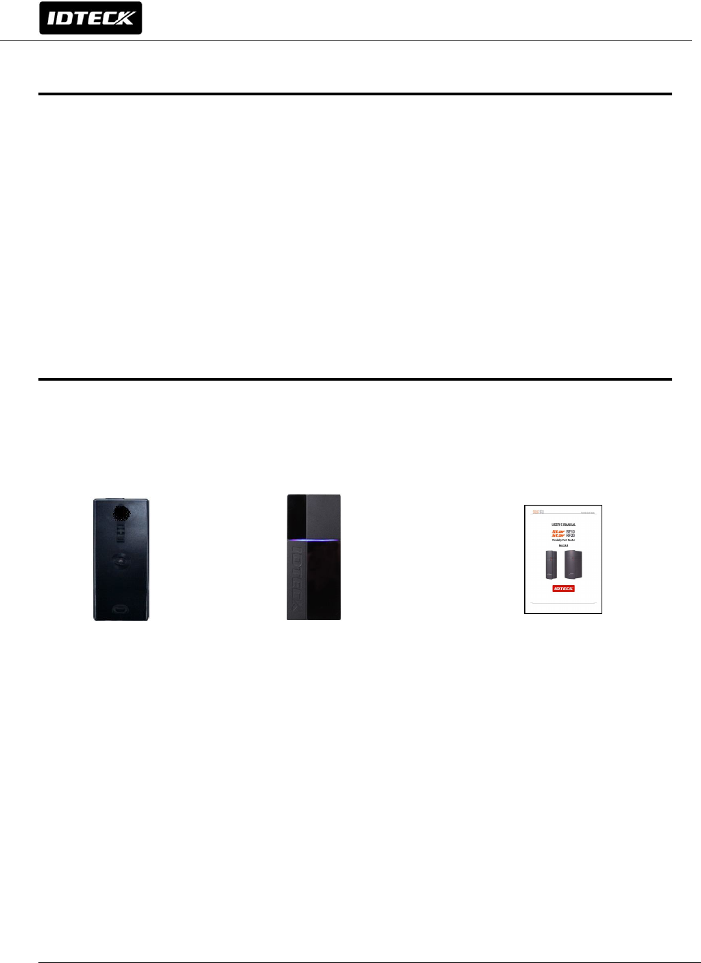
3. IDENTIFYING SUPPLIED PARTS
Please unpack and check the contents of the box.
Reader Module Bezel Quick Installation Guide
(1 ea) (1 ea) (1 copy)
6
User Manual
4. PRODUCT SPECIFICATION
Recognition distance /time 4"(10cm) / 30ms
Power/Current DC 12V, Max. 150mA
Output 26 bit Wiegand, 34bit Wiegand, RS232C
External buzzer control input Low Active, DC 0 ~ 12V, Max. 50 mA
External LED control input Low Active Low Active, DC 0 ~ 12V, Max. 50 mA
LED/buzzer 2 Color LED(Red/Blue) / Piezo Buzzer
Color Dark Pearl Gray
Operating temperature/humidity
14℉ ~ 140℉(-10℃ ~ +60℃),
10~90%(Humidity)
Size(WxHxD)
1.92" x 4.33" x 0.85"(49x110x21.5mm)
PROX10 and PROX10H are the same size.
Weight 0.26lb(120g)
7
User Manual
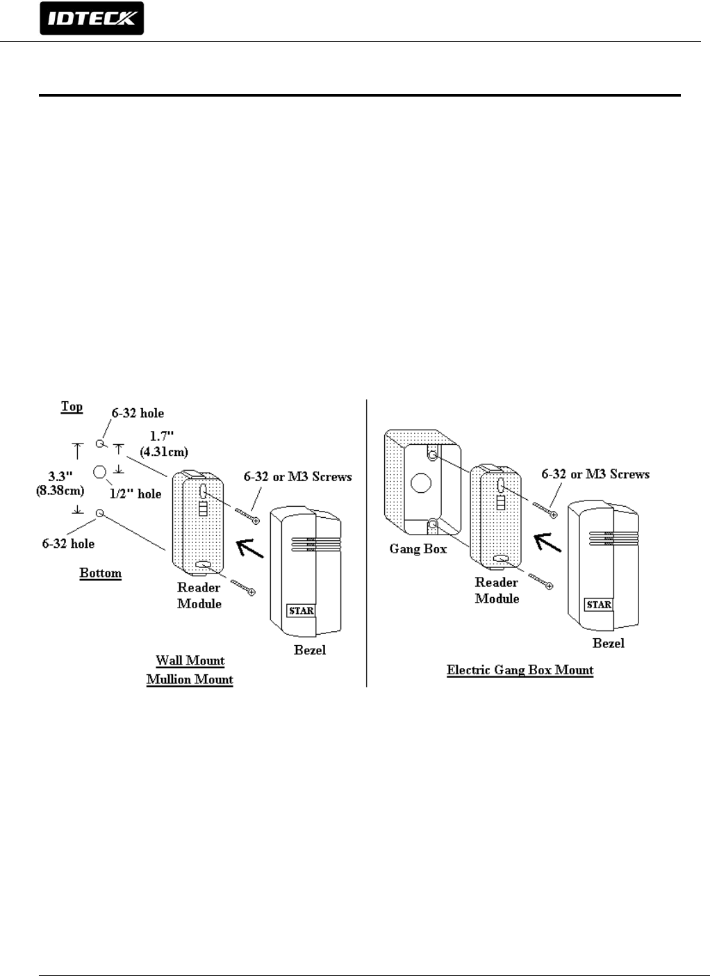
5. PRODUCT INSTALLATION
5-1. Inserting into doorframe / Attaching to wall
The distance between two 6-32/M3 holes which are located vertically is
3.3"(8.38cm). One 1/2" hole between them is for cable from the reader and has
1.7"(4.31cm) of distance from upper hole. (If it has been attached already, you
can skip this part)
5-2. Insert the reader cable to the hole in the middle and fix reader module
with two 6-32/M3 screws.
5-3. put the reader module in Bezel and push it until it clicked shut.
8
User Manual
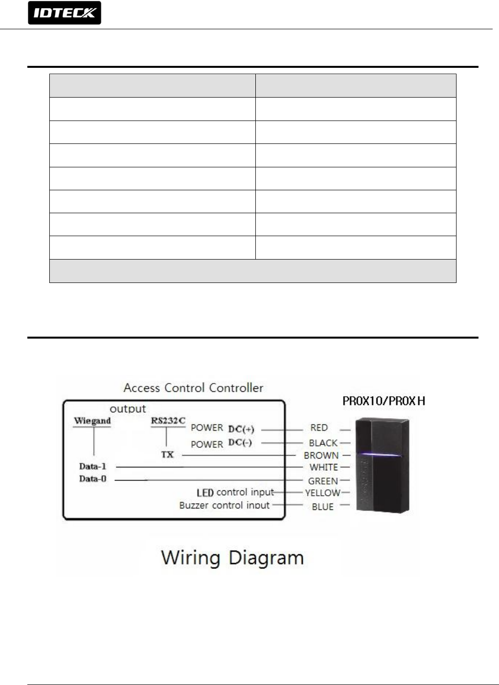
6. WIRE COLOR TABLE
7. WIRING DIAGRAM
Signal COLOR
Main Power (+12V) Red
Power Ground (GND) Black
Wiegand Data 0 Out Green
Wiegand Data 1 Out White
Buzzer Control In Blue
LED Control In Yellow
RS232C (TX) Brown
* Please cut out tail connector before installation.

9
User Manual
8. OPERATIONS
8-1. When power is applied to the reader, buzzer that indicates initialization is
generated. And the Blue LED is lit once the initialization is completed. And the
reader becomes standby mode.
8-2. Put the card near the reader until LED light changes from blue to red and
buzzer is generated. Reader sends the data to controller and becomes standby
mode for following card reading.
8-3. LED Control
Color of LED can be changed by connecting LED control input(Yellow wire) to
GND. It becomes standby mode with red LED is on. If card is scanned, LED
light changes from red to blue. And then it comes back to red for following
card reading.
8-4. Buzzer control;
Normally reader makes buzzer sound only once when card is scanned. Both
authorized case and unauthorized case make buzzer sound once. However
buzzer sound can be multiple if buzzer control input (blue wire) is connected
to GND. It’s applied to unauthorized case only. When buzzer control wire is
connected to GND, it keeps making buzzer sound.

10
User Manual
9. FCC REGISTRATION INFORMATION
FCC REQUIREMENTS PART 15
Caution: Any changes or modifications in construction of this device which are not expressly
approved by the responsible for compliance could void the user's authority to operate the
equipment.
NOTE: This device complies with Part 15 of the FCC Rules.
Operation is subject to the following two conditions;
1. This device may not cause harmful interface, and
2. This device must accept any interference received, including interference that may cause
undesired operation.
This equipment has been tested and found to comply with the limits for a Class B Digital Device,
pursuant to Part 15 of the FCC Rules. These limits are designed to this equipment generates,
uses, and can radiate radio frequency energy and, if not installed and used in accordance with
the instructions, may cause harmful interference to radio communications.
However, there is no guarantee that interference will not occur in a particular installation. If
this equipment does cause harmful interference to radio or television reception, which can be
determined by turning the radio or television off and on, the user is encouraged to try to
correct interference by one or more of the following measures.
1. Reorient or relocate the receiving antenna.
2. Increase the separation between the equipment and receiver.
3. Connect the equipment into an outlet on another circuit.
4. Consult the dealer or an experienced radio/TV technician for help.

11
User Manual
10. PRODUCT MANUAL DOWNLOAD INFORMATION
This Quick Installation Guide is a manual to provide product’s basic installation information only. If you
need all the information of the product, please download detailed manual following the steps specified
below.
For registered users of our homepage
1. Visit IDTECK’s homepage (www.idteck.com).
2. Click the Sign in button at the top of the homepage and log in using your registered
ID and P/W.
3. Click the ‘PRODUCT’ menu at the main page of our website and select the product that you wish to
download a manual for.
4. At the bottom part of the product’s page you selected, click “DOWNLOAD” button and download the
manual.
For un-registered users of our homepage
1. Visit IDTECK’s homepage (www.idteck.com).
2. Please click “Member Join” menu at the top of our homepage and register your details following the
registration process.
3. You can use your ID and P/W after web administrator approves it. Once it’s approved, then please
refer to “For registered users of our homepage” above.
Please contact us as below if you have any enquiries or issues arise.
IDTECK Headquarter(Korea)
5F, Ace Techno Tower B/D, 468, Gangseo-ro,
Gangseo-Gu, Seoul, 157-030, Korea
Tel: +82-2-2659-0055
Fax: +82-2-2659-0086
E-mail: webmaster@idteck.com
Website: www.idteck.com
E-Training Center: http://www.idtecktraining.com

12
User Manual
MEMO
Sep. 2014 Copyright ©2014 IDTECK Co., Ltd.
User Manual
The specifications contained in this manual are subject to change without notice at any time.
5F, Ace Techno Tower B/D, 468, Gangseo-ro,
Gangseo-Gu, Seoul, 157-030, Korea
Tel : +82-2-2659-0055
Fax : +82-2-2659-0086
E-mail : webmaster@idteck.com