ID Teck Co STARRF70 Proximity Reader User Manual RF70 English
ID-Teck Co Ltd Proximity Reader RF70 English
User Manual
STAR RF70 PROXIMITY READER
20021214 USER’S MANUAL 1
USER’S MANUAL
Proximity Reader

STAR RF70 PROXIMITY READER
20021214 USER’S MANUAL 2
CONTENTS
1. Introduction page 3
2. Identifying supplied parts page 3
3. Specification page 3
4. Installation page 4
5. Jumper location page 5
6. Wire Color Table of RF70 page 6
7. Wire Connection to Controller page 6
8. Operation page 7
9. FCC Registration Information page 7
10. Warranty and Service page 8
STAR RF70 PROXIMITY READER
20021214 USER’S MANUAL 3
1. Introduction
The STAR RF70 is a Long Range Proximity Reader for outdoor use and the read range of
RF70 is a maximum 7-foot distance with IDA200 active cards. RF70 can be used for various
application such as Hands Free Access Control, Parking Control and Factory Automations.
The RF70 supports various output formats, 26bit Wiegand output, ABA Track II Magstripe
output and RS232 serial output and there is an optional mounting bracket to install the RF70
to a mounting pole. The RF70 has built-in tuning circuitry for the exact tuning for maximum
read range wherever RF70 is mounted to different materials. The t wo-color LED of green and
red and the inside beeper sound will guarantee you accurate and reliable system operations.
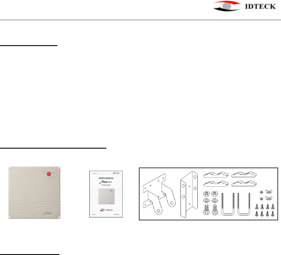
2. Identifying supplied parts
Please unpack and check the contents of the box.
RF70 User’s Manual Mounting Bracket (Optional purchase)
3. Specification
Read Range Up to 28” (70cm) with IDC170 cards
Up to 5 foot (1.5m) with IDA150 cards
Up to 7 foot (2.1m) with IDA200 cards
Output Format 26 bit Wiegand, ABA Track II Magstripe, RS232
External Beeper Control Input Low Active, DC 0 ~ 12V, maximum 50 mA
External LED Control Input Low Active, DC 0 ~ 12V, maximum 50 mA
LED/Beeper 2-Color LED (Red and Green) / Piezo Buzzer
Color Light Gray, Dark Gray
Power DC12V, maximum 500mA
Operating Environment -31
℉
~ 149
℉
(-35
℃
~ +65
℃
), 0~90% Humidity
Overall Size (WxHxD) 11.4"x 11.4"x2.4" (290x290x60mm)
Weight 7.0 lbs (3.2kg)

STAR RF70 PROXIMITY READER
20021214 USER’S MANUAL 4
4. Installation
4-1. Pole Mount using Mounting Bracket (Optional purchase)
Install the RF70 to the mounting plate and install the mounting bracket to the pole as
shown in the photos below, and then adjust the angle of the reader toward the tags.
(1) Install mounting plate to RF70 (2) Assemble “U” bolt to bracket
by using 8 screws
(3) Assemble bracket to mounting (4) Install mounting bracket to the pole
plate by using 2 hex bolts/nuts then adjust the angle of the reader
STAR RF70 PROXIMITY READER
20021214 USER’S MANUAL 5
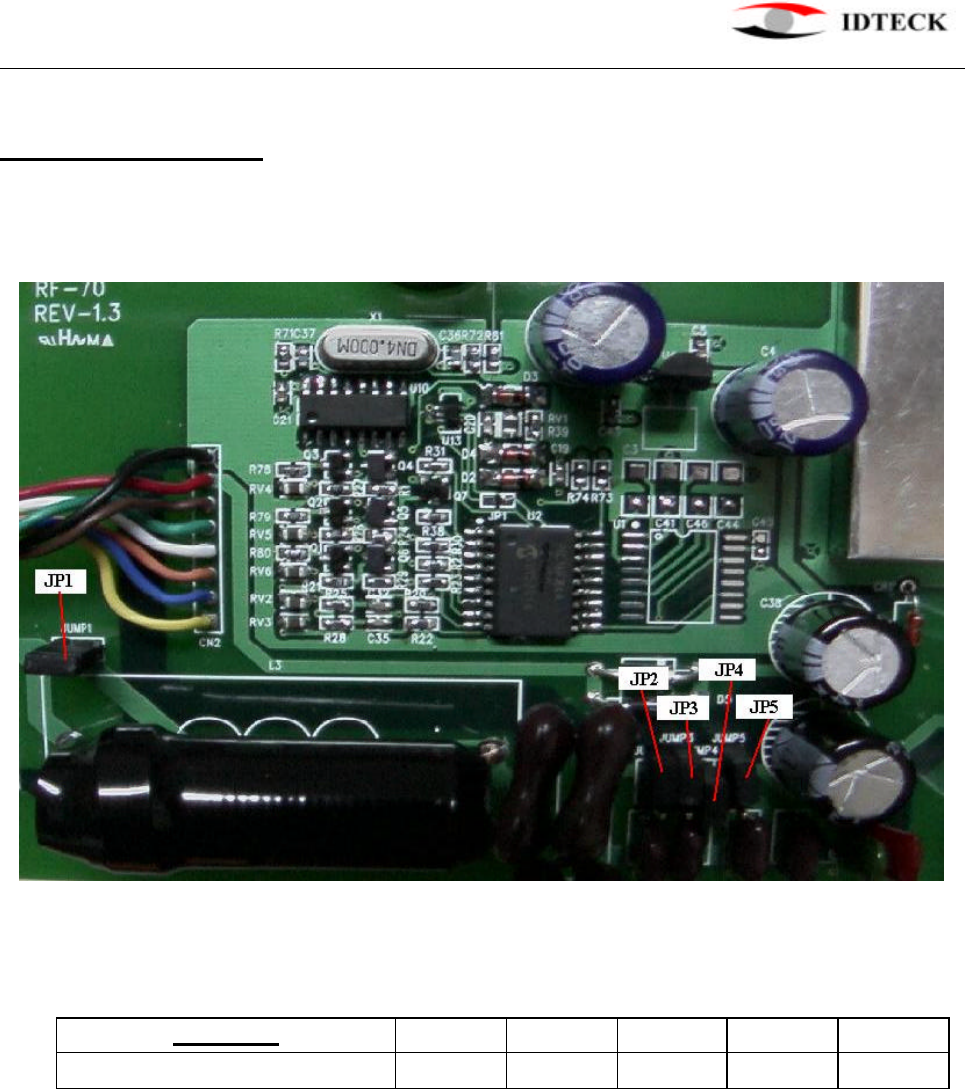
5. Jumper location
Open the top cabinet and there are 5 jumpers in the unit and the location of jumpers
are shown in the photo below.
The jumpers needs to be set as shown below.
JUMPER JP1 JP2 JP3 JP4 JP5
ON/OFF Off On On On On
STAR RF70 PROXIMITY READER
20021214 USER’S MANUAL 6
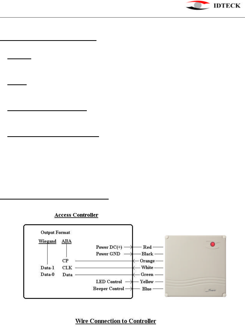
6. Wire Color Table of RF70
POWER
Power (DC +12V) DC(+) Red wire
Power (DC Ground) DC(-)(GND) Black wire
INPUT
Beeper control input BEEP Blue wire
LED control input LED Yellow wire
OUTPUT (Wiegand Format)
Wiegand Data-0 Data-0 Green wire
Wiegand Data-1 Data-1 White wire
OUTPUT (ABA Track II Format)
ABA(Card Present) CP Orange wire
ABA(Clock) CLK White wire
ABA(Data) Data Green wire
Note: All ABA Track II outputs are open collector output.
7. Wire Connection to controller

STAR RF70 PROXIMITY READER
20021214 USER’S MANUAL 7
8. Operation
8-1. Once power is applied, you should hear three beeping sounds and LED changes color
to red-green-red indicating that the reader is in standby mode after a successful
initialization and diagnosis.
8-2. Present proximity card to the reader until you hear the beeping sound and see the LED
changes color to green. The reader will send the proximity card data to the controller
then the LED will change color to red again for the next reading.
8-3. LED Control:
To change the LED colors, you may connect the LED Control Input (Yellow wire) to
ground and the green LED will turn on indicating that the reader is in standby mode.
Present proximity card and the LED will change color to red then green again for the
next reading.
8-4. Beeper Control:
In normal operation, the reader generates one beep when it reads a proximity card,
however additional beeps can be generated to improve indication for access status
(granted or denied) by forcing the beeper control input (Blue wire) to system ground
level. The beeper will remain on as long as the Blue wire is connected to system
ground.
9. FCC REGISTRATION INFORMATION
FCC REQUIREMENTS PART 15
Caution: Any changes or modifications in construction of this device which are not expressly
approved by the responsible for compliance could void the user's authority to
operate the equipment.
NOTE: This device complies with Part 15 of the FCC Rules.
Operation is subject to the following two conditions;
1. This device may not cause harmful interface, and
2. This device must accept any interference received, including interference that may cause
undesired operation.
This equipment has been tested and found to comply with the limits for a Class A Digital
Device, pursuant to Part 15 of the FCC Rules. These limits are designed to this equipment
generates, uses, and can radiate radio frequency energy and, if not installed and used in
accordance with the instructions, may cause harmful interference to radio communications.
However, there is no guarantee that interference will not occur in a particular installation. If
this equipment does cause harmful interference to radio or television reception, which can be
determined by turning the radio or television off and on, the user is encouraged to try to
correct interference by one or more of the following measures.

STAR RF70 PROXIMITY READER
20021214 USER’S MANUAL 8
1. Reorient or relocate the receiving antenna.
2. Increase the separation between the equipment and receiver.
3. Connect the equipment into an outlet on another circuit.
4. Consult the dealer or an experienced radio/TV technician for help.
10. Warranty and Service
The following warranty and service information applies only to the United States of America
and Republic of Korea. For the information in other countries, please contact your local
distributor. To obtain in or out of warranty service, please prepay shipment and return the
unit to the appropriate facility listed below.
OUTSIDE OF THE UNITED STATES
ID TECK CO., LTD. Service Center
5F Ace Techno Tower Bldg.,
684-1 Deungchon-dong, Gangsuh-gu,
SEOUL 157-030, KOREA
Tel.: +82 (2) 2659-0055
Fax.: +82 (2) 2659-0086
E-mail: webmaster@idteck.com
Web-site: www.idteck.com
IN THE UNITED STATES
RF LOGICS Inc. Service Center
3026 Scott Blvd.,
SANTA CLARA, CA95054
Tel.: (408) 980-0001
Fax.: (408) 980-8060
E-mail: rflogics@rflogics.com
Web-site: www.rflogics.com
Please use the original container, or pack the unit(s) in a sturdy carton with sufficient packing
to prevent damage, include the following information:
1. A proof-of-purchase indicating model number and date of purchase.
2. Bill-to address
3. Ship-to address
4. Number and description of units shipped.
5. Name and telephone number of person to contact.
6. Reason for return and description of the problem.
NOTE: Damage occurring during shipment is deemed the responsibility of the carrier, and
claims should be made directly to the carrier.