ID Teck Co STARRFK101 Proximity Reader With Keypad User Manual INSTRUCTION
ID-Teck Co Ltd Proximity Reader With Keypad INSTRUCTION
user manual
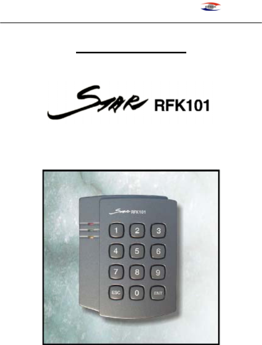
STAR RFK101 PROXIMITY READER
ID-TECK
INSTRUCTION
Proximity Reader with KEYPAD
ID TECK Co. Ltd.
RFK101-20011219 - 1 -

STAR RFK101 PROXIMITY READER
ID-TECK
CONTENTS
1. Introduction page 3
2. Identifying supplied parts page 3
3. Specification page 3
4. Installation page 4
5. Wire Color Table of the Reader page 5
6. Wire Connection to Controller page 6
7. Operation page 7
8. Output Format page 9
9. FCC Registration Information page 13
10. Warranty and Service page 14
RFK101-20011219 - 2 -
STAR RFK101 PROXIMITY READER
ID-TECK
1. Introduction
The STAR RFK101 is an elegant looking and built in an attractive 4" read range proximity reader
with KEYPAD. The RFK101 has back lighting on the KEYPAD that ensure you successful
operation even the night operating. The KEYPAD allows you to access door with proximity card
and personal PIN numbers.
Three LEDs of green, yellow and red, inside Piezo buzzer sound will guarantee you an accurate
and reliable system operations.
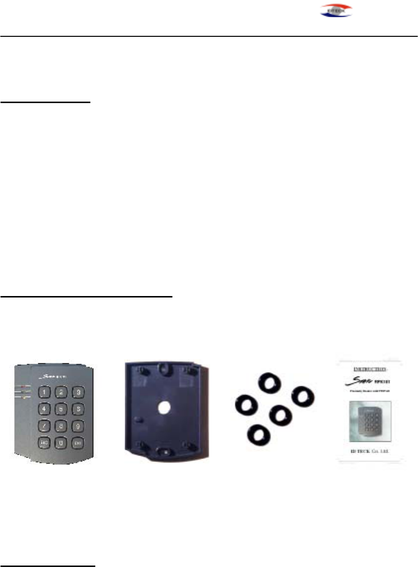
2. Identifying supplied parts
Please unpack and check the contents of the box.
Reader unit Wall Mount O-ring Instructions
(1 ea) (1 ea) (5 ea) (1 ea)
3. Specification
Read Range/Time Up to 4"(10cm) / 30ms
Input Voltage/Current DC 12V, 150mA
Reset Power on reset and WDT reset
LED/Beeper 3 LEDs(Red, Yellow and Green) / Piezo Buzzer
Keypad 12key, Back lighting
RFK101-20011219 - 3 -
STAR RFK101 PROXIMITY READER
ID-TECK
Color Dark Pearl Gray
Operating Environment -35℃ ~ +65℃, 10~90% Humidity
Overall Size(WxHxD) 3.40"x3.94"x1.22"(487x100x31mm)
Weight 0.412 lbs(190 g)
Output Format 26bit Wiegand, RS-232, ABA Track II Magstripe Output
Format with 8bit Burst or 3x4 Matrix Format for PIN
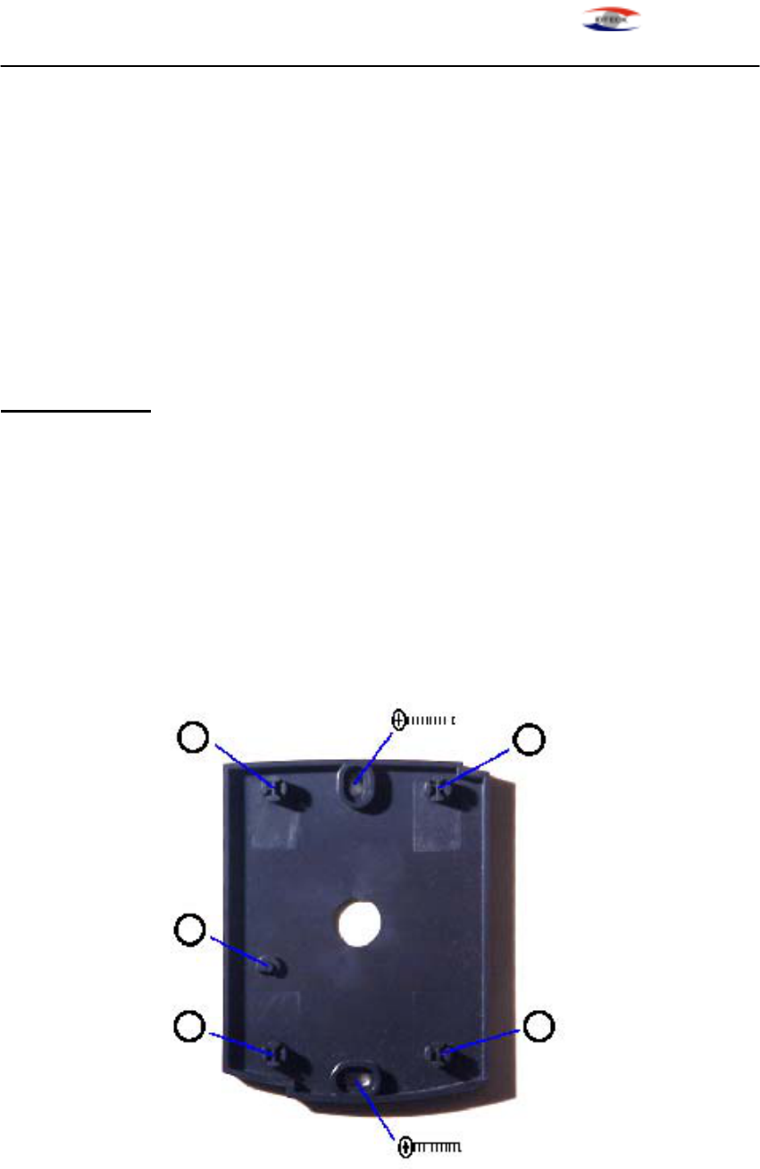
4. Installation
4-1. Drill two 6-32 or M3 holes 3.3"(8.38cm) apart in vertical and one 1/2" hole at the center of
these two holes. (If you have installed electric gang box then skip this step.)
4-2. Using two 6-32 or M3 screws, install wall mount to the wall.
4-3. Insert 5 O-rings to the wall mount as indicated, then route the cable of the main unit through
the center hole and push the main unit to wall mount to lock the main unit and make sure
that the main unit is locked with wall mount.
RFK101-20011219 - 4 -

STAR RFK101 PROXIMITY READER
ID-TECK
5. Wire Color Table of the Reader
POWER
Power(DC 12V) +12V Red wire
Power(DC 12V) 0V(GND) Black wire
OUTPUT
ABA Track II(Card Present) CLS Yellow wire
ABA Track II(Clock), Wiegand Data1 RD1 White wire
ABA Track II(Data), Wiegand Data0 RD0 Green wire
RS-232 TX TX Violet wire
KEYPAD 3x4 Matrix(Column0) C0 White wire with blue band
KEYPAD 3x4 Matrix(Column1) C1 White wire with green band
KEYPAD 3x4 Matrix(Column2) C2 White wire with red band
KEYPAD 3x4 Matrix(Row0) R0 Cyan wire
KEYPAD 3x4 Matrix(Row1) R1 Pink wire
KEYPAD 3x4 Matrix(Row2) R2 Orange wire
KEYPAD 3x4 Matrix(Row3) R3 Gray wire
INPUT
LED Control LED Brown wire
Beeper Control BEEP Blue wire
RFK101-20011219 - 5 -
STAR RFK101 PROXIMITY READER
ID-TECK
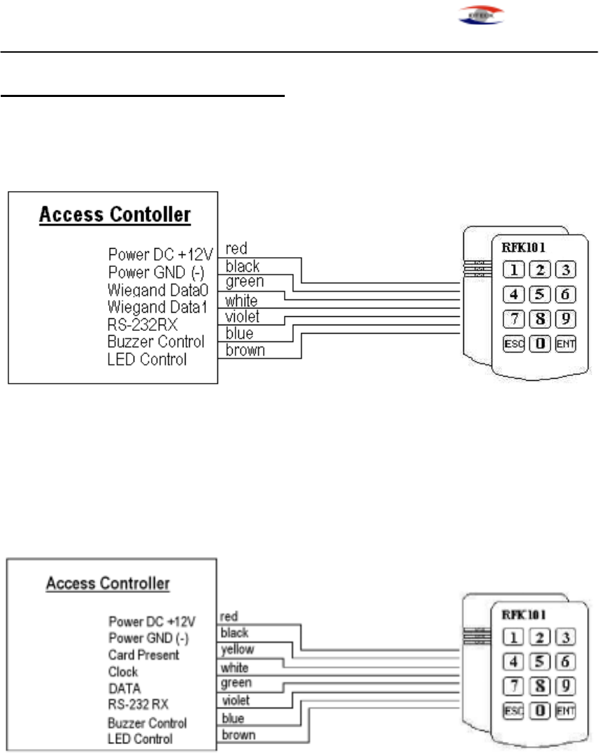
6. Wire Connection to Controller
6-1. 26bit Weigand+RS232(for Card) and 8bit Burst format(for PIN)
. The Reader transmits Card data to Wiegand Data0,Data1 and RS-232 TX line.
. The Reader transmits PIN data to Wiegand Data0 and Data1.(8bit Burst format.)
6-2. ABA Track II+RS232(for Card) and ABA Track II+RS232(for PIN)
. The Reader transmits Card and PIN data to Card present, Clock, DATA and RS-232 TX line.
NOTE : You have to enter at least 1 numeric number(max. 8 numbers) followed by "ENT" key.
RFK101-20011219 - 6 -
STAR RFK101 PROXIMITY READER
ID-TECK
7. Operation
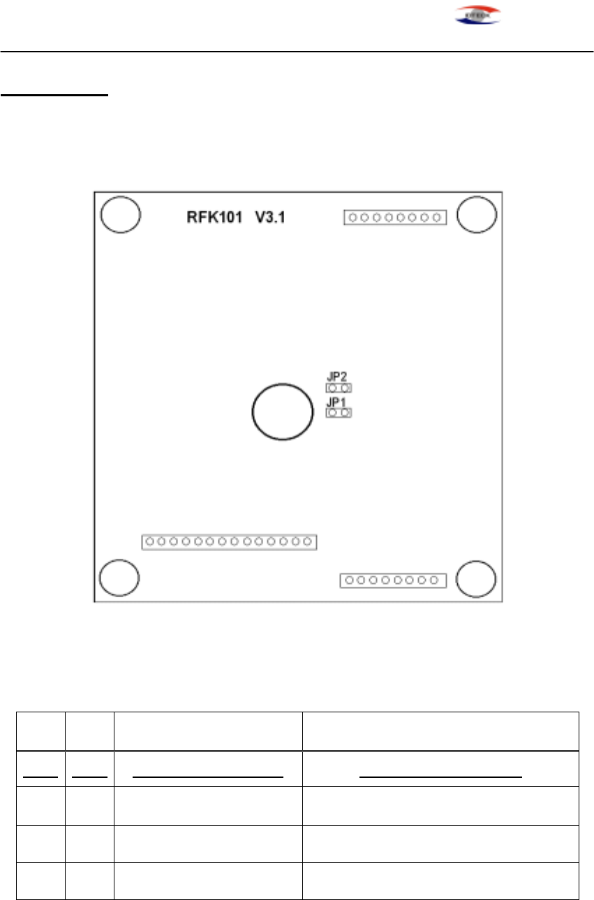
7-1. Connector Layout
7-2. Output mode Setting
Table 1. Jumpers Setting
JP1 JP2 Card Output format Keypad Output format
close close 26bit Wiegand + RS232 8bit Burst (or 3x4 Matrix)
open close 26bit Wiegand + RS232 26bit Wiegand + RS232(or 3x4 Matrix)
close open ABA Track II + RS232 8bit Burst (or 3x4 Matrix)
open open ABA Track II + RS23 ABA Track II + RS232 (or 3x4 Matrix)
Note: Default setting value for JP1 and JP2 jumpers are “close”(short circuit)
RFK101-20011219 - 7 -

STAR RFK101 PROXIMITY READER
ID-TECK
7-3. Operation
1. Once the power is applied, you should hear 3 times of initial beep sounds and red
And yellow LEDs on indicating that the reader is in standby mode after a
successful initialization and diagnostics.
2. Present proximity card to the reader until you hear the beeping sound and the
green LED on. The reader will send the RF card data to the controller then the
yellow LED on again for the next reading.
3. Enter the Keypad until you hear the beeping sound. The reader will send the Key
data to the controller.
4. LED Control:
To change the LED colors, you may connect the LED Control Input (brown wire) to
ground and the green LED will turn on indicating that the reader is in standby
mode. Present proximity card and the LED will change color to yellow then green
again for the next reading.
5. Beeper Control:
In normal operation, the reader generates one beep when it reads a proximity card,
However additional beeps can be generated to improve indication for access
status(granted or denied) by forcing the Beeper Control Input, blue wire to system
ground level. The beeper will remain on as long as the blue wire is connected to
system ground.
RFK101-20011219 - 8 -
STAR RFK101 PROXIMITY READER
ID-TECK
8. Output Format
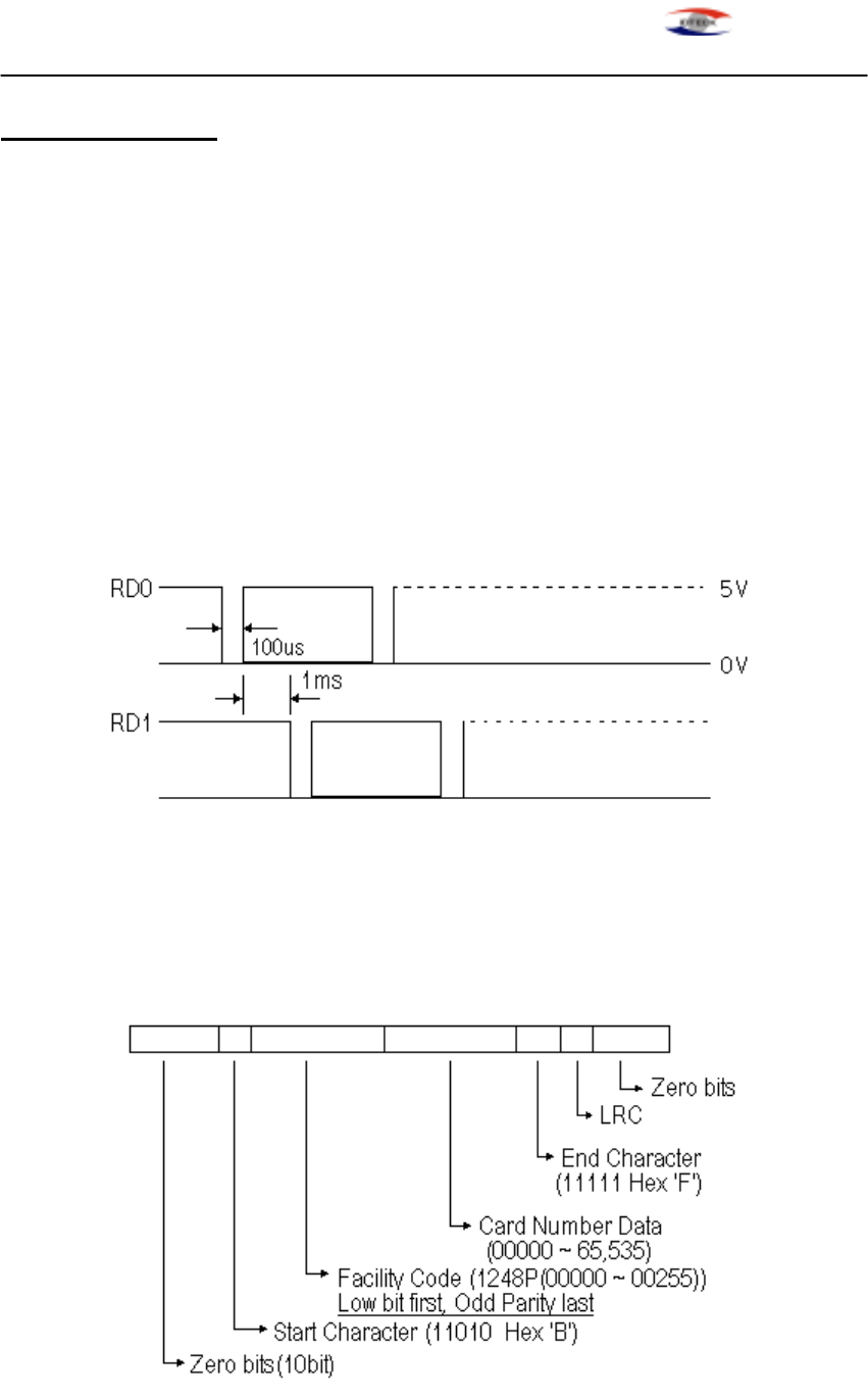
8-1. 26bit Wiegand output format
1. Data format
Bit 1 : Even parity of bit 2 ~ bit 13
Bit 2~9 : Facility code (000 ~ 255)
Bit 10~25 : ID number (00000 ~ 65,535)
Bit 26 : Odd parity of bit 14 ~ bit 25
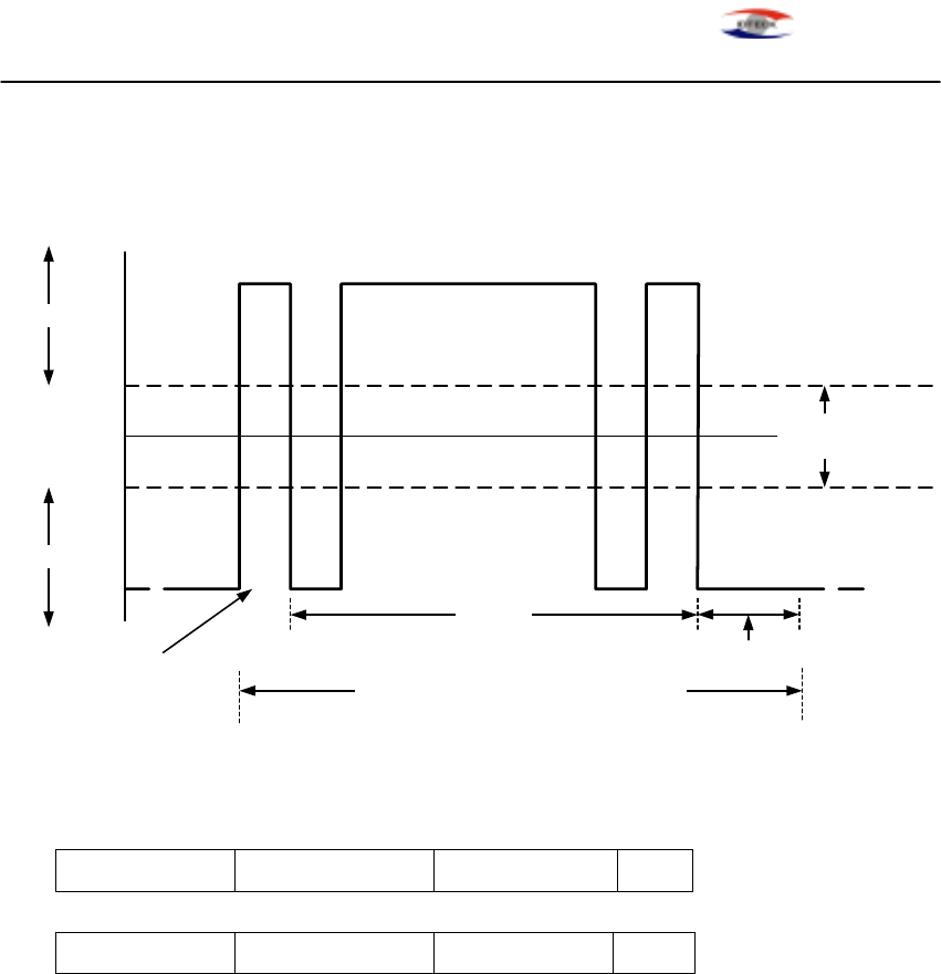
2. Timing diagram
8-2. ABA Track II Magstripe output format
1. Data format(for Card numbers)
RFK101-20011219 - 9 -
STAR RFK101 PROXIMITY READER
ID-TECK
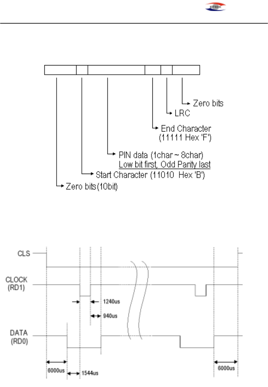
2. Data format(for PIN)
3. Timing diagram
RFK101-20011219 - 10 -
STAR RFK101 PROXIMITY READER
ID-TECK
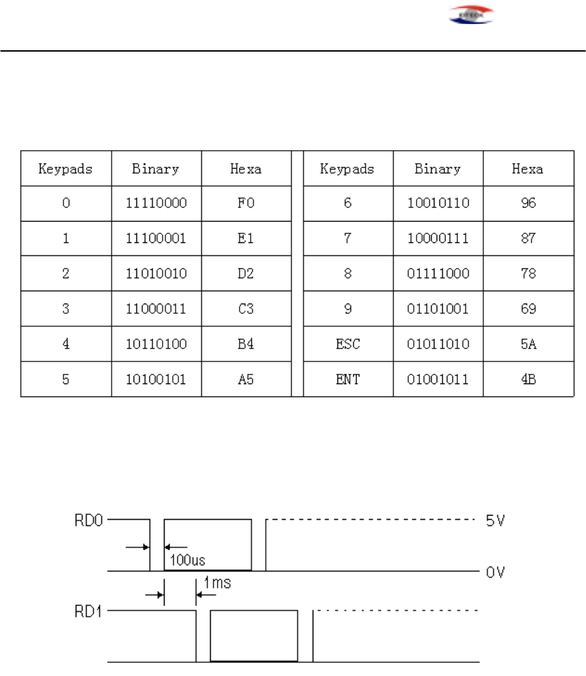
8-3. 8bit Burst output format(for PIN)
1. Data format
2. Timing diagram
RFK101-20011219 - 11 -
STAR RFK101 PROXIMITY READER
ID-TECK
8-4. RS-232 output format
1. Data format(Baud rate : 9600bps)
+15V
-15V
+3V
-3V
Space (=0)
Mark (=1)
8 Data Bits
2 Stop Bits
Indeterminate
Region
Data packet corresponding to ASCII character 'A'
Start Bit
010000010
LSB MSB
0V
2. Data structure
START(0X02H) DATA(8 Char) END(0x03H) LRC (CARD output)
START(0X02H) DATA(1~8 Char) END(0x03H) LRC (Keypad output)
8-5. Matrix(3x4) format
1. Data format
Column0 Column1 Column2
↓ ↓ ↓
Row0 → 1 2 3
Row1 → 4 5 6
Row2 → 7 8 9
Row3 → ESC 0 ENT
RFK101-20011219 - 12 -

STAR RFK101 PROXIMITY READER
ID-TECK
9. FCC REGISTRATION INFORMATION
FCC REQUIREMENTS PART 15
Caution: Any changes or modifications in construction of this device which are not expressly approved
by the responsible for compliance could void the user's authority to operate the equipment.
NOTE: This device complies with Part 15 of the FCC Rules.
Operation is subject to the following two conditions;
1. This device may not cause harmful interference, and
2. This device must accept any interference received, including interference that may cause undesired
operation.
This equipment has been tested and found to comply with the limits for a Class A Digital Device,
pursuant to Part 15 of the FCC Rules. These limits are designed to this equipment generates, uses, and
can radiate radio frequency energy and, if not installed and used in accordance with the instructions, may
cause harmful interference to radio communications.
However, there is no guarantee that interference will not occur in a particular installation. If this
equipment does cause harmful interference to radio or television reception, which can be determined by
turning the radio or television off and on, the user is encouraged to try to correct interference by one or
more of the following measures.
1. Reorient or relocate the receiving antenna.
2. Increase the separation between the equipment and receiver.
3. Connect the equipment into an outlet on another circuit.
4. Consult the dealer or an experienced radio/TV technician for help.
RFK101-20011219 - 13 -

STAR RFK101 PROXIMITY READER
ID-TECK
10. Warranty and Service
The following warranty and service information applies only to the United States of America and
Republic of Korea. For the information in other countries, please contact your local distributor.
To obtain in or out of warranty service, please prepay shipment and return the unit to the service
facility listed below.
IN THE UNITED STATES
RF LOGICS Inc. Service Center
3026 Scott Blvd.,
SANTA CLARA, CA95054
Tel.: (408) 980-0001
Fax.: (408) 980-8060
E-mail: rflogics@rflogics.com
Web-site: www.rflogics.com
OUTSIDE OF THE UNITED STATES
ID TECK CO., LTD. Service Center
5F Ace Techno Tower B/D,
684-1 Deungchon-Dong, Kangsuh-Gu,
SEOUL, KOREA 157-030
Tel.: +82 (2) 659-0055
Fax.: +82 (2) 659-0086
E-mail: webmaster@idteck.com
Web-site: www.idteck.com
RFK101-20011219 - 14 -