IDEMIA Identity and Security France MPHAC004A Access Control Terminal with biometric identification User Manual Tender Offer
IDEMIA Identity & Security France Access Control Terminal with biometric identification Tender Offer
User manual - ZBW-MPHAC004A.pdf
Copyright 2018 Idemia
May 2018 | 2018_2000035853
MorphoWave Compact
Installation guide

Copyright 2018 Idemia
May 2018 | 2018_2000035853

3
MorphoWave Compact - 2018_2000035853
Warning
COPYRIGHT © 2018 Idemia. All rights reserved.
Reproduction in whole or in part in any form or medium without the express written permission of Idemia
is prohibited. The trademarks identified herein are the trademarks of registered trademarks of Idemia, or
other third party.
This legend is applicable to all pages of this document.
Information in this document is subject to change without notice and do not represent a commitment on
the part of Idemia.
This manual makes reference to names and products that are trademarks of their respective owners.

4
MorphoWave Compact - 2018_2000035853
Revision history
Version
Date
Reference
Description
01
May 2018
2018_2000035853
Document creation

5
MorphoWave Compact - 2018_2000035853
Table of content
1 / Introduction 8
1.1 > MorphoWave Compact terminal 9
1.2 > Scope of the document 10
1.3 > Safety Instructions 11
1.4 > Wiring Recommendations 12
1.5 > Regulatory, safety and Environmental notices 13
1.5.1 > European Union (CE) regulatory notices 13
1.5.2 > USA (FCC) regulatory notices 14
1.5.3 > Canada (IC) regulatory notices 15
1.6 > Others recommendations 16
1.7 > Recommendations for terminal implementation 17
2 / General description 20
2.1 > Box opening 21
2.2 > Components of the initial package 22
2.3 > Terminal's front view description 23
2.4 > Terminal's rear view description 24
2.5 > MorphoWave Compact Technical Characteristics 25
3 / Installation procedure 28
3.1 > Before proceeding to the installation 29
3.2 > Installation 30
3.3 > Step by step procedure 31
3.3.1 > Drill the mounting holes 32
3.3.2 > Make the connections 33
3.3.3 > Attach the base plate on the wall 35
3.3.4 > Attach the device on the base plate 36
3.3.5 > Connect the connector assembly on the device 37
3.3.6 > Close the device on the base plate 38
4 / Electrical interface 40
4.1 > Wiring overview 41
4.2 > Power Supply 42

6
MorphoWave Compact - 2018_2000035853
4.3 > Output Relay 44
4.4 > Tamper Switch 45
4.5 > Wiegand wiring 46
4.6 > Wiegand output 47
4.7 > Serial port wiring 49
4.8 > GPIO wiring 51
4.9 > Ethernet connection 52
4.10 > Internal USB connection 53
4.11 > Wi-Fi™ dongle installation 55
5 / User interface 57
5.1 > Modes for controlling access rights 58
5.1.1 > Introduction 58
5.1.2 > Identification mode 58
5.1.3 > Authentication (verification) mode 58
5.1.4 > Multi-factor mode 58
5.1.5 > Proxy mode 59
5.1.6 > External database mode (also called polling mode) 59
5.1.7 > MorphoWave Compact native mode 61
5.1.8 > Anti-tamper / anti-pulling switches 62
6 / Accessories, Software Licenses and PC Applications 63
6.1 > Compatible Accessories, Licenses and Software 64
6.2 > Compatible PC applications 65
7 / Recommendations 66
8 / Annex 1 : finger placement recommendations 69
8.1 > Main principles 70
8.2 > Capture recommendations 71
Proper Use 71
Improper Use 72
9 / Annex 2 : Bibliography 74
9.1 > How to get the latest versions of documents 75
9.2 > Documents about the MorphoWave Compact terminal 76
10 / Annex 3 : Support 77
10.1 > Troubleshooting 78
10.2 > Technical Support and Hotline 78

7
MorphoWave Compact - 2018_2000035853
1 / Introduction 9
1.1 > MorphoWave Compact terminal 10
1.2 > Scope of the document 11
1.3 > Safety Instructions 12
1.4 > Wiring Recommendations 13
1.5 > Regulatory, safety and Environmental notices 14
1.5.1 > European Union (CE) regulatory notices 14
1.5.2 > USA (FCC) regulatory notices 15
1.5.3 > Canada (IC) regulatory notices 16
1.6 > Others recommendations 17
1.7 > Recommendations for terminal implementation 18
2 / General description 21
2.1 > Box opening 22
2.2 > Components of the initial package 23
2.3 > Terminal's front view description 24
2.4 > Terminal's rear view description 25
2.5 > MorphoWave Compact Technical Characteristics 26
3 / Installation procedure 29
3.1 > Before proceeding to the installation 30
3.2 > Installation 31
3.3 > Step by step procedure 32
3.3.1 > Drill the mounting holes 33
3.3.2 > Make the connections 34
3.3.3 > Attach the base plate on the wall 36
3.3.4 > Attach the device on the base plate 37
3.3.5 > Connect the connector assembly on the device 38
3.3.6 > Close the device on the base plate 39
4 / Electrical interface 41
4.1 > Wiring overview 42
4.2 > Power Supply 43
4.3 > Output Relay 45
4.4 > Tamper Switch 46
4.5 > Wiegand wiring 47
4.6 > Wiegand output 48

8
MorphoWave Compact - 2018_2000035853
4.7 > Serial port wiring 50
4.8 > GPIO wiring 52
4.9 > Ethernet connection 53
4.10 > Internal USB connection 54
4.11 > Wi-Fi™ dongle installation 56
5 / User interface 58
5.1 > Modes for controlling access rights 59
5.1.1 > Introduction 59
5.1.2 > Identification mode 59
5.1.3 > Authentication (verification) mode 59
5.1.4 > Multi-factor mode 59
5.1.5 > Proxy mode 60
5.1.6 > External database mode (also called polling mode) 60
5.1.7 > MorphoWave Compact native mode 62
5.1.8 > Anti-tamper / anti-pulling switches 63
6 / Accessories, Software Licenses and PC Applications 64
6.1 > Compatible Accessories, Licenses and Software 65
6.2 > Compatible PC applications 66
7 / Recommendations 67
8 / Annex 1 : finger placement recommendations 70
8.1 > Main principles 71
8.2 > Capture recommendations 72
Proper Use 72
Improper Use 73
9 / Annex 2 : Bibliography 75
9.1 > How to get the latest versions of documents 76
9.2 > Documents about the MorphoWave Compact terminal 77
10 / Annex 3 : Support 78
10.1 > Troubleshooting 79
10.2 > Technical Support and Hotline 79

9
MorphoWave Compact - 2018_2000035853
1 / Introduction

10
MorphoWave Compact - 2018_2000035853
1.1 > MorphoWave Compact terminal
Congratulations for choosing MorphoWave Compact Automatic Fingerprint Recognition Terminal!
MorphoWave Compact provides an innovative and effective solution for access control applications using
very fast acquisitions of four (4) fingerprints without any contact.
Among a range of alternative biometric technologies, the use of finger imaging has significant advantages:
very fast acquisition from a single wave of the hand through the sensor, and no physical contact between
the applicant and the glass.
Each finger constitutes an unalterable physical signature, developed before birth and preserved until
death. Unlike DNA, a finger image is unique to each individual - even identical twins.
By “on-the-fly”, we mean:
Contactless acquisition: The user does NOT need to touch any part of the sensor
Acquisition in movement: Users swipe their hand across the sensor; no need to stop & position fingers.
At the end of the swipe, the acquisition is complete.
MorphoWave Compact integrates Idemia image processing and feature matching algorithms. This
technology is based on lessons learned during 25 years of experience in the field of biometric identification
and the creation of literally millions of individual fingerprint identification records.
We believe you will find the MorphoWave Compact fast, accurate, easy to use and suitable for physical
access control.
The MorphoWave Compact offers the following advantages:
high quality optical sensor with false finger detection option,
supports multiple input/output interfaces used in the physical access control industry,
Local Area Network interface for easy interaction with other host systems ; LAN and WLAN possibilities
(Wi-Fi™ as an option),
intuitive man machine interface with touch panel and display, that is easy to use in both setup and
operational modes,
sturdy wall mounting with easy holding of product during cabling or maintenance,
To ensure the most effective use of your MorphoWave Compact terminal, we recommend that you read this
Installation Guide completely.

11
MorphoWave Compact - 2018_2000035853
1.2 > Scope of the document
This guide deals with the installation of MorphoWave Compact, which is made up of the following list of
products:
MorphoWave Compact Marketing
Name
Biometrics
Fake
Finger
Detection
Contactless smartcard reader
Water
Resistant
Regulatory
Model Number
(*)
iCLASS®
MIFARE®
DESFire®
NFC
Prox®
MorphoWave Compact MD
MPH-AC004A
MorphoWave Compact MDPI
MPH-AC004B
(*) The Regulatory Model Number is the main product identifier in the regulatory documentation and test
reports associated to the product

12
MorphoWave Compact - 2018_2000035853
1.3 > Safety Instructions
means Direct Current (DC)
The installation of this product should be made by a qualified service Person and should comply with all
local regulations.
It is strongly recommended to use a class II power supply at 12V-24V and 2.5 A. min (at 12V) in conformity
with Safety Electrical Low Voltage (SELV). The power supply cable length should not exceed 10 meters.
This system must be installed in accordance with the National Electrical Code (NFPA 70), and the local
authority having jurisdiction.
This product is intended to be installed with a power supply complying with IEC60950-1, in accordance
with the NEC Class 2 requirements; or supplied by a listed IEC60950-1 external Power Unit marked Class
2, Limited Power source, or LPS and rated 12VDC, 2.5 A minimum or 24VDC, 1.25 A minimum.
In case of building-to-building connection it is recommended to connect 0V to ground. Ground cable must
be connected with the terminal block Power Ground.
Note that all connections of the MorphoWave Compact terminal described hereafter are of SELV (Safety
Electrical Low Voltage) type.
13
MorphoWave Compact - 2018_2000035853
1.4 > Wiring Recommendations
Idemia recommends using a AWG16 gauge and 24V power supply when PoE+ supply is not used.
The voltage specified is the one measured on the product block connector:
12V-24V (-15% / +10%).
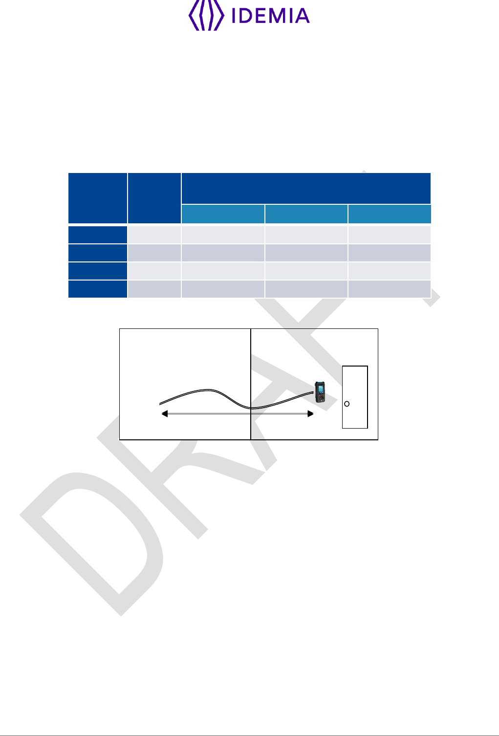
The voltage drop due to the cable shall be taken into account. The following table shows the maximum
distance between power supply and one (1) unique device, depending on cable gauge and power supply
rating:
Gauge
AWG
Section
(mm2)
Maximum distance (meters) vs power
source rating
12V+/-10%
12V+/-5%
24V+/-10%
16
1.31
9 m
20 m
300 m
18
0.82
6 m
12 m
200 m
20
0.52
3 m
8 m
120 m
22
0.32
2 m
5 m
75 m
Drop voltage = loss of power due to wire resistance and its length: V2 = V1 – Drop voltage
V1
V2
L

14
MorphoWave Compact - 2018_2000035853
1.5 > Regulatory, safety and Environmental notices
1.5.1 > European Union (CE) regulatory notices
Declaration of Conformity
Products bearing the CE marking comply with one or more of the following EU Directives as may be
applicable:
Low Voltage Directive 2006/95/EC
EMC Directive 2004/108/EC
R&TTE Directive 1999/5/EC
Ecodesign Directive 2009/125/EC
RoHS Directive 2011/65/EU.
Compliance with these directives is assessed using applicable European Harmonised Standards.
MorphoWave Compact terminals are intended to be used for professional application only (buildings,
airport...).
This is an EMC Class A product according to EMC directive 2004/108/EC. This product may cause
interference if used in residential areas. Such use must be avoided unless the user takes special measures
to reduce magnetic emissions to prevent interference to the reception of radio and television broadcast.
The full Declaration of Conformity is available on demand to your reseller. Please, provide him the product
model name or its Regulatory Model Number (Model on the label).
Products with wireless features (EMF)
This product meets the provisions of the EU's Council recommendation 1999/519/EC on the limitation of
the exposure of the general public to electromagnetic fields (0 Hz to 300 GHz).
15
MorphoWave Compact - 2018_2000035853
1.5.2 > USA (FCC) regulatory notices
This device complies with part 15 of the FCC Rules. Operation is subject to the following
two conditions: (1) this device may not cause harmful interference, and (2) this device must
accept any interference received, including interference that may cause undesired
operation.
This device complies with FCC RF radiation exposure limits set forth for general population.
This device must be installed to provide a separation distance of at least 20cm from all
persons and must not be co-located or operating in conjunction with any other antenna or
transmitter
Changes or modifications not expressly approved by the party responsible for compliance could void the
user's authority to operate the equipment.
Responsible Party:
Idemia
11, boulevard Gallieni
92130 Issy-les-Moulineaux – France
NOTA : This equipment has been tested and found to comply with the limits for a Class B digital
device, pursuant to Part 15 of the FCC Rules. These limits are designed to provide
reasonable protection against harmful interference in a residential installation. This
equipment generates, uses and can radiate radio frequency energy and, if not installed
and used in accordance with the instructions, may cause harmful interference to radio
communications. However, there is no guarantee that interference will not occur in a
particular installation. If this equipment does cause harmful interference to radio or
television reception, which can be determined by turning the equipment off and on, the
user is encouraged to try to correct the interference by one of the following measures:
Reorient or relocate the receiving antenna.
Increase the separation between the equipment and receiver.
Connect the equipment into an outlet on a circuit different from that to which the receiver is connected.
Consult the dealer or an experienced radio/TV technician for help.
Shielded cables must be used with this unit to ensure compliance with category B FCC restrictions.
MPH-AC004B product model includes a module tested under the FCC rules for a Modular Approval.
o FCCID: JQ6-SE3210

16
MorphoWave Compact - 2018_2000035853
1.5.3 > Canada (IC) regulatory notices
WARNING TO USERS IN THE CANADA / ATTENTION POUR LES UTILISATEURS AU CANADA
This device complies with Industry Canada license-exempt RSS standard(s). Operation is subject to the
following two conditions: (1) this device may not cause interference, and (2) this device must accept any
interference, including interference that may cause undesired operation of the device.
Under Industry Canada regulations, this radio transmitter may only operate using an antenna of a type
and maximum (or lesser) gain approved for the transmitter by Industry Canada.
To reduce potential radio interference to other users, the antenna type and its gain should be so chosen
that the equivalent isotropically radiated power (e.i.r.p.) is not more than that necessary for successful
communication.
This device complies with Industry Canada RF radiation exposure limits set forth for general population.
This device must be installed to provide a separation distance of at least 20cm from all persons and must
not be co-located or operating in conjunction with any other antenna or transmitter.
Note: UL LLC has not verified this product for compliance in respect to Canadian standards.
MPH-AC004B product model includes a module compliant with limits set by Industry Canada
o IC: 2236B-SE3210
Le présent appareil est conforme aux CNR d’Industrie Canada applicables aux appareils radio exempts
de licence. L’exploitation est autorisée aux deux conditions suivantes:
1) l’appareil ne doit pas produire de brouillage, et
2) l’utilisateur de l’appareil doit accepter tout brouillage radioélectrique subi, même si le brouillage est
susceptible d’en compromettre le fonctionnement.
Conformément à la réglementation d’Industrie Canada, le présent émetteur radio peut fonctionner avec
une antenne d’un type et d’un gain maximal (ou inférieur) approuvé pour l’émetteur par Industrie Canada.
Dans le but de réduire les risques de brouillage radioélectrique à l’intention des autres utilisateurs, il faut
choisir le type d’antenne et son gain de sorte que la puissance isotrope rayonnée équivalente (p.i.r.e.) ne
dépasse pas l’intensité nécessaire à l’établissement d’une communication satisfaisante.
Le présent appareil est conforme aux niveaux limites d’exigences d’exposition RF aux personnes définies
par Industrie Canada. L’appareil doit être installé afin d’offrir une distance de séparation d’au moins 20cm
avec l’utilisateur, et ne doit pas être installé à proximité ou être utilisé en conjonction avec une autre
antenne ou un autre émetteur.
Le modèle de produit MPH-AC004B intègre un module conforme aux limites d’exigences définies par
Industrie Canada.
o IC: JQ6-SE3210

17
MorphoWave Compact - 2018_2000035853
1.6 > Others recommendations
Potential safety conditions notice
If you notice any of the following conditions (or if you have other safety concerns), do not use the product:
crackling, hissing, or popping sound, or a strong odor or smoke coming from the product. It is normal for
these conditions to appear when an internal electronic component fails in a safe and controlled manner.
However, these conditions may also indicate a potential safety issue. Do not assume it is a safe failure.
Turn off the product, disconnect it from its power source, and contact technical support for assistance.
Disposal of waste equipment by users
This symbol means do not dispose of your product with your other household waste. Instead, you should
protect human health and the environment by handing over your waste equipment to a designated
collection point for the recycling of waste electrical and electronic equipment.

18
MorphoWave Compact - 2018_2000035853
1.7 > Recommendations for terminal implementation
Every installation is unique. Sometimes the issues are well defined and can be handled in a standard
fashion; sometimes the issues are very specific and may not be immediately recognizable.
Idemia recommends following these steps for a successful installation:
Plan the installation - Choose the type of hardware required, decide if a network is required, and
decide on the location and number of required terminals.
Unpack all items - Unpack all items and check against the packing list.
Install network hardware components - Install the cabling and components needed to run the
system.
Install software - Install the software needed to set up the terminals.
Pre-configure device - Connect the terminals to the Ethernet, supply power to the terminals, and pre-
configure the terminals.
Mount devices - Mount the terminals in their final locations
Power distribution and device hook up - Connect the terminals wiring via the back panel.
Power-up procedure - Check the power connections, and then start the system safely. First Boot
Assistant screen is displayed, where you can perform fundamental configuration.
19
MorphoWave Compact - 2018_2000035853
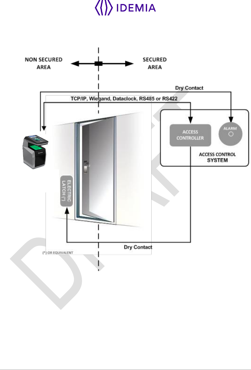
To secure properly an access, Idemia recommends installing the MorphoWave Compact terminal as a part
of the typical Access Control environment described in the figure below.
MorphoWave Compact
Terminal
Figure: Implementation Recommendations
This environment comprises:
The MorphoWave Compact terminal itself
Its role is to perform one-to-many biometric identification or one-to-one biometric verification, i.e. to identify
the individual who is presenting his finger on the terminal sensor by comparing his biometric data with the
references previously stored in the terminal database (in the form of biometric templates) or to verify his
identity using the reference stored in a contactless card presented to the terminal.
An Access Controller (3rd party product)
The Controller is the element which controls the access rights of the individuals to the secured area. For
that reason, it must be located in the secured area.

20
MorphoWave Compact - 2018_2000035853
The individuals who are authorized to access the secured area have their User ID listed in a so-called
"Authorized User List" (in contrast with a banned card list).
The MorphoWave Compact terminal and the Controller are communicating according to one of the TCP/IP,
Wiegand, Dataclock or RS485 protocols:
The MorphoWave Compact terminal sends User ID to the Controller
The Controller sends its decision to the MorphoWave Compact terminal (which displays access granted
or access denied depending on the answer)
The MorphoWave Compact terminal sends an alarm signal to the Controller as soon as a malicious
operation is detected (terminal pulled out from the wall or opened for maintenance operations); refer
the paragraph dealing with anti-pulling and anti-tamper switches for more explanations.
The Controller is part of the global Access Control System of the secured area, which can provide useful
features such as manage:
authorized user lists (i.e. for VIP),
banned card lists (i.e. for lost user cards),
an access request log (who and when, access granted or denied,..),
an event log (i.e. tamper detection, access control for evacuation of the building,...).
The MorphoWave Compact terminal is able to work alone, without Controller, but the protection level of
the secured area is lower.
An Alarm (3rd party product)
This element is connected to the MorphoWave Compact terminal through a dry contact.
The MorphoWave Compact terminal sends the command to activate the Alarm as soon as a malicious
operation (terminal pulled out from the wall or having its bottom cover opened out of maintenance
operations) is detected; refer the paragraph dealing with anti-pulling and anti-tamper switches for more
explanations.
A Door Electric Latch or equivalent (3rd party product)
This element once activated opens the access. The Controller is the one which sends the command to
activate the latch if access is granted (i.e. if the individual's User ID is listed in the Controller Authorized
User List). Connection between these two elements is done through a dry contact.

21
MorphoWave Compact - 2018_2000035853
2 / General description
22
MorphoWave Compact - 2018_2000035853
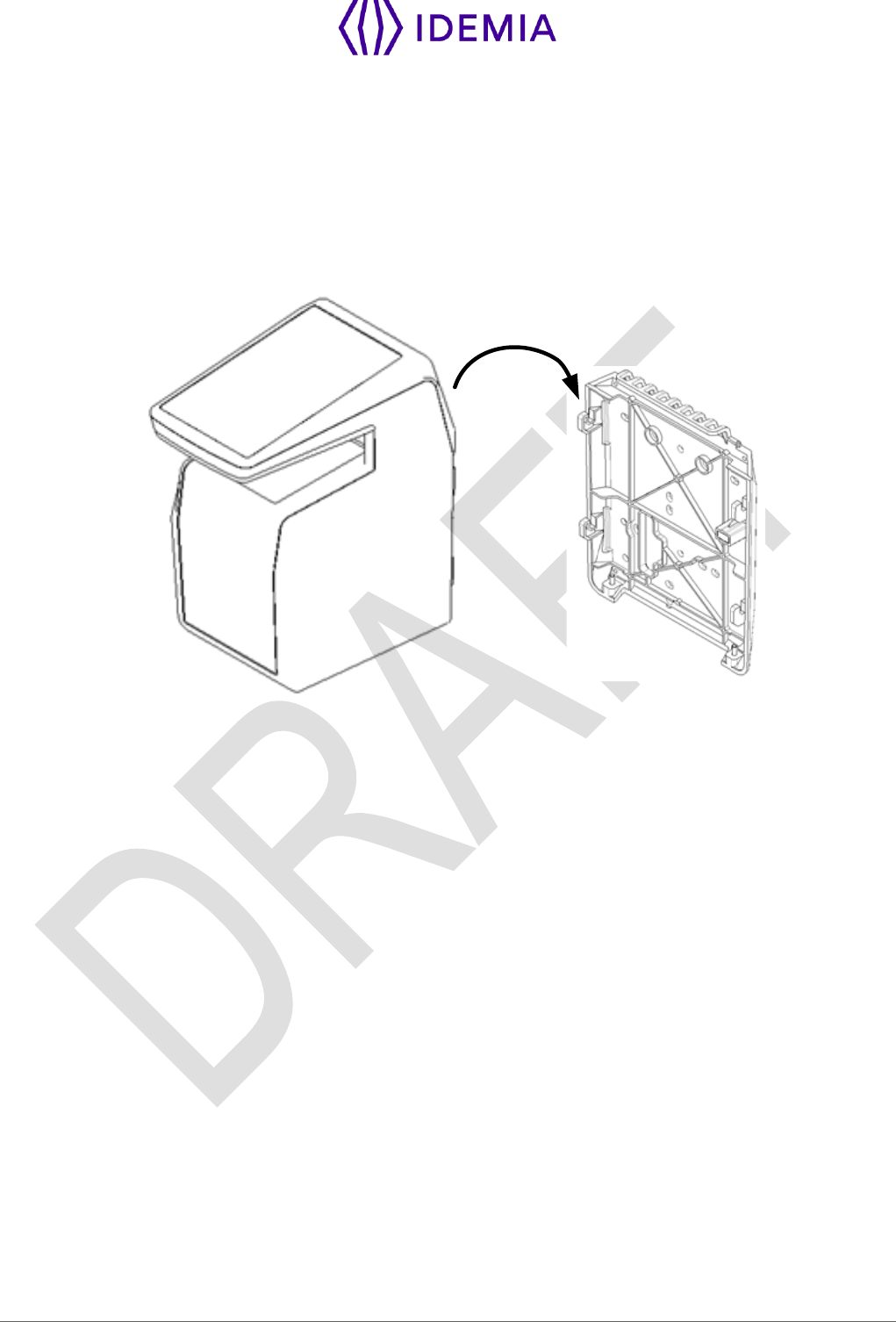
2.1 > Box opening
At the box opening, components shall be extracted from the protection casing as depicted in the pictures
below.
Extract the wall plate (which is not screwed to the terminal) and keep it separate until the installation of the
terminal is completed. The screwing of the product to the wall plate is the last stage of the installation.
Figure 1: Box Opening
23
MorphoWave Compact - 2018_2000035853
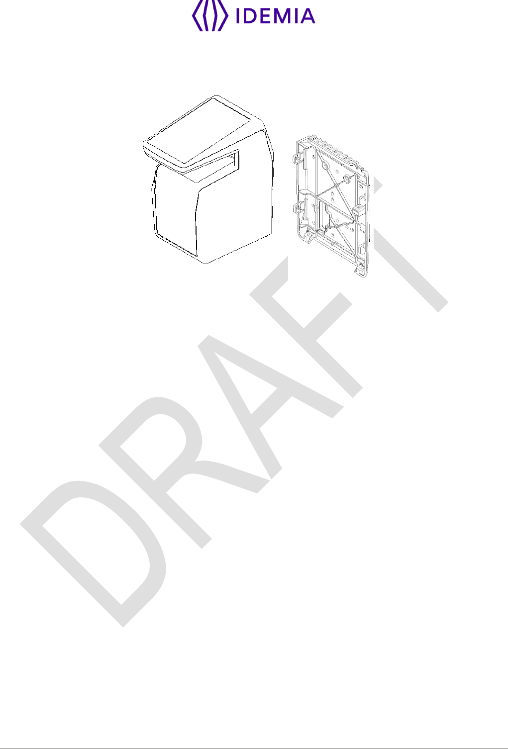
2.2 > Components of the initial package
Figure 2: Box Content
1. One (1) Terminal’s body
2. One (1) Wall frame
25
MorphoWave Compact - 2018_2000035853
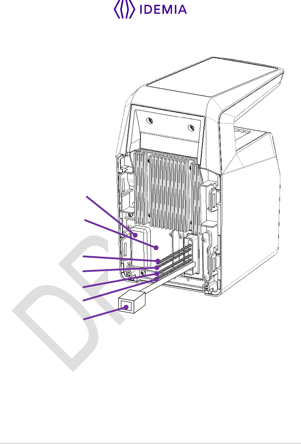
2.4 > Terminal's rear view description
RJ45
Power supply, Relay,
Tamper switch
GPIO
RS485 / RS422
Wiegand
USB port (for
configuration and
settings with a USB
mass storage key, or
for installation of a
Wi-Fi™ USB dongle)
SAM card (option)
Figure 4: MorphoWave Compact terminal rear view
26
MorphoWave Compact - 2018_2000035853
2.5 > MorphoWave Compact Technical Characteristics
Item
Description
Access control modes
Identification (search for fingerprints in a local database)
Authentication with contactless smartcard, with or without
fingerprint check
Multi-factor: identification or authentication (only if terminal is
equipped with a contactless smartcard reader)
Proxy: the access control check is fully driven by a remote
system
Man Machine Interface
4.3” WVGA color capacitive Touchscreen
Powerful Loudspeaker & Microphone
Biometrics
Hand swipe through the active volume without contact:
40 x 25 x 80 mm (WxHxD) capture volume
(1.57’’ x 0.98’’ x 3.14’’)
500dpi, 256 gray levels optical sensor
0.5 m/s (19.7 in/s) maximum hand speed
Up to 4 fingers capture capacity per swipe motion
False Acceptance Rate (FAR) adjustable from 1% down to 10-
7%
Database capacity: 20,000 users (standard) and up to 100 000
users (with specific license)
Log capacity
1 000 000
LAN/WLAN connection
For terminal configuration and data transfer:
Ethernet 10/100 Base T (MDI, MDI-X)
Or Wi-Fi™ Wireless LAN (option), WEP, WPA (PSK) and
WPA2 (PSK) encryption available
Either TCP, SSL or TLS protocol
MIFARE Classic 1KB & 4KB (4b and 7b UID)
27
MorphoWave Compact - 2018_2000035853
RFID cards (depending
on product version)
MIFARE Plus SL1 cards
DESFire 3DES legacy 2K, 4K and 8K (EV0 & EV1)
DESFire AES 2k, 4k, 8k (EV1)
All HID iClass cards (incl. iClass legacy, iClass SR and iClass
SE), except 2K2
HID Prox 125 kHz whatever the format (26, 37 ....)
Serial port
The serial port supports WIEGAND, DATACLOCK (ISO2),
RS422 and RS485 protocols
GPIO
3 GPI, 3 GPO
Output relay switches
Access granted: 1 switch two outputs (normally “open” and
normally “closed”)
30V – 1A max (Resistive loads, 100 000 cycles)
USB host port
terminal configuration through a USB mass storage key
connection with an external Wi-Fi™ USB dongle using an
adapter cable
Input signals
LED1/LED2 to activate the access granted relay
Power supply
12 to 24 V DC power supply (2.5A min @12V)
Or by Power Over Ethernet through RJ-45 connector
Note for UL 294 Compliance power supply shall be UL 294 and
UL 294B with power limited output
Security of the terminal
Anti-tamper-pulling switches
Tamper-pulling detection: one switch closed when product wall
mounted, open when pulled out
Size and weight
W x H x D: 152 mm x 250 mm x 220 mm
(6.98” x 9.84” x 8.66”)
Weight : ~ 2 kg
Environmental
conditions
Operating temperature:
-10 °C to + 55 °C (14°F to 131°F) when ECO-mode is ON
28
MorphoWave Compact - 2018_2000035853
-10 °C to + 45 °C (14°F to 113°F) when ECO-mode is OFF
Operating humidity 10 % < RH < 80 % (non condensing)
Storage temperature -25 °C to + 70 °C (-13°F to 158°F)
Storage humidity 5% < RH < 95 %
The terminal should be installed in controlled lighting conditions
Avoid direct exposure to sunlight or to UV lights
Certification planned
CE, IEC 60950-1, FCC Part 15, RSS210 - Issue 8 : 2010,
RSS-102 - Issue 5 : 2015, RSS-Gen – Issue : 2014, RoHS,
REACh, WEEE

29
MorphoWave Compact - 2018_2000035853
3 / Installation procedure
30
MorphoWave Compact - 2018_2000035853
3.1 > Before proceeding to the installation
Make sure that you have all the components described in “Components of the initial package” section
at your disposal.
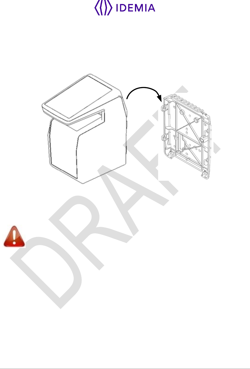
Remove the wall plate. Keep this element at hand.
Figure 5: Removing wall frame
It is then possible to fix the terminal on the wall.
For an optimal use the terminal must be installed in an area where the lighting conditions
are controlled. Avoid direct exposure of the sensor to the sun light and ensure good ambient
lighting for face detection if used.

31
MorphoWave Compact - 2018_2000035853
3.2 > Installation
Required tools (not supplied)
Four (4) raw plugs + four (4) screws ø4mm max and length adapted to the wall material.
One (1) screwdriver adapted to screws above.
One (1) Drill (with a drill bit diameter adapted to raw plugs above).
One (1) hole saw (depending on installation case).
A (1) CHC H2 screwdriver
A (1) CHC H2.5 screwdriver
Deadbolt/door strike
Snubber diode required to protect regulated DC power supply from inductive kickback (1N4007 diode
or equivalent recommended)
Separate power supply for the deadbolt/door strike based on supplier's recommendations.
External relay (if required)
Networking cable
For UL-294 compliance, an earthed screen in the wire or around all wires to/from product is only required
when the wires share space/compartment/tube with high voltage cables.
Equipment from the initial package to use
One (1) Terminal’s body.
One (1) wall plate.
32
MorphoWave Compact - 2018_2000035853
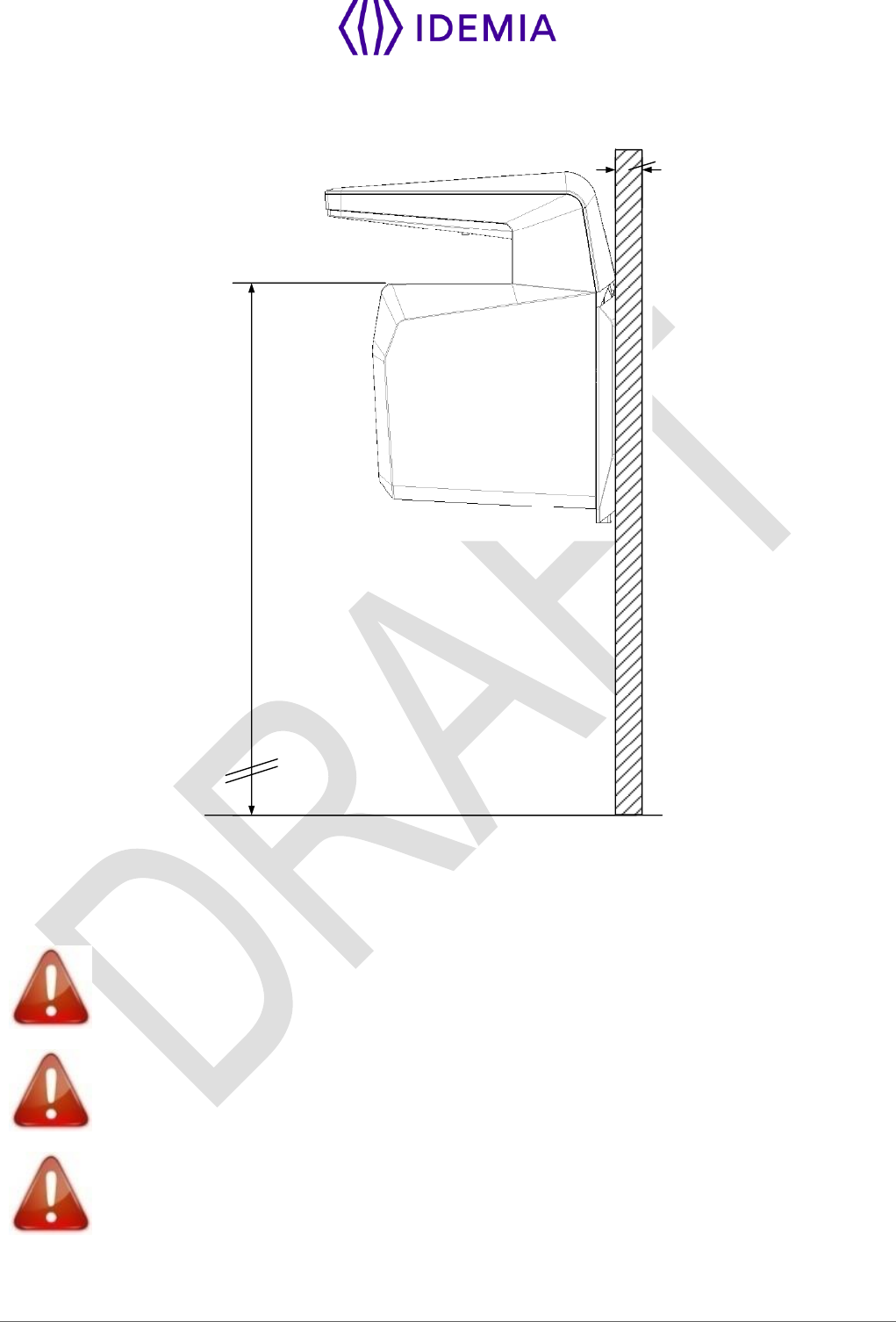
3.3 > Step by step procedure
1050 to 1150 mm
Floor
Wall
40 min
Figure 6: Face camera viewing angle
The recommended height for fixing of the terminal is 1.05 to 1.15 m (height of the acquisition glass).
For an optimal use the terminal must be installed in an area where the lighting conditions
are controlled. Avoid direct exposure of the sensor to the sun light.
Power supply from electrical source shall be switched off before starting the installation.
The strength of the attachment depends on the solidity of the wall on which the terminal is
mounted.
33
MorphoWave Compact - 2018_2000035853
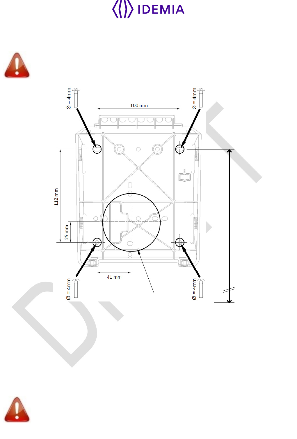
3.3.1 > Drill the mounting holes
Be sure that the wall behind the wall plate has a good flatness.
1020 to 1120 mm
Recommended mounting
height from the floor
Floor
Ø 67 mm
Depth ≥ 40 mm
Figure 7: Drilling template
If not present, drill in the wall a hole with a diameter adapted to the width of the terminal and the cable to
be hosted in (see Figure 7: Drilling template. This template can be found in the Quick Installation Guide).
The 67 mm diameter hole (cf. drilling template) should be at least 40 mm deep in order to fit the connections
and cables. A deeper hole is recommended is possible, to make the connection process easier.
Confirm the presence inside the hole of all the cables needed for the electrical installation (see Erreur !
Source du renvoi introuvable.)
Drill in the wall 4 holes with a diameter adapted to screws and fit them with the raw plugs (see Figure 7:
Drilling template).
Be sure that a sufficient space is reserved in the wall for the passage of cables, in
particular for Ethernet.
34
MorphoWave Compact - 2018_2000035853
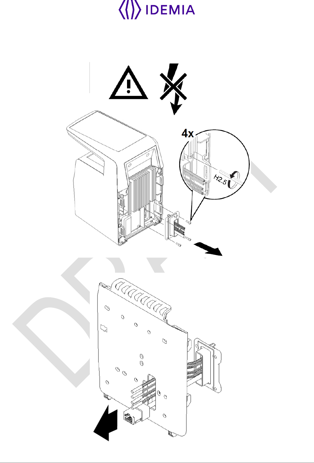
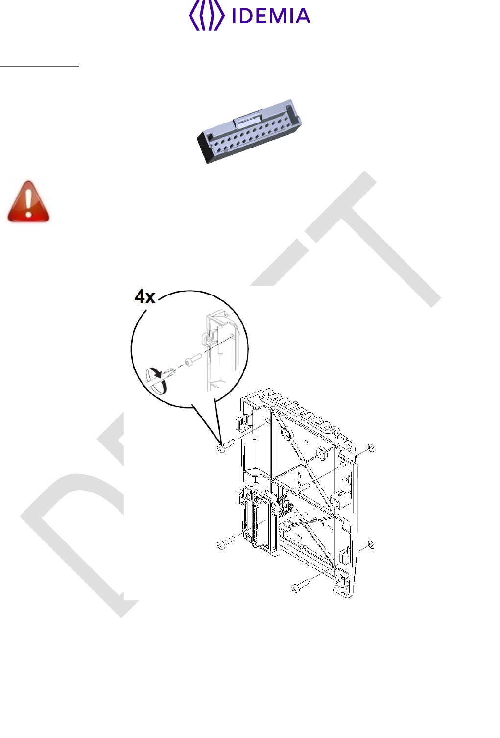
3.3.2 > Make the connections
Unscrew the connector from the device:
Fit the cables through the mounting plate:
35
MorphoWave Compact - 2018_2000035853
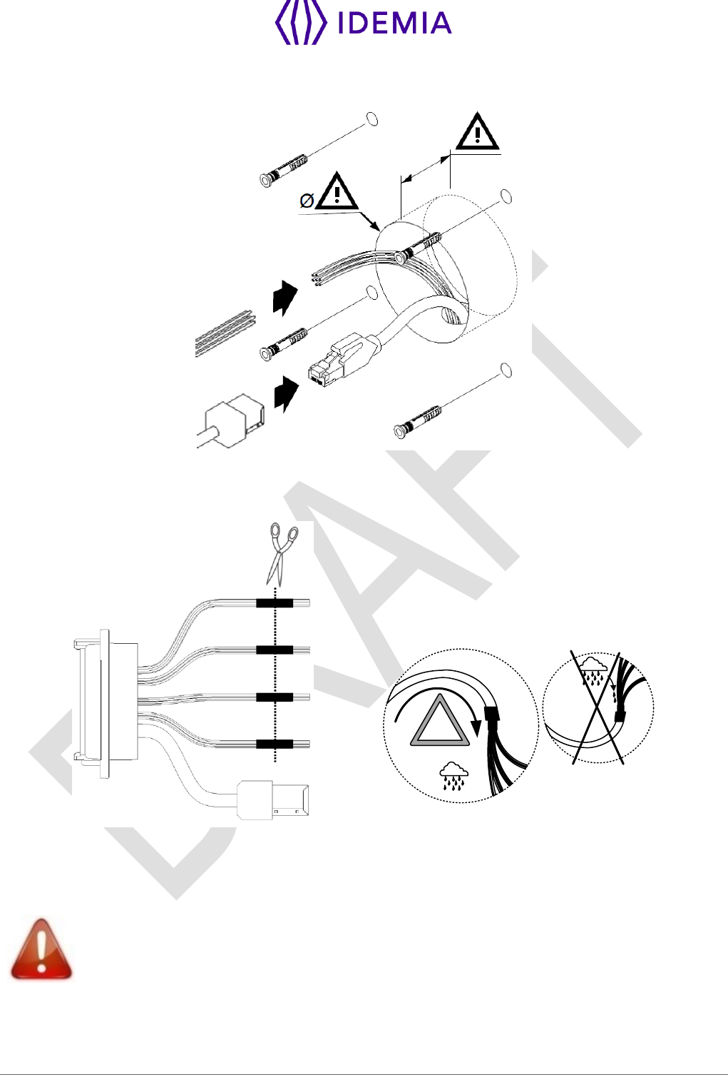
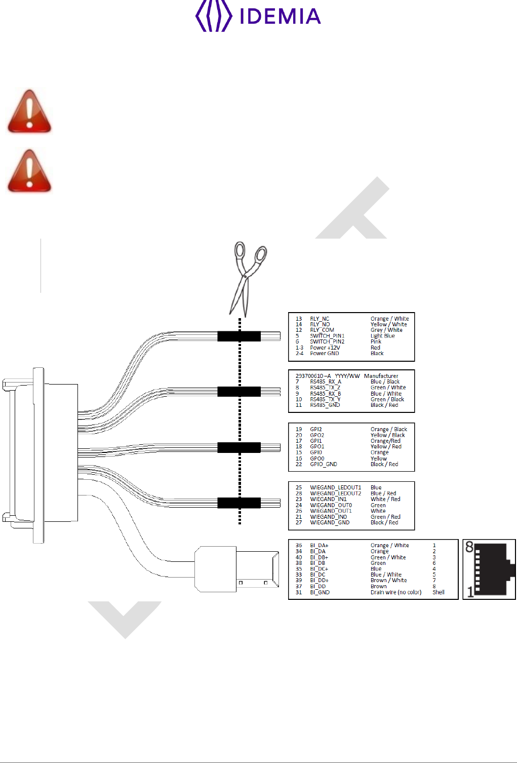
Then connect the cables:
Before cabling the product, remove the connector by cutting cables in the middle of heat shrink tube.
Please refer to section 4 / for explanations of how cables/wires should be connected, according to wire
color code.
IP65
!
Figure 8: Cable preparation : cable position for water tightness
Cable for wiring shall be AWG 20 to 24, length shall be adapted to the size of the hole in the wall, to
terminal connections, and to the distance between the electric source and the terminal itself.
To ensure water tightness, be sure to bend the cable downward.
36
MorphoWave Compact - 2018_2000035853
For test purpose, it is possible to use the existing connector without cutting it. This connector mates with
Molex PCB header reference 5016452620. The pinout of this connector is described in this document in
section 4 /.
The pinout indications that you can see on the labels of the cable shall NOT be taken into
account as they correspond to the OTHER connector on the device side. Please use only
the pinout information given in this document in section 4 /.
3.3.3 > Attach the base plate on the wall
Fix the base plate on the wall with the 4 screws.
37
MorphoWave Compact - 2018_2000035853
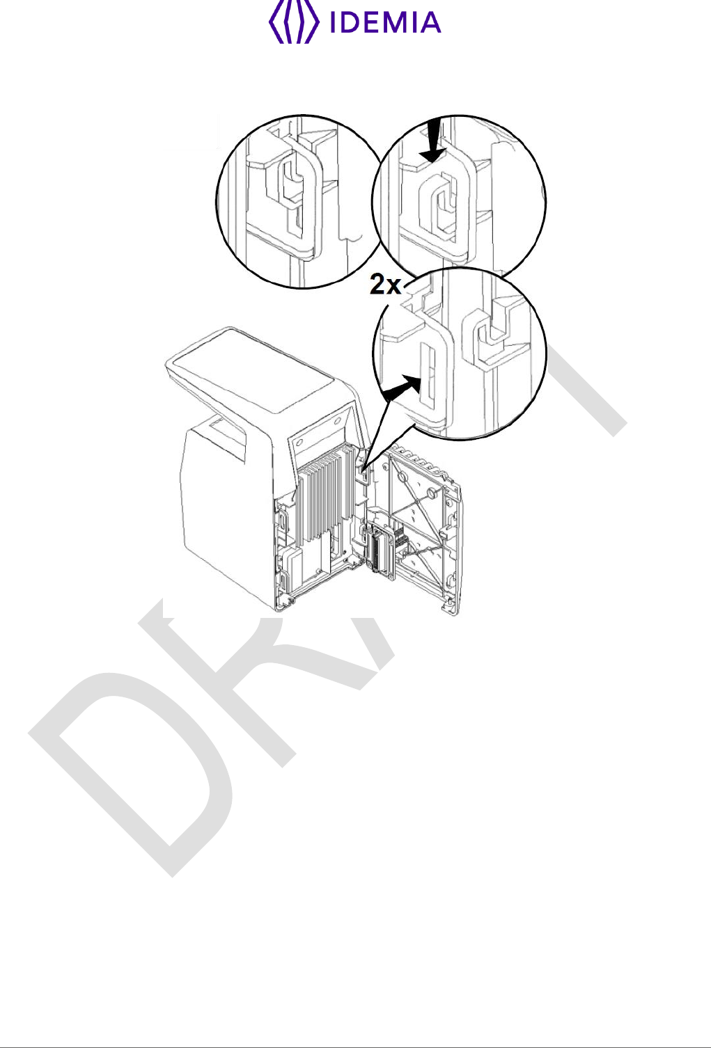
3.3.4 > Attach the device on the base plate
38
MorphoWave Compact - 2018_2000035853
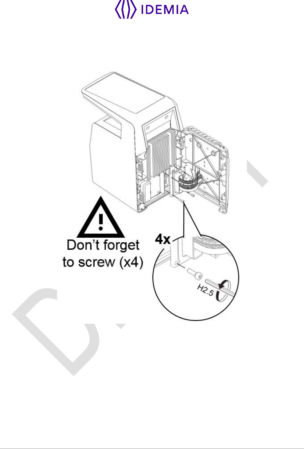
3.3.5 > Connect the connector assembly on the device
Attach the connector assembly on the device with the 4 screws.
39
MorphoWave Compact - 2018_2000035853
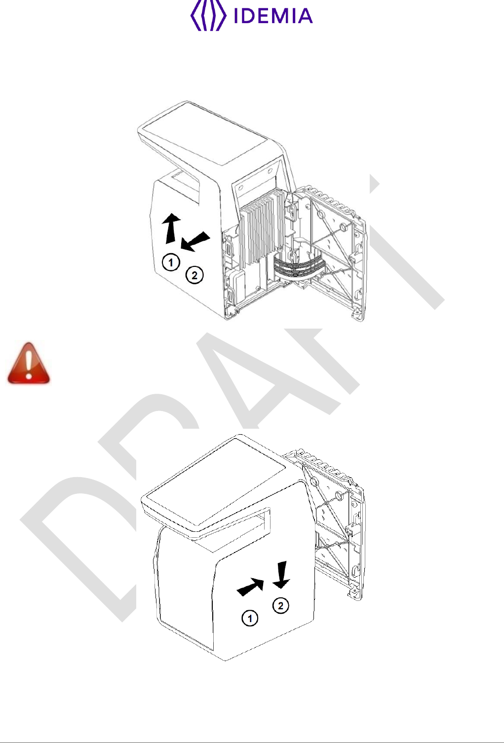
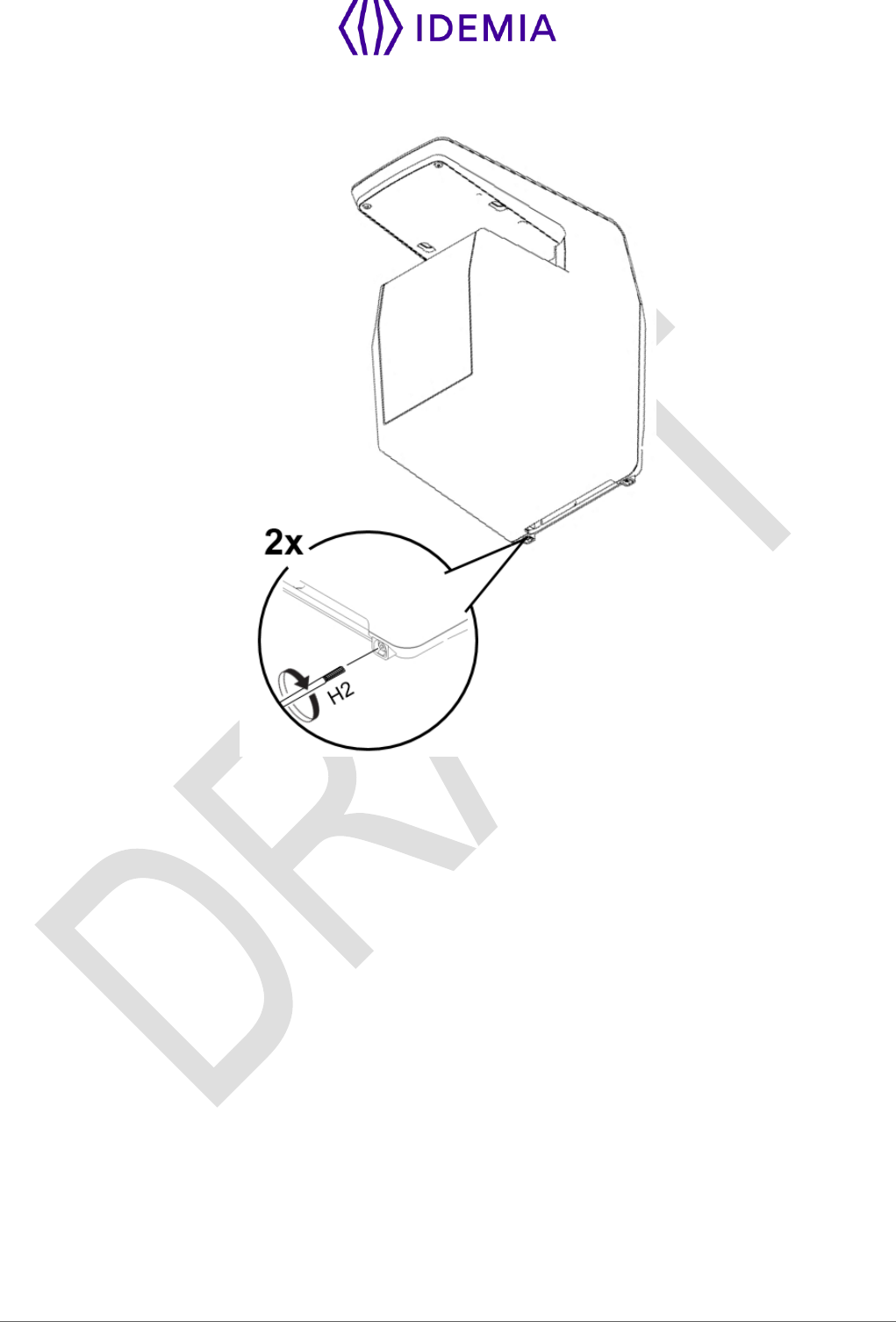
3.3.6 > Close the device on the base plate
Detach the device from the plate: first lift the device upwards, then pull it towards you, and hold it.
Do not try to turn the product directly while it is attached on the base plate, as this would
definitely damage the plate and the device !
Then rotate the device 90° to align it in the final position in front of the plate. Push the device towards the
wall, then downwards until the device is locked on the plate.
40
MorphoWave Compact - 2018_2000035853
Then to secure the device on the plate, attach the last screw on the bottom of the device:
The hardware installation of the product on the wall is complete !
Power can be switched ON just after closing it. If the product has to be stored for a long time (more than
48 hours), don’t forget to restore its configuration before use.

41
MorphoWave Compact - 2018_2000035853
4 / Electrical interface
42
MorphoWave Compact - 2018_2000035853
4.1 > Wiring overview
Before proceeding, make sure that the person in charge of installation and connections is
properly connected to earth, in order to prevent Electrostatic Discharges (ESD).
Power supply ground shall not be used for peripheral ground. All other grounds can be
used indifferently.
Note that all connections of the MorphoWave Compact terminal described hereafter are of SELV (Safety
Electrical Low Voltage) type.
Figure 9: Cabling layout
43
MorphoWave Compact - 2018_2000035853
4.2 > Power Supply
PoE+ and external power supply are not used at the same time: if both power supplies are used, priority
is given to external power supply. If external power supply is shut down, switch to PoE+ without reboot is
not guarantee.
External Power supply
Figure 10: Power supply wiring
1-3
Red
Power Supply 12-24V DC
In
Positive 12-24 Volts, power supply
2-4
Black
Power ground
In
Ground power supply
The External power supply
Must comply with IEC 60950-1 standard marked Class 2, Limited Power source (LPS)
12V to 24V Dc (regulated and filtered) 2.5 Amp min at 12V.
If sharing power between devices, each unit must receive 2.5A (e.g. two units would require a 12vDC,
5A supply).
IDEMIA recommends using a 24V power supply and AWG16 gauge cable. The voltage measured on the
product block connector of the terminal must be equal to 12V-24V (-15% / +10%).
The voltage drop due to the cable shall be taken into account. The table below shows as an example the
maximum distance between power supply and one (1) unique device, depending on cable gauge and
power supply rating.
Gauge
AWG
Section
(mm2)
Maximum distance (meters)
vs power source rating
12V+/-10%
12V+/-5%
24V+/-10%
16
1.31
9 m
20 m
300 m
18
0.82
6 m
12 m
200 m
20
0.52
3 m
8 m
120 m
22
0.32
2 m
5 m
75 m
If several terminals are powered by the same cable, make sure to select a wire gauge that
complies with maximum voltage drop, cable length, and power source minimum voltage
rating.

44
MorphoWave Compact - 2018_2000035853
PoE+ (Power over Ethernet Plus)
MorphoWave Compact terminal's power supply can also be provided by the Ethernet using RJ45 connection
(Power over Ethernet Plus mode - IEEE802.3at type 2 compliant).
The terminal may be powered via a UL 294B PSE PoE+ Limited power source with a range of 48VDC (-
10% /+15%). UL 294 compliance was verified with PoE+ (PSE-Power Sourcing Equipment manufacturer
Microsemi, part number PowerDsine 9501G).
If several terminals are powered through the same PoE+ switch, make sure the switch is
capable of providing enough power to each device (25W).
Some functions are available ONLY with an external and not with PoE power supply: Wi-
Fi, SAM, PIV/TWIC. External DC power is required for these features.
45
MorphoWave Compact - 2018_2000035853
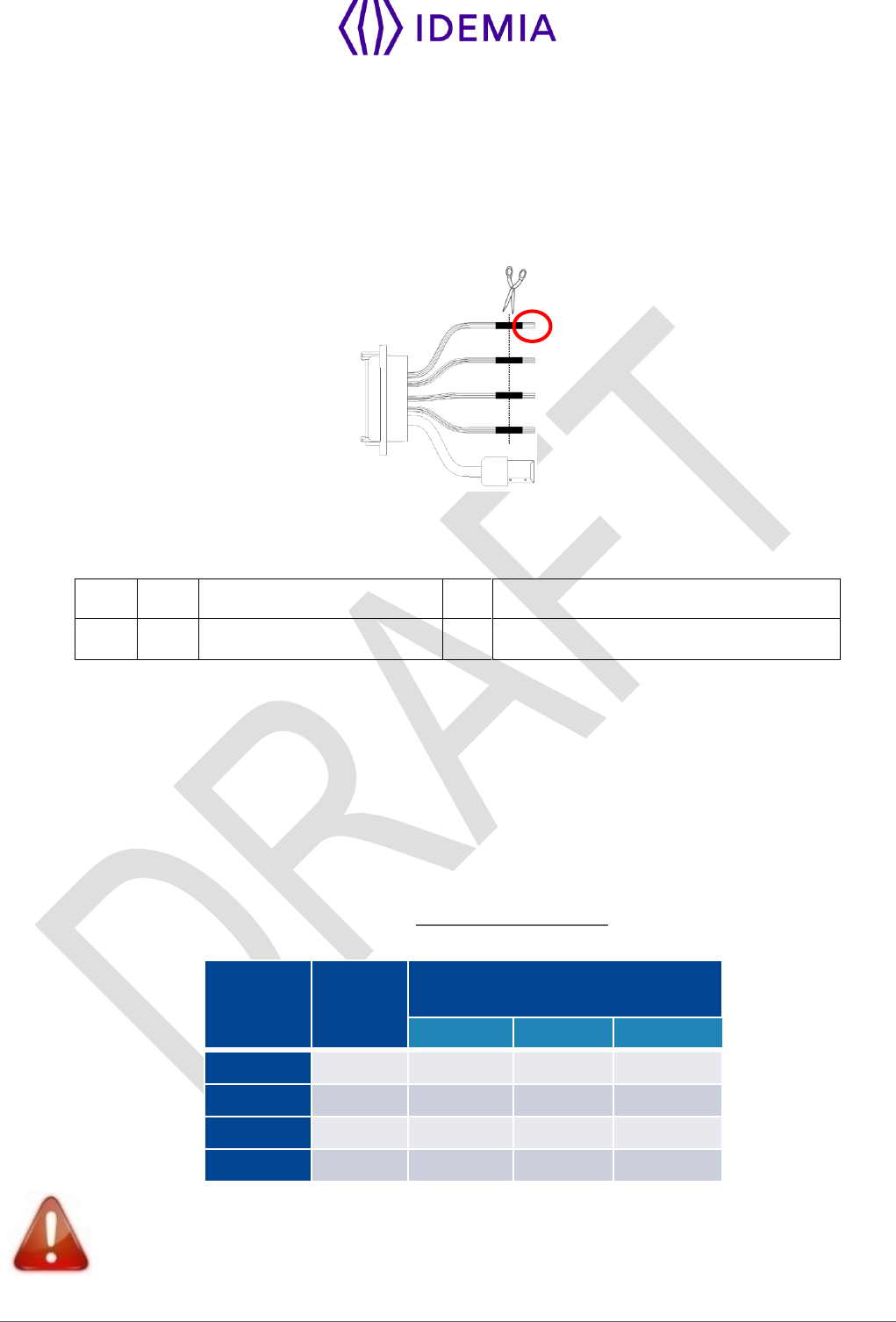
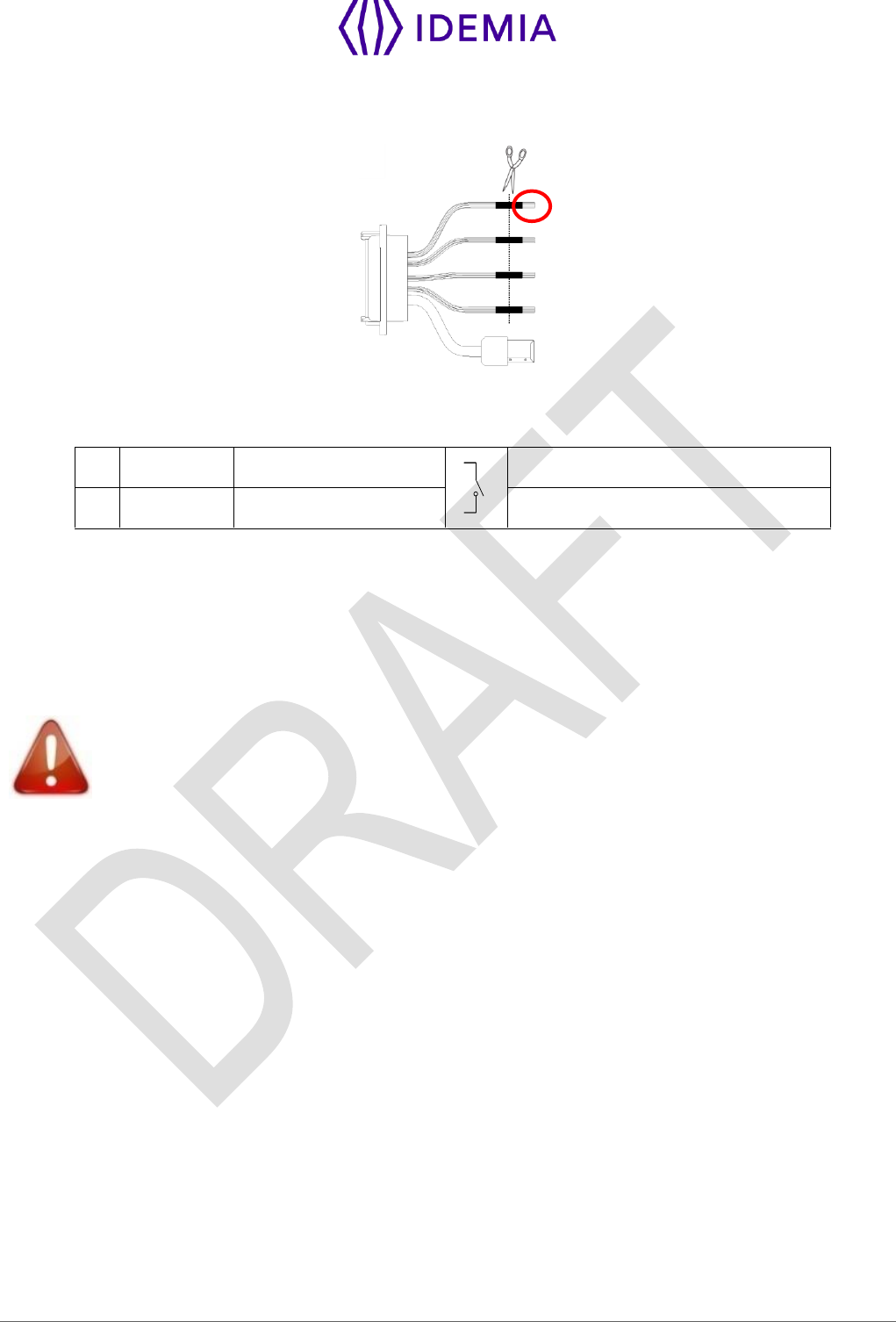
4.3 > Output Relay
Figure 11: Output relay wiring
14
Yellow / White
RLY_NO
Contact relay (normally open)
12
Grey / White
RLY_COM
Contact relay common
13
Orange / White
RLY_NC
Contact relay (normally closed)
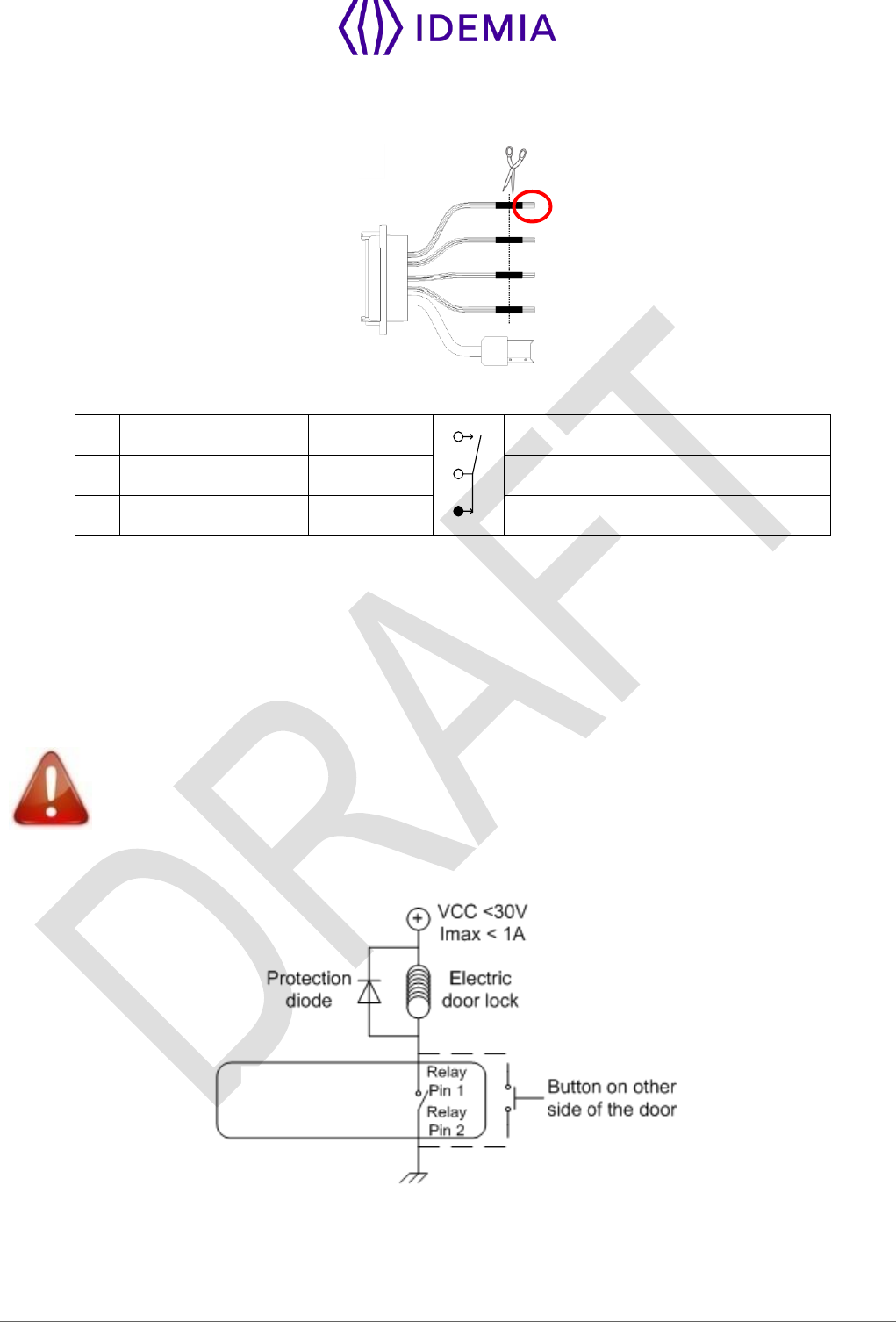
Nominal characteristics of relay
Load characteristics:
1 A max @ 30 VDC (according to the safety extra low voltage requirements independently of the power
supply),
Resistive load or inductive load; see warning information hereafter for inductive load,
The internal relay is designed for at least 100 000 cycles (resistive load).
Inductive load management requires a parallel diode for a better contact lifetime.
Example of connection for electrical door locks
MorphoWave
Compact terminal
Figure 12: Example of electric latch connection
46
MorphoWave Compact - 2018_2000035853
4.4 > Tamper Switch
Figure 13: Tamper switch wiring
5
Light Blue
SWITCH_PIN1
Tamper switch contact
6
Pink
SWITCH_PIN2
Strip on tamper switch
Operating principle for the switch
Product installed on the wall plate: switch enabled (contact closed).
Product opened (rear connectors accessible): switch disabled (contact open).
Nominal characteristics of switch block
100 mA at 30 VDC max (Resistive load) according to the safety extra low voltage standard.
This MorphoWave Compact terminal is part of security system; it is customer’s responsibility
to connect the tamper switch (contact) to physical access controller, in order to prevent the
access to the connector blocks.
47
MorphoWave Compact - 2018_2000035853
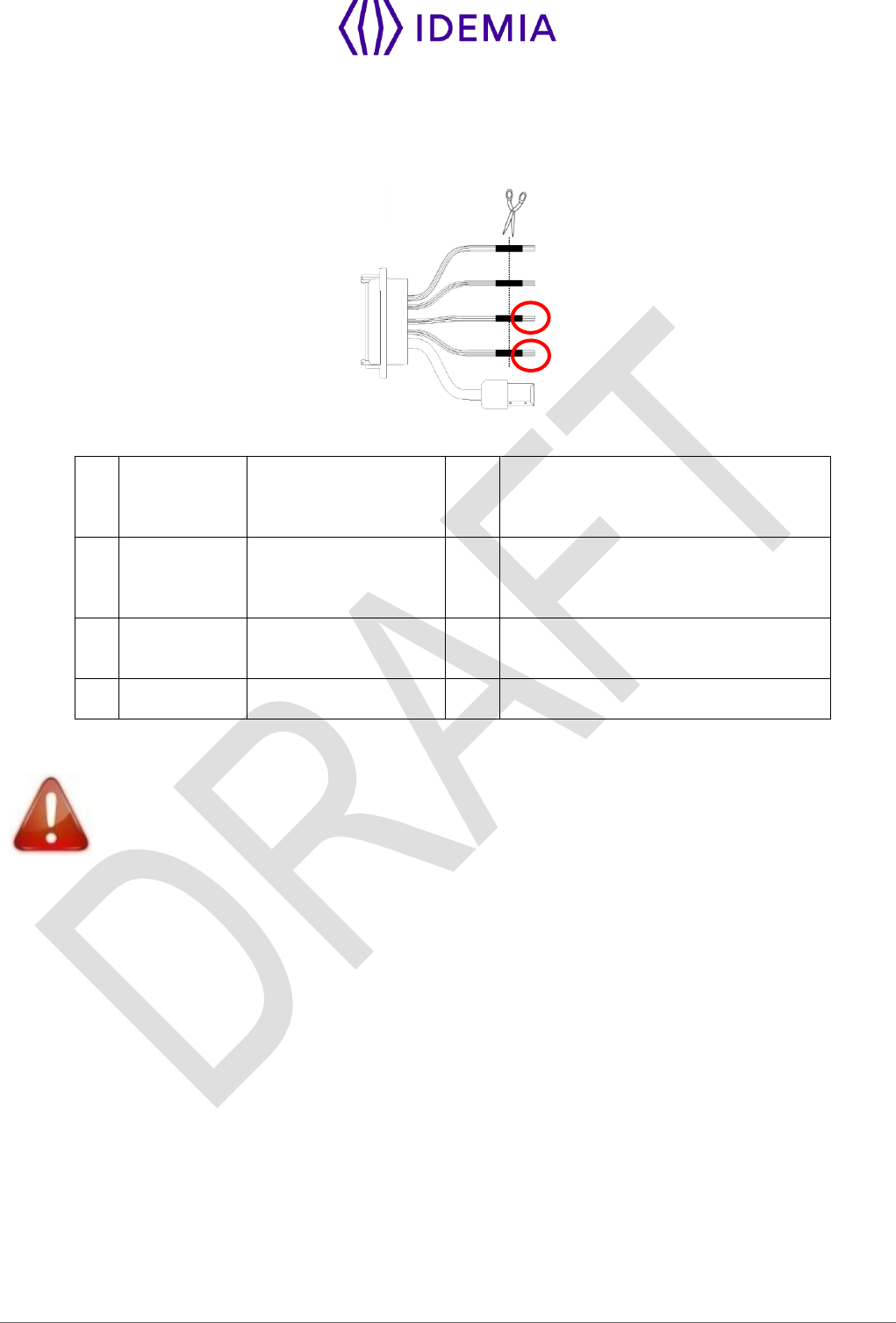
4.5 > Wiegand wiring
Wiegand input
Figure 14: Wiegand input wiring
21
Green / Red
WIEGAND_IN0
In
Wiegand IN D0
(Output type required: Open drain or
5V+/-5%)
23
White / Red
WIEGAND_IN1
In
Wiegand IN D1
(Output type required: Open drain or
5V+/-5%)
16
Yellow
GPO0
Out
Wiegand LEDIN (typical = 5VDC)
(option)
27
Black / Red
WIEGAND_GND
Ground for Wiegand
If pull-up’s to 12V have been added on Wiegand IN D0 and Wiegand IN D1 inputs on a
previous installation with a MorphoAccess® 500 Series terminal, these resistors must be
removed to avoid any damage to the MorphoWave Compact terminal.
48
MorphoWave Compact - 2018_2000035853
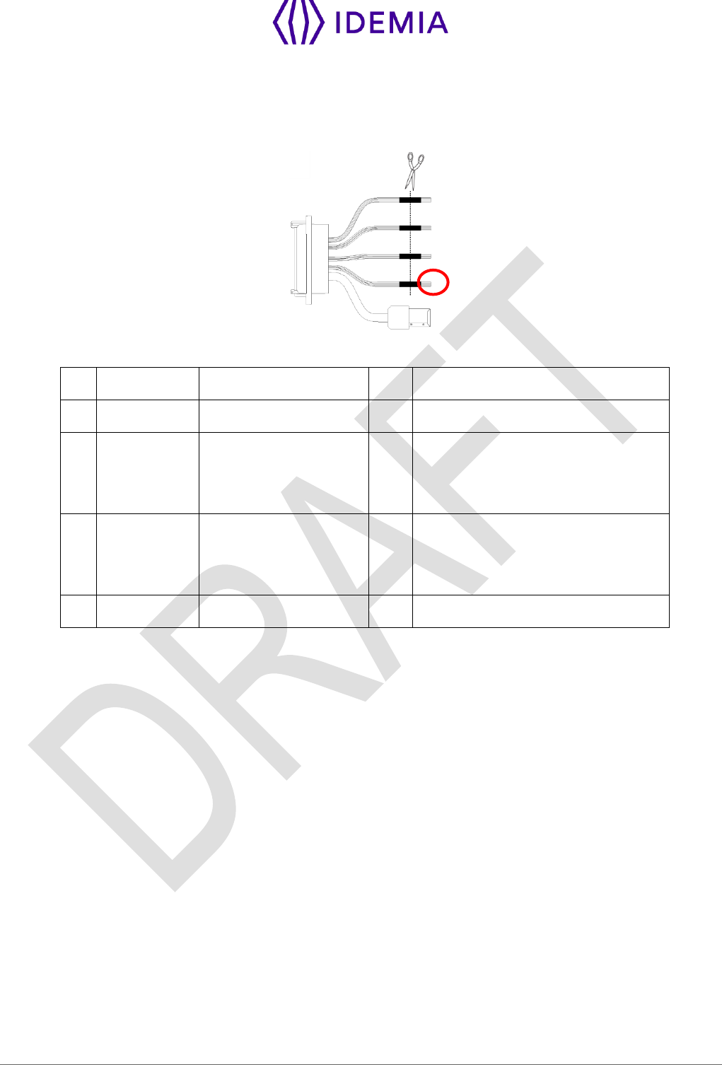
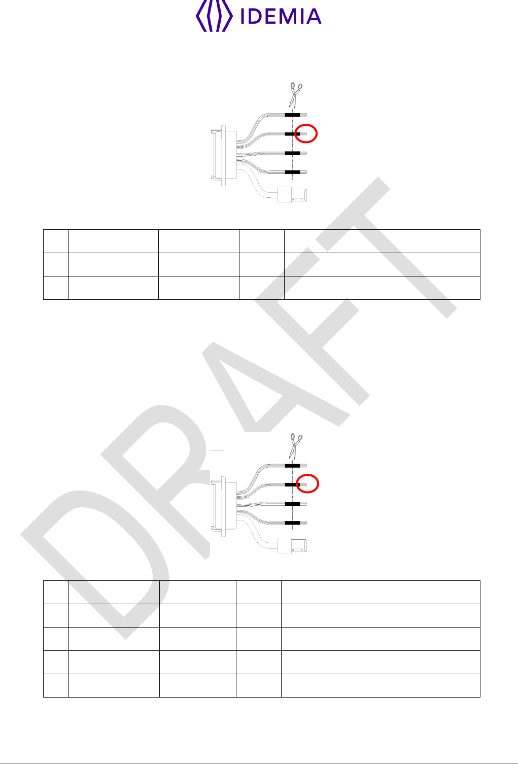
4.6 > Wiegand output
The following figure shows how to cable the wires of the serial port of the terminal for the Wiegand protocol
Figure 15: Wiegand output wiring
24
Green
WIEGAND _OUT0
Out
Wiegand OUT D0 (5V TTL)
26
White
WIEGAND _OUT1
Out
Wiegand OUT D1 (5V TTL)
25
Blue
WIEGAND_LEDOUT1
In
Wiegand LED IN 1 (option): panel
feedback
(Output type required: Open drain or
5V+/-5%)
28
Blue / Red
WIEGAND_LEDOUT2
In
Wiegand LED IN 2 (option): panel
feedback
(Output type required: Open drain or
5V+/-5%)
27
Black / Red
WIEGAND_GND
Ground for Wiegand
The use of LED1 and LED2 wires is described in the paragraphs below.
The controller supports neither LED1 nor LED2 signals
When the access controller has no relay contact to provide an answer to the MorphoWave Compact
terminal, then the decision to emit either the “access granted” signal or the “access denied” signal is taken
by another way. It is either the MorphoWave Compact terminal itself that decide, or it waits for the access
controller answer through the local area network (TCP), or on the serial port in (RS485 or RS422).
It is strongly recommended to disable the LED IN feature, to avoid any interference on MorphoWave
Compact terminal behavior.
The controller supports only LED1 signal
When the access controller has only one relay contact which is dedicated to the “access granted” answer,
this one must be connected between the LED1 and GND wires. The LED1 wire is set to the low level by
closing the contact between the LED1 and the GND wires, and it means “access granted”.
The MorphoWave Compact terminal uses the timeout of the wait for a low level on the on LED1 wire or
LED2 wire as “access denied” answer.
To minimize at most the waiting time of the user, the MorphoWave Compact terminal timeout value, must
be adjusted to a value a little bit higher than the maximal value of the controller response time.
Warning: if the LED2 wire is connected, it must be constantly maintained in the high state.

49
MorphoWave Compact - 2018_2000035853
The controller supports LED1 and LED2 signals
When the controller supports one relay contact for each of the possible answers then:
The « access granted » contact must be connected between the LED1 and the GND wires of the
terminal
The « access denied » contact must be connected between the LED2 and the GND wires of the
terminal.
The MorphoWave Compact terminal considers that:
The answer of the controller is "access granted", when the controller puts the LED1 wire to the low
state (by closing a contact between the LED1 and the GND wires), and leaves the LED2 wire to the
high state.
The answer of the controller is "access denied", when the controller puts the LED2 wire to the low state
(by closing a contact between the LED2 and the GND wires), whatever is the state of the LED1 wire.
The MorphoWave Compact terminal also considers that the answer of the controller is "access denied" in
case of time-out while expecting for a closure between LED1 and GND wires, or between LED2 and GND
wires.
50
MorphoWave Compact - 2018_2000035853
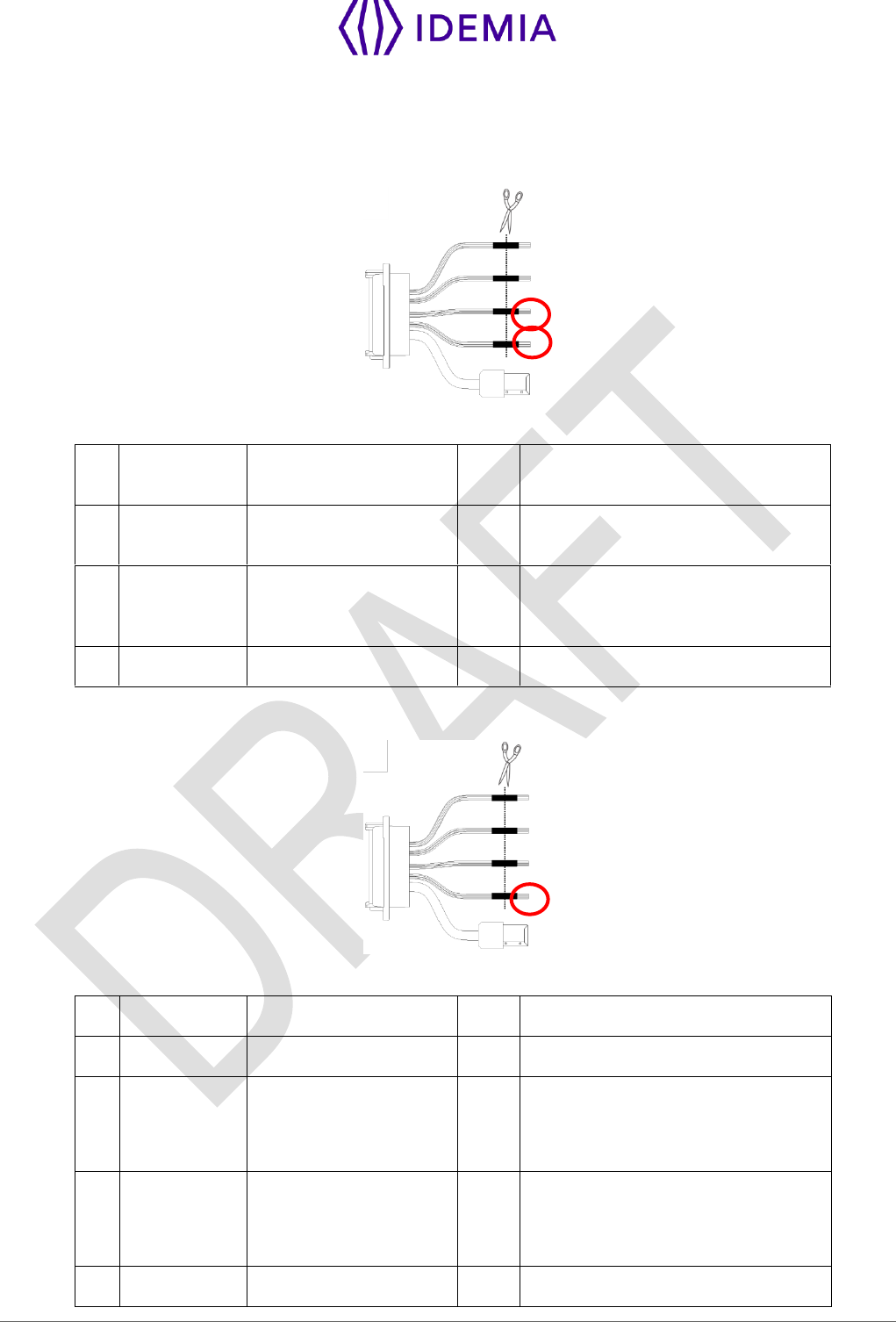
4.7 > Serial port wiring
DataClock Input
Figure 16: Serial port wiring – DataClock Input
21
Green / Red
WIEGAND_IN0
In
Data (Output type required: Open
drain only)
23
White / Red
WIEGAND_IN1
In
Clock (Output type required: Open
drain only)
16
Yellow
GPO0
Out
Card present signal (if configured,
only one selectable for Morpho
Legacy)
27
Black / Red
WIEGAND_GND
Ground for Wiegand
DataClock Output
Figure 17: Serial port wiring – DataClock Output
24
Green
WIEGAND _OUT0
Out
Data ( 5V TTL )
26
White
WIEGAND _OUT1
Out
Clock ( 5V TTL )
25
Blue
WIEGAND_LEDOUT1
In
LED IN 1 (option): panel feedback
(Output type required: Open drain or
5V+/-5%)
28
Blue / Red
WIEGAND_LEDOUT2
In
LED IN 2 (option): panel feedback
(Output type required: Open drain or
5V+/-5%)
27
Black / Red
WIEGAND_GND
Ground for Wiegand
51
MorphoWave Compact - 2018_2000035853
RS485
Figure 18: Serial port wiring – RS485
7
Blue / Black
RS485_RX_A
In/Out
RS485 Rx/Tx non inverting signal
9
Blue / White
RS485_RX_B
In/Out
RS485 Rx/Tx inverting signal
11
Black / Red
RS485_GND
Ground
RS485 implementation is limited to half-duplex communication. So only Tx+, Tx- and ground reference
signals are necessary.
Depending on the RS485 network, an impedance adaptation may be required.
For farthest terminal, a 120-Ohms resistor termination may be added outside the terminal between TX+
and TX-.
RS422
Figure 19: Serial port wiring – RS422
7
Blue / Black
RS485_RX_A
In
RS422 non inverting Receive
9
Blue / White
RS485_RX_B
In
RS422 inverting Receive
10
Green / Black
RS485_TX_Y
Out
RS422 non inverting Transmit
8
Green / White
RS485_TX_Z
Out
RS422 inverting Transmit
11
Black / Red
RS485_GND
Ground
RS422 interface is a full duplex communication.
52
MorphoWave Compact - 2018_2000035853
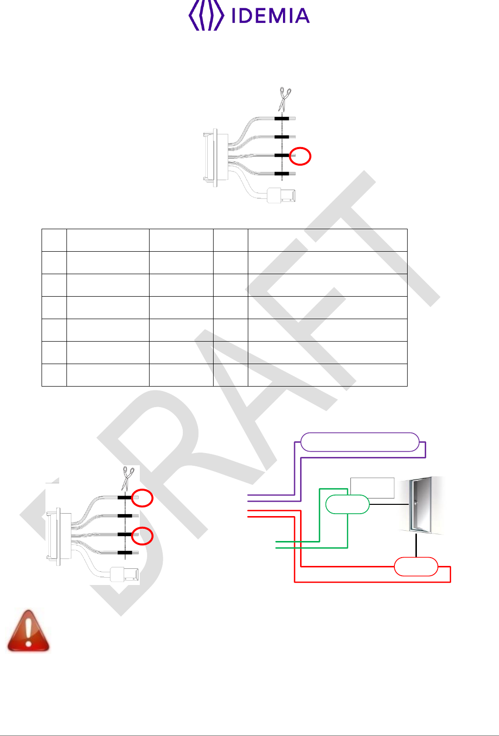
4.8 > GPIO wiring
Figure 20: GPIO wiring
19
Orange / Black
GPI2
In
Digital Input (1,8V to 5V)
20
Yellow / Black
GPO2
Out
Digital Output (5V – 5mA max)
17
Orange / Red
GPI1
In
Digital Input (1,8V to 5V)
18
Yellow / Red
GPO1
Out
Digital Output (5V – 5mA max)
15
Orange
GPI0
In
Digital Input (1,8V to 5V)
16
Yellow
GPO0
Out
Digital Output (5V – 5mA max)
22
Black / Red
GPIO_GND
Ground
Single Door Access Control (SDAC) implementation
Figure 21: SDAC wiring
If door contact is not used, GPI1 and GPO1 shall be connected together
External Power
supply
GPI_1
GPO_0
Push button /
Motion sensor
GPI_0
GPO_1
RELAY_COM
RELAY_NO/NC
Door
contact
Door
strike
53
MorphoWave Compact - 2018_2000035853
4.9 > Ethernet connection
Use a category 6 shielding cable (120 Ohms) or better. It is strongly recommended to insert a repeater
unit every 90 m.
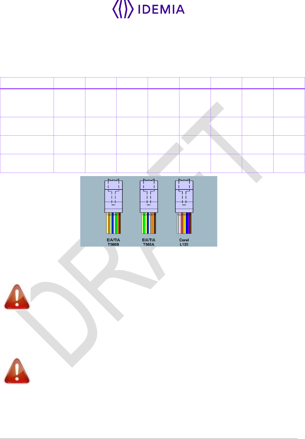
Recommendations for RJ45 wiring
Pin
1
2
3
4
5
6
7
8
Signals
Data
pair 1
Data
pair 1
Data
pair 2
NC/POE
pin
dedicated
(+)
NC/POE
pin
dedicated
(+)
Data
pair 2
Ground/
pin
dedicated
(-)
NC/POE
pin
dedicated
(-)
EIA / TIA T568B
Colors
White
orange
Orange
White
green
Blue
White blue
Green
White
brown
Brown
EIA / TIA T568A
Colors
White
green
White
green
White
green
White
green
White
green
White
green
White
green
White
green
Corel L120
Colors
Grey
White
Pink
Orange
Yellow
Blue
Purple
Brown
Figure 22: RJ45 wiring
RJ45 plug pinout is compliant with 10/100 base T, IEEE802.3 Specification. Product is compliant also with
MDI or MDI-X.
Ethernet cable shall be shielded
Ethernet interface can be used to power the MorphoWave Compact terminal through PoE+ (Power Over
Ethernet Plus - IEEE802.3at type 2 mode). According to the PoE+ standard two modes are available:
power on data pins and power on dedicated pins.
Use either one of these modes depending on PoE+ implementation on your local Ethernet network.
Some functions are available ONLY with an external and not with PoE power supply: Wi-
Fi, SAM, PIV/TWIC. External DC power is required for these features.
Default Ethernet configuration
By default, MorphoWave Compact terminal is configured in STATIC mode with the following configuration:
IP Adress : 192.168.1.10; Gateway Adress : 192.168.1.254; Subnet Mask : 255.255.254.0
54
MorphoWave Compact - 2018_2000035853
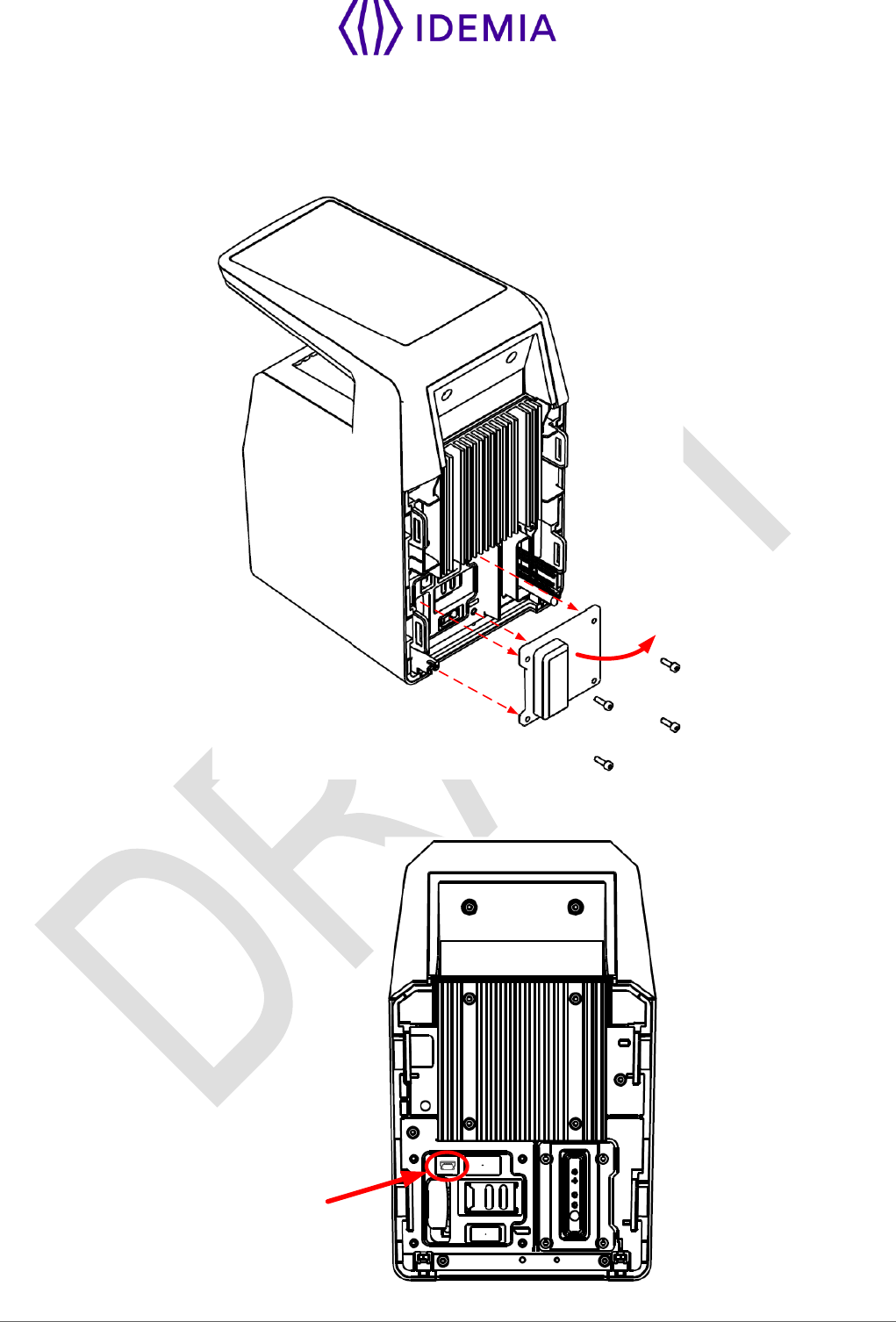
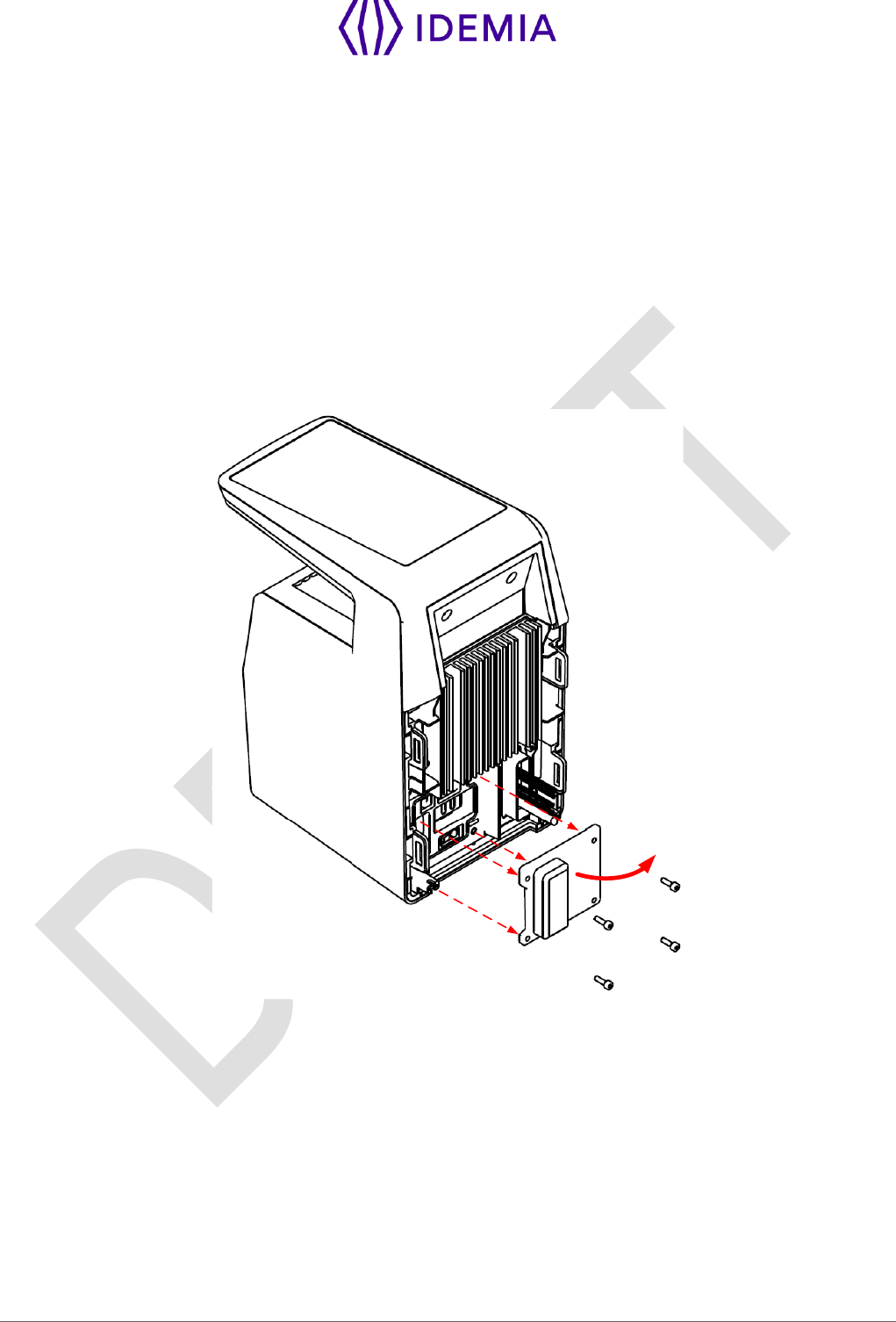
4.10 > Internal USB connection
Remove the 4 screws of the cover, as shown on the following drawing. Then remove the cover.
Then you can see a Mini USB plug.
Mini USB
type B
connector
Figure 23: Internal USB connection

55
MorphoWave Compact - 2018_2000035853
The internal Mini USB-type B can be used for administration only to connect a mass storage USB key
(with a standard Mini USB-type B / USB-type A female OTG adapter).
This cable can be found in Idemia catalogue with ref TBD.
Please refer to MorphoWave Compact Administration Guide for more information.
USB connection is limited to USB key connection (power consumption shall not exceed
200mA)
56
MorphoWave Compact - 2018_2000035853
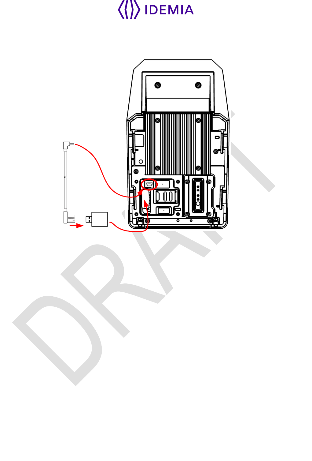
4.11 > Wi-Fi™ dongle installation
Wi-Fi™ dongle shall be installed inside the product and connected to the internal USB Mini B (at the rear
of the terminal) using Idemia cable provided in the kit.
Product integrating Wi-Fi™ dongle shall not be exposed to temperature exceeding 35°C and shall not be
exposed to direct sun.
Wi-Fi™ feature requires the product to be powered from an external DC 12V to 24V power supply (the
PoE+ doesn’t provides enough power for both the terminal and the Wi-Fi™ dongle).
Only Wi-Fi™ USB dongle delivered by Idemia (kit reference 293686787, containing the dongle and the
cable) may be installed with the terminal for WLAN (Wireless Local Area Network) operation.
Remove the cover on the rear panel:
57
MorphoWave Compact - 2018_2000035853
Then plug the Wi-FiTM dongle on the provided cable, connect the cable on the Mini-USB socket, and fit the
dongle inside the hole, as described on the following picture:
2. connect
1. connect 3. Insert the
dongle in the hole 4. Attach the cover and
tighten the screws
Figure 24: Wi-Fi™ dongle installation
Close the product with the cover and tighten the 4 screws.

58
MorphoWave Compact - 2018_2000035853
5 / User interface

59
MorphoWave Compact - 2018_2000035853
5.1 > Modes for controlling access rights
5.1.1 > Introduction
The MorphoWave Compact terminal offers several methods for controlling access rights: it needs to be
configured in one of the following four modes:
Identification mode,
Authentication mode (requires a contactless smartcard reader in the terminal),
Multi-factor mode (requires a contactless smartcard reader in the terminal),
Proxy mode
Refer to MorphoWave Compact Administration Guide for more information on Access Control.
5.1.2 > Identification mode
The Identification process of the MorphoWave Compact terminal proceeds by comparison of the biometric
data of the finger placed on the biometric sensor, with all the biometric data stored in the database.
It means that the biometric data of the allowed users must be stored in the internal database before they
can request the access on the terminal. This biometric data is acquired either directly on the terminal (using
the embedded), or on an enrolment system using the same type of biometric sensor.
The access control by identification process is started when a finger is detected on the biometric sensor
When the user requests the access, his identity is unknown, and it is the terminal that searches for his
identity. The terminal grants the access if a match is found (the user is identified); otherwise the access is
denied (the user remains unknown).
For further information, please see the "Identification mode" section in the MorphoWave Compact
Administration Guide.
5.1.3 > Authentication (verification) mode
Unlike the "identification" mode, the user identity must be known in order to execute the authentication
process.
Indeed, authentication is an identity verification process: the user provides his identity and the terminal
checks it with the relevant process.
This mode doesn’t compare the user’s data to the data of several users: it compares the data provided by
the user with the reference data provided by the same user during enrollment phase. The data can be on
a card presented to the terminal or in a database and ID is provided by the user.
Access is authorized if the terminal finds a correspondence.
For further information, please see the "Authentication mode" section in the MorphoWave Compact
Administration Guide.
5.1.4 > Multi-factor mode
In this mode, the "identification" and "authentication" modes are available simultaneously; the user decides
which control method will be used:
by placing his finger on the sensor, thereby triggering the identification process,
by placing his contactless card on the reader, thereby triggering the authentication process,

60
MorphoWave Compact - 2018_2000035853
This is the default mode for terminals fitted with a contactless smartcard reader.
For further information, please see the "Multi-factors method" section in the MorphoWave Compact
Administration Guide.
5.1.5 > Proxy mode
The Proxy mode is an operating mode where the access control main application is located in a distant
system. This is not a standalone mode like Identification and Authentication modes.
It means that the terminal becomes a slave of the host system application. The access control application
is running on the host system and uses MorphoWave Compact terminal high level functions:
Identification function
Authentication function
Read data on a contactless card
Access control result signal command
The MorphoWave Compact terminal is driven through an Ethernet (or Wi-Fi™) link using TCP, SSL or TLS
protocol.
The MorphoWave Compact terminal acts as a server: it is either waiting for a command or executing a
command.
The commands allowed by the MorphoWave Compact terminal are described in the MorphoWave
Compact Host System Interface Specification document.
For further details about SSL or TLS on the MorphoWave Compact terminal, please refer to the
MorphoWave Compact Administration Guide.
5.1.6 > External database mode (also called polling mode)
When external database mode is activated, the MorphoWave Compact terminal does not verify user
template in its local database. This mode is useful when the user templates are stored in external
database.
When authentication is initiated on the terminal, the terminal will poll the user ID to external controller. On
polling out the ID, the corresponding template (if exists) is fetched from the external database and is
authenticated against user’s biometric on the terminal. Once the template request is posted to the external
database, the terminal shall wait for the finger template from the external database to start authentication.
Further process shall be same as authentication.
Polling Process using buffer:
The user’s input ID will be queued in the terminal’s queue, which is polled by external application.
External application waits for the User ID by polling the buffer. After getting an ID, it will search the
template in database and send template to terminal for further authentication.
The user is authenticated by the external device and granted access accordingly.
MorphoWave Compact terminal also has distant commands to retrieve polling buffer status and polling
buffer data. Refer to the MorphoWave Compact Host System Interface Specification document.
How to Activate?
External database mode can be activated through Webserver > Complete Configuration, by setting
“ucc.enable_external_database” parameter to 1. Only an admin user can activate polling mode. You can

61
MorphoWave Compact - 2018_2000035853
refer to the MorphoWave Compact Host System Interface Specification document to know how to set this
parameter.
Configuring the terminal
MorphoWave Compact terminals are standalone biometric systems which offers advance features for
access control. MorphoWave Compact terminals are equipped with a facility to support the
MorphoAccess® and Bioscrypt legacy systems.
When MorphoWave Compact terminal is set in any of the legacy modes, it supports the database
structures and configurations of the selected legacy system. When the terminal is booted for the first time,
user can select any of the following modes:

62
MorphoWave Compact - 2018_2000035853
5.1.7 > MorphoWave Compact native mode
MorphoWave Compact terminal is by default in native mode, that is named MA5G. It will support the new
features and configurations only in the native mode.
NOTA : When terminal mode is switched from MA5G to Morpho legacy mode, the entire
configuration (excepted communication links) and all databases are erased
NOTA : The terminal is rebooted on mode change and factory settings are applicable.
Once the product is configured in native mode, the following methods can be used to configure the
terminal:
through the Ethernet interface (remote management)
through a Wi-Fi™ connection (license and dongle required)
Configuration procedures are described inside the MorphoWave Compact Administration Guide as follows:
Section 4: Terminal Configuration And Administration

63
MorphoWave Compact - 2018_2000035853
5.1.8 > Anti-tamper / anti-pulling switches
Please refer also to “Tamper Switch” section.
These switches are activated as soon as there is enough pressure applied on the terminal against the
wall. They are deactivated as soon as this pressure is not big enough, e.g. when the terminal is pulled out
of the wall.
When the switches are deactivated, the MorphoWave Compact terminal acts as required by the related
configuration key (see MorphoWave Compact Administrator / User Guide for key configuration
description):
Ignore the event (default): useful during normal maintenance operations.
Send an alarm message to the Central Access Controller, through the usual channel of the access
control result messages (Wiegand, DataClock, RS485, Ethernet or Wi-Fi™). An alarm switch (relay
contact) is directly available on block terminal «tamper switch pins». Please refer to “Wiring overview”
and to “Tamper Switch” sections.
Generate an audible alarm signal with the speaker and an alert message on the screen.

64
MorphoWave Compact - 2018_2000035853
6 / Accessories, Software Licenses and
PC Applications

65
MorphoWave Compact - 2018_2000035853
6.1 > Compatible Accessories, Licenses and Software
The following items can be ordered directly to Idemia or to an official distributor, so as to enjoy all the
features of your MorphoWave Compact terminal:
Power supply units,
Contactless smartcards: MIFARE® 1k, 4k; DESFire® 2k, 4k, 8k,
MA WI-FI PACK: containing a Wi-Fi™ USB dongle and a Wi-Fi™ license to activate Wi-Fi™ capability
on your terminal,
User database size licenses (MA_10K_USERS, MA_50K_USERS, MA_100K_USERS): enabling
database size upgrade from 3,000 to 10,000, 20,000, 50,000 or 100,000 users capacity (max 3 fingers
per record) at creation of the database. Requires Micro SD card in the terminal.

66
MorphoWave Compact - 2018_2000035853
6.2 > Compatible PC applications
MorphoWave Compact terminals are fully compatible with:
MorphoManager (version 11 or higher)
Morpho Integrator’s Kit (MIK) software development kit (version 6 or higher).
MorphoBioToolBox (version 3.4.3 or higher)
Using Legacy Morpho mode, MorphoWave Compact is also compatible with:
MEMS (version 7.3.1 or higher),
MIK (version 5.4 or higher),
The limitations in Morpho Legacy mode are described in the following document:
MorphoWave Compact Release Note - Legacy Morpho limitations

67
MorphoWave Compact - 2018_2000035853
7 / Recommendations

68
MorphoWave Compact - 2018_2000035853
Global warning
The manufacturer cannot be held responsible in case of non-compliance with the following
recommendations or incorrect use of the terminal.
General precautions
Do not attempt to repair your terminal yourself. The manufacturer cannot be held responsible for any
damage/accident that may result from attempts to repair components. Any work carried out by non-
authorized personnel will invalidate your warranty.
Do not expose your terminal to extreme temperatures.
Use your terminal with original accessories. Attempts to integrate unapproved accessories to the
terminal will void your warranty.
Due to electrostatic discharge, and depending on the environment, synthetic carpet should be avoided
in areas where the terminal has been installed.
Do not tilt the product.
Do not use blunt force on the product.
Do not attach anything to the product.
Do not place anything on the product.
Switch off the device before unplugging it.
Biometric performance
Do not scratch the product, particularly on the glass, because the performance of the product depends
of the state of the glass surface and its anti-reflective face.
Clean the glass every day to optimize performance of the product.
Avoid direct sun light on the product.
Areas containing combustibles
It is strongly recommended that you do not install your terminal in the vicinity of gas stations, petroleum
processing facilities or any other facility containing flammable or combustible gasses or materials.
Specific precautions for terminals equipped with a contactless smartcard reader
It is recommended to install terminals equipped with a contactless smartcard reader at a certain
distance (> 30cm) from metallic elements such as iron fixations or lift gates or radio product (such as
contactless smartcard reader). Performances in terms of contactless badge reading distance will
decrease when metallic elements are closer.
Ethernet connection
It is recommended to use a category 5 shielding cable (120 Ohms). It is also strongly recommended
to insert a repeater unit every 90m.
Extreme care must be taken while connecting Ethernet wire to the terminal block board since low
quality connection may strongly impact Ethernet signal sensibility.
It is recommended to connect Rx+ and Rx- with the same twisted-pair wire (and to do the same with
Tx+/Tx- and the other twisted-pair wire).
Date / Time synchronization
The terminal clock has a +/-10 ppm typical time deviation at +25°C (roughly around +/- 6 sec per 48
hours). At lower and higher temperature (but within normal operating temperatures), deviation may be
more important (worst case: - 14 seconds per 48 hours).

69
MorphoWave Compact - 2018_2000035853
If the terminal is used in an application requiring high time precision, we recommend synchronizing
regularly your terminal time with an external clock (using NTP). Every 24 hours is usually enough for
most applications.
Please note that the date/time of the terminal is protected from power failure during at least 24 hours.
If the duration of the power failure or power down is longer, the date/time of the terminal will be lost.
Cleaning precautions
Use a dry cloth to clean the terminal, especially the front face. It is recommended that the product be
cleaned daily to ensure the best performance level over its lifetime.
The use of acid liquids, alcohol or abrasive materials is prohibited.
Use dry air spray to remove the dust out of the sensor glass.

70
MorphoWave Compact - 2018_2000035853
8 / Annex 1 : finger placement
recommendations
71
MorphoWave Compact - 2018_2000035853
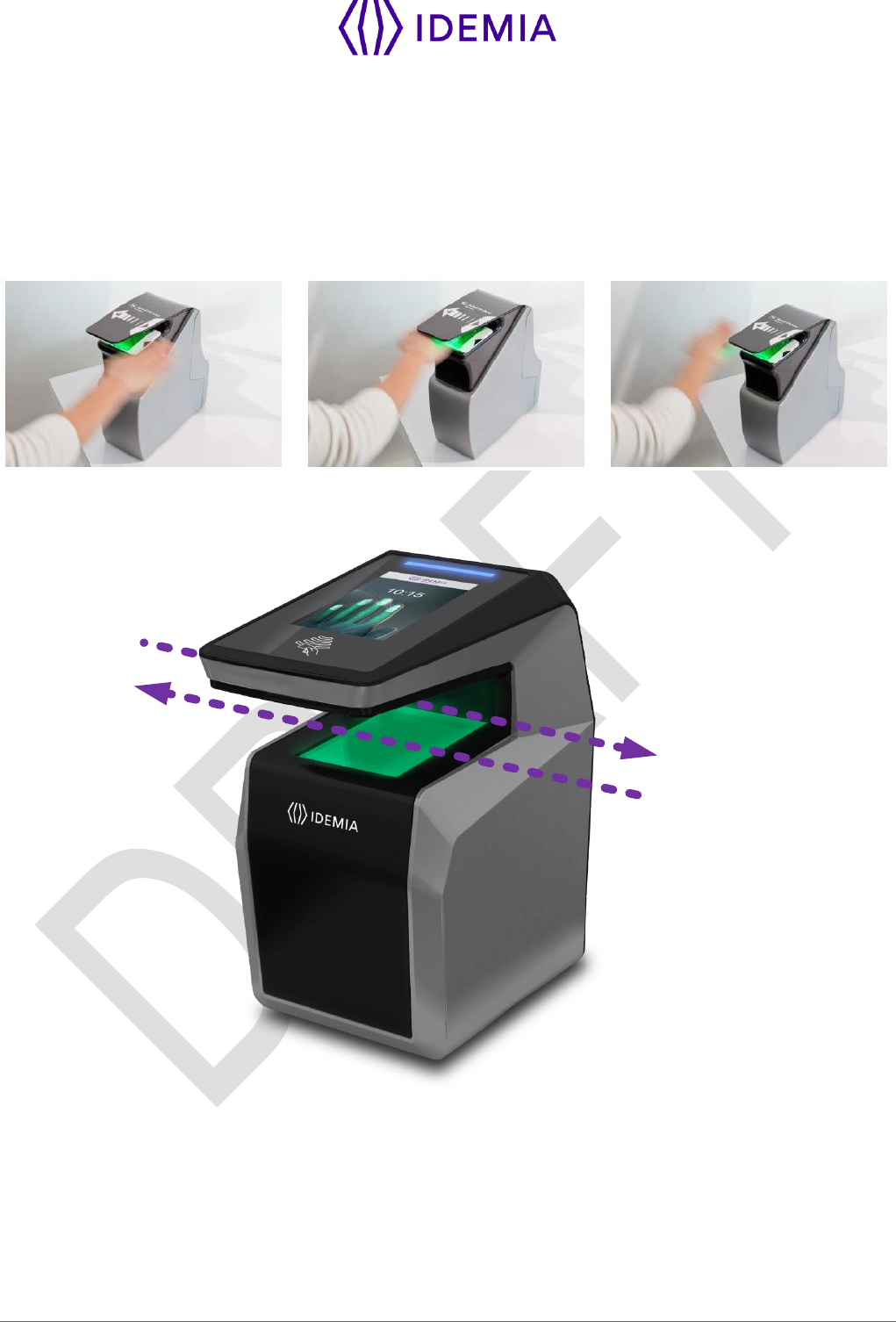
8.1 > Main principles
MorphoWave Compact is a biometric acquisition terminal which captures fingerprints by the applicant
waving their hand through the active volume. The product can track and capture simultaneously up to 4
fingerprints at a maximum speed of 0.5m/s.
To acquire fingerprints, the applicant waves his hand between the product glass and protective cap as
shown in the Figure below.
Note: The recommended hand wave direction is from right to left, even though the sensor will accept both
directions.
Hand wave from the right
Hand wave from the left
72
MorphoWave Compact - 2018_2000035853
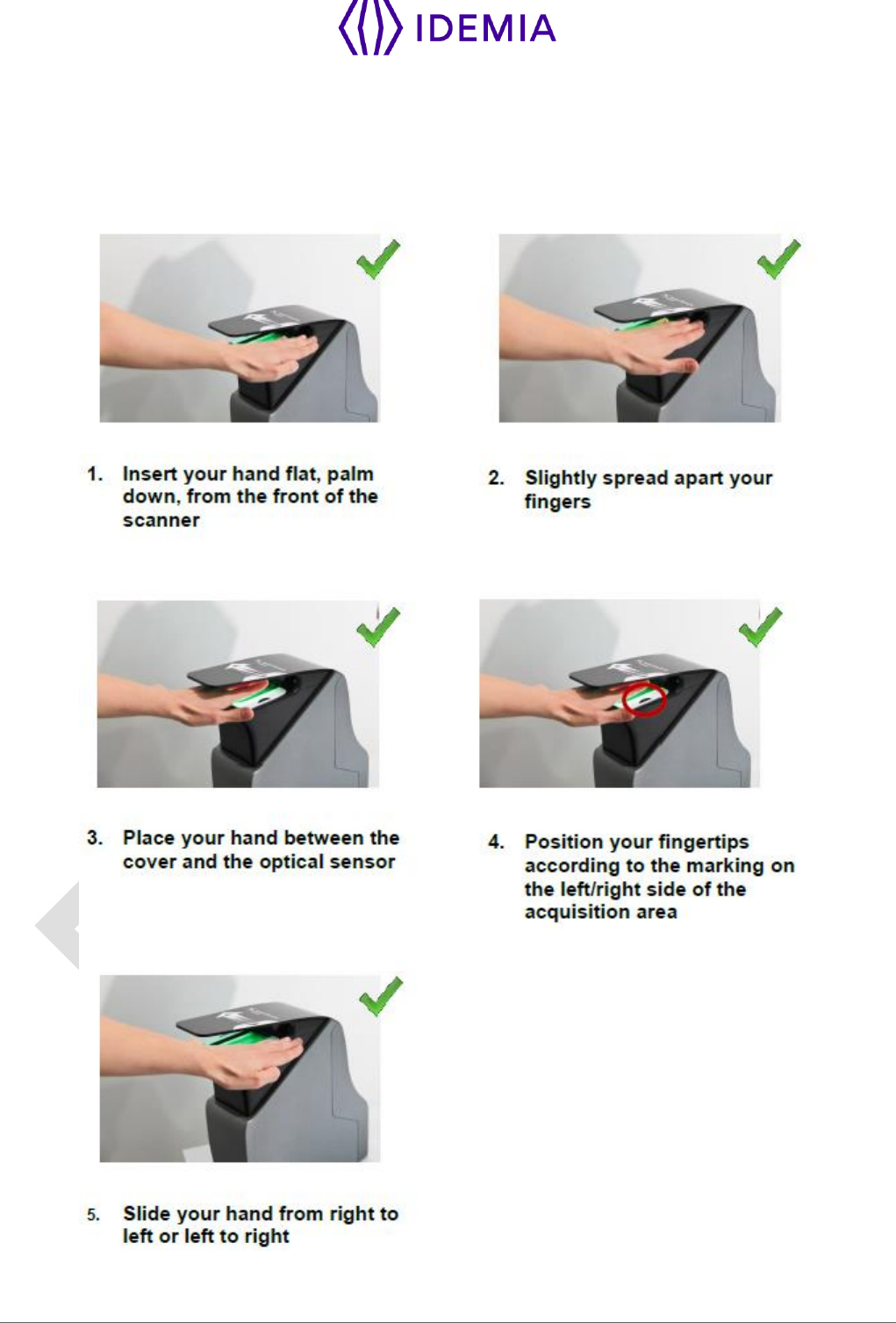
8.2 > Capture recommendations
Proper Use
Below are several illustrations and guidelines on how to best use your new MorphoWave Compact
device.
73
MorphoWave Compact - 2018_2000035853
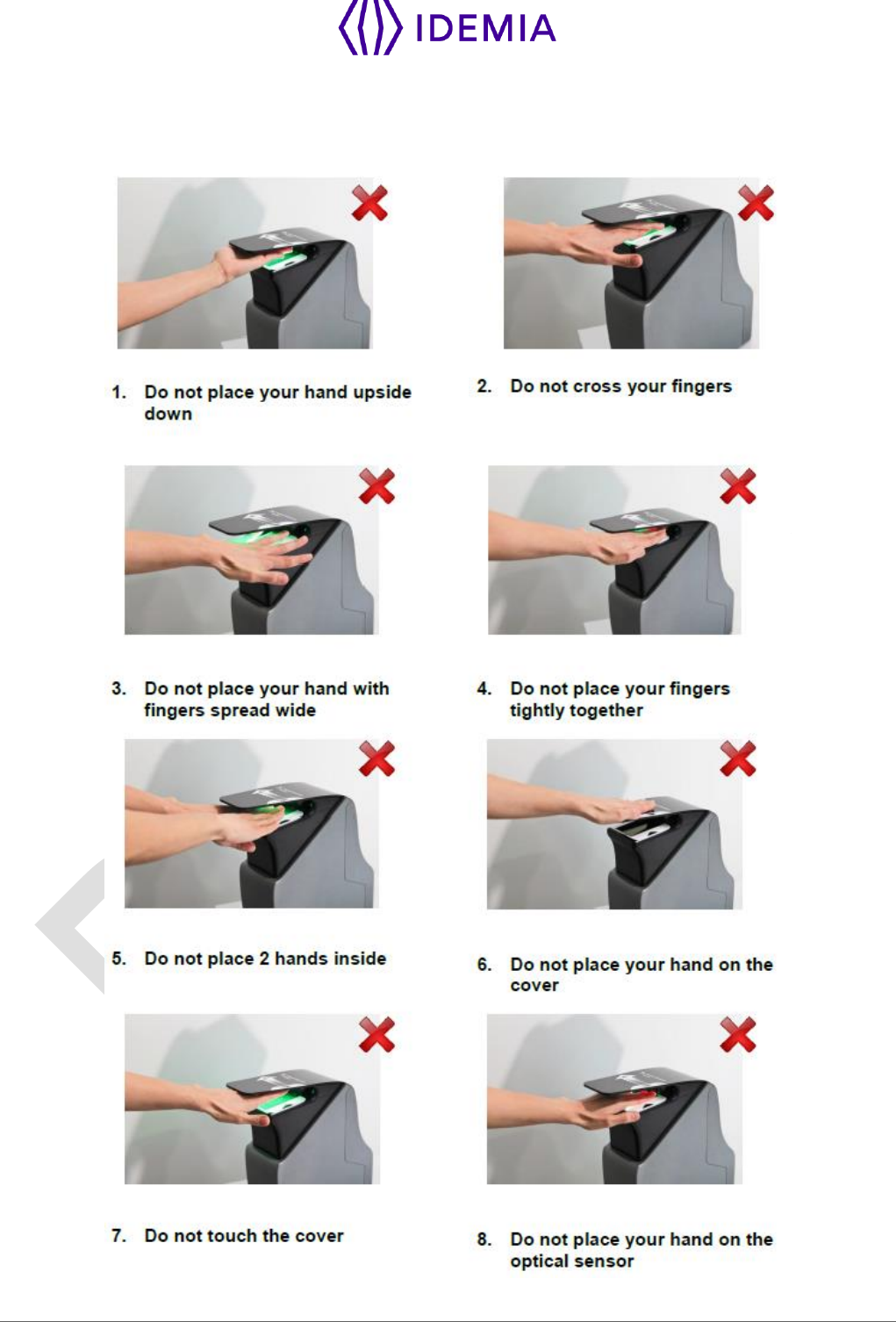
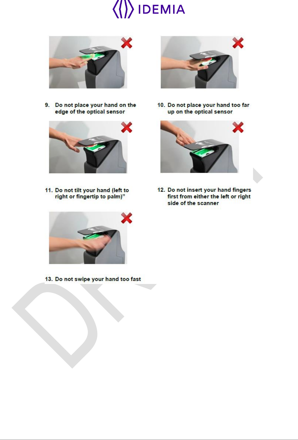
Improper Use
The following illustrations show what NOT to do when using Finger on the Fly.
74
MorphoWave Compact - 2018_2000035853

75
MorphoWave Compact - 2018_2000035853
9 / Annex 2 : Bibliography

76
MorphoWave Compact - 2018_2000035853
9.1 > How to get the latest versions of documents
The last version of the documents can be downloaded from our web site at the address below:
www.biometric-terminals.com
(Login and password required).
To request a login, please send us an email to the address below:
hotline.biometrics@morpho.com

77
MorphoWave Compact - 2018_2000035853
9.2 > Documents about the MorphoWave Compact terminal
Documents about installing the terminal
MorphoWave Compact Installation Guide,
Ref. 2018_2000035853
This document describes terminal physical mounting procedure, electrical interfaces and connection
procedures. This document is in English.
Documents about administrating / using the terminal
MorphoWave Compact Quick User Guide,
Ref. 2018_2000035854
This document gives a quick overview of the product and the basics of configuration and use. This
document is in English.
MorphoWave Compact Administrator Guide,
Ref. TBD
This document describes the different functions available on the terminal and procedures for configuring
the terminal. It also contains the full description of all the configuration parameters for the terminal. This
document is in English.
MorphoWave Compact Parameters Guide,
Ref. TBD
This document contains the full description of all the terminal configuration parameters. This document is
in English.
Documents for the developer
MorphoWave Compact Host System Interface Specification,
Ref. TBD
This document describes the commands supported by the MorphoAccess® terminal. This document is in
English.
MorphoWave Compact Remote Message Specification,
Ref. TBD
This document describes the format of messages sent by the terminal to a distant system. This document
is in English.
Release note
For each firmware version, a release note is published describing the new features, the supported
products, the potential known issues, the upgrade / downgrade limitations, the recommendations, the
potential restrictions…

78
MorphoWave Compact - 2018_2000035853
10 / Annex 3 : Support

79
MorphoWave Compact - 2018_2000035853
10.1 > Troubleshooting
The terminal IP address is unknown or it is not possible to connect to the terminal
Use terminal interface to configure a valid set of network parameters in your terminal.
The sensor is switched off
Check that the database contains at least one record.
Check that the identification mode is enabled.
The terminal returns erratic responses to Ping commands
Check the subnet mask.
Ask the network administrator for the correct value.
Check that each device connected to the network has a different IP address.
10.2 > Technical Support and Hotline
North America:
Mail: cscenter@morpho.com
Tel: +1 888 940 7477
South America:
Mail: cscenter@morpho.com
Tel: +1 714 575 2973
South Africa:
Mail: sec.san.bio.support@morpho.com
Tel: + 27 11 286 5855
India:
Mail: support.morphoindia@morpho.com
Tel: 0120-4699900
Europe and rest of the world:
Mail: hotline-biometrics@morpho.com
Tel: +33 1 30 20 30 40
(9H00am to 5H30pm French Time, Monday to Friday)
Web site
For the latest firmware, software, document releases, and news, please check our websites :
North and South America: e-mailing cscenter@morpho.com with your name, phone number, product
serial number and “Send Links For MorphoWave Compact Documents” in the subject line
Other countries: please visit our web site www.biometric-terminals.com (To get your log in and
password please contact your sales representative).

Copyright 2017 - Photo: GettyImages-656164914
Copyright 2017 - Photo: GettyImages-656164914