IDENTIFICATION DEVICE TECHNOLOGY ISC-101A THE PRODUCT IS CARDREADER USING RF CARD User Manual
IDENTIFICATION DEVICE TECHNOLOGY, INC. THE PRODUCT IS CARDREADER USING RF CARD
User Manual

User Manual
ISC-101A

COPYRIGHT
Manual COPYRIGHT (C) 2004 IDT Inc. All rights reserved.
The Information in this document is subject to change without notice. IDT Inc.
reserves the right to revise this document and to make changes from time to time in
the content hereof without obligation to notify any person or persons of such
revisions or changes. The software described in this document is supplied under a
license agreement and is protected by international copyright laws. You may copy it
only for the purpose of backup and use it only as described in the License
agreement. Any implied warranties including any warranties of merchantability or
fitness for a particular purpose are limited to the terms of the express warranties set
out in the license agreement.
Program COPYRIGHT (C) 2003-2004 IDT Inc. All rights reserved.
Trademarks
BioScan is a registered trademark of IDT Inc.
BSC-101/201/301/401 is a registered trademark of IDT Inc.
Other products, trademarks or registered trademarks are the property of their
respective owners.

WARNING!
• 15.19:
THIS
DEVICE COMPLIES WITH PART 15 OF THE FCC RULES OPERATION
THIS
DEVICE
COMPLIES
WITH
PART
15
OF
THE
FCC
RULES
.
OPERATION
IS SUBJECT TO THE FOLLOWING TWO CONDITIONS: (1) THIS DEVICE MAY NOT
CAUSE HARMFUL INTERFERENCE, AND (2) THIS DEVICE MUST
ACCEPT ANY INTERFERENCE RECEIVED, INCLUDING INTERFERENCE THAT MAY
CAUSE UNDESIRED OPERATION
CAUSE
UNDESIRED
OPERATION
.
• 15.21:
The user manual for an intentional or unintentional radiator shall caution the user that
changes or modifications not expressly approved by the party responsible for compliance
could void the user’s authority to operate the equipment.
• NOTE: THE GRANTEE IS NOT RESPONSIBLE FOR ANY CHANGES OR
MODIFICATIONS NOT
• EXPRESSLY APPROVED BY THE PARTY RESPONSIBLE FOR COMPLIANCE. SUCH
MODIFICATIONS
COULD VOID THE USER
’
S AUTHORITY TO OPERATE THE
MODIFICATIONS
COULD
VOID
THE
USER S
AUTHORITY
TO
OPERATE
THE
EQUIPMENT.

WARRANTY
Limited Warranty:
All Products sold to Dealer hereunder shall be subject to IDTi standard warranty for
the Product included with the Product by IDTi (“Product Warranty”). The Product Warranty shall be
extended to end user purchasers of the Products from Dealer who purchases such Products within twelve
(12) months of the date the Products are shipped to Dealer. Provided within the aforementioned time
period, the warranty period for a Product shall commence upon the date stated in the Product Warranty.
Dealer shall not extend any warranty regarding the Products other than IDTi then standard warranty. The
limited warranty statement included in the Product Warranty is the exclusive statement of the controlling
terms and conditions of the limited warranties on the Products. Nothing in this Agreement or any other
written document or any oral communications with Dealer or other parties may alter the terms and
conditions of the Product Warranty. IDTi may, in its sole discretion, revise its limited warranties from time
to time, however; no change in limited warranties will affect Product orders already accepted by IDTi.
Dealer agrees to only pass on to Dealer’s end-users IDTi limited warranties and Dealer will be liable for
any greater warranty that Dealer purposely or inadvertently transfers to end-users. Dealer will indemnify,
defend and hold IDTi harmless for any damages or other costs that arise because of Dealer’s failure to
properly inform Dealer’s end-users of current limited warranties.
Warranty Disclaimer: IDTi MAKES NO EXPRESS OR IMPLIED WARRANTIES FOR THE PRODUCTS
EXCEPT THOSE INCLUDED IN THE PRODUCT WARRANTY. IDTi DISCLAIMS ALL OTHER
WARRANTIES, EXPRESS OR IMPLIED, INCLUDING, WITHOUT LIMITATION, IMPLIED
WARRANTIES OF MERCHANTABILITY AND FITNESS FOR A PARTICULAR PURPOSE.

차례
•ISC-101A ………………….……………………..5
•CHAPTER 1 ……………………………………..9
–ENROLL
–EDIT
–DELETE
–VIEW
•CHAPTER 2 ……………………………………27
–SYSTEM SETUP
–SENSOR SETUP
–ALARM SETUP
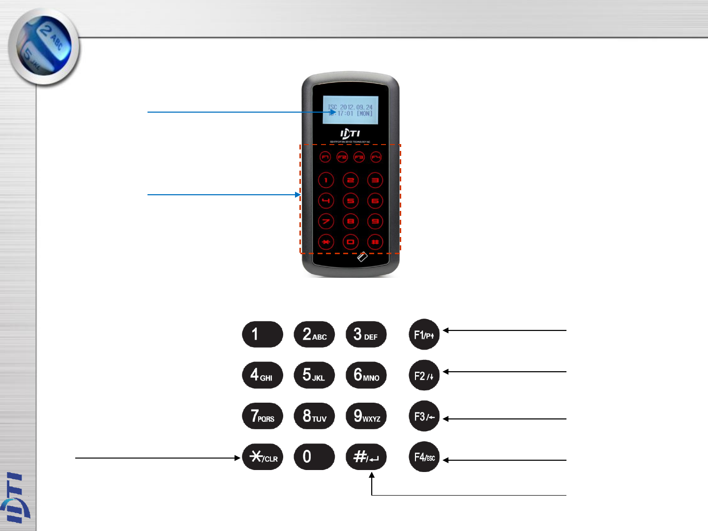
ISC-101A
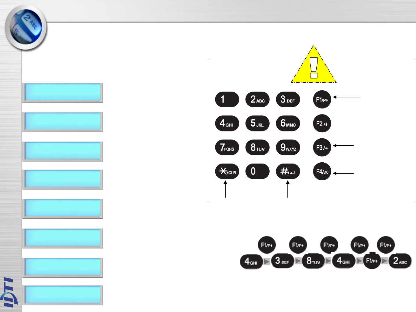
Clear
Enter
Escape
Backspace / Detail View
Scroll Down
Program / Scroll Up / Space
LCD Display
Proximity Reader
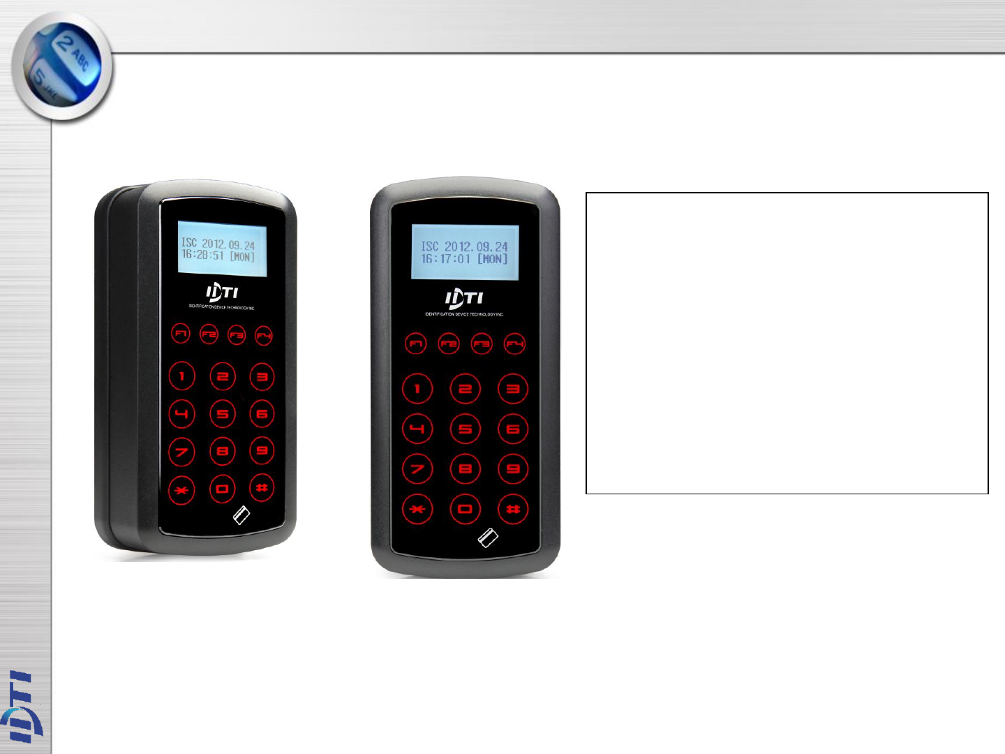
ISC-101A Descriptions
► User Registration : 100,000 Users
► Transaction Buffer : 614,000 Transactions
► CPU : 32bit MCU
► POWER : 12V DC 1A
► SIZE : H128 X W63 X D34mm
► Temperature : 0℃~50℃
► Humidity : 10%~90%
► Speed : 0.5~1Sec(1:1 authentication).
► Card Reading Length : ~10 cm
► Communication : RS-232 , TCP/IP, WIEGAND
► Input / Output : 2 In / 1 Out
► Material: ABS (Polycarbonate)
ISC-101A

ENROLL USER - MAIN MENU 1
ENTERING THE SYSTEM MENU ..……….……....…….…… 9
1.CARD ………………………………………………….……..…..10
2.CARD BLOCK ……………………………………….………...11
3.CARD BLOCK2 ……………………………………..………….12
EDIT USER - MAIN MENU 2
1.USER ID…………………………………………………..….…....14
2.CARD & 3.LEVEL ………………………………………………..15
4.USER NAME ……………………………..………………………16
5.USER ANTI PASS …………………………………….………….17
6.OPTION-ID ONLY PASS ………………………………………18
7.USER TWO MAN …………………………………….………….19
VIEW - MAIN MENU 3
1.USER LIST…….………………………………………….……..21
2.EVENT…………………………………………………………..22
3.FIRMWARE & FINGER………………………………………..23
DELETE USER - MAIN MENU 4
1.SINGLE USER & 2. ALL USER…………………………………25
CHAPTER 1
If Administrator has been enrolled :
If Administrator has been enrolled:
ENTERING THE SYSTEM MENU
ENTER ADMIN ID
12345678
BSC 2004.06.25
12:12:12 [FRI]
MAIN PROGRAM
F1:UP F2:DN
BSC 2004.06.25
12:12:12 [FRI]
MAIN PROGRAM
F1:UP F2:DN
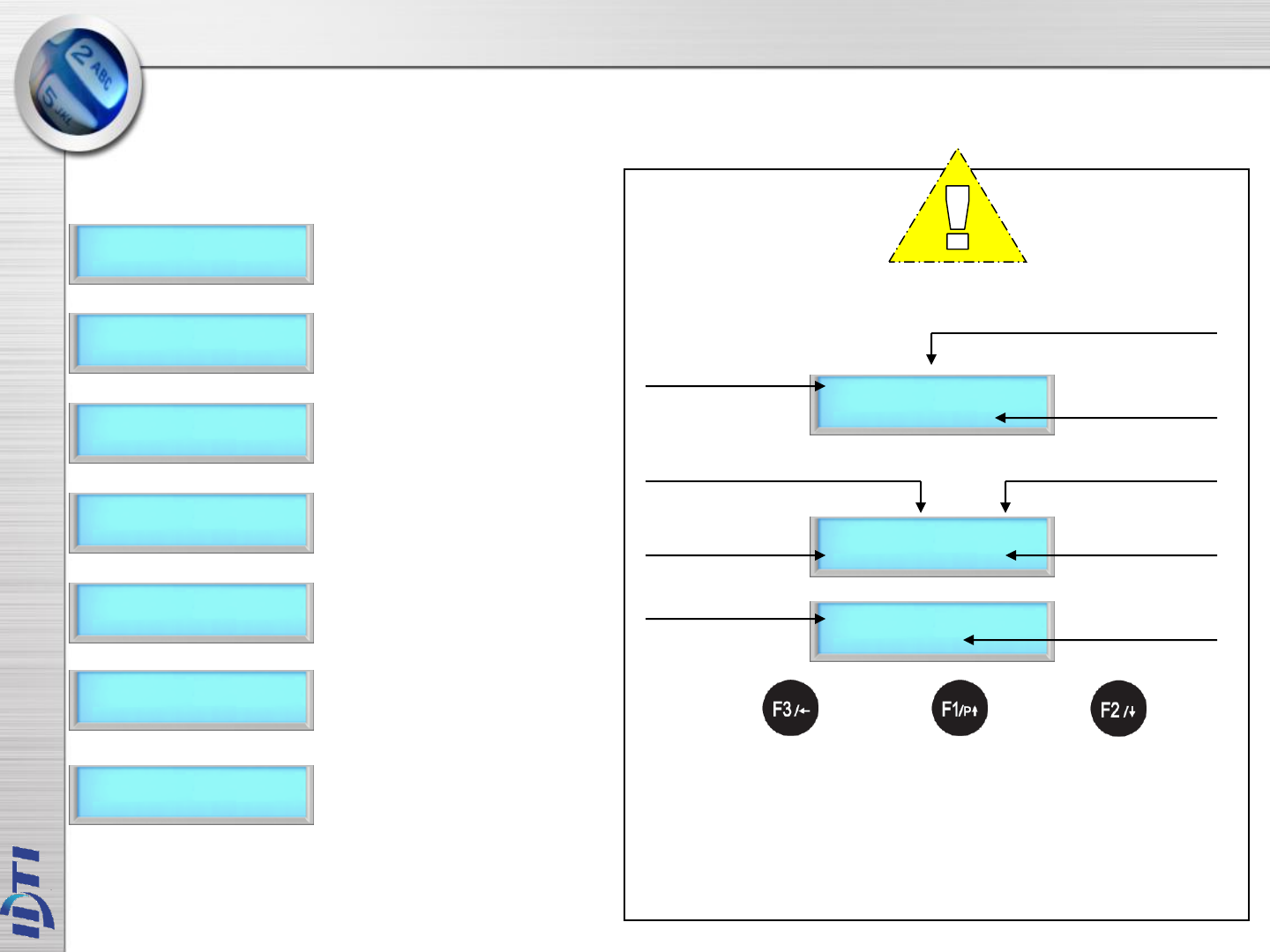
When the reader is powered on with no user enrolled in the unit, anyone can enter the system menu by
pressing the F1 key. If you are enrolling the first administrator card via the reader's keypad, you must first
determine the 1~16 digit PIN that the administrator will use. Once this PIN is determined, the administrator
must be present to enroll their card into the reader. Note that this operation is not valid if there are
administrator card in the reader.
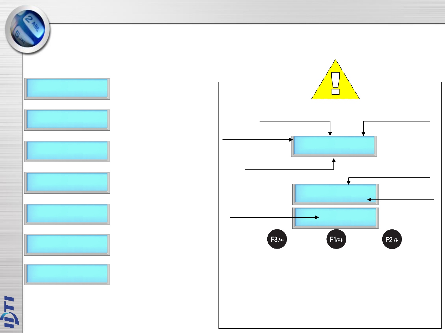
1. Press F1/P key to enter system mode.
2. Key in administrator ID followed by
the # key
3. Present either card which ever
administrator has been enrolled with.
For now we will use the fingerprint.
PRESENT
CARD
4. Now you're into system mode.
Press F1 key to scroll up the main menu
Press F2 key to scroll down the main menu
1. Press F1/P key to enter system mode
2. Now you're into system mode.
Press F1 key to scroll up the main menu
Press F2 key to scroll down the main menu NOTE :
BSC-101A factory default has no system administrator password. If
you've just purchased the unit, you should be able to get into the system
mode by pressing the F1 key. Go to ENROLL USER to enroll template or
card.
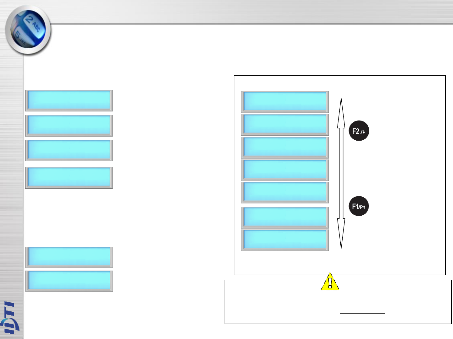
1> ENROLL USER
#:ENTER F4:ESC
Lists of Main Menu
2> EDIT USER
#:ENTER F4:ESC
3> VIEW
#:ENTER F4:ESC
4> DELETE
#:ENTER F4:ESC
5> SYSTEM SETUP
#:ENTER F4:ESC
6> SENSOR SETUP
#:ENTER F4:ESC
7> ALARM SETUP
#:ENTER F4:ESC
1. Press F1/P key to enter system mode.
2. Press F1 key to scroll up, F2 key to
scroll down the main menu

ENROLL CARD
ENROLL CARD BLOCK – not delete currently enrolled user
ENROLL CARD BLOCK 2 – delete enrolled user
1. ENROLL USER

ENROLL USER – 1.CARD
1 – 16 DIDTIS
ENTER USER ID
ENTER USER ID
12345678
PRESENT CARD
ENROLL COMPLETED
CONT:# STOP:ANY
ENROLL USER
2.CARD
This command is used to add typical card only users to the reader so that they will be able to gain entry
to the location guarded by the reader. Total number of users are 100,000 based on card users only. The
enrollment procedure is identical to adding fingerprint.
MAIN PROGRAM
F1:UP F2:DN
1> ENROLL USER
#:ENTER F4:ESC
1> ENROLL USER
F1:UP F2:DN
1. Press F1/P key to enter system mode.
2. Press the # key to select ENROLL
USER menu
4. Press the # key to add a user card
6. Key in user ID from 1 to 16 digits as
shown in next figure.
7. Key in user ID followed by the # key
3. Press F1 or F2 key to select sub-menu
8. Present user card to the reader or
key in card number manually followed
by the # key
9. Enroll completed. Press # key to
continue adding card or press any
other key to exit off the sub-menu
LEVEL
1:USER 2:ADMIN
5. Select user level by pressing 1 or 2
ENROLL USER – 2.CARD BLOCK1
START USER ID
ENTER USER ID
1000
START USER CARD
USER CARD
1000
REG. USER NUM
This command is used to Enrolling a range of cards, Block enrollment by card number range is best used
when there is a large quantity of sequential ID numbered cards or credentials. Cards or credentials do not
have to be on hand when enrolled through the block enrollment by card number range process, but you
must have the facility code.
ENROLL USER 0001
>>>
1> ENROLL USER
4.CARD BLOCK
6. Key in first user ID followed by the # key
7. Enter in the first card number as shown
below
8. Key in first card number followed by
the # key
9. Enter in the total number of cards to
be enrolled as shown below.
USER COUNT
100
10. Key in total number of cards to be
enrolled and press the # key.
11. Enrolling user card block. Please
wait unit the process finishes. This
might take up to 5 minutes depending
on the total number of card block size.
ENROLL COMPLETED
CONT:# STOP:ANY
MAIN PROGRAM
F1:UP F2:DN
1> ENROLL USER
#:ENTER F4:ESC
1> ENROLL USER
F1:UP F2:DN
1. Press F1/P key to enter system mode.
2. Press the # key to select ENROLL
USER menu.
4. Press the # key to add block of card
user
5. Enter in first number of the block ID.
This will be the first ID number of the
card as shown in the next figure
3. Press F1 or F2 key to select sub-menu
12. Enroll completed. Press the # key
to continue adding another or press
any others to exit off the sub-menu.
NOTE :
This option will write block of cards in empty slot of the
memory and will not delete currently enrolled user. Card
Block 1 will take more time than card block2 since it will
search for empty slots in memory to enroll. Consider using
card block2 if the memory is empty or stored memory is no
longer needed.
This command is used to Enrolling a range of cards, Block enrollment by card number range is best used
when there is a large quantity of sequential ID numbered cards or credentials. Cards or credentials do not
have to be on hand when enrolled through the block enrollment by card number range process, but you
must have the facility code.
START USER ID
ENTER USER ID
1000
START USER CARD
USER CARD
1000
REG. USER NUM
ENROLL USER 0001
>>>
1> ENROLL USER
5.CARD BLOCK2
USER COUNT
100
ENROLL COMPLETED
CONT:# STOP:ANY
MAIN PROGRAM
F1:UP F2:DN
1> ENROLL USER
#:ENTER F4:ESC
1> ENROLL USER
F1:UP F2:DN
ENROLL USER – 3.CARD BLOCK2
6. Key in first user ID followed by the # key.
7. Enter in the first card number as shown
below
8. Key in first card number followed by
the # key.
1. Press F1/P key to enter system mode.
2. Press the # key to select ENROLL
USER menu.
4. Press the # key to add block of card
user(type 2)
5. Enter in first number of the block ID.
This will be the first ID number of the
card as shown in the next figure
3. Press F1 or F2 key to select sub-menu
9. Enter in the total number of cards to
be enrolled as shown below.
10. Key in total number of cards to be
enrolled and press the # key.
11. Enrolling user card block. Please
wait unit the process finishes. This
might take up to 5 minutes depending
on the total number of card block size.
12. Enroll completed. Press the # key
to continue adding another or press
any others to exit off the sub-menu.
NOTE :
This option will write block of cards in empty slot of the
memory and will not delete currently enrolled user. Card
Block 1 will take more time than card block2 since it will
search for empty slots in memory to enroll. Consider using
card block2 if the memory is empty or stored memory is no
longer needed.

USER ID
USER FINGPERINT
USER CARD
USER LEVEL
NAME
USER ANTI-PASS
OPTION
USER TWO MAN
2. EDIT USER

EDIT USER - 1.USER ID
MAIN PROGRAM
F1:UP F2:DN
2> EDIT USER
1. USER ID
ENTER USER ID
12345678
ENTER NEW ID
87654321
2>EDIT USER
#:ENTER F4:ESC
2> EDIT USER
F1:UP F2:DN
EDIT COMPLETED
CONT:# STOP:ANY
This command is used to edit existing users ID by accessing the user ID. When editing, Administrators
have the ability to make changes to user ID only in this menu.
6. Key in new user ID followed by the # key
1. Press F1/P key to enter system mode.
2. Press the # key to select EDIT USER
menu.
4. Press the # key to edit User ID
5. Key in user ID to be edited followed
by the # key
3. Press F1 or F2 key to select sub-menu
7. Edit completed. Press the # key to
continue editing another or press any
others to exit off the sub-menu

EDIT USER - 2.CARD & 3.LEVEL
MAIN PROGRAM
F1:UP F2:DN
2> EDIT USER
3.CARD
ENTER USER ID
12345678
2>EDIT USER
#:ENTER F4:ESC
2> EDIT USER
F1:UP F2:DN
EDIT COMPLETED
CONT:# STOP:ANY
PRESENT NEW CARD
This command is used to edit existing users Card or Level by accessing the user ID. When editing,
Administrators have the ability to make changes to user Card or Level only in this menu.
MAIN PROGRAM
F1:UP F2:DN
2> EDIT USER
4.LEVEL
ENTER USER ID
12345678
2>EDIT USER
#:ENTER F4:ESC
2> EDIT USER
F1:UP F2:DN
EDIT COMPLETED
CONT:# STOP:ANY
사용자 레벨(Level) 사용자 카드 (Card)
6. Present new card to be enrolled or enter
in the card number manually followed by
the # key. Make sure the card has not
been already enrolled in the BSC-101A..
1. Press F1/P key to enter system mode.
2. Press the # key to select EDIT USER
menu.
4. Press the # key to edit user CARD
5. Key in user ID to be edited followed
by the # key
3. Press F1 or F2 key to select sub-menu.
7. Edit completed. Press the # key to
continue editing another or press any
others to exit off the sub-menu
6. Select the user level to apply new level
1. Press F1/P key to enter system mode.
2. Press the # key to select EDIT USER
menu.
4. Press the # key to edit user LEVEL
5. Key in user ID to be edited followed
by the # key.
3. Press F1 or F2 key to select sub-menu
7. Edit completed. Press the # key to
continue editing another or press any
others to exit off the sub-menu
LEVEL
1:USER 2:ADMIN
MAIN PROGRAM
F1:UP F2:DN
2> EDIT USER
5.NAME
ENTER USER ID
12345678
2>EDIT USER
#:ENTER F4:ESC
2> EDIT USER
F1:UP F2:DN
1:ENTER NAME
2:SELECT DISPLAY
ENTER USER NAME
IDTi
7. Key in appropriate display name and
then press the # key
ISC-101A is able to display custom user name instead of user ID when accessed. When the ISC-101A
is expecting a name then the number keys on the keypad become letter keys: the letters below the
keys apply. Press once to show the first uppercase letter above the key; press four times to show the
lowercase letter. When the desired letter appears on the display, press the up-arrow(F1) to move on
to the next letter in the name.
EDIT COMPLETED
CONT:# STOP:ANY
1:DISPLAY USERID
2:DISPLAY NAME
7. Select #2 to display ID by name. This
will allow BSC-101A to display custom
ID name instead of user ID
EDIT COMPLETED
CONT:# STOP:ANY
6. Press 1 key to enter user name.
This time select #2 to enter display
option
1. Press F1/P key to enter system mode.
2. Press the # key to select EDIT USER
menu.
4. Press the # key to edit user NAME
5. Key in user ID to be edited followed
by the # key.
3. Press F1 or F2 key to select sub-menu
8. Edit completed. Press the # key to
continue editing another or press any
others to exit off the sub-menu
8. Edit completed. Press the # key to
continue editing another or press any
others to exit off the sub-menu
ENTER USER NAME
IDTi C
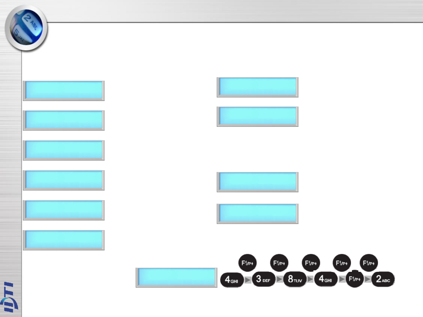
Ex) Edit “IDTi C”
3 times. 1time. 1time. 6 times 3times. 1time.
I D T i Space C
EDIT USER - 4.NAME
No of Key Press
MAIN PROGRAM
F1:UP F2:DN
2> EDIT USER
6.USER ANTI PASS
ENTER USER ID
12345678
2>EDIT USER
#:ENTER F4:ESC
2> EDIT USER
F1:UP F2:DN EDIT COMPLETED
CONT:# STOP:ANY
EDIT OPTION
1:ON 2:OFF 3:CLR
6. Press 1 key to enable anti-pass
Press 2 key to disable anti-pass
Press 3 key to forgiveness.
NOTE :
Anti-pass must be enabled in system setting. Before enabling the anti-pass in user setting, go to main menu
5.SYSTEM SETTING/submenu 12.ANTI PASS and enable the anti-pass for system.
When the system has detected an anti-pass user, that user will be denied the access to that location.
Administrator must clear that person of anti-pass by going into edit option and reset the anti-pass by selecting
3(CLR) forgiveness.
Anti pass-back is used to stop two people from using one card to gain access. This feature is designed to
protect against tailgating. Once an access is granted to an IN reader, it must be presented to an OUT
reader before another IN reader access is granted. In the event that the user did not read in at the IN
reader, and tried to read out of an area, an anti-passback violation would occur. The violation may just log
the event as an alarm condition, or may not allow the door to be released. Since users who fail to read IN
and walk in with other employees may get stranded or locked in. System Anti-Passback must be enable in
order for User Anti-passback to work properly.
1. Press F1/P key to enter system mode.
2. Press the # key to select EDIT USER
menu.
4. Press the # key to enter USER ANTIPASS
3. Press F1 or F2 key to select sub-menu
5. Enter user ID to apply anti-pass
7. Edit completed. Press the # key to
continue adding another user
fingerprint or press any others to exit
off the sub-menu
EDIT USER - 5.ANTI PASS

MAIN PROGRAM
F1:UP F2:DN
2> EDIT USER
7.OPTION (ID)
ENTER USER ID
12345678
2>EDIT USER
#:ENTER F4:ESC
2> EDIT USER
F1:UP F2:DN
EDIT COMPLETED
CONT:# STOP:ANY
EDIT OPTION
1:ON 2:OFF
ID Option is a special mode where user can access the unit with ID only. When applied, user can override
the current operating mode and access unit it with just an ID (PIN). This option can be applied to those
users who does not have card. To apply this mode to user, follow the steps bellow.
1. Press F1/P key to enter system mode.
2. Press the # key to select EDIT USER
menu.
4. Press the # key to enter OPTION (ID)
3. Press F1 or F2 key to select sub-menu
6. Press 1 key to enable ID option to this user
Press 2 key to disable ID option to this user
5. Enter user ID to apply ID option
followed by the # key
7. Edit completed. Press the # key to
continue editing another or press any
others to exit off the sub-menu
EDIT USER – 6.OPTION ID
MAIN PROGRAM
F1:UP F2:DN
2> EDIT USER
8.USER TWO MAN
ENTER USER ID
12345678
2>EDIT USER
#:ENTER F4:ESC
2> EDIT USER
F1:UP F2:DN
EDIT COMPLETED
CONT:# STOP:ANY
EDIT OPTION
1:ON 2:OFF
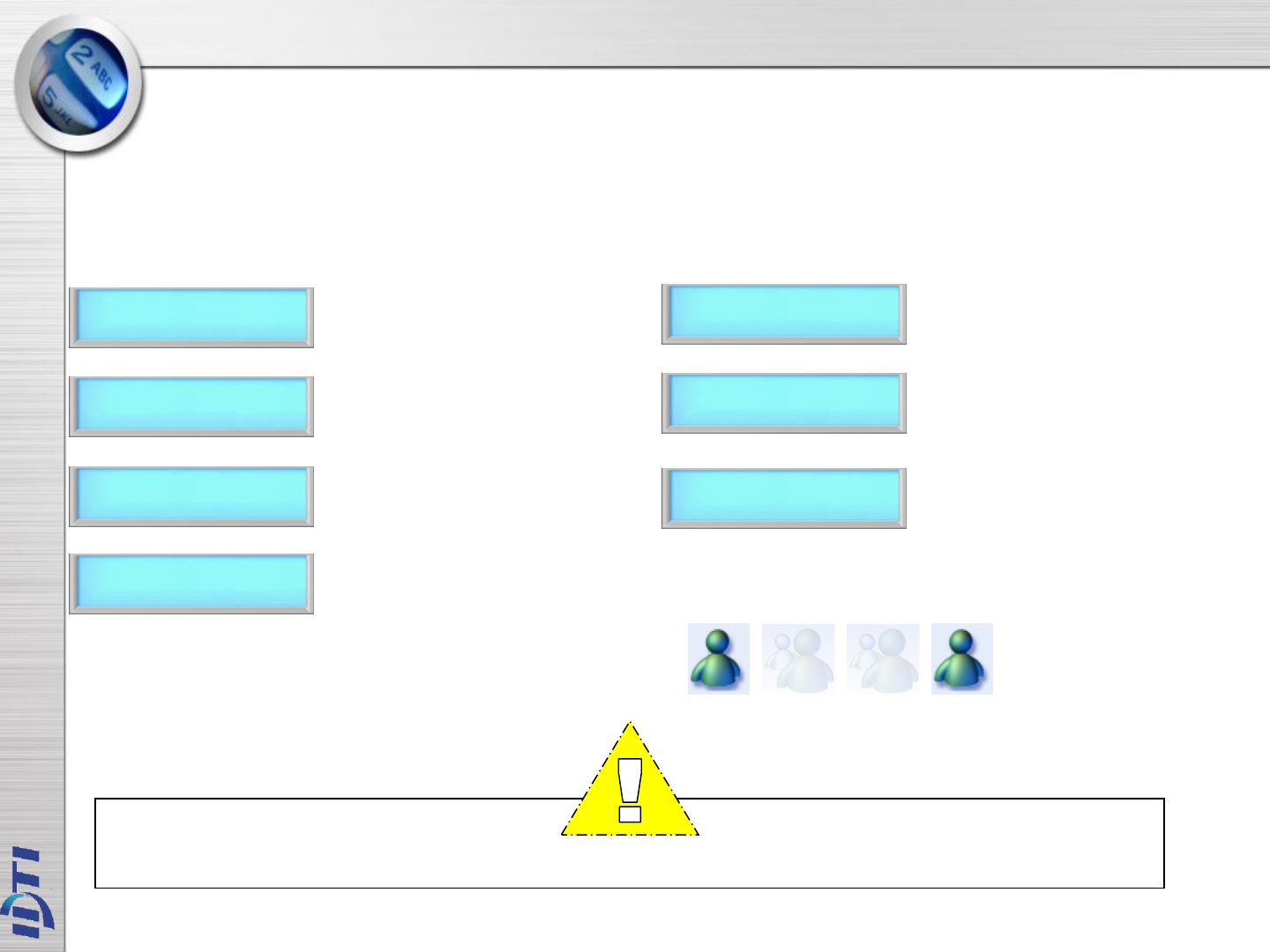
This command prevents an individual user from entering a selected empty security area unless at
least one other enrolled user is present. Once two enrolled users are logged into the area, other user
can come and go individually, as long as at least two people are in the area. Conversely, when
exiting, the last two occupants of the security area must exit out together. At no time will the system
allow less than two users to be in the area.
NOTE :
Two Man must be enabled in system setting. After enabling User Two Man option, go to main menu
5.SYSTEM SETTING/submenu 13.TWO MAN and enable the TWO MAN for system.
X O O X
1. Press F1/P key to enter system mode.
2. Press the # key to select EDIT USER
menu.
4. Press the # key enter USER TWO MAN
3. Press F1 or F2 key to select sub-menu
6. Press 1 to enable two man for this user
Press 2 to disable two man for this user
5. Enter user ID to apply two man
function followed by the key.
7. Edit completed. Press the # key to
continue editing another or press any
others to exit off the sub-menu
EDIT USER - 7.TWO MAN

USER LIST
EVENT DATA
FIRMWARE VERSION
FINGER VERSION
3. VIEW
VIEW – 1.USER LIST
MAIN PROGRAM
F1:UP F2:DN
3> VIEW
1.USER LIST
LIST 100000/0000
F1:UP F2:DN
3>VIEW USER
#:ENTER F4:ESC
3> VIEW USER
F1:UP F2:DN
NOTE :
Viewing System User List
The System User List will display the following information:
. The user's PIN (User ID)
. The user's name
. The user's administrator status
. The user's template location in memory
LIST VIEW EXIT
CONT:# STOP:ANY
At any time, you can view a list of all users of the system. The list can be an overall enrollment list of all
users in the system, or it can be a list of the individual users that are physically enrolled on any individual
fingerprint reader. Total number of users are 12,000.
100000/0001 (U)
12345678
100000/00001 (U)
12345678
MEMORY LOCATION
TOTAL NUMBER OF USERS
USER ID
USER LEVEL
FINGER : REG 4
CARD : 01FE0002
NAME
IDTi
TOTAL NUMBER REGISTERED
TEMPLATE
REGISTERED CARD
NUMBER
USER DISPLAY NAME
DETAIL VIEW KEY SCROLL UP KEY SCROLL DOWN KEY
1. Press F1/P key to enter system mode.
2. Press the # key to select VIEW
USER menu.
4. Press the # key enter USER LIST
3. Press F1 or F2 key to select sub-menu
6. Press F3 key to view detail view of user
Press F4 key to exit off the sub-menu
5. Press F1/P key to scroll up the user list
Press F2 key to scroll down the user list
7. View Exit. Press the # key to
continue viewing another or press any
others to exit off the sub-menu
61400/01526 2004
08.30 12:30:30
NOTE :
Viewing System Event Log
The System Event List will display the following information:
. The date of event occurrence
. The time of event occurrence
. The total number of event log
3> VIEW USER
2.EVENT DATA
614000/01525
F1:UP F2:DN
LIST VIEW EXIT
CONT:# STOP:ANY
61400/01526
NONE EVENT
At any time, you can view all transaction of event logs of the system. A record created that contains
pertinent information about an occurrence in the access control and monitoring system.
614000/01526 2004
08.30 12:30:30
MAIN PROGRAM
F1:UP F2:DN
3>VIEW USER
#:ENTER F4:ESC
3> VIEW USER
F1:UP F2:DN
ACCESS GRANTED
0001
CURRENT MEMORY LOCATION
TOTAL MEMORY
MONTH & DATE
EVENT
EVENT
YEAR
EVENT TIME
USER ID
1. Press F1/P key to enter system mode.
2. Press the # key to select VIEW
USER menu.
4. Press the # key to enter view EVENT
3. Press F1 or F2 key to select sub-menu
6. Press F3 key to view event data
Press F4 key to exit off the sub-menu
5. Following event log will appear.
Press F1 to scroll up the event log
Press F2 key to scroll down the event log
7. View Exit. Press the # key to
continue viewing another event or press
any others to exit off the sub-menu
VIEW – 2.EVENT
CURRENT MEMORY LOCATION
DETAIL VIEW KEY SCROLL UP KEY SCROLL DOWN KEY
MAIN PROGRAM
F1:UP F2:DN
3> VIEW
3.FIRMWARE
BSC-101 VER 1.13
2005. 01. 12
3>VIEW USER
#:ENTER F4:ESC
3> VIEW USER
F1:UP F2:DN
LIST VIEW EXIT
CONT:# STOP:ANY
This is to view the current firmware version of ISC-101A. Other ways to verify the firmware is to resetting
the device. When first booting up, firmware version will display.
VIEW FRIMWARE VERSION
1. Press F1/P key to enter system mode.
2. Press the # key to select VIEW
USER menu.
4. Press the # key to enter FIRMWARE
VERSION
3. Press F1 or F2 key to select sub-menu
5. Current firmware version number will
display
Press F4 key to exit off the sub-menu
6. Press # key to view firmware again
Press any other key to exit.
VIEW – 3.FIRMWARE

DELETE SINGLE USER
DELETE ALL USER
4. DELETE USER

DELETE - 1. SINGLE & 2.ALL
Deleting a fingerprint template from a reader will prevent that template from being granted access to the
location via the reader. Any fingerprint template can be removed from a fingerprint reader, including
administrative and the last remaining fingerprint template on the reader. Templates can be deleted by a
single user or all users including administrative templates.
1 – 16 DIGITS
ENTER USER ID
ENTER USER ID
12345678
DELETE COMPLETED
CONT:# STOP:ANY
MAIN PROGRAM
F1:UP F2:DN
4> DELETE USER
#:ENTER F4:ESC
4> DELETE USER
1.SINGLE USER
4> DELETE USER
F1:UP F2:DN
DELETE : ‘#’
CANCEL :’ANY’
DELETING……
>>>>
DELETE COMPLETED
F1:UP F2:DN
MAIN PROGRAM
F1:UP F2:DN
4> DELETE USER
#:ENTER F4:ESC
4> DELETE USER
2.ALL USER
4> DELETE USER
F1:UP F2:DN
DELETE SINGLE USER DELETE ALL USER
1. Press F1/P key to enter system mode.
2. Press the # key to select DELETE
USER menu.
4. Press the # key to enter delete
SINGLE USER
5. Enter in user ID to be deleted as
shown below
6. Enter in user ID from 1 to 16 digits
3. Press F1 or F2 key to select sub-menu
7. Delete completed.
Press # key to delete single user again
Press any other key to exit
1. Press F1/P key to enter system mode.
2. Press the # key to select DELETE
USER menu.
4. Press the # key to enter delete ALL
USER
5. Press the # key to enter delete All User.
Press any other key to cancel
6. Deleting. Please wait....
3Press F1 or F2 key to select sub-menu
7. Delete completed.

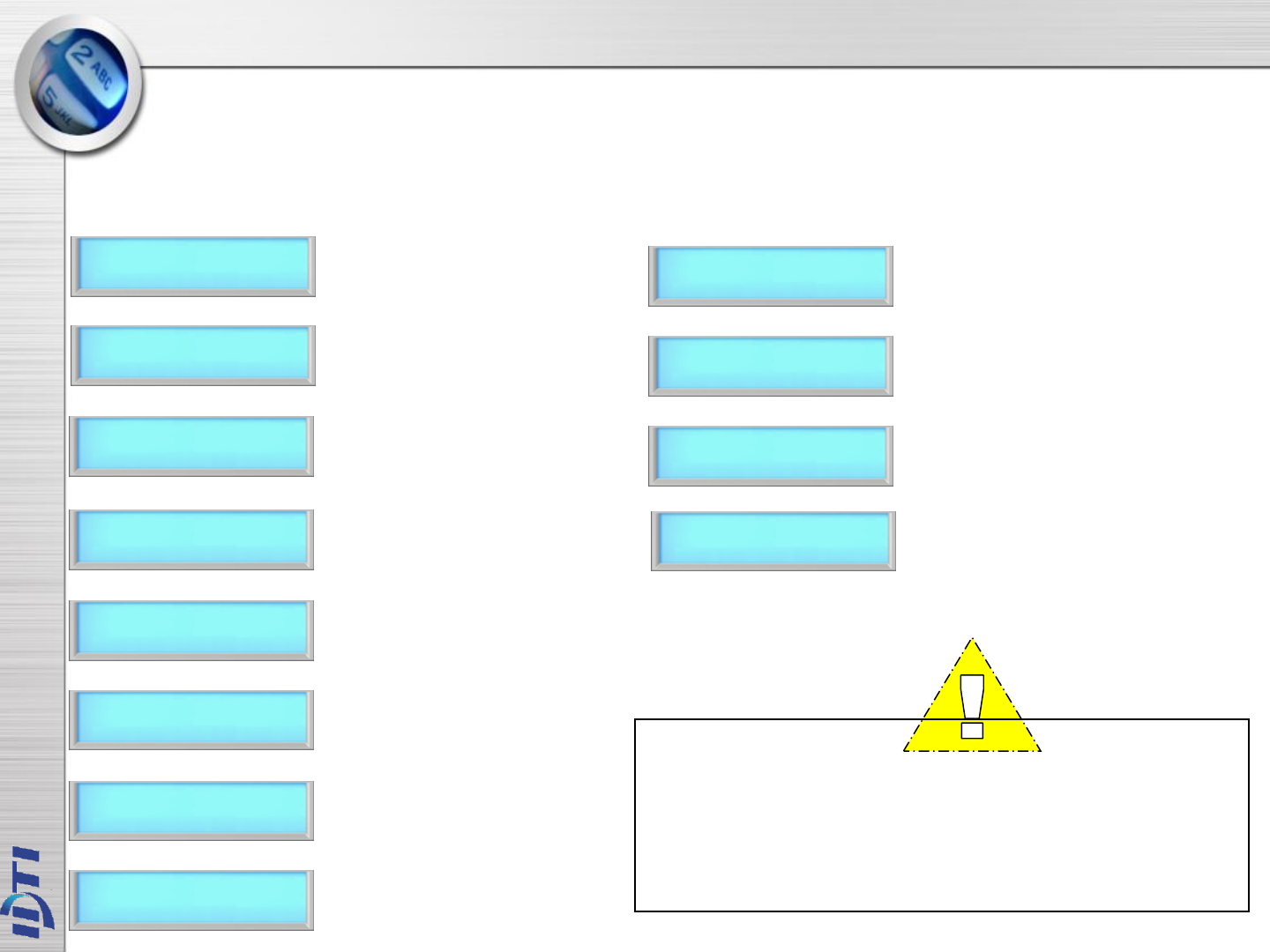
SYSTEM SETUP – MAIN MENU 5
1.TIME ………………………………………………………………….……...28
2.OPERATING MODE ………………………………………….…………..29
3.RE-LOCK TIME & 4.ADDRESS ………………………………………….30
5.COM.PASSWORD & 6.SITE CODE ……………………………………….31
7.SYSTEM RESET & 8.EVENT RESET ……………………………………32
9.COM.SPEED & 10.DOOR RELAY …..….…………………………………33
11.TWO MAN & 12.ANTIPASS …………………………………………..…...34
13.DURESS ………………………………………………………………..…....35
14.DATE FORMAT…………………………………………………………….36
15. CUSTOM DISPLAY………………………………………………………...37
16. LCD LIGHT….………………………………………………………….….38
17. CONCEAL PIN..…………………………………………………………...39
18. EXTERNAL RELAY BOARD ………….…………………………………40
19. LOCK DOWN ……………………………………………..….……….……41
20. ATTENDENCE ……………………………………………………………42
SENSOR SETUP – MAIN MENU 6
1. INPUT TYPE ………………………..……………………………………..44
2. FUNCTION …………………………………………………..……………45
ALARM SETUP – MAIN MENU 7
1. ALARM SETUP 1 …………………………………………………………..47
2. ALARM SETUP 2 .…………………………………………………………48
CHAPTER 2

TIME TWO MAN
OPERATING MODE ANTIPASS
RE-LOCK TIME DURESS
ADDRESS DATE FORMAT
COMMUNICATION PASSWORD CUSTOM DISPLAY
SITE CODE LCD LIGHT
SYSTEM RESET CONCEAL PIN
EVENT RESET LOCK DOWN
COM. SPEED ATTENDENCE
DOOR RELAY
5. SYSTEM SETUP
SYSTEM SETUP – 1.TIME
5> SYSTEM SETUP
1.TIME
YEAR:MON:DAY
2004 : 07 : 05
HOUR:MIN:SEC
20 : 20 : 20
1:SUN .. 7:SAT
SELECT 1-7
MAIN PROGRAM
F1:UP F2:DN
5> SYSTEM SETUP
#:ENTER F4:ESC
5> SYSTEM SETUP
F1:UP F2:DN
1:SUN ..7:SAT
[FRI] ENTER ‘#’
SETUP SOMPLETED
F1:UP F2:DN
ISC-101A features an internal clock that provides the date and time for all logged events. This section
discusses how to set the date and time that ISC-101A uses for event logging. To set the current time,
access the menu system and follow these steps.
NOTE :
Time format can be displayed in 3 types. Asian Time, European
Time and American Time. After setting the current time, go to
page and customized the time display option to view local time
display.
Select the day of week:
Sunday – 1
Monday – 2
Tuesday – 3
Wednesday – 4
Thursday – 5
Friday – 6
Saturday – 7
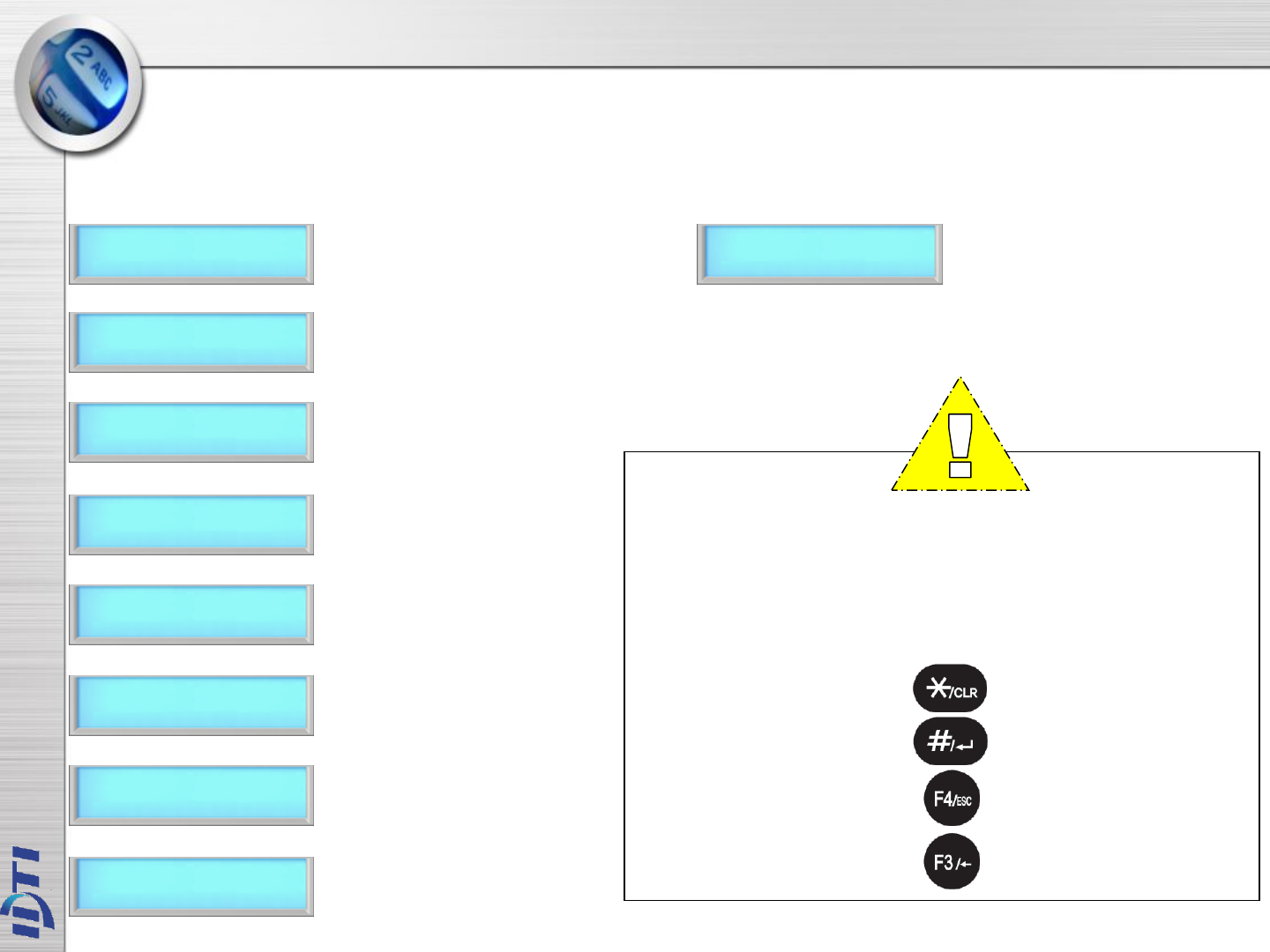
CLEAR KEY
ENTER KEY
ESCAPE KEY
BACK SPACE KEY
1. Press F1/P key to enter system mode.
2 Press the # key to select SYSTEM
SETUP menu.
4. Press the # key to enter system Time
5. Enter current date followed by the #
key
6. Enter current time followed by the #
key
3. Press F1 or F2 key to select sub-menu
9. Set up has completed
7. Select day of the week. Press 1
through 7 to enter day of the week.
Refer to NOTE
8. Press the # key to confirm.

SYSTEM SETUP – 2.OPERATING MODE
OPEN
F1:UP F2:DN
ID & FP
F1:UP F2:DN
CARD / FP
F1:UP F2:DN
ID & FP / CD
F1:UP F2:DN
FP (ID&FP)
F1:UP F2:DN
ID & CD & FP
F1:UP F2:DN
CLOSED
F1:UP F2:DN
TESTING MODE
F1:UP F2:DN
CARD or FINGERPRINT : User can access the device by either card or fingerprint. When operating in this mode,
simply enter user card or fingerprint to the device.
PIN & FINGERPRINT or CARD : In this mode, user can access the device by PIN with fingerprint or just a card.
To operate in this mode, user must enter PIN first before entering finger or present user card.
PIN & CARD & FINGERPRINT : User must use all three tokens to gain access. This is the highest security mode
available in BSC-101A. To operate in this mode, first enter user PIN and press the # key, then present user
card followed by user fingerprint.
OPERATION MODE :
ISC-101A has 11 total operating mode. List is the detail view of the operating modes available in ISC-101A.
PIN or CARD or FINGERPRINT (ANY MODE) : User can access the device by any of the available tokens. This is
the most convenient but lowest security mode in BioScan. To operate in this mode, simply use any one of the
token.
FINGER ONLY or ID & FINGER : Fingerprint reader will be the only accessible device and user must enter using
fingerprint. This is an 1:1 or 1:N verification. User also have an option to again access by entering user PIN
and entering user fingerprint for faster.
PIN & Fingerprint : User must enter using user PIN & Fingerprint to access the unit. To operate in this mode,
enter user PIN and press the # key followed by user fingerprint.
ALWAYS OPEN : Access point will stay open for an emergency such as fire.
ALWAYS CLOSE : Access point will stay
locked for an emergency such as intrusion. Testing Mode : It will be a good idea
to test the unit in this mode when
first installed.
CD & FP
F1:UP F2:DN
Card & Fingerprint : User must enter using user card & Fingerprint to access the unit. To operate in this mode,
enter user card followed by user fingerprint.
ID&FP / ID&CD
F1:UP F2:DN
PIN & Fingerprint or PIN & Card : In this mode user can access the device by entering user PIN and fingerprint
or user PIN and card. This mode is useful when networked with a proximity readers.
ID&FP / CD&FP
F1:UP F2:DN
PIN & Fingerprint or Card & Fingerprint : In this mode user can access the device by using PIN with fingerprint
or card with fingerprint.
ID / CD / FP
F1:UP F2:DN

SYSTEM SETUP – 2.OPERATING MODE
5> SYSTEM SETUP
2.OPERATING MODE
SELECT MODE
F1:UP F2:DN
[CD] [FP]
F1:UP F2:DN
SETUP COMPLETED
F1:UP F2:DN
This section provides information about how to choose the operation mode. ID/CD/FP (ALL) is the
default operating mode.
SELECT MODE
F1:UP F2:DN
List of operating modes to choose.
Select from the following list.
MAIN PROGRAM
F1:UP F2:DN
5> SYSTEM SETUP
#:ENTER F4:ESC
5> SYSTEM SETUP
F1:UP F2:DN
1. Press F1/P key to enter system mode.
2. Press the # key to select SYSTEM
SETUP menu.
4. Select OPERATING MODE followed
by the # key
5. Press F1 key to scroll up the mode menu
Press F2 key to scroll down the mode menu
6. Press the # key to select operating
mode.
3. Press F1 or F2 key to select sub-menu
7. Setup completed
OPEN
F1:UP F2:DN
CARD / FP
F1:UP F2:DN
ID & FP / CD
F1:UP F2:DN
CLOSED
F1:UP F2:DN
ID&FP / ID&CD
F1:UP F2:DN
ID / CD / FP
F1:UP F2:DN
TESTING MODE
F1:UP F2:DN
SYSTEM SETUP – 3.RE-LOCK TIME, 4.ADDRESS
5> SYSTEM SETUP
3.RE-LOCK TIME
LOCK TIME SETUP
C : 04: S :
MAIN PROGRAM
F1:UP F2:DN
5> SYSTEM SETUP
#:ENTER F4:ESC
5> SYSTEM SETUP
F1:UP F2:DN
SETUP SOMPLETED
F1:UP F2:DN
3. RE-LOCK TIME : This is the maximum duration that the lock release relay will be energized. The relay
is de-energized if the door opens before this time has expired. The lock time can be set in the range
01~99 seconds. You cannot set a lock time of 0 seconds. Default is 3~5 seconds.
4. ADDRESS – Communication options allow ISC-101A to communicate with a PC and other door
control equipment. In network applications, ISC-101A units communicate with a connected PC. This
requires each unit to have a unique identification code. To assign a Network ID, follow the steps listed
below: Repeat this procedure for each networked unit, assigning a unique identification code to each
unit. Default address is set to 1.
5> SYSTEM SETUP
4.ADDRESS
1 .. 14 setup
C : 01 s :
MAIN PROGRAM
F1:UP F2:DN
5> SYSTEM SETUP
#:ENTER F4:ESC
1> SYSTEM SETUP
F1:UP F2:DN
SETUP SOMPLETED
F1:UP F2:DN
RE-LOCK TIME ADDRESS
1. Press F1/P key to enter system mode.
2 Press the # key to select SYSTEM
SETUP menu.
4. Press the # key to enter Re-Lock Time
5. Key in Re-Lock Time from 1 to 99 second
followed by the # key. C stands for current
set time, sample show 4 second.
3. Press F1 or F2 key to select sub-menu
6. Setup has completed
1. Press F1/P key to enter system mode.
2. Press the # key to select SYSTEM
SETUP menu.
4. Press the # key to enter ADDRESS
5. Key in from 1 ~ 14 followed by the #
key. You can assign network ID from 1
through 14. C stands for current setting.
Default setting is set to address 1.
3. Press F1 or F2 key to select sub-menu
6. Setup has completed
SYSTEM SETUP – 5.COM. PASSWORD, 6.SITE CODE
5> SYSTEM SETUP
5.COM. PASSWORD
0-99999999 setup
c: FFFFFFFF
MAIN PROGRAM
F1:UP F2:DN
5> SYSTEM SETUP
#:ENTER F4:ESC
5> SYSTEM SETUP
F1:UP F2:DN
COM. PASSWORD
12345678
SETUP SOMPLETED
F1:UP F2:DN
COMMUNICATION
PASSWORD
5. COMMUNICATION PASSWORD : Communication password is used during network communication.
This safeguards the information sent during transmission and also from hacking the system.
6. SITE CODE : A site code, which is sometimes called a facility code, differentiates one users card
group from another. A facility code is an integral code that is programmed into the card at the time of
manufacture. Facility codes overcome this limitation adding a second code which is checked at the
reader.
1. Press F1/P key to enter system mode.
2. Press the # key to select SYSTEM
SETUP menu.
4. Press the # key to enter COM. PASSWORD
5. Current password is displayed. Enter
new password as show in next figure
3. Press F1 or F2 key to select sub-menu
7. Setup has completed
5> SYSTEM SETUP
6.SITE CODE
0 ..255 SETUP
C : 255 S :
MAIN PROGRAM
F1:UP F2:DN
5> SYSTEM SETUP
#:ENTER F4:ESC
5> SYSTEM SETUP
F1:UP F2:DN
SETUP SOMPLETED
F1:UP F2:DN
SITE CODE
1. Press F1/P key to enter system mode.
2. Press the # key to select SYSTEM
SETUP menu.
4. Press the # key to enter SITE CODE.
5. "C" stands for current site code
which is 255. Enter from 0 to 255 and
press the # key. Default setting is 255
3. Press F1 or F2 key to select sub-menu
6. Setup has completed
1.EM.S. 26 Bit
F1:UP F2:DN
2.HID.S. 26 Bit
F1:UP F2:DN
3.HID.Full 26Bit
F1:UP F2:DN
4.HID.IDTi 34Bit
F1:UP F2:DN
5.MIFARE. 32 Bit
F1:UP F2:DN
5. Select the card type followed by
the # key
1. EM 26bit : 0~255
2. HID Standard 26bit : 0~255
3. HID Full binary 26bit : None
4. HID 34bit : 0~65535
5. Mifare 32 bit : None
6. Key in the 8 digit password and press the #
key to confirm new password
SYSTEM SETUP – 7.SYSTEM RESET, 8.EVENT RESET
5> SYSTEM SETUP
7.SYSTEM RESET
SYSTEM RESET ?
YES:1 NO:ANY
MAIN PROGRAM
F1:UP F2:DN
5> SYSTEM SETUP
#:ENTER F4:ESC
5> SYSTEM SETUP
F1:UP F2:DN
SYSTEM RESET
>>>
COMPLETED
F1:UP F2:DN
7. System Reset : There are two databases inside the ISC-101A, System Database & Event Database. The
System Database stores the system setting information. When executed, the system reset will restore the
factory default setting.
8. Event Reset : The Event Database only stores the access records. It does not contain any system
information. When executed, event reset will erase all event logs that are stored in the memory.
5> SYSTEM SETUP
8.EVENT RESET
EVENT RESET ?
YES:1 NO:ANY
MAIN PROGRAM
F1:UP F2:DN
5> SYSTEM SETUP
#:ENTER F4:ESC
5> SYSTEM SETUP
F1:UP F2:DN
EVENT RESET
>>>
COMPLETED
F1:UP F2:DN
SYSTEM RESET EVENT RESET
EVENT RESET :1
INDEX RESET :2
INDEX RESET ?
YES:1 NO:ANY
1. Press F1/P key to enter system mode.
2. Press the # key to select SYSTEM
SETUP menu.
4. Press the # key to enter SYSTEM RESET
5. Press 1 to reset system
Press any other key to cancel
6. System resetting message. This may take
few seconds to a minute depending on the
size of the database
3. Press F1 or F2 key to select sub-menu
7. System reset has completed
1. Press F1/P key to enter system mode.
2. Press the # key to select SYSTEM
SETUP menu.
4. Press the # key to enter SEVENT
RESET.
6. Press 1 key to reset
Press any other keys to cancel
7. Event resetting message. This may take
few seconds to a minute depending on
the size of the database
3. Press F1 or F2 key to select sub-menu
8. Event Reset has finished
5. Press 1 key to reset event
Press 2 key to reset index
SYSTEM SETUP – 9. COM. SPEED, 10. DOOR RELAY
5> SYSTEM SETUP
10.COM. SPEED
SELECT SPEED
F1:UP F2:DN
MAIN PROGRAM
F1:UP F2:DN
5> SYSTEM SETUP
#:ENTER F4:ESC
5> SYSTEM SETUP
F1:UP F2:DN
1. 4800 b-rate
F1:UP F2DN
SETUP COMPLETED
F1:UP F2:DN
9. COM.SPEED – This command sets the baud rate that the ISC-101A will communicate with the device
connected to its serial port. The baud rate change will become effective immediately upon completion
of the command. Default baud rate is 19,200.
10. DOOR RELAY – The relay output is Normally Open (N.O.), and toggles shorted when triggered by an
event, such as an authentication or ID failure. The relay can be used to send power to switched items
like electric door strikes, door handles, magnetic hold locks1, or indicators.
2. 9600 b-rate
F1:UP F2DN
3. 19200 b-rate
F1:UP F2DN
4. 38400 b-rate
F1:UP F2DN
6. Press the # key to select the communication speed
5> SYSTEM SETUP
11.DOOR (RELAY)
MAIN PROGRAM
F1:UP F2:DN
5> SYSTEM SETUP
#:ENTER F4:ESC
5> SYSTEM SETUP
F1:UP F2:DN
RELAY1Sel 1-Door
2-Alarm 3-L.D
SETUP COMPLETED
F1:UP F2:DN
COMMUNICATION SPEED DOOR RELAY
6. 1 for Door, 2 for Alarm and 3 for
Lock Down.
1. Press F1/P key to enter system mode.
2. Press the # key to select SYSTEM
SETUP menu.
4. Press the # key to enter COM.SPEED.
3. Press F1 or F2 key to select sub-menu
5. Press F1 key to scroll up the list
Press the F2 key to scroll down the list
7. Setup has completed
1. Press F1/P key to enter system mode.
2. # 키를 눌러 SYSTEM SETUP(시스템
설정) 메뉴를 선택.
4. Select DOOR(RELAY) followed by the
# key
3. Press F1 or F2 key to select sub-menu
7. Setup has completed
SYSTEM SETUP – 11. TWO MAN, 12. ANTIPASS
5> SYSTEM SETUP
12.TWO MAN
ENABLE TWOMAN
1:YES 2:NO
ENTER NUM 1-99
C : 20 S :
SETUP COMPLETED
F1:UP F2:DN
11. TWO MAN : This commend prevents an individual user from entering a selected empty security
area unless at least one other enrolled user is present. Once two enrolled users are logged into the
area, other user can come and go individually, as long as at least two people are in the area.
Conversely, when exiting, the last two occupants of the security area must exit out together. At no
time will the system allow less than two users to be in the area.
12. ANTIPASS : Anti pass-back is used to stop two people from using one card to gain access. If
access is denied because of this, this will result in an alarm message to the printer. It may also
result in a relay being energized if you have programmed one to do so. This is a system anti-pass
setting and user anti-pass setting also must be enabled in order for it to work properly.
5> SYSTEM SETUP
13.ANTIPASS
ENABLE ANTIPASS?
1:YES 2:NO
SETUP COMPLETED
F1:UP F2:DN
5> SYSTEM SETUP
F1:UP F2:DN
1. Press F1/P key to enter system mode.
4. Press the # key to enter Two Man
3. Press F1 or F2 key to select sub-menu
6. This is the time limit for the second user
to make verification to the reader after first
user has been verified. "C" Stands for
current setting. Key in from 1 to 99
seconds and press the # key
5> SYSTEM SETUP
#:ENTER F4:ESC
2. Press the # key to select SYSTEM
SETUP menu.
5> SYSTEM SETUP
F1:UP F2:DN
MAIN PROGRAM
F1:UP F2:DN
5. Press 1 key to enable two man
Press 2 key to disable two man
7. Setup has completed
4. Press the # key to enter Antipass
3. Press F1 or F2 key to select sub-menu
5. Press 1 key to enable anti pass
Press 2 key to disable anti pass
6. Setup has completed
1. Press F1/P key to enter system mode.
5> SYSTEM SETUP
#:ENTER F4:ESC
2. Press the # key to select SYSTEM
SETUP menu.
MAIN PROGRAM
F1:UP F2:DN
TWO MAN ANTI PASS

SYSTEM SETUP – 13. DURESS
ENTER FUNCTION
F2 :
Duress is a condition whereby a user may be confronted by an intruder in an effort to gain access
to a secure area. The user can "secretly" signal security that he is entering the secure area under
"duress" through the implementation of a duress feature. This function must be used with a
function key in order to work
5> SYSTEM SETUP
13.DURESS
ENABLE DURESS?
YES: 1 NO:2
MAIN PROGRAM
F1:UP F2:DN
5> SYSTEM SETUP
#:ENTER F4:ESC
5> SYSTEM SETUP
F1:UP F2:DN
ENTER NUM F2,F4
SETUP COMPLETED
F1:UP F2:DN
1. Press F1/P key to enter system mode.
4. Press the # key to enter DURESS
3. Press F1 or F2 key to select sub-menu
6. Key in F2 or F4 to assign duress key.
For now we will key in F2 key
2. Press the # key to select SYSTEM
SETUP menu.
5. Press 1 key to enable duress
Press 2 key to disable duress
8. Setup completed
7. Key in from 0 to 9 followed by # key.
SYSTEM SETUP – 14. DATE FORMAT
5> SYSTEM SETUP
14.DATE FORMAT
SELECT DISPLAY
F1:UP F2:DN
MAIN PROGRAM
F1:UP F2:DN
5> SYSTEM SETUP
#:ENTER F4:ESC
5> SYSTEM SETUP
F1:UP F2:DN
1: ASIA
YYYY.MM.DD
EDIT COMPLETED
F1:UP F2:DN
2: USA
MM.DD.YYYY
3: EUROPE
DD.MM.YYYY
4: CUSTOM1
Message DD/MM
5: CUSTOM1
Message MM/DD
NOTE :
BSC 2004.09.09
17:50:30 [THU]
BSC 08.30.2004
12:30:30 [THU]
BSC 30.08.2004
12:30:30 [THU]
IDTi
12:30:30 30/08
IDTi
12:30:30 08/30
ASIA Time display format
USA Time display format
EUROPE Time display format
CUSTOM 1 Time display format with Europe date
format. Date is displayed before the month
CUSTOM 2 Time display format with American date
format. Month is displayed before the date
ISC-101A features option to choose time format which are available in Asia time, USA time, and Europe
time. This is where user can customize time format. This section discusses how to choose time format.
1. Press F1/P key to enter system mode.
2. Press the # key to select SYSTEM
SETUP menu.
4. Press the # key to enter DATE FORMAT
3. Press F1 or F2 key to select sub-menu
5. Press F1 key to scroll up the list
Press F2 key to scroll down the list
6. Select the right time format for your region
7. Time format has been set
SYSTEM SETUP – 15. CUSTOM DISPLAY
EDIT DISPLAY
IDTi
5. Key in alphabet and press the F1 key
to move on to the next letter. To get an
lowercase, continue pressing the key
until the lowercase letter appears.
6. If the message is longer than 16
digits, press 1 key to continue on
writing the message. Otherwise press 2
to end writing custom message
EDIT COMPLETED
F1:UP F2:DN
5> SYSTEM SETUP
15.CUSTOMDISPLAY
MAIN PROGRAM
F1:UP F2:DN
5> SYSTEM SETUP
#:ENTER F4:ESC
5> SYSTEM SETUP
F1:UP F2:DN
EDIT CONTINUE?
1: YES 2: NO
EDIT DISPLAY
IDTi
7. Continue on writing the message
NOTE :
NAVIGATION KEYS
SPACE KEY
CLEAR KEY ENTER KEY
ESCAPE KEY
BACK SPACE KEY
ISC-101A features option to customize the display. BSC-101A Allows up to 32 characters to be displayed.
This is where user can customize main display window. This section discusses how to edit custom display.
1. Press F1/P key to enter system mode.
2. Press the # key to select SYSTEM
SETUP menu.
4. Press the # key to enter CUSTOM
DISPLAY
3. Press F1 or F2 key to select sub-menu
Ex) Edit “IDTi C”
8. Finished editing the custom message
3 times. 1time. 1time. 6 times 3times. 1time.
I D T i Space C
No of Key Press
SYSTEM SETUP – 16. LCD LIGHT
5> SYSTEM SETUP
16.LCD LIGHT
1: DEFAULT
LCD LIGHT TIME
MAIN PROGRAM
F1:UP F2:DN
5> SYSTEM SETUP
#:ENTER F4:ESC
1> SYSTEM SETUP
F1:UP F2:DN
ISC-101A allows you to choose whether the display will be illuminated or unlit. By default, the display is lit
for 5 seconds when used. Illuminating the display allows for easier viewing in darker areas while leaving the
display unlit conserves power. This section provides information about how to set illumination options for
the ISC-101A's display unit.
3. CUSTOMIZE
LCD LIGHT TIME
S HOUR:MIN:SEC
: :
7. Define the start time of LCD. LCD will
turn on according to this time setting.
Key in military time format.
E HOUR:MIN:SEC
: :
8. Define the end time of LCD. LCD will
turn off according to this time setting.
Key in military time format.
EDIT COMPLETED
F1:UP F2:DN
NOTE :
3 types of LCD option:
Default : LCD will stay lit for 5 seconds.
Always ON : LCD will illuminated all times.
Customize : You can set schedule time for LCD to turn on and
turn off.
6. Press the # key to set it as customize
Press F1 to scroll up the menu
Press F2 to scroll down the menu
1. Press F1/P key to enter system mode.
2. Press the # key to select SYSTEM
SETUP menu.
4. Press the # key to enter LCD LIGHT
3. Press F1 or F2 key to select sub-menu
6. Finished editing LCD back light time
5. Press the # key to set it as default time
Press F1 to scroll up the menu
Press F2 to scroll down the menu
SYSTEM SETUP – 17. CONCEAL PIN
5> SYSTEM SETUP
17.CONCEAL PIN
CONCEAL SETUP
1:YES 2:NO
SETUP COMPLETED
F1:UP F2:DN
5> SYSTEM SETUP
F1:UP F2:DN
5. Press 1 key to enable conceal PIN
Press 2 key to cancel the conceal PIN
4. Press the # key to enter CONCEAL PIN
CONCEAL CANCEL
1:YES 2:NO
(U) WELCOME
*****
(U) WELCOME
00002
ENTER USER ID
*****1
Result of authentication
Actual view during entrance
Concealed User PIN View
MAIN PROGRAM
F1:UP F2:DN
5> SYSTEM SETUP
#:ENTER F4:ESC
1. Press F1/P key to enter system mode.
2. Press the # key to select SYSTEM
SETUP menu.
Normal View
3. Press F1 or F2 key to select sub-menu
6. Setup has completed
5. Press 1 key to cancel conceal PIN
Press 2 key to enable the conceal PIN
Enabled Already
ISC-101A allows you to conceal user PIN when entering the device. To hide user PIN when entering the
device, follow the instructions below.
SYSTEM SETUP – 19. LOCK DOWN
5> SYSTEM SETUP
19. LOCK DOWN
LOCK DN ENABLE ?
1:YES 2:NO
SETUP COMPLETED
F1:UP F2:DN
5> SYSTEM SETUP
F1:UP F2:DN
LOCK DN DISABLE ?
1:YES 2:NO
MAIN PROGRAM
F1:UP F2:DN
5> SYSTEM SETUP
#:ENTER F4:ESC
1. Press F1/P key to enter system mode.
2. Press the # key to select SYSTEM
SETUP menu.
5. Press 1 key to enable lockdown
Press 2 key to disable lockdown
4. Press the # key to enter LOCK DOWN
3. Press F1 or F2 key to select sub-menu
7. Setup has completed
5. Press 1 key to disable lockdown
Press 2 key to enable lockdown
ISC-101A features option to use a auxiliary relay to arm/disarm an external alarm system called the
lockdown. This section discusses how to enable lockdown device.
Select Main Menu
5. SYSTEM SETUP
, Sub Menu
10.DOOR (RELAY)
, and set to L.D(Lock Down).
Select Main Menu
7. SENSOR SETUP
– Sub Menu
2.FUNCTION
and set the function of sensor to Lock
Down
1
2
3
FUNC KEY NABLE ?
1:YES 2:NO
6. Press 1 key to enable function key
Press 2 key to disable function key
Enabled Already
SYSTEM SETUP – 20. ATTENDENCE
5> SYSTEM SETUP
20.ATTENDENCE
ATTENDENCE SETUP
1:YES 2:NO
SETUP COMPLETED
F1:UP F2:DN
5> SYSTEM SETUP
F1:UP F2:DN
5. Press 1 to setup attendance
Press 2 to cancel setup
4. Press the # key to enter ATTENDENCE
IN 2005.12.27
16:17:59 [TUE]
MAIN PROGRAM
F1:UP F2:DN
5> SYSTEM SETUP
#:ENTER F4:ESC
1. Press F1/P key to enter system mode.
2. Press the # key to select SYSTEM
SETUP menu.
3. Press F1 or F2 key to select sub-menu
6. Setup has completed
ISC-101A features option to display IN or OUT when function keys are used. User must be aware of the
current attendance mode that is displayed in the standby display. Last used attendance mode will be the
default mode until the next mode is used. If F2-0 is used the last time, then unless second user uses a
different function key, it will show as F2-0 even if second user do not press any function key.
OUT 2005.12.27
16:17:59 [TUE]
E-IN 2005.12.27
16:17:59 [TUE]
E-OUT 2005.12.27
16:17:59 [TUE]
F2-0
F4-0
F2-1
F2-2
ATTEND
LEAVE
RETURN
OUT
(U) < I N > F2:0
123456
(U) < O U T > F4:0
123456
(U) < EX-IN> F2:1
123456
(U) < EX-OUT F2:2
123456
F2-0
F4-0
F2-1
F2-2
ATTEND
OUT
RETURN
OUT
Standby LCD Display
Access Granted Display

INPUT TYPE
FUNCTION
6. SENSOR SETUP

SENSOR SETUP – 1. INPUT TYPE
7> SENSOR SETUP
1.INPUT TYPE
SELECT SENSOR
ENTER NUM: 1-2
MAIN PROGRAM
F1:UP F2:DN
7> SENSOR SETUP
#:ENTER F4:ESC
7> SENSOR SETUP
F1:UP F2:DN
SENSOR1 N/O
1:N/O 2:N/C
SETUP COMPLETED
CONT:# STOP:ANY
The sensor inputs are factory defaulted to Normally Open (N.O.). This section show how to change the
sensor input to either N.O. or N.C.
1. Press F1/P key to enter system mode.
2. Press the # key to select
SENSORSETUP menu.
4. Press the # key to enter Input Type
5. Select from 1 though 2 followed by
the # key
3. Press F1 or F2 key to select sub-menu
7. Setup has completed
6. Press 1 key to N/O (stands for Normal Open)
Press 2 key to N/C (stands for Normal Close)
SENSOR SETUP – 2.FUNCTION
7> SENSOR SETUP
2.FUNCTION
SELECT SENSOR
ENTER NUM: 1-2
MAIN PROGRAM
F1:UP F2:DN
7> SENSOR SETUP
#:ENTER F4:ESC
7> SENSOR SETUP
F1:UP F2:DN
SENSOR1 1.EXIT
1:SETUP 2:CANCEL
SELECT FUNCTION
F1:UP F2:DN
1. EXIT
F1:UP F2:DN
2. ALARM
F1:UP F2:DN
3. FIRE ALARM
F1:UP F2:DN
4. LOCK
F1:UP F2:DN
5. DOOR CONTACT
F1:UP F2:DN
6. INTRUSION
F1:UP F2:DN
7. LOCK DOWN
F1:UP F2:DN
SLEECT FUNCTION
F1:UP F2:DN
SELECT SENSOR
ENTER NUM: 1-2
SENSOR1 1.EXIT
1:SETUP 2:CANCEL
SENSOR2 2.ALARM
1:SETUP 2:CANCEL
SETUP COMPLETED
CONT.:# STOP:ANY
Default set for 2 sensors Select function of sensor
These are the senor inputs found in ISC-101A control panel that control external devices. There are 2 sensor
inputs in ISC-101A and all of them can be programmed to handle different types of external sensors from
the system menu.
NOTE :
1. Press F1/P key to enter system mode.
2. Press the # key to select SENSOR
SETUP menu.
4. Press the # key to enter FUNCTION
5. Select from 1 though 2 followed by
the # key
3. Press F1 or F2 key to select sub-menu
8. Setup has completed
6. Default is set as EXIT. You can
customize the function as show in the
note
7. Press F1 key to scroll up the list of
functions
Press F2 key to scroll down the list . Refer
to note for the complete list of functions.
0. INACTIVE
F1:UP F2:DN

ALARM SETUP
7. ALARM SETUP

ALARM SETUP
There are six sensor inputs and 1 relay on ISC-101A. Relays is used for the lock, depending on the
configuration
There is no programming function for alarms what you program is what happens when a specific
alarm occurs. There are two things that can happen as a result of an alarm:
· an alarm may result in a message to the speaker (Buzzer).
· an alarm may also cause a relay to come on (Relay).
ISC-101A has an output to activate a sounder but also equipped with relays that can be controlled
from a command station, by some type of system activity. These sensor inputs & relays can allow
you to perform many functions such as motion sensor or as a means of interfacing with a home
automation system. Only the internal sensors will be activated unless other sensors are connected
and configured in Sensor Setup. Relay must be connected to use the alarm.

ALARM SETUP
8> ALARM SETUP
1.CASE OPEN
ALARM SETUP ?
1:SETUP 2: CANCEL
MAIN PROGRAM
F1:UP F2:DN
8> ALARM SETUP
#:ENTER F4:ESC
8> ALARM SETUP
F1:UP F2:DN
SETUP COMPLETED
F1:UP F2:DN
SELECT FUNCTION
F1:UP F2:DN
8> ALARM SETUP
1.CASE OPEN
BUZZER&RELAY
1.BUZZER&RELAY
BUZZER&RELAY
2.BUZZER ONLY
BUZZER&RELAY
3. RELAY ONLY
BUZZER&RELAY
4. INACTIVE
8> ALARM SETUP
2.INTRUSION
8> ALARM SETUP
3.FORCE OPEN
8> ALARM SETUP
4.ALARM SENSOR
8> ALARM SETUP
5.FIRE
8> ALARM SETUP
6.DURESS
8> ALARM SETUP
7.LINE TROUBLE
8> ALARM SETUP
8.BOLT OPEN
8> ALARM SETUP
10.LOCK HELD
8> ALARM SETUP
11.ALARM TIME
8> ALARM SETUP
12.ALARM OFF
8> ALARM SETUP
9.DOOR HELD
8> ALARM SETUP
F1:UP F2:DN
SELECT FUNCTION
F1:UP F2:DN
(Fig 1) List of the Alarm (Fig 2) List of the output
BUZZER&RELAY
1.BUZZER&RELAY
1. Press F1/P key to enter system mode.
2. Press the # key to select ALARM
SETUP menu.
4. There are total of 12 alarms. Refer to
Fig 1 Alarm List on the left for complete
list.
5. Press 1 key to setup Alarm
Press number 2 key to cancel.
3. Press F1 or F2 key to select sub-menu
8. Alarm setup finished.
6. Press F1 key to scroll up
Press F2 key to scroll down the list of
functions.
7. There are total of 4 sounder options.
Refer to fig 2 list of sounder options.
For now we will select 1 Buzzer & Relay
Buzzer and Relay will be activated
Buzzer will be activated
Relay will be activated
Alarm is inactive