IDENTIVE TECHNOLOGIES AMID2US00 Multi ISO HF Reader User Manual
IDENTIVE TECHNOLOGIES AG Multi ISO HF Reader
UserManual.wiki
>
IDENTIVE TECHNOLOGIES
>
AMID2US00 User Manual
User Manual
Navigation menu
Upload a User Manual
Namespaces
Wiki Guide
HTML
PDF
Info
Views
User Manual
Discussion / Help
Navigation
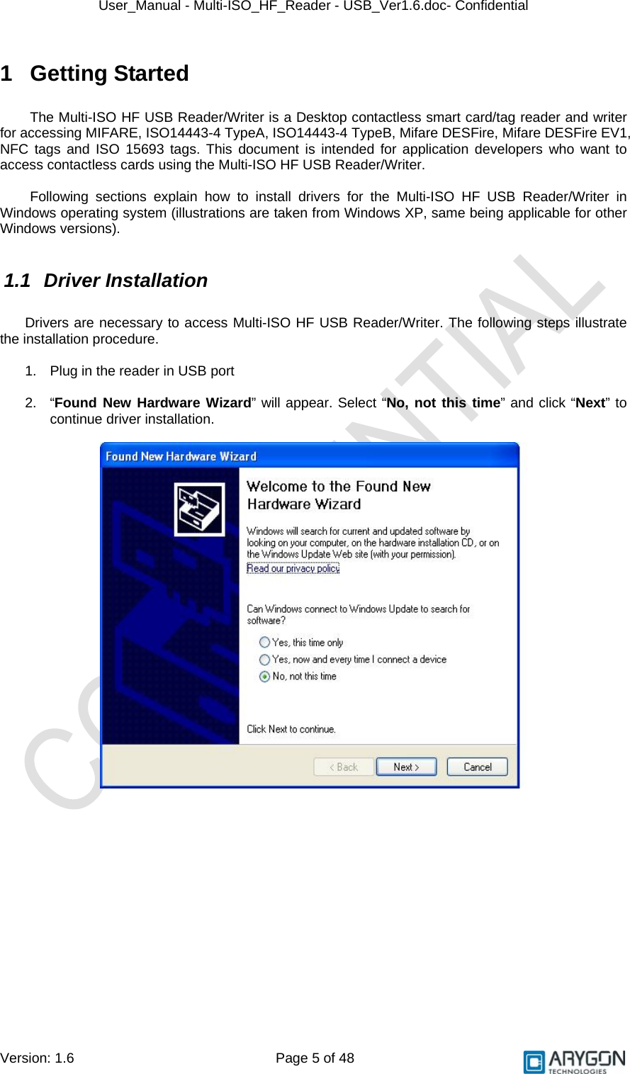
![User_Manual - Multi-ISO_HF_Reader - USB_Ver1.6.doc- Confidential Version: 1.6 Page 15 of 48 4 PCSC 2.0 “Multi-ISO HF USB Reader/Writer” can be accessed using the standard PCSC architecture for communicating with cards. This makes card access easy, as it uses the same communication procedure for all the cards. The Microsoft Developer Network (MSDN) library gives valuable information and a detailed description of all SCard APIs for communicating with the reader, through the Windows PCSC framework (WINSCARD APIs – Refer [R4]). 4.1 How to Access Contactless Cards via PCSC? Contactless cards can be easily accessed through PCSC using standard WINSCARD smart card API’s for card access. The following steps provide guidelines for using the PCSC compliant WINSCARD API’s to access cards using the Multi-ISO HF USB Reader/Writer. 4.1.1 Establish Context This is the first step. This API will initialize all other PCSC APIs and allocate all resources necessary for a smart card session. The SCardEstablishContext function establishes the resource manager context (the scope) within which database operations is performed. LONG SCardEstablishContext ( IN DWORD dwScope, IN LPCVOID pvReserved1, IN LPCVOID pvReserved2, OUT LPSCARDCONTEXT phContext); 4.1.2 List Readers The next step is to get a list of all PCSC readers connected to the system using the SCardListReaders function. Look for “Multi-ISO HF Reader – USB - 0000000000000001 0”, in the list returned. If multiple Multi-ISO HF USB Reader/Writers are connected to your system, they will be enumerated with different serial numbers. Example: “Arygon Multi-ISO 0000000000000001 0”, “Arygon Multi-ISO 0000000000000002 0”, could be the list returned when the following function is executed. LONG SCardListReaders (IN SCARDCONTEXT *phContext, IN LPCTSTR mszGroups, OUT LPTSTR mszReaders, IN OUT LPDWORD pcchReaders); Note: The OUT parameter phContext of SCardEstablishContext is used as in parameter for this API.](https://usermanual.wiki/IDENTIVE-TECHNOLOGIES/AMID2US00/User-Guide-1147722-Page-15.png)
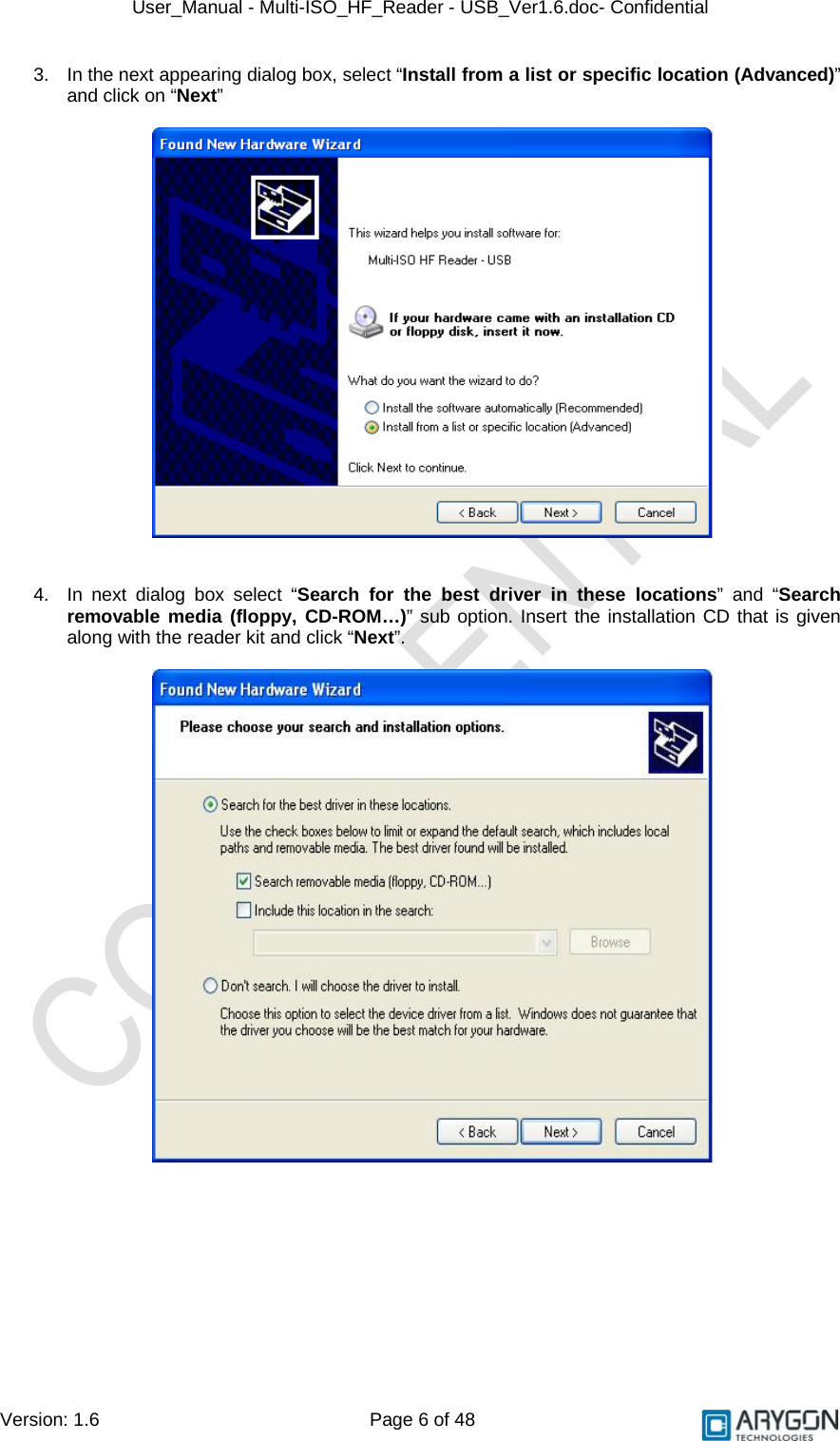
![User_Manual - Multi-ISO_HF_Reader - USB_Ver1.6.doc- Confidential Version: 1.6 Page 17 of 48 4.2 ATR Generation To make contactless cards available within the PCSC framework, the Multi-ISO HF USB Reader/Writer generates a PCSC compliant ATR according to PCSC v2.01.09 “Interoperability Specification for ICCs and Personal Computer Systems” (reference [R2]) 4.2.1 CPU Cards The ATR of Contactless processor cards are composed as described in PCSC v2.01.09, Part3: Requirements for PC connected Interface Devices, 3.1.3.2.3.1, Table 3.5 4.2.2 Storage Cards The ATR of storage cards (i.e. cards without CPU) are composed as described in PCSC v2.01.09, Part3: Requirements for PC connected Interface Devices, 3.1.3.2.3.2, Table 3.6. In order to allow the HOST application to identify a storage card type properly, its standard and card name is mapped according to the Part3: Supplement Document of PCSC v2.01.04 Note: The registered Application Provider Identifier (RID) returned by the Multi-ISO HF USB Reader/Writer for storage cards (cards without CPU) is A0 00 00 03 06, which is the RID of the PCSC workgroup](https://usermanual.wiki/IDENTIVE-TECHNOLOGIES/AMID2US00/User-Guide-1147722-Page-17.png)
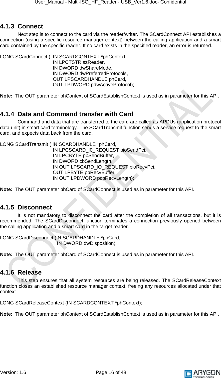
![User_Manual - Multi-ISO_HF_Reader - USB_Ver1.6.doc- Confidential Version: 1.6 Page 18 of 48 5 Accessing Reader through PCSC In some specific situations, PC/SC specifications are not enough to cover the whole functional field. This happens typically • When working with memory cards or even microprocessor based cards not following the ISO 7816-4 standard (APDU formalism) • When needing to perform actions on to the reader/writer itself, and not onto the card (Like modifying the RF parameters of the reader/writer) In order to cover the above two cases, proprietary 7816 wrappers are supported. These are called Pseudo APDUs. Refer to [R7] in order to understand the basic structure of APDU Reader commands are covered under this section. While Pseudo APDU for accessing ISO 7816-4 non-compliant cards are covered in Section 6 Mifare cards and ISO 15693 cards use proprietary 7816 APDU structures. DESFire cards use the 7816 wrapper as described in the DESFire specifications [R3] & [R11] All command and response bytes are sent and received as hexadecimal values respectively Note: In the pseudo APDUs described in this section, specifying a value of 00 in the Le field indicates maximum no of available response bytes from the card, as described in reference [R7] 5.1 Reader Control Commands The Reader/Writer control commands are used to modify the reader/writer parameters in order to fine tune the reader/writer’s performance or to suit the end applications requirements. It follows standard ISO 7816-4 (as per reference [R7]) command/ response format The Reader/Writer control commands have the following general APDU format Command Format: CLA INS P1 P2 Lc Data Le FF 00 00 00 No of bytes in Data field Reader/Writer Control Command Command Parameters 00 Response Format: Data Status Word Reader/Writer Control Response SW1 SW2 For possible values and description of status word refer Table 6.1 The following are the Reader/Writer control commands: 5.1.1 Get Static RF Parameters Get Static RF Parameters command is used to get the RF parameters from the non-volatile area of the reader/writer Command Data: CLA INS P1 P2 Lc Data Le FF 00 00 00 03 01 00 03 00 Response Data: Data Status RF Parameters as in the Structure shown in Table 4.1 (128 bytes) 9000](https://usermanual.wiki/IDENTIVE-TECHNOLOGIES/AMID2US00/User-Guide-1147722-Page-18.png)
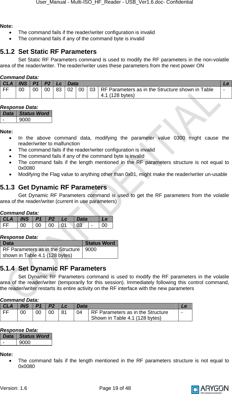
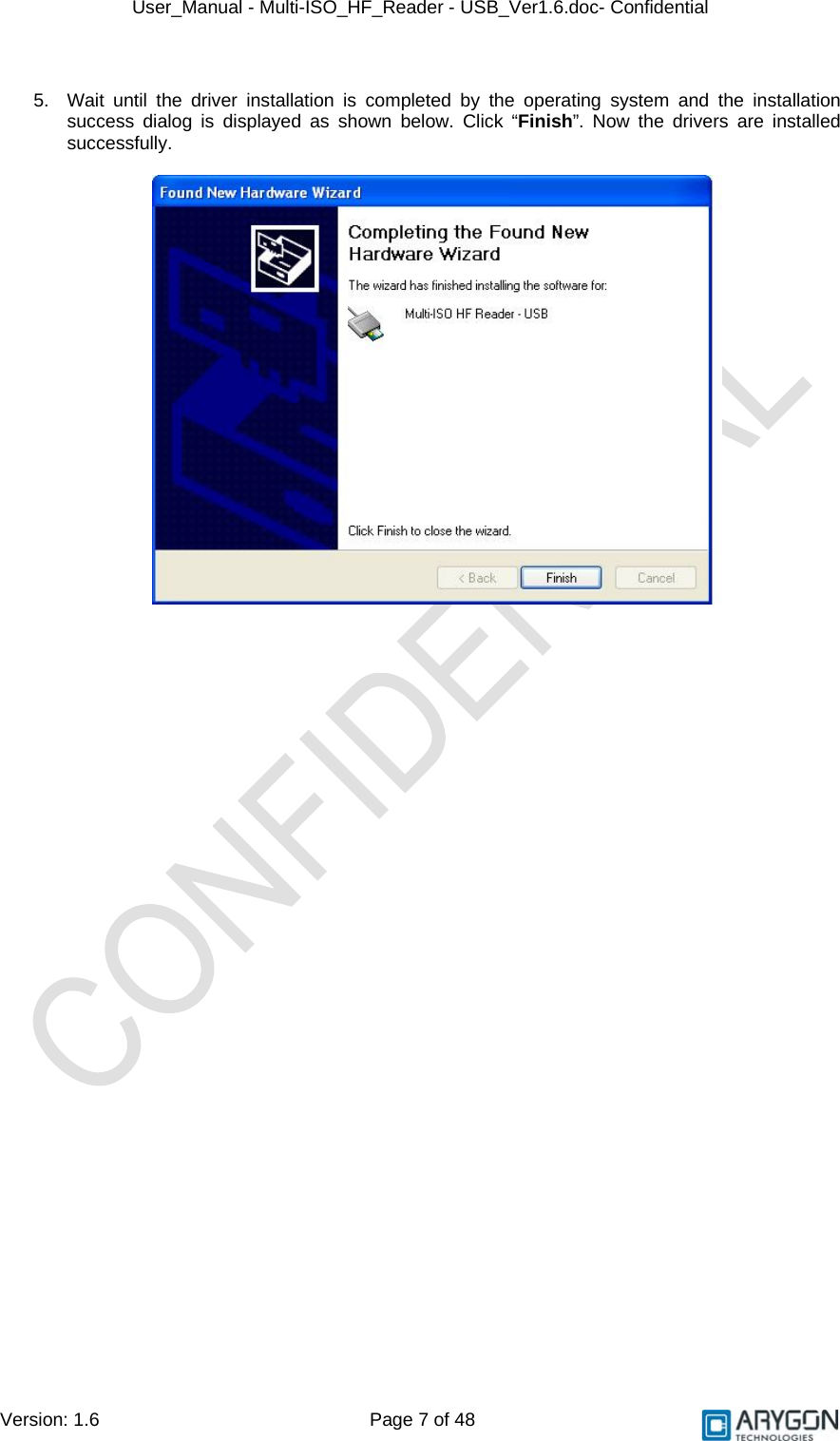
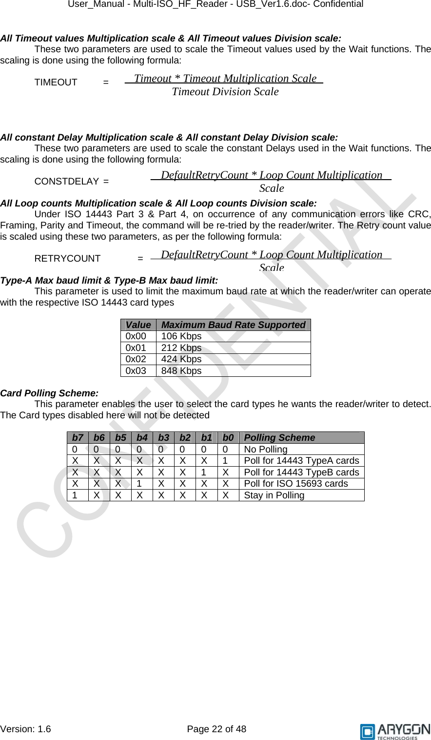
![User_Manual - Multi-ISO_HF_Reader - USB_Ver1.6.doc- Confidential Version: 1.6 Page 20 of 48 • The command fails if any of the command byte is invalid 5.1.5 RF Parameters Data Structure Parameter No of bytes Offset Length in bytes 2 [Value = 0x0080] 0 Flag 1 [Value = 0x01] 2 A106 - CWCONDUCTANCE 1 3 A106 – RXTHRESHOLD 1 4 A106 - RXCONTROL1 1 5 A212 - CWCONDUCTANCE 1 6 A212 - RXTHRESHOLD 1 7 A212 - RXCONTROL1 1 8 A424 - CWCONDUCTANCE 1 9 A424 - RXTHRESHOLD 1 10 A424 - RXCONTROL1 1 11 A828 - CWCONDUCTANCE 1 12 A828 - RXTHRESHOLD 1 13 A828 - RXCONTROL1 1 14 B106 - CWCONDUCTANCE 1 15 B106 - RXTHRESHOLD 1 16 B106 - RXCONTROL1 1 17 B106 - MODCONDUCTANCE 1 18 B106 - TYPEBFRAMING 1 19 B212 - CWCONDUCTANCE 1 20 B212 - RXTHRESHOLD 1 21 B212 - RXCONTROL1 1 22 B212 - MODCONDUCTANCE 1 23 B212 - TYPEBFRAMING 1 24 B424 - CWCONDUCTANCE 1 25 B424 - RXTHRESHOLD 1 26 B424 - RXCONTROL1 1 27 B424 - MODCONDUCTANCE 1 28 B424 - TYPEBFRAMING 1 29 B848 - CWCONDUCTANCE 1 30 B848 - RXTHRESHOLD 1 31 B848 - RXCONTROL1 1 32 B848 - MODCONDUCTANCE 1 33 B848 - TYPEBFRAMING 1 34 TESTANASELECT 1 35 TESTDIGISELECT 1 36 Reserved 11 37 RF Reset Width in milliseconds 2 48 Card de-bounce delay in milliseconds 2 50 All Timeout Values Multiplication scale 1 52 All Timeout Values Division scale 1 53 All constant Delay Multiplication scale 1 54 All constant Delay Division scale 1 55 All Loop counts Multiplication scale 1 56 All Loop counts Division scale 1 57 Type-A Max baud limit 1 58 Type-B Max baud limit 1 59 Card Polling scheme 1 60 Reserved 67 61 Table 4.1 RF parameters data structure](https://usermanual.wiki/IDENTIVE-TECHNOLOGIES/AMID2US00/User-Guide-1147722-Page-20.png)
![User_Manual - Multi-ISO_HF_Reader - USB_Ver1.6.doc- Confidential Version: 1.6 Page 21 of 48 Naming Convention In the above table, • The Parameters starting with ‘A’ or ‘B’ refer to the respective ISO 14443 card types • The number following the alphabet indicates the baud rate at which the card should be operating • The actual RF parameter follows the ‘-’. This parameter will take effect for that type of card operating at that baud rate Example: - A106 – CWCONDUCTANCE indicates the CWCONDUCTANCE parameter of ISO 14443 TypeA cards operating at 106 Kbps Parameter Description RF Control Parameter: “CWCONDUCTANCE” parameter controls the strength of RF field when there is no modulation. Its value can vary from 0x00 to 0x3F. The chosen value would get directly programmed into the (Address 0x12) RFID reader silicon. For more details refer to the respective datasheet of RFID reader silicon (reference [R12]). “RXTHRESHOLD” parameter controls the receiver input threshold levels. The specified value would get directly programmed into the (Address 0x1C) RFID reader silicon. For more details refer to the respective datasheet of RFID reader silicon (reference [R12]). “RXCONTROL1” parameter controls the receiver input stage gain levels and the low pass filters. The specified value would get directly programmed into the (Address 0x19) RFID reader silicon. For more details refer to the respective datasheet of RFID reader silicon (reference [R12]). “MODCONDUCTANCE” parameter controls the strength of RF field when there is 10% modulation for Type-B data transmission. Its value can vary from 0x00 to 0x3F. The chosen value would get directly programmed into the (Address 0x13) RFID reader silicon. For more details refer to the respective datasheet of RFID reader silicon (reference [R12]). “TYPEBFRAMING” parameter controls the framing headers SOF & EOF of type B transmission frames. The specified value would get directly programmed into the (Address 0x17) RFID reader silicon. For more details refer to the respective datasheet of RFID reader silicon (reference [R12]). “TESTANASELECT” parameter controls the analog debug output pin AUX. The specified value would get directly programmed into the (Address 0x3A) RFID reader silicon. For more details refer to the respective datasheet of RFID reader silicon (reference [R12]). “TESTDIGISELECT” parameter controls the digital debug output pin MFOUT. The specified value would get directly programmed into the (Address 0x3D) RFID reader silicon. For more details refer to the respective datasheet of RFID reader silicon (reference [R12]). RF Reset Width in milliseconds: This parameter defines the width of RF Reset (no RF Power) during the polling sequence. The value entered is in decimal, from 0 to 65535. The RF reset would have a width of this much amount of time in milliseconds. Card de-bounce delay in milliseconds: This parameter defines the time in milliseconds for which the card arrival is polled and reconfirmed by repeated RNAK polling, before notifying the arrival of a new card into the RF field, to the host. The value entered is in decimal, from 0 to 65535.](https://usermanual.wiki/IDENTIVE-TECHNOLOGIES/AMID2US00/User-Guide-1147722-Page-21.png)
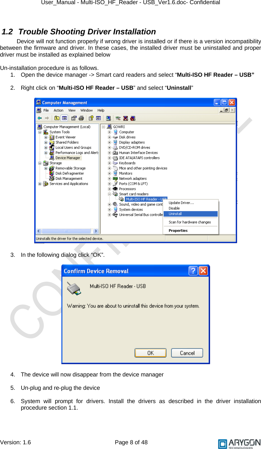
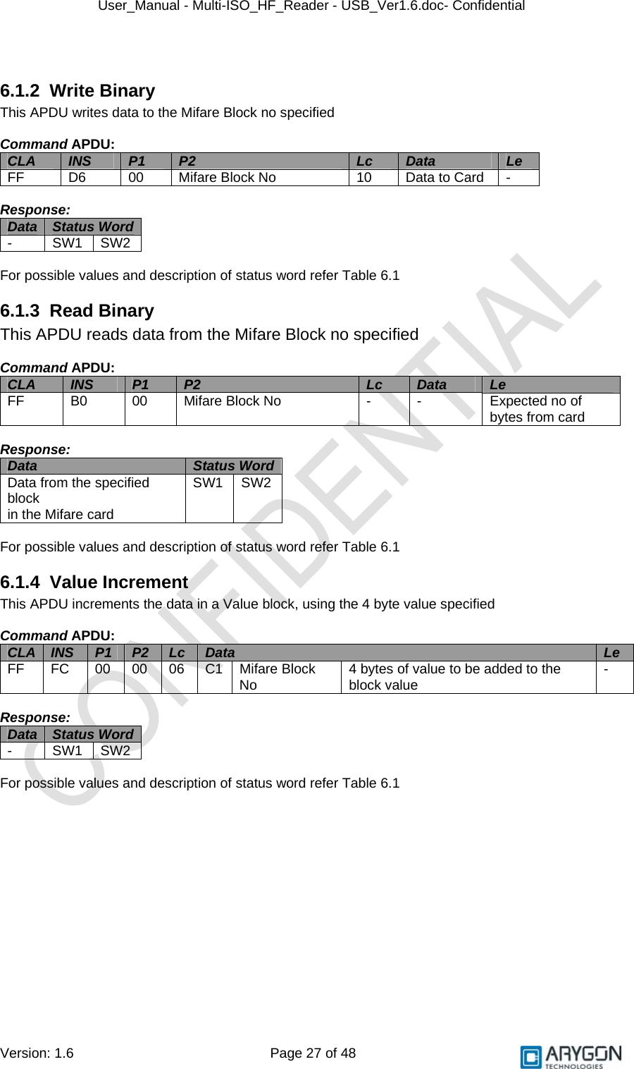
![User_Manual - Multi-ISO_HF_Reader - USB_Ver1.6.doc- Confidential Version: 1.6 Page 26 of 48 6 Accessing Cards through PCSC Mifare cards and ISO 15693 cards use proprietary 7816 APDU structures. DESFire cards use the 7816 wrapper as described in the DESFire specifications [R3] & [R11] All command and response bytes are sent and received as hexadecimal values respectively Note: In the pseudo APDUs described in this section, specifying a value of 00 in the Le field indicates maximum no of available response bytes from the card, as described in reference [R7] 6.1 Mifare Cards Pseudo APDUs supported for Mifare cards are explained in this section 6.1.1 Authenticate This APDU performs three pass authentication with the card for the Block No. specified in the data field. It uses the Key of the Key no specified Command APDU: CLA INS P1 P2 Lc Data Le FF 86 00 00 05 See Table below (5 bytes) - Data: Byte 1 Byte 2 Byte 3 Byte 4 Byte 5 01 Block No (MSB) Block No (LSB) 00 Key No. Where, Block No - Block number of the Mifare card which is to be authenticated Key No - Key number specified in the RDRLoadKeys command to store the corresponding Authentication key in the non-volatile area of the reader/writer Response: Data Status Word - SW1 SW2 For possible values and description of status word refer Table 6.1](https://usermanual.wiki/IDENTIVE-TECHNOLOGIES/AMID2US00/User-Guide-1147722-Page-26.png)
![User_Manual - Multi-ISO_HF_Reader - USB_Ver1.6.doc- Confidential Version: 1.6 Page 29 of 48 6.2 ISO 15693 Cards Pseudo APDUs supported for ISO 15693 cards are explained in this section 6.2.1 Read Single Block This APDU reads 4 bytes of data from the block no specified Command APDU: CLA INS P1 P2 Lc Data Le FF FC 00 00 No of bytes in Data field Read single block command as described in reference [R1] Expected no of bytes from card Response: Data Status Word Read single block response as described in reference [R1] SW1 SW2 For possible values and description of status word refer Table 6.1 6.2.2 Write Single Block This APDU writes 4 bytes of data to the block no specified Command APDU: CLA INS P1 P2 Lc Data Le FF FC 00 00 No of bytes in Data field Write single block command as described in reference [R1] - Response: Data Status Word Write single block response as described in reference [R1] SW1 SW2 For possible values and description of status word refer Table 6.1 6.2.3 Lock Block This APDU Locks the specified Block no. Once successfully locked, the block will become read only Command APDU: CLA INS P1 P2 Lc Data Le FF FC 00 00 No of bytes in Data field Lock block command as described in reference [R1] - Response: Data Status Word Lock block response as described in reference [R1] SW1 SW2 For possible values and description of status word refer Table 6.1](https://usermanual.wiki/IDENTIVE-TECHNOLOGIES/AMID2US00/User-Guide-1147722-Page-29.png)
![User_Manual - Multi-ISO_HF_Reader - USB_Ver1.6.doc- Confidential Version: 1.6 Page 30 of 48 6.2.4 Read Multiple Blocks This APDU reads 4 bytes of data from each of the requested no of blocks, starting from the block no specified Command APDU: CLA INS P1 P2 Lc Data Le FF FC 00 00 No of bytes in Data field Read multiple block command as described in reference [R1] Expected no of bytes from card Response: Data Status Word Read multiple block response as described in reference [R1] SW1 SW2 For possible values and description of status word refer Table 6.1](https://usermanual.wiki/IDENTIVE-TECHNOLOGIES/AMID2US00/User-Guide-1147722-Page-30.png)
![User_Manual - Multi-ISO_HF_Reader - USB_Ver1.6.doc- Confidential Version: 1.6 Page 31 of 48 6.2.5 Write AFI This APDU writes the AFI value specified into the card’s memory Command APDU: CLA INS P1 P2 Lc Data Le FF FC 00 00 No of bytes in Data field Write AFI command as described in reference [R1] - Response: Data Status Word Write AFI response as described in reference [R1] SW1 SW2 For possible values and description of status word refer Table 6.1 6.2.6 Write DSFID This APDU writes the DSFID value specified into the card’s memory Command APDU: CLA INS P1 P2 Lc Data Le FF FC 00 00 No of bytes in Data field Write DSFID command as described in reference [R1] - Response: Data Status Word Write DSFID response as described in reference [R1] SW1 SW2 For possible values and description of status word refer Table 6.1 6.2.7 Get System Information: This APDU retrieves system information, like UID, DSFID, AFI, Memory information, IC Manufacturer code etc from the card Command APDU: CLA INS P1 P2 Lc Data Le FF FC 00 00 No of bytes in Data field Get system information command as described in reference [R1] Expected no of bytes from card Response: Data Status Word Get system information response as described in reference [R1] SW1 SW2 For possible values and description of status word refer Table 6.1](https://usermanual.wiki/IDENTIVE-TECHNOLOGIES/AMID2US00/User-Guide-1147722-Page-31.png)
![User_Manual - Multi-ISO_HF_Reader - USB_Ver1.6.doc- Confidential Version: 1.6 Page 32 of 48 6.2.8 Get Multiple Block Security Status: This APDU retrieves the block security status of each of the requested no of blocks, starting from the block no specified Command APDU: CLA INS P1 P2 Lc Data LeFF FC 00 00 No of bytes in Data field Get multiple block security status command as described in reference [R1] 00 Response: Data Status Word Get multiple block security status response as described in reference [R1] SW1 SW2 For possible values and description of status word refer Table 6.1 Note: In all the above 15693 card commands, the optional Flags byte and optional UID field must be omitted. In all the above 15693 card responses, Flags byte will be omitted and Error Code (if any) will be sent as SW2](https://usermanual.wiki/IDENTIVE-TECHNOLOGIES/AMID2US00/User-Guide-1147722-Page-32.png)
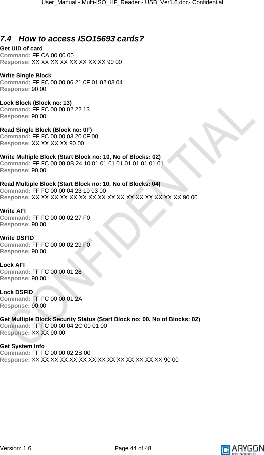
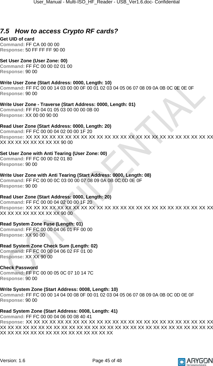
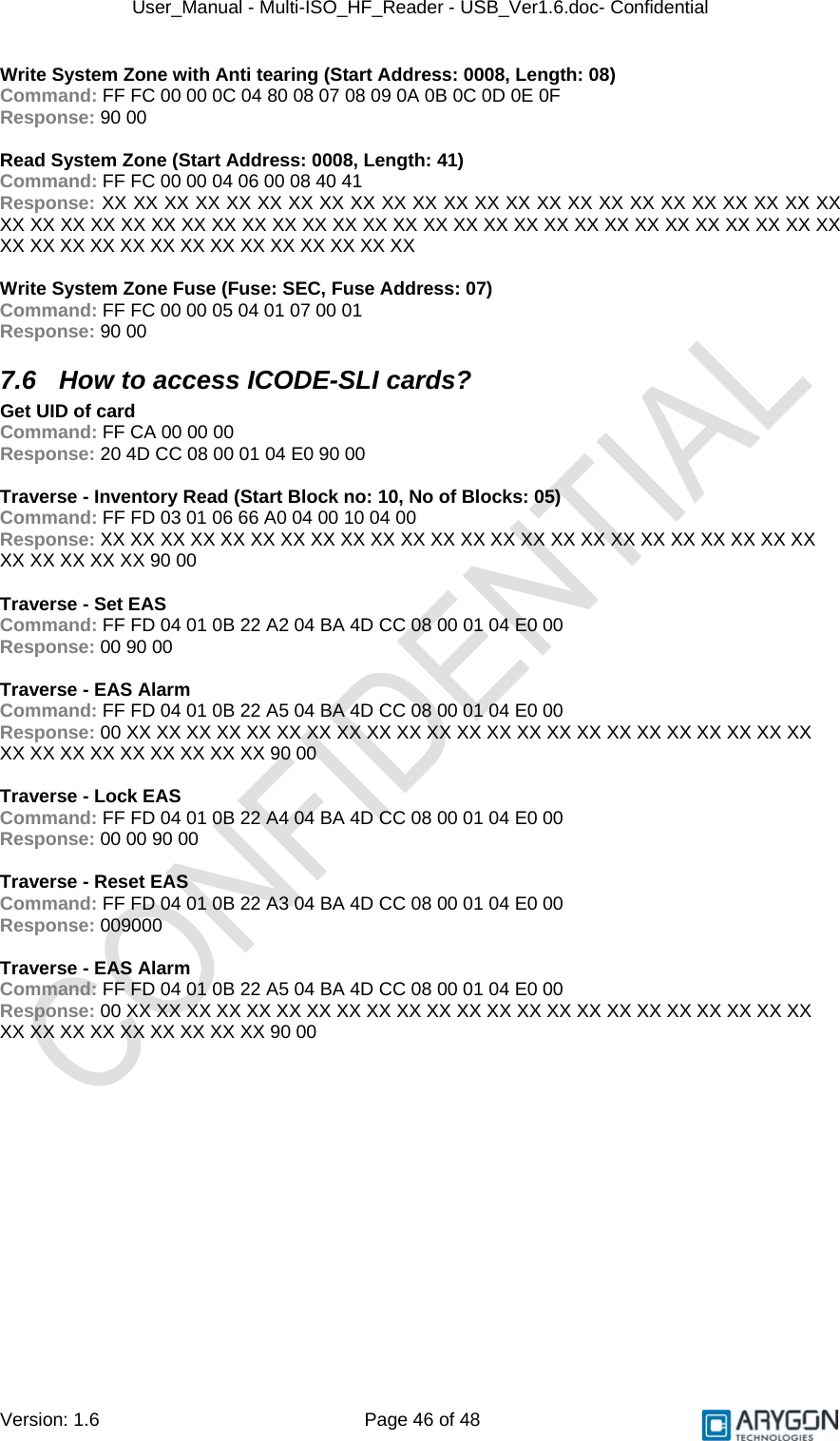
![User_Manual - Multi-ISO_HF_Reader - USB_Ver1.6.doc- Confidential Version: 1.6 Page 33 of 48 6.3 Crypto RF Cards Pseudo APDUs supported for Atmel CryptoRF cards are explained in this section 6.3.1 Set User Zone This APDU selects the specified user Zone. All further user zone operations will be done in the selected user zone. The command is also used to enable anti-tearing mode, following which all writes to this user zone will use anti-tearing Command APDU: CLA INS P1 P2 Lc Data Le FF FC 00 00 No of bytes in Data field Set User Zone Command as per reference [R10] - Response: Data Status Word Set User Zone response as per reference [R10] SW1 SW2 For possible values and description of status word refer Table 6.1 6.3.2 Read User Zone This APDU reads data from the currently selected user zone Command APDU: CLA INS P1 P2 Lc Data Le FF FC 00 00 No of bytes in Data field Read User Zone Command as per reference [R10] Expected no of bytes from card Response: Data Status Word Read User Zone response as per reference [R10] SW1 SW2 For possible values and description of status word refer Table 6.1 6.3.3 Write User Zone This APDU writes data to the currently selected user zone. In anti-tearing mode the maximum no of bytes that can be written is 8 bytes Command APDU: CLA INS P1 P2 Lc Data Le FF FC 00 00 No of bytes in Data field Write User Zone Command as per reference [R10] - Response: Data Status Word Write User Zone response as per reference [R10] SW1 SW2 For possible values and description of status word refer Table 6.1](https://usermanual.wiki/IDENTIVE-TECHNOLOGIES/AMID2US00/User-Guide-1147722-Page-33.png)
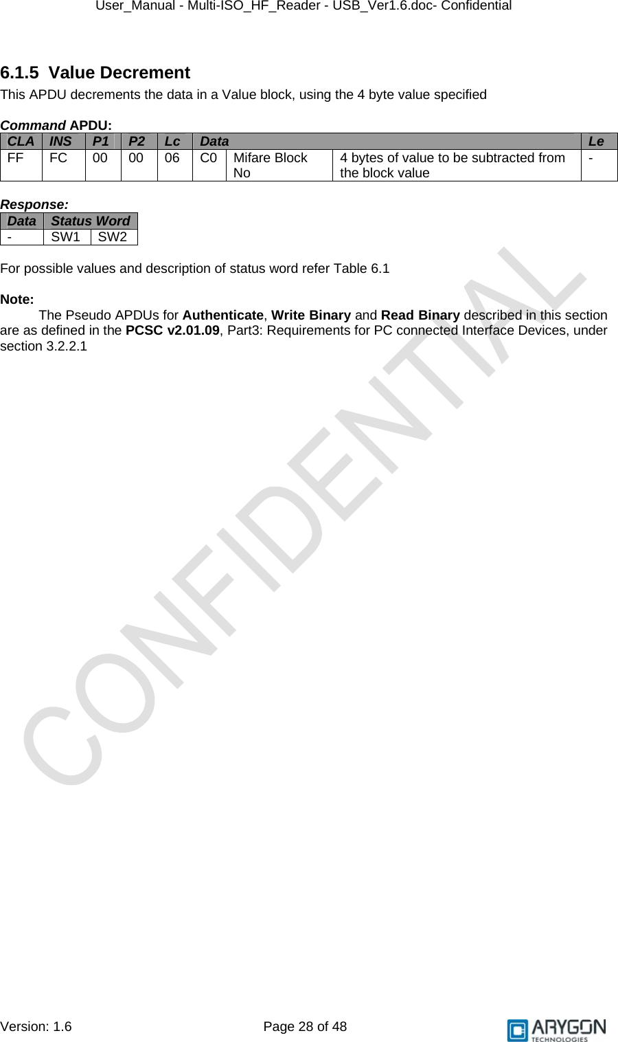
![User_Manual - Multi-ISO_HF_Reader - USB_Ver1.6.doc- Confidential Version: 1.6 Page 34 of 48 6.3.4 Read System Zone This APDU reads system data from the configuration memory of the card. Depending on the value of the PARAM byte (part of the command), this command may read data from the configuration zone, the fuses or a checksum Command APDU: CLA INS P1 P2 Lc Data Le FF FC 00 00 No of bytes in Data field Read System Zone Command as per reference [R10] Expected no of bytes from card Response: Data Status Word Read System Zone response as per reference [R10] SW1 SW2 For possible values and description of status word refer Table 6.1 6.3.5 Write System Zone This APDU writes data to the configuration memory. Depending on the value of the PARAM byte (part of the command), this command may write data to the configuration zone or program fuses. The anti-tearing mode can also be enabled using the PARAM byte. The maximum number of bytes that can be written in anti-tearing mode is 8 bytes Command APDU: CLA INS P1 P2 Lc Data Le FF FC 00 00 No of bytes in Data field Write System Zone Command as per reference [R10] - Response: Data Status Word Write System Zone response as per reference [R10] SW1 SW2 For possible values and description of status word refer Table 6.1 6.3.6 Check Password This APDU is used to send the password for validation against the password selected with the password index byte (part of the command). This command is used to gain access, to read or write in user zones that require password validation Command APDU: CLA INS P1 P2 Lc Data Le FF FC 00 00 No of bytes in Data field Check Password Command as per reference [R10] - Response: Data Status Word Check Password response as per reference [R10] SW1 SW2 For possible values and description of status word refer Table 6.1 Note: In all the above CryptoRF card commands, the CID field (higher nibble of the command byte), must be set to 0. In all the above CryptoRF card responses, the Command byte and ACK/NACK byte will be omitted. Status byte will be sent as SW2](https://usermanual.wiki/IDENTIVE-TECHNOLOGIES/AMID2US00/User-Guide-1147722-Page-34.png)
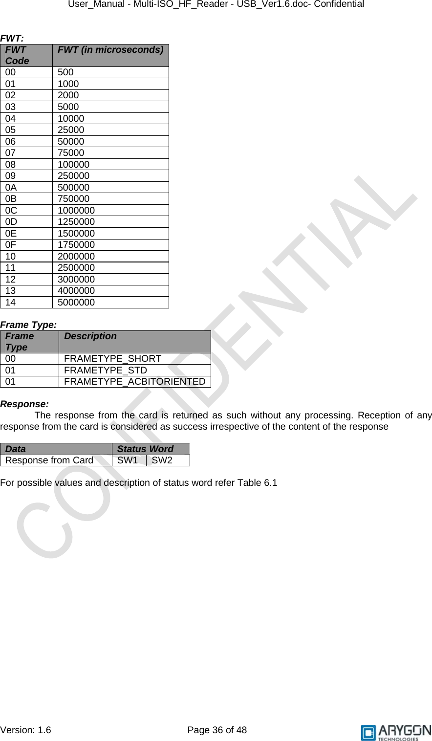
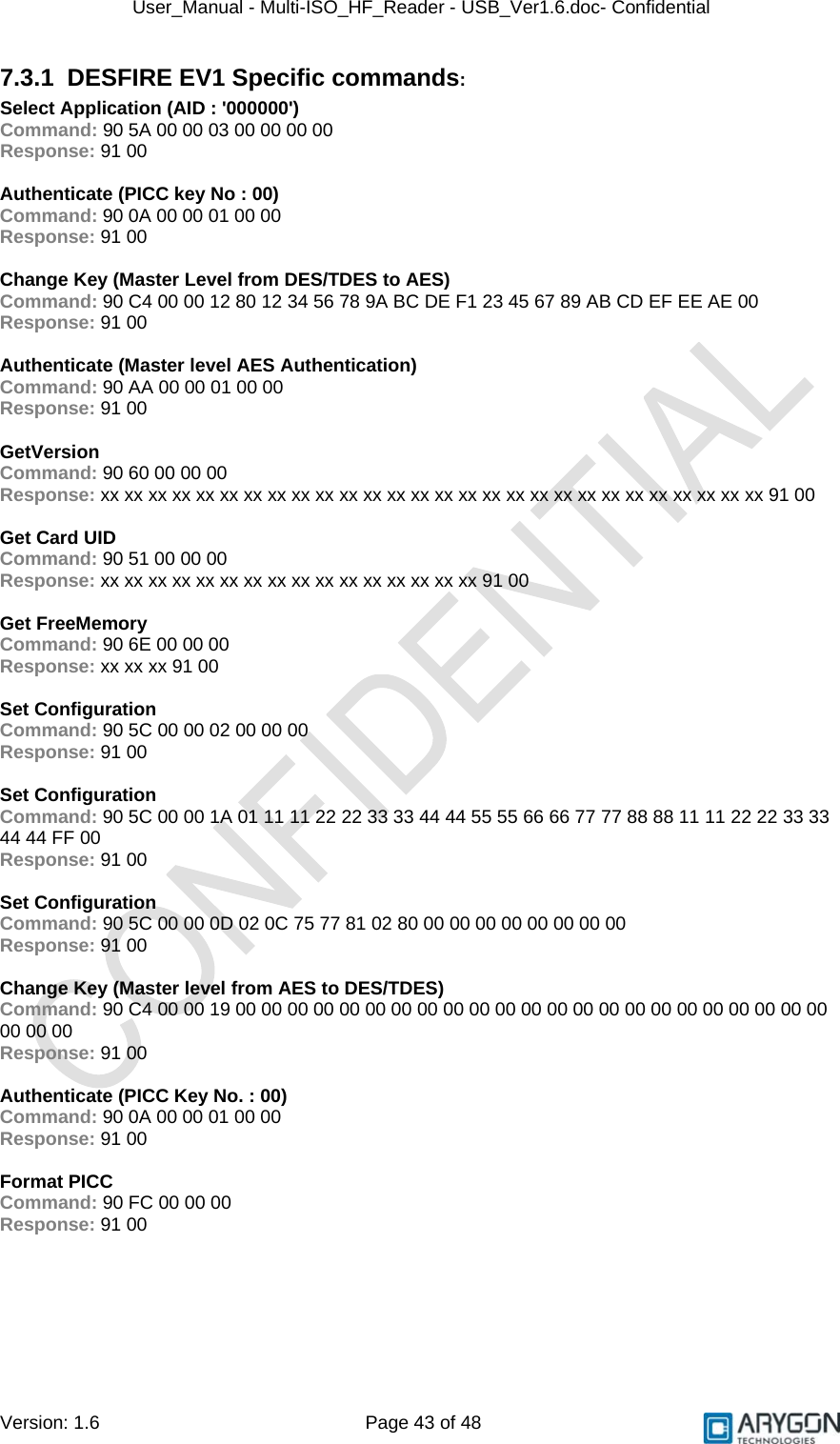
![User_Manual - Multi-ISO_HF_Reader - USB_Ver1.6.doc- Confidential Version: 1.6 Page 35 of 48 6.4 DESFire Cards For DESFire cards, the Multi-ISO HF USB Reader/Writer supports the 7816-4 APDU wrapper as described in the DESFire specification (as per reference [R3]). 6.5 Generic APDUs This section describes the generic Pseudo APDUs used with all supported cards 6.5.1 Get UID This APDU retrieves the card Unique ID (UID). Length of the UID varies depending on the card Command APDU: CLA INS P1 P2 Lc Data Le FF CA 00 00 - - 00 Response: Data Status Word UID of the Card SW1 SW2 For possible values and description of status word refer Table 6.1 6.5.2 Traverse This APDU is used to send the “Raw Card Command“ in the data field to the card without any command specific processing by the reader/writer and returns the response data from the Card. The reader/writer only takes care of the protocol specific processing (CRC, Prologue field etc ...) The reader/writer uses the Frame type specified in the P2 parameter field and the Frame waiting time specified in the P1 parameter field, while sending the command and receiving the response, respectively Command APDU: CLA INS P1 P2 Lc Data Le FF FD FWT Code (as defined in the table below) Frame Type (as defined in the table below) No of data bytes sent to the card Raw Card Command 00](https://usermanual.wiki/IDENTIVE-TECHNOLOGIES/AMID2US00/User-Guide-1147722-Page-35.png)
![User_Manual - Multi-ISO_HF_Reader - USB_Ver1.6.doc- Confidential Version: 1.6 Page 48 of 48 Appendix B References [R1] ISO/IEC 15693 Part 3, Identification cards – Contactless integrated circuit(s) cards – Vicinity card(s) [R2] Interoperability Specification for ICCs and Personal Computer Systems Part 3 [R3] NXP Mifare® DESFire Datasheet (M075031.pdf) [R4] Microsoft’s PCSC reference documentation is included in most Visual Studio help system and available online at http://msdn.microsoft.com. Enter “WinSCard” or “SCardTransmit” keywords in the search box. [R5] PCSC workgroup: http://www.pcscworkgroup.com [R6] ISO/IEC 7816-3 Third Edition 2006-11-01 [R7] ISO/IEC 7816-4 Second Edition 2005-01-15 [R8] ISO/IEC 14443-4 First Edition 2001-02-01 [R9] ISO/IEC 14443-4 Amendment-1 2006-03-15 [R10] Atmel CryptoRF Specification (AT88SCXXXXCRF) Rev 2.0 2007-04-13 [R11] NXP Mifare® DESFire EV1 Functional Specification (MF3ICD81) [R12] Philips CL RC632 Multiple Protocol Contactless Reader IC Datasheet Rev 3.0 May 2003](https://usermanual.wiki/IDENTIVE-TECHNOLOGIES/AMID2US00/User-Guide-1147722-Page-48.png)