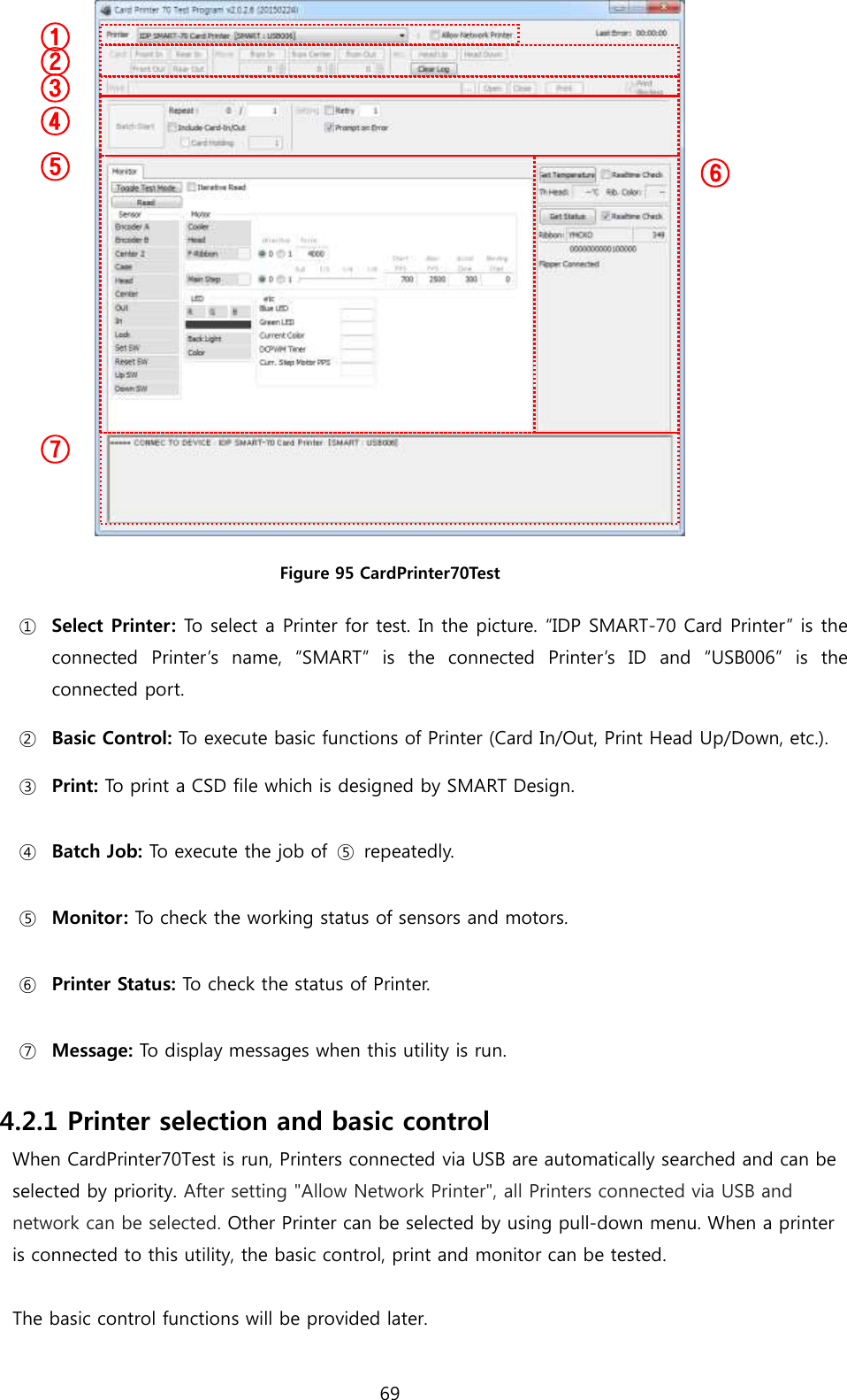
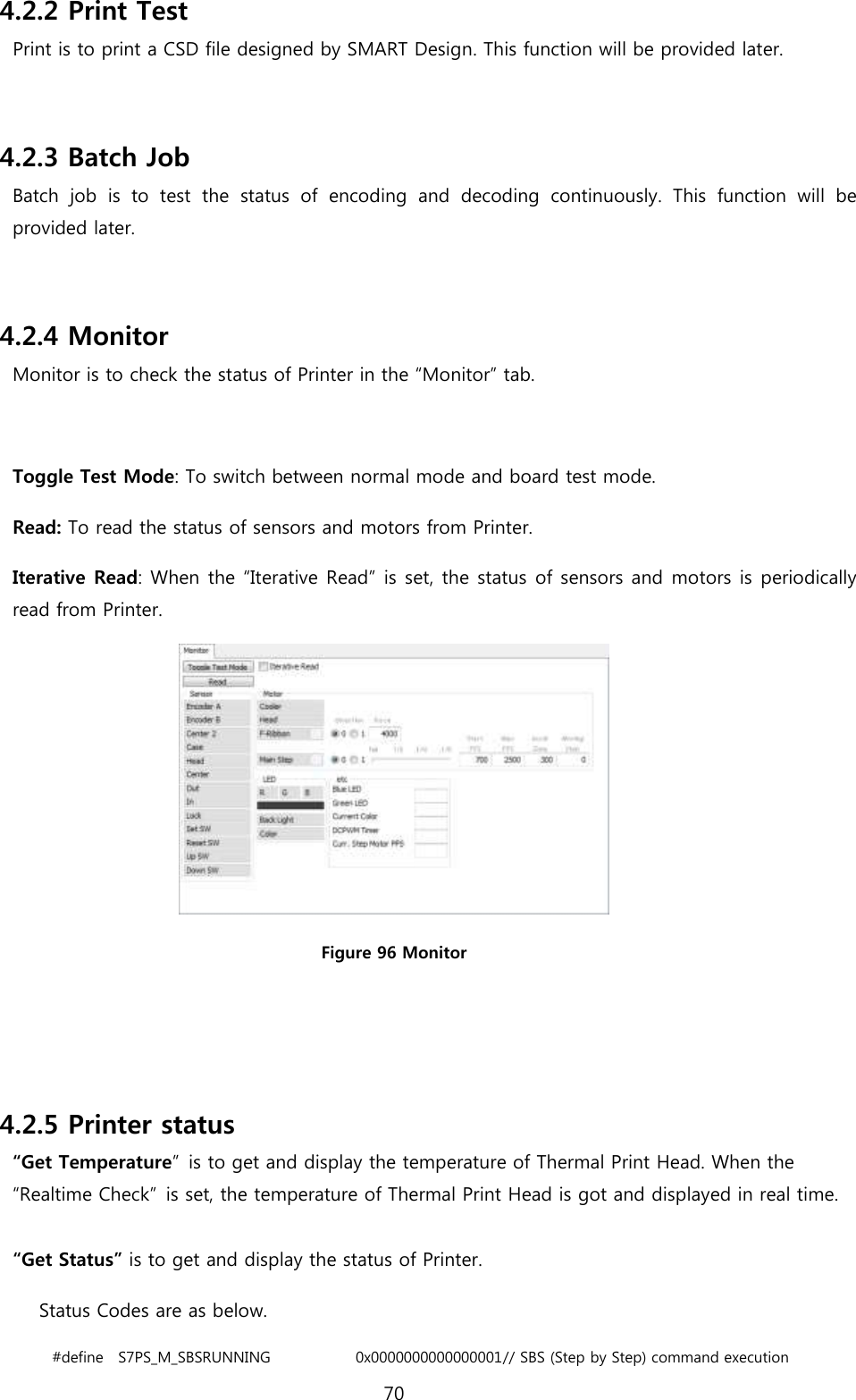
IDP SMART-70P Card Printer User Manual
IDP Corp., Ltd. Card Printer
UserManual.wiki
>
IDP
>
SMART 70P User Manual
User Manual
Navigation menu
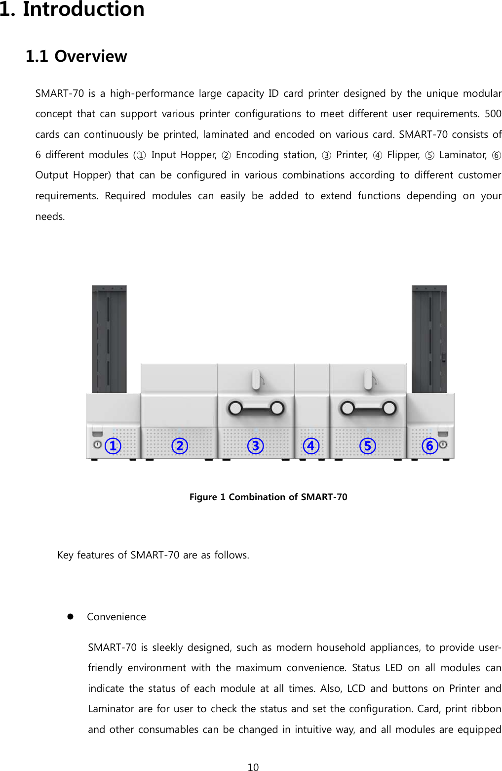
Upload a User Manual
Namespaces
Wiki Guide
HTML
PDF
Info
Views
User Manual
Discussion / Help
Navigation
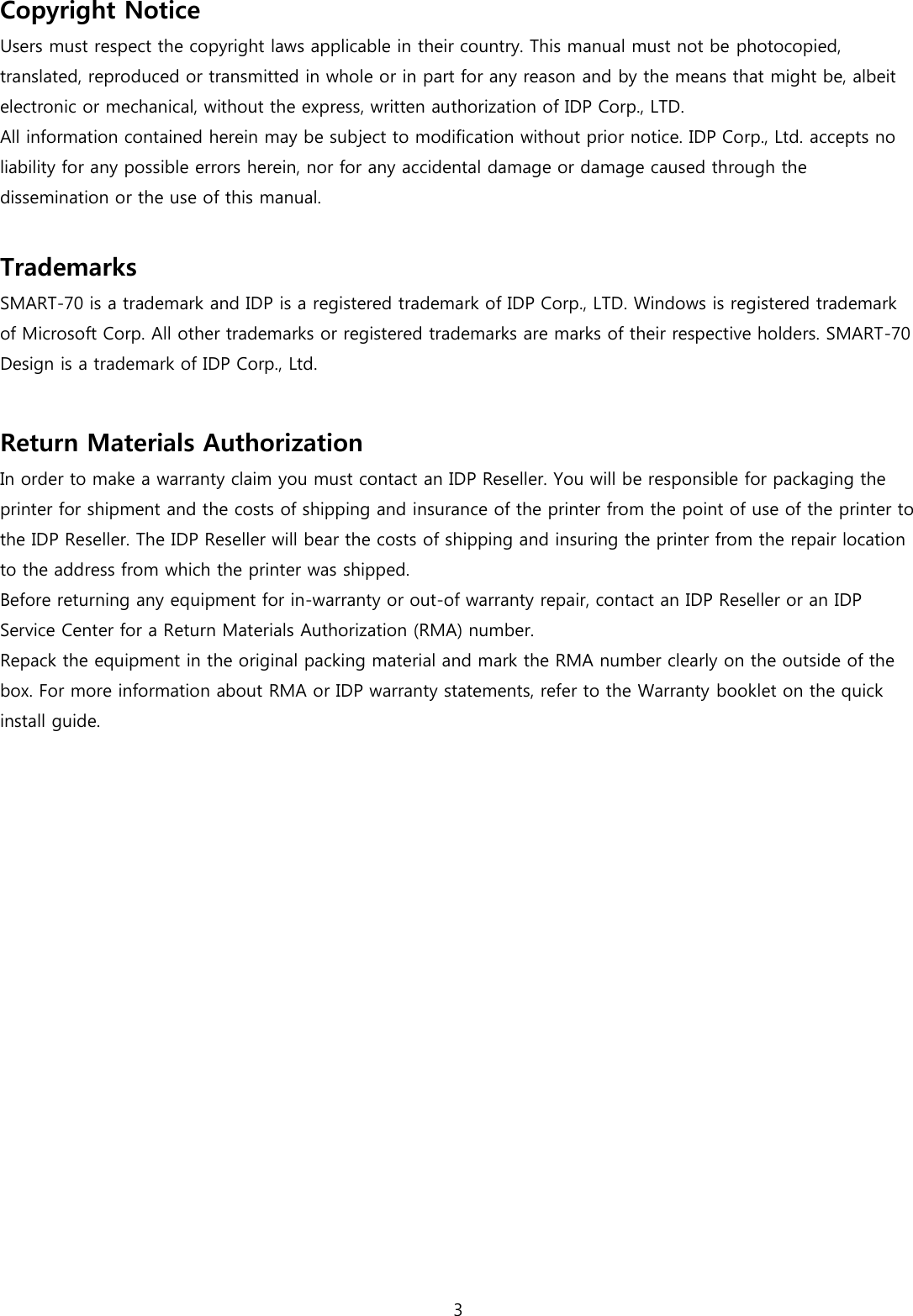
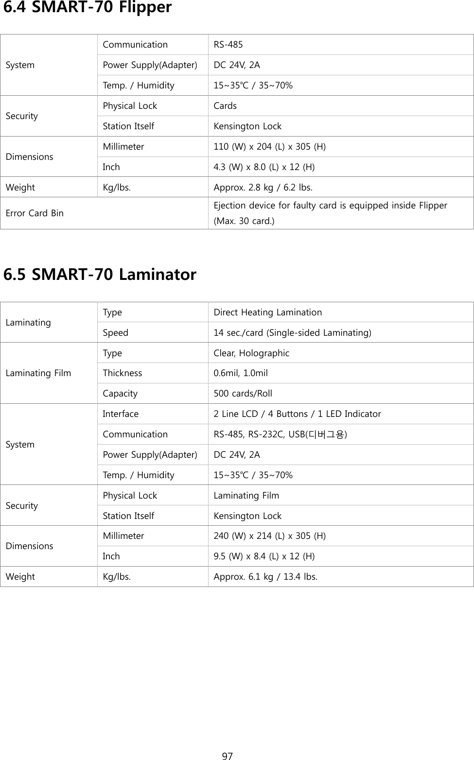
![40 2.1.10 Module combination setting Since SMART-70 is operated by the combination of multiple modules, the configuration for multiple modules combination must be set during the first installation of the modules. Printer module acts as master who is responsible to communicate with PC and control other modules, and if Printer module is not connected, Laminator module will act as master. The configuration for multiple modules combination can be set in the control panel of Printer module as below. SMART-70 Printer searches connected modules in booting, if the combination of connected modules is different with the configuration for multiple modules combination, Indicator LED is turned to yellow and the message for checking modules combination is displayed. Please follow below steps to set the configuration for multiple modules combinations for initial setting. A. The modules combination is IPFLO (Input Hopper + Printer + Flipper + Laminator + Output Hopper) but the configuration is different with the actually connected modules, so the configuration for multiple modules combination must be set again. Please press the [Select] button indicated by red arrow. Figure 43 Modules combination checking B. Existing modules combination is shown. Please press the [Select] button indicated by red arrow to adjust the configuration for multiple modules combination. Figure 44 Existing modules combination](https://usermanual.wiki/IDP/SMART-70P/User-Guide-2871831-Page-40.png)
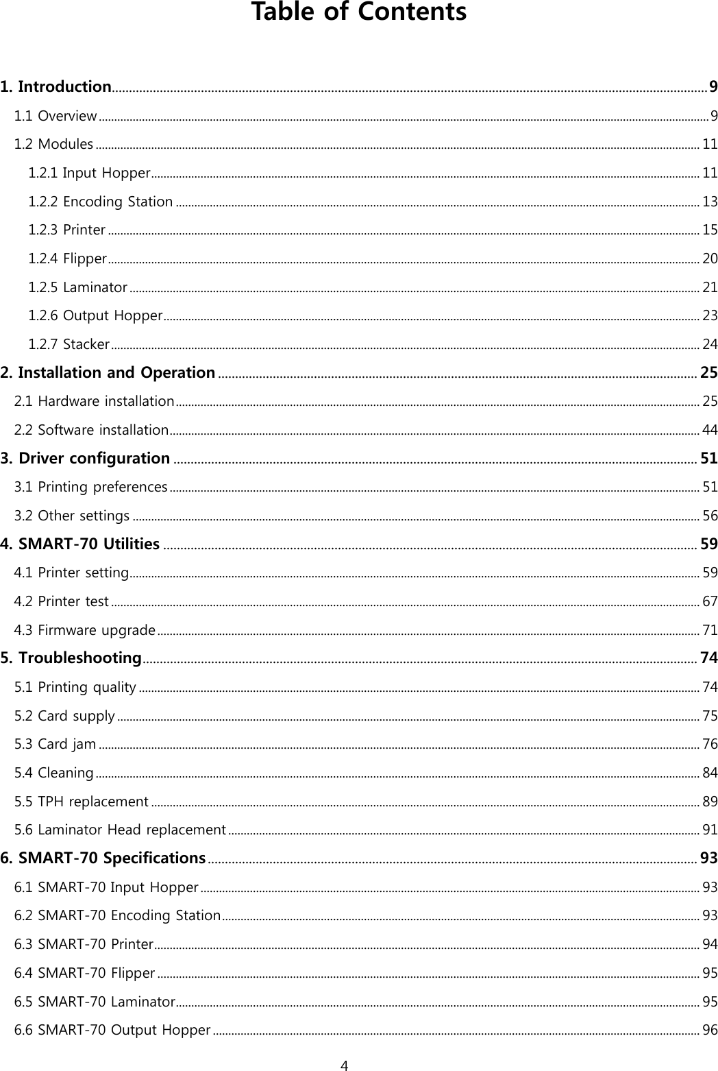
![41 C. The detected modules combination is shown. Please press the [Select] button indicated by red arrow to save the configuration for detected multiple modules combination. Figure 45 Adjusted modules combination D. The saved multiple modules combination is shown. Figure 46 Saved module combination E. Please wait a while until system is ready. Figure 47 Completed module combination](https://usermanual.wiki/IDP/SMART-70P/User-Guide-2871831-Page-41.png)
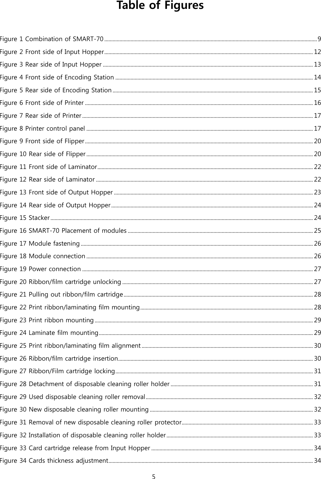
![43 B. On “System Config” menu, please press the [→] button indicated by red arrow. Figure 50 Printer menu (System Config) C. On “Network Config” menu, please press the [→] button indicated by red arrow. Figure 51 Printer menu (Network Config) D. On “Printer Config” menu, please press the [→] button indicated by red arrow. Figure 52 Printer menu (Printer Config)](https://usermanual.wiki/IDP/SMART-70P/User-Guide-2871831-Page-43.png)
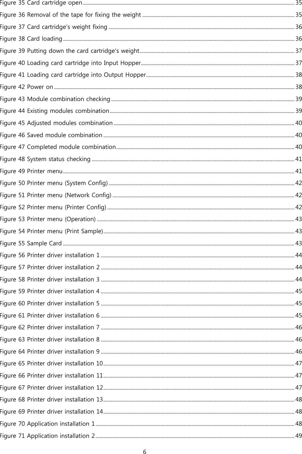
![44 E. On “Operation” menu, please press the [Select] button indicated by red arrow. Figure 53 Printer menu (Operation) F. On “Print Sample” menu, please press the [Select] button indicated by red arrow. Figure 54 Printer menu (Print Sample) G. Please wait a while until sample card is printed as figure. Figure 55 Sample Card](https://usermanual.wiki/IDP/SMART-70P/User-Guide-2871831-Page-44.png)
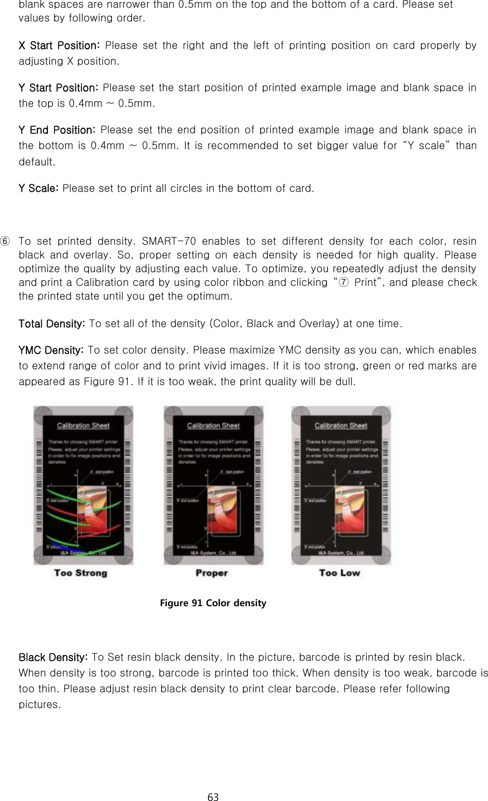
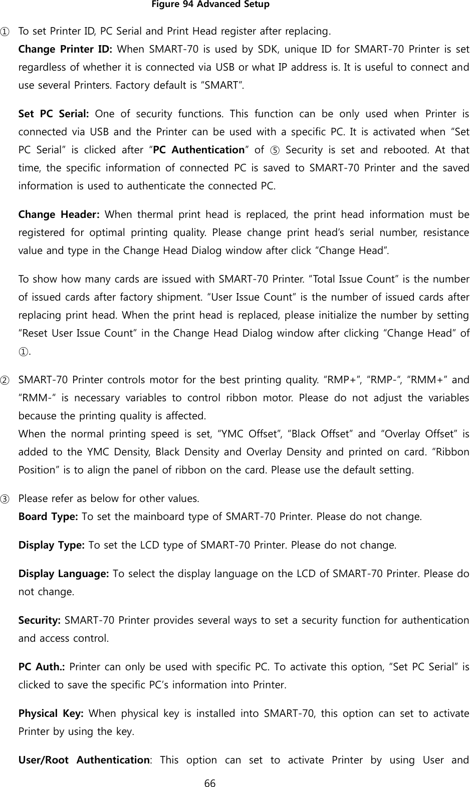
![53 3.1.3 Advanced setup For Advanced setup, please click the “Advanced” button on “Printing Preferences” window and you can adjust the advanced setting. Reset Default Values: Advanced setting is reset to the default values. Color Correction: Adjusting gamma value of each color panel can change color sense. The higher gamma value is the darker color. The absolute printing density can be adjusted by using “CardPrinter70Setup” utility. - Main [-100:100]: To adjust the gamma values of all panels. - Yellow [-100:100]: To adjust the gamma value of the yellow panel. - Magenta [-100:100]: To adjust the gamma value of the magenta panel. - Cyan [-100:100]: To adjust the gamma value of the cyan panel. - Black [-100:100]: To adjust the gamma value of the resin black panel. - Overlay [-100:100]: To adjust the gamma value of the overlay panel. Position Processing: The printing position between panels can be adjusted. If the value is higher, the positions are more accurate but the color sense may be a little lower. - Color [-32:32]: To adjust the printing position of the color panels (yellow, magenta and cyan). - Mono [-32:32]: To adjust the printing position of the resin black panel. - Overlay [-32:32]: To adjust the printing position of the overlay panel. Resin Black (K) Processing: The method to extract the data to be printed by the resin black is specified. - Text [0:100]: To set the density criteria for extracting the text to be printed by the resin black. - Dot [0:100]: To set density criteria for extracting the pixels to be printed by the resin black. - Threshold [0:100]: To set density criteria for printing by the resin black when the dithering is performed by using the Threshold. - Dithering Degree [0:100]: To set sharpness when the dithering is performed by using the Random. - Resin Extraction: Method to extract the data for the resin black. > Black object: Text, line, etc. Black objects are extracted. > Black Text: Text is only extracted.](https://usermanual.wiki/IDP/SMART-70P/User-Guide-2871831-Page-53.png)
![54 > Black Dots: All black dots are extracted. > Not Use: No extraction. Rewritable Controls: This property is only for rewritable printer. - Erase Density [0:100]: To set the temperature to erase the contents on rewritable card. Wait Option: This option can set the card’s waiting time at each encoding position when the smart card is encoded without using SDK. One contactless smart card encoder can be installed into SMART-70 Printer. One contactless and one contact smart card encoder can be installed into SMART-70 Encoding Station. When this option is set and the SDK is not used for encoding, the program which the smart card is recognized and encoded within the specified waiting time must be developed by yourself because the card is only waiting for a specified time at the encoding position. - Wait at Internal Module Contactless Encoding Position [On/Off]: To set that the contactless smart card is waiting at the contactless smart card encoding position in Printer. - Wait at External Module Contactless Encoding Position [On/Off]: To set that the contactless smart card is waiting at the contactless smart card encoding position in Encoding Station. - Wait at External Module Contact Encoding Position [On/Off]: To set that the contact smart card is waiting at the contact smart card encoding position in Encoding Station. > Card Side [Front/Back]: To set the direction of card when the card is waiting. > Wait Position [-100:100]: To adjust the card position from the previous waiting position of card to the left or the right (unit is 0.1mm). > Wait Time [0:1000]: To set the waiting time of card (unit is a second).](https://usermanual.wiki/IDP/SMART-70P/User-Guide-2871831-Page-54.png)
![73 Figure 97 CardPrinter70Firmware Devices: To select the Printer that firmware will be upgraded. Allow Network Printer: To set that Printers connected via network are displayed in Devices. Printer [ 0 ] / … : To select the modules of SMART-70 system that firmware is upgraded. Version: To displays the current firmware version of selected Printer. Binary File: To select the new firmware file. Please click “Browse” button to search and select the new firmware file. Manual Update: To upgrade the firmware manually. Update: To upgrade the firmware automatically. Update for automatic upgrading is generally recommended. Close: To close this utility. Message: Necessary information is displayed when the firmware is being upgraded. 4.3.1 Printer connection After SMART-70 Printer is connected to PC and the connected Printer is selected on Devices of CardPrinter70Firmware, all modules of SMART-70 System are displayed as tabs. SMART-70 System is combined by "Printer module 0" and "Flipper module 0" as Figure.](https://usermanual.wiki/IDP/SMART-70P/User-Guide-2871831-Page-73.png)
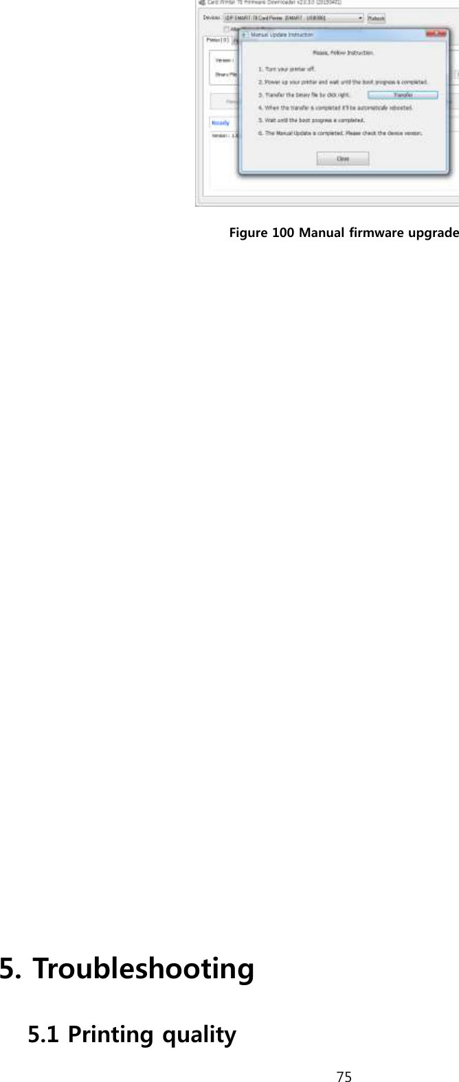
![74 Figure 98 Modules of SMART-70 System (Printer, Flipper) 4.3.2 Module Firmware Upgrade After clicking the tab of the combined modules of SMART-70 System such as “Printer [ 0 ]” or Flipper [ 0 ]”, please click “Browse” and search and select the new firmware for the module. After selecting the new firmware, “Manual Update” and “Update” is activated. Please click “Update” for automatic firmware upgrade, and the Printer is automatically rebooted after firmware upgrade. (Caution. Please do not do another job until the firmware upgrade is successfully completed and do not turn off the Printer.) Figure 99 Ready for firmware upgrade In case there is some problems in automatic firmware upgrade, please click “Manual Update” to manually upgrade firmware. According to the pop-up window as below figure, firmware can manually be upgraded by clicking “Transfer” after the Printer is manually turned on and off.](https://usermanual.wiki/IDP/SMART-70P/User-Guide-2871831-Page-74.png)