User Manual
2015.05
SMART-70
User Manual
2
3
Copyright Notice
Users must respect the copyright laws applicable in their country. This manual must not be photocopied,
translated, reproduced or transmitted in whole or in part for any reason and by the means that might be, albeit
electronic or mechanical, without the express, written authorization of IDP Corp., LTD.
All information contained herein may be subject to modification without prior notice. IDP Corp., Ltd. accepts no
liability for any possible errors herein, nor for any accidental damage or damage caused through the
dissemination or the use of this manual.
Trademarks
SMART-70 is a trademark and IDP is a registered trademark of IDP Corp., LTD. Windows is registered trademark
of Microsoft Corp. All other trademarks or registered trademarks are marks of their respective holders. SMART-70
Design is a trademark of IDP Corp., Ltd.
Return Materials Authorization
In order to make a warranty claim you must contact an IDP Reseller. You will be responsible for packaging the
printer for shipment and the costs of shipping and insurance of the printer from the point of use of the printer to
the IDP Reseller. The IDP Reseller will bear the costs of shipping and insuring the printer from the repair location
to the address from which the printer was shipped.
Before returning any equipment for in-warranty or out-of warranty repair, contact an IDP Reseller or an IDP
Service Center for a Return Materials Authorization (RMA) number.
Repack the equipment in the original packing material and mark the RMA number clearly on the outside of the
box. For more information about RMA or IDP warranty statements, refer to the Warranty booklet on the quick
install guide.
4
Table of Contents
1. Introduction .............................................................................................................................................................................. 9
1.1 Overview ...................................................................................................................................................................................................... 9
1.2 Modules .................................................................................................................................................................................................... 11
1.2.1 Input Hopper .................................................................................................................................................................................. 11
1.2.2 Encoding Station .......................................................................................................................................................................... 13
1.2.3 Printer ................................................................................................................................................................................................ 15
1.2.4 Flipper ................................................................................................................................................................................................ 20
1.2.5 Laminator ......................................................................................................................................................................................... 21
1.2.6 Output Hopper .............................................................................................................................................................................. 23
1.2.7 Stacker ............................................................................................................................................................................................... 24
2. Installation and Operation ............................................................................................................................................ 25
2.1 Hardware installation .......................................................................................................................................................................... 25
2.2 Software installation ............................................................................................................................................................................ 44
3. Driver configuration ......................................................................................................................................................... 51
3.1 Printing preferences ............................................................................................................................................................................ 51
3.2 Other settings ........................................................................................................................................................................................ 56
4. SMART-70 Utilities ............................................................................................................................................................ 59
4.1 Printer setting......................................................................................................................................................................................... 59
4.2 Printer test ............................................................................................................................................................................................... 67
4.3 Firmware upgrade ................................................................................................................................................................................ 71
5. Troubleshooting .................................................................................................................................................................. 74
5.1 Printing quality ...................................................................................................................................................................................... 74
5.2 Card supply ............................................................................................................................................................................................. 75
5.3 Card jam ................................................................................................................................................................................................... 76
5.4 Cleaning .................................................................................................................................................................................................... 84
5.5 TPH replacement .................................................................................................................................................................................. 89
5.6 Laminator Head replacement ......................................................................................................................................................... 91
6. SMART-70 Specifications ............................................................................................................................................... 93
6.1 SMART-70 Input Hopper .................................................................................................................................................................. 93
6.2 SMART-70 Encoding Station ........................................................................................................................................................... 93
6.3 SMART-70 Printer ................................................................................................................................................................................. 94
6.4 SMART-70 Flipper ................................................................................................................................................................................ 95
6.5 SMART-70 Laminator .......................................................................................................................................................................... 95
6.6 SMART-70 Output Hopper .............................................................................................................................................................. 96
5
Table of Figures
Figure 1 Combination of SMART-70 .......................................................................................................................................................... 9
Figure 2 Front side of Input Hopper ....................................................................................................................................................... 12
Figure 3 Rear side of Input Hopper ........................................................................................................................................................ 13
Figure 4 Front side of Encoding Station ............................................................................................................................................... 14
Figure 5 Rear side of Encoding Station ................................................................................................................................................. 15
Figure 6 Front side of Printer ..................................................................................................................................................................... 16
Figure 7 Rear side of Printer ....................................................................................................................................................................... 17
Figure 8 Printer control panel .................................................................................................................................................................... 17
Figure 9 Front side of Flipper ..................................................................................................................................................................... 20
Figure 10 Rear side of Flipper .................................................................................................................................................................... 20
Figure 11 Front side of Laminator ............................................................................................................................................................ 22
Figure 12 Rear side of Laminator ............................................................................................................................................................. 22
Figure 13 Front side of Output Hopper ................................................................................................................................................ 23
Figure 14 Rear side of Output Hopper .................................................................................................................................................. 24
Figure 15 Stacker .............................................................................................................................................................................................. 24
Figure 16 SMART-70 Placement of modules ...................................................................................................................................... 25
Figure 17 Module fastening ........................................................................................................................................................................ 26
Figure 18 Module connection .................................................................................................................................................................... 26
Figure 19 Power connection ....................................................................................................................................................................... 27
Figure 20 Ribbon/film cartridge unlocking .......................................................................................................................................... 27
Figure 21 Pulling out ribbon/film cartridge ......................................................................................................................................... 28
Figure 22 Print ribbon/laminating film mounting ............................................................................................................................. 28
Figure 23 Print ribbon mounting .............................................................................................................................................................. 29
Figure 24 Laminate film mounting ........................................................................................................................................................... 29
Figure 25 Print ribbon/laminating film alignment ............................................................................................................................ 30
Figure 26 Ribbon/film cartridge insertion ............................................................................................................................................. 30
Figure 27 Ribbon/Film cartridge locking ............................................................................................................................................... 31
Figure 28 Detachment of disposable cleaning roller holder ....................................................................................................... 31
Figure 29 Used disposable cleaning roller removal ......................................................................................................................... 32
Figure 30 New disposable cleaning roller mounting ...................................................................................................................... 32
Figure 31 Removal of new disposable cleaning roller protector ............................................................................................... 33
Figure 32 Installation of disposable cleaning roller holder .......................................................................................................... 33
Figure 33 Card cartridge release from Input Hopper ..................................................................................................................... 34
Figure 34 Cards thickness adjustment .................................................................................................................................................... 34
6
Figure 35 Card cartridge open ................................................................................................................................................................... 35
Figure 36 Removal of the tape for fixing the weight ..................................................................................................................... 35
Figure 37 Card cartridge’s weight fixing ............................................................................................................................................... 36
Figure 38 Card loading .................................................................................................................................................................................. 36
Figure 39 Putting down the card cartridge’s weight ....................................................................................................................... 37
Figure 40 Loading card cartridge into Input Hopper ...................................................................................................................... 37
Figure 41 Loading card cartridge into Output Hopper .................................................................................................................. 38
Figure 42 Power on ......................................................................................................................................................................................... 38
Figure 43 Module combination checking ............................................................................................................................................. 39
Figure 44 Existing modules combination .............................................................................................................................................. 39
Figure 45 Adjusted modules combination ........................................................................................................................................... 40
Figure 46 Saved module combination ................................................................................................................................................... 40
Figure 47 Completed module combination ......................................................................................................................................... 40
Figure 48 System status checking ............................................................................................................................................................ 41
Figure 49 Printer menu .................................................................................................................................................................................. 41
Figure 50 Printer menu (System Config) ............................................................................................................................................... 42
Figure 51 Printer menu (Network Config) ............................................................................................................................................ 42
Figure 52 Printer menu (Printer Config) ................................................................................................................................................ 42
Figure 53 Printer menu (Operation) ........................................................................................................................................................ 43
Figure 54 Printer menu (Print Sample) ................................................................................................................................................... 43
Figure 55 Sample Card .................................................................................................................................................................................. 43
Figure 56 Printer driver installation 1 ..................................................................................................................................................... 44
Figure 57 Printer driver installation 2 ..................................................................................................................................................... 44
Figure 58 Printer driver installation 3 ..................................................................................................................................................... 44
Figure 59 Printer driver installation 4 ..................................................................................................................................................... 45
Figure 60 Printer driver installation 5 ..................................................................................................................................................... 45
Figure 61 Printer driver installation 6 ..................................................................................................................................................... 45
Figure 62 Printer driver installation 7 ..................................................................................................................................................... 46
Figure 63 Printer driver installation 8 ..................................................................................................................................................... 46
Figure 64 Printer driver installation 9 ..................................................................................................................................................... 46
Figure 65 Printer driver installation 10 ................................................................................................................................................... 47
Figure 66 Printer driver installation 11 ................................................................................................................................................... 47
Figure 67 Printer driver installation 12 ................................................................................................................................................... 47
Figure 68 Printer driver installation 13 ................................................................................................................................................... 48
Figure 69 Printer driver installation 14 ................................................................................................................................................... 48
Figure 70 Application installation 1 ......................................................................................................................................................... 48
Figure 71 Application installation 2 ......................................................................................................................................................... 49
7
Figure 72 Application installation 3 ......................................................................................................................................................... 49
Figure 73 Application installation 4 ......................................................................................................................................................... 49
Figure 74 Application installation 5 ......................................................................................................................................................... 50
Figure 75 Application installation 6 ......................................................................................................................................................... 50
Figure 76 Printer properties window ....................................................................................................................................................... 51
Figure 77 Layout ............................................................................................................................................................................................... 51
Figure 78 Input / Output settings ............................................................................................................................................................ 53
Figure 79 Printing settings ........................................................................................................................................................................... 54
Figure 80 Laminating settings .................................................................................................................................................................... 54
Figure 81 Encoding settings ........................................................................................................................................................................ 55
Figure 82 Printer sharing settings............................................................................................................................................................. 56
Figure 83 Ports setting ................................................................................................................................................................................... 56
Figure 84 Advanced settings ....................................................................................................................................................................... 57
Figure 85 Color Management settings ................................................................................................................................................... 57
Figure 86 Security settings ........................................................................................................................................................................... 58
Figure 87 Printer status check .................................................................................................................................................................... 58
Figure 88 CardPrinter70Setup Log-in ..................................................................................................................................................... 59
Figure 89 CardPrinter70Setup Start ......................................................................................................................................................... 60
Figure 90 Basic Setup of CardPrinter70Setup ..................................................................................................................................... 60
Figure 91 Color density ................................................................................................................................................................................. 62
Figure 92 Resin Black density ..................................................................................................................................................................... 62
Figure 93 Overlay density ............................................................................................................................................................................. 63
Figure 94 Advanced Setup ........................................................................................................................................................................... 64
Figure 95 CardPrinter70Test ........................................................................................................................................................................ 67
Figure 96 Monitor ............................................................................................................................................................................................ 68
Figure 97 CardPrinter70Firmware ............................................................................................................................................................. 71
Figure 98 Modules of SMART-70 system (Printer, Flipper) .......................................................................................................... 72
Figure 99 Ready for firmware upgrade .................................................................................................................................................. 72
Figure 100 Manual firmware upgrade .................................................................................................................................................... 73
Figure 101 Printing quality trouble 1 ...................................................................................................................................................... 74
Figure 102 Printing quality trouble 2 ...................................................................................................................................................... 74
Figure 103 Printing quality trouble 3 ...................................................................................................................................................... 74
Figure 104 Printing quality trouble 4 ...................................................................................................................................................... 75
Figure 105 Printing quality trouble 5 ...................................................................................................................................................... 75
Figure 106 Card supply problem 1 .......................................................................................................................................................... 75
Figure 107 Card jam in Input Hopper 1 ................................................................................................................................................ 76
Figure 108 Card jam in Input Hopper 2 ................................................................................................................................................ 76
8
Figure 109 Card jam in Input Hopper 3 ................................................................................................................................................ 76
Figure 110 Card jam in Input Hopper 4 ................................................................................................................................................ 76
Figure 111 Card jam in Input Hopper 5 ................................................................................................................................................ 76
Figure 112 Card jam in Printer 1 ............................................................................................................................................................... 77
Figure 113 Card jam in Printer 2 ............................................................................................................................................................... 78
Figure 114 Card jam in Printer 3 ............................................................................................................................................................... 78
Figure 115 Card jam in Printer 4 ............................................................................................................................................................... 78
Figure 116 Card jam in Printer 5 ............................................................................................................................................................... 79
Figure 117 Card jam in Flipper 1 .............................................................................................................................................................. 79
Figure 118 Card jam in Flipper 2 .............................................................................................................................................................. 79
Figure 119 Card jam in Flipper 3 .............................................................................................................................................................. 80
Figure 120 Card jam in Flipper 4 .............................................................................................................................................................. 80
Figure 121 Card jam in Laminator 1 ....................................................................................................................................................... 80
Figure 122 Card jam in Laminator 2 ....................................................................................................................................................... 81
Figure 123 Card jam in Laminator 3 ....................................................................................................................................................... 81
Figure 124 Card jam in Laminator 4 ....................................................................................................................................................... 81
Figure 125 Card jam in Laminator 5 ....................................................................................................................................................... 82
Figure 126 Card jam in Output Hopper 1 ............................................................................................................................................ 82
Figure 127 Card jam in Output Hopper 2 ............................................................................................................................................ 82
Figure 128 Card jam in Output Hopper 3 ............................................................................................................................................ 83
Figure 129 Card jam in Output Hopper 4 ............................................................................................................................................ 83
Figure 130 Card jam in Output Hopper 5 ............................................................................................................................................ 83
Figure 131 Input Hopper cleaning 1 ....................................................................................................................................................... 84
Figure 132 Input Hopper cleaning 2 ....................................................................................................................................................... 84
Figure 133 Input Hopper cleaning 3 ....................................................................................................................................................... 84
Figure 134 Input Hopper cleaning 4 ....................................................................................................................................................... 85
Figure 135 Printer cleaning 1 ...................................................................................................................................................................... 85
Figure 136 Printer cleaning 2 ...................................................................................................................................................................... 85
Figure 137 Printer cleaning 3 ...................................................................................................................................................................... 86
Figure 138 Flipper cleaning 1 ..................................................................................................................................................................... 86
Figure 139 Flipper cleaning 2 ..................................................................................................................................................................... 86
Figure 140 Laminator cleaning 1 .............................................................................................................................................................. 87
Figure 141 Laminator cleaning 2 .............................................................................................................................................................. 87
Figure 142 Laminator cleaning 3 .............................................................................................................................................................. 87
Figure 143 Output Hopper cleaning 1 ................................................................................................................................................... 88
Figure 144 Output Hopper cleaning 2 ................................................................................................................................................... 88
Figure 145 Output Hopper cleaning 3 ................................................................................................................................................... 88
9
Figure 146 TPH replacement 1 .................................................................................................................................................................. 89
Figure 147 TPH replacement 2 .................................................................................................................................................................. 89
Figure 148 TPH replacement 3 .................................................................................................................................................................. 89
Figure 149 TPH replacement 4 .................................................................................................................................................................. 90
Figure 150 TPH replacement 5 .................................................................................................................................................................. 90
Figure 151 TPH replacement 6 .................................................................................................................................................................. 90
Figure 152 Laminator Head replacement 1 ......................................................................................................................................... 91
Figure 153 Laminator Head replacement 2 ......................................................................................................................................... 91
Figure 154 Laminator Head replacement 3 ......................................................................................................................................... 91
Figure 155 Laminator Head replacement 4 ......................................................................................................................................... 92
Figure 156 Laminator Head replacement 5 ......................................................................................................................................... 92
Figure 157 Laminator Head replacement 6 ......................................................................................................................................... 92
10
1. Introduction
1.1 Overview
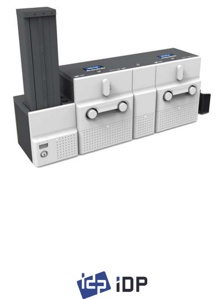
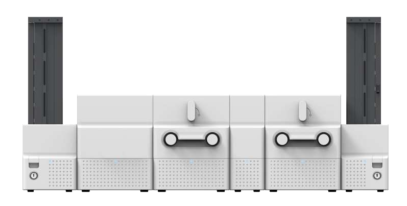
SMART-70 is a high-performance large capacity ID card printer designed by the unique modular
concept that can support various printer configurations to meet different user requirements. 500
cards can continuously be printed, laminated and encoded on various card. SMART-70 consists of
6 different modules (① Input Hopper, ② Encoding station, ③ Printer, ④ Flipper, ⑤ Laminator, ⑥
Output Hopper) that can be configured in various combinations according to different customer
requirements. Required modules can easily be added to extend functions depending on your
needs.
Figure 1 Combination of SMART-70
Key features of SMART-70 are as follows.
Convenience
SMART-70 is sleekly designed, such as modern household appliances, to provide user-
friendly environment with the maximum convenience. Status LED on all modules can
indicate the status of each module at all times. Also, LCD and buttons on Printer and
Laminator are for user to check the status and set the configuration. Card, print ribbon
and other consumables can be changed in intuitive way, and all modules are equipped
①
②
③
⑥
⑤
④
11
with physical locks to provide high security feature.
Clear printing
SMART-70 can print clear images on card by using IDP’s FINE Technology that can
exquisitely control the heat of print head depending on the picture.
High Speed
SMART-70 can print 200 cards/hour for color (YMCKO) and 1,000 cards/hour for
monochrome. Since each module can independently work, multiple cards can be
simultaneously printed, encoded and laminated by the pipeline processing for
enhancing issuance speed.
High Capacity
SMART-70 is designed to support 500 cards capacity in Input Hopper, Printer,
Laminator and Output Hopper. Once card, print ribbon and laminating film are replaced,
500 cards can be continuously issued. Also, cards can be loaded and stacked the up to
3000 cards by using multiple Input / Output Hopper.
Encoding
SMART-70 can encode magnetic stripe and smart cards by using Encoding Station or
the encoding options installed into Printer module. In case of using Encoding station,
magnetic stripe card, contact and contactless smart card can be encoded and 1D & 2D
barcode on card can be scanned. Also, magnetic stripe and contactless smart card
encoder can be installed in Printer module.
Energy Saving
In order to save energy, SMART-70 is designed to minimize unnecessary power
consumption when the system doesn’t work. Since SMART-70 Laminator uses the
instant direct heating mechanism developed by IDP, it requires no warming-up for
laminating and no additional power consumption for maintaining the temperature of
the laminate head while on standby.
Reliability
Since the metal frame, stainless steel shaft and ball bearing is used for the high
durability, SMART-70 can be stably operated under the harsh environments of the
massive issuance environment.
12
Scratch Free
SMART-70 can protect a card surface while the card is in SMART-70 for printing and
encoding. 500 cards can be loaded in Input Hopper but the cards can be taken out
from Input Hopper without scratch by using the patented load distribution structure of
IDP. Also, it is designed that inserted cards don’t get in contact with any other
components except the rollers for card feeding in Printer, Laminator and other module.
In Output Hopper, the stacked cards are lifted up for preventing scratch when a new
card is inserted into Output Hopper.
Software
Since the card design and DB (Database) software for card issuance as well as the
printer driver is provided free of charge, users will not need to purchase additional
software. Utility programs for adjusting the configuration and checking the status of
Printer and powerful SDK (Software Development Kit) for easily developing customized
applications are also provided without coast.
1.2 Modules
SMART-70 can organize the card issuing system by combining the 6 different modules. In this case,
Printer communicates with the PC and controls the other modules. If Laminator is used without
Printer, Laminator will control other modules. This chapter shows the features of each module.
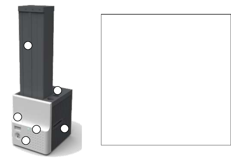
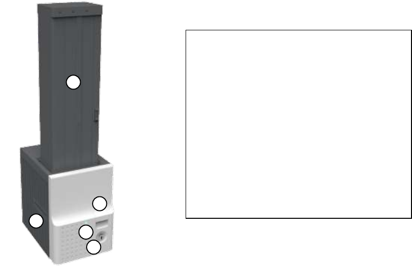
1.2.1 Input Hopper
SMART-70 Input Hopper can be loaded up to 500 cards and supply a card at a time. SMART-70
Input Hopper has the following features.
Cards can be conveniently loaded by using large capacity card cartridge which 500
CR80 cards (card thickness 0.8mm) can be loaded.
The gate of card cartridge can be easily adjusted depending on the thickness of card.
When card cartridge is taken out from Input Hopper, the gate of cartridge is
13
automatically closed for preventing the loss of cards.
In order to prevent the theft of cards, physical locking mechanism can prevent card
cartridge from being taken out from Input Hopper.
For solving the problem caused by dust, both sides of card are cleaned when the card
is supplied.
The cleaning device is easily managed by changing the disposable cleaning roller
included in new print ribbon package whenever print ribbon is changed.
Since cards in cartridge pushed by special structure of IDP’s patented technology, cards
are stably supplied even if the cards are stuck by the static.
500 cards are loaded, but the loaded cards don’t make scratch because the weight of
loaded cards is dispersed when the lowest card has to be supplied.
When card cartridge is empty, Input Hopper can automatically check and notify the
status.
Figure 2 Front side of Input Hopper
0
1
0
2
0
3
① Card cartridge
500 cards can be loaded.
② Disposable cleaning roller holder
Please install the disposable cleaning roller
included with new ribbon.
③ Cartridge release button
Please pull up card cartridge while pressing
cartridge release button.
④ Indicator LED
The status of Input Hopper is displayed by the
color.
⑤ Physical lock
Card cartridge is locked and can’t be taken out
from Input Hopper.
⑥ Card gate
Card is supplied to other module.
0
4
0
5
0
6
14
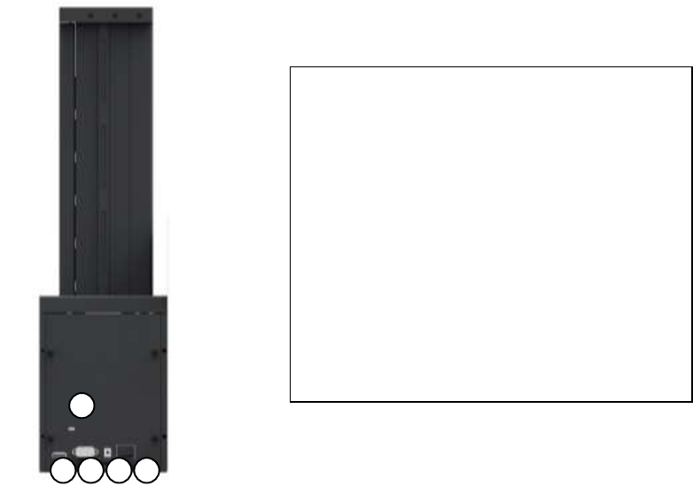
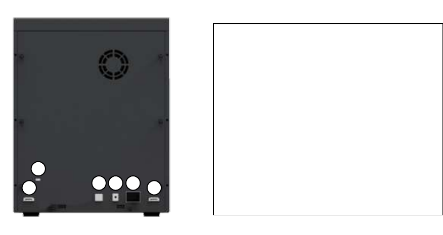
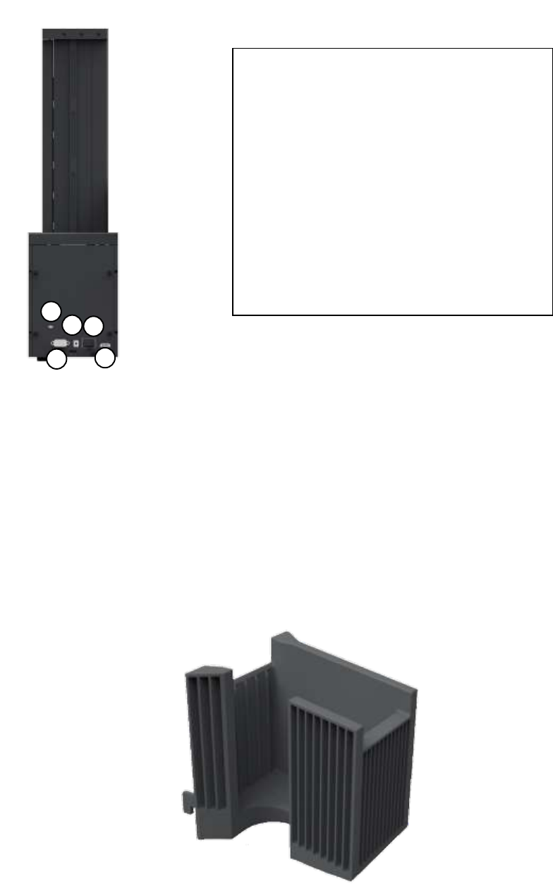
Figure 3 Rear side of Input Hopper
1.2.2 Encoding station (Being developed)
SMART-70 Encoding Station is designed to read barcode printed on card and support various
types of encoding. By using Encoding Station, multiple cards can be simultaneously printed and
encoded to enhance issuance speed.
Various optional encoders can be installed in Encoding Station as below. Optional encoding
modules can be purchased according to your needs.
Barcode reader
1D Barcode: Code32, Code39, Code93, Code128, Codaba, EAN 128, …
2D Barcode: PDF417, MicroPDF417, MaxiCode, DataMatrix, QR Code, …
Magnetic encoder
ISO7811 HiCo / LoCo Card
JIS2 Card
Contact smart card encoder
ISO 7816 A/B/C Card
0
1
0
2
0
3
0
4
0
5
① Kensington lock
Kensington lock is usable.
② Communication port
To communicate between SMART-70 modules,
please connect to an adjacent module.
③ Serial communication port
This port is used when an external device
controls Input Hopper.
④ Power port
Please connect the 24V DC power adaptor
provided with Input Hopper.
⑤ Power switch
Turn On/Off

15
ISO 7816 1/2/3/4 microprocessor Cards
Contactless smart card encoder
ISO 14443 A/B Card
Mifare, DESFire Card
ISO 18092(NFC) Card
Felica Card
Figure 4 Front side of Encoding Station
0
1
0
2
0
3
0
4
0
5
① Control panel LCD
The status of Encoding Station is displayed.
② Control panel buttons
Buttons are used to check configuration or
status.
③ Physical lock
Front cover is locked and can’t be detached.
④ Indicator LED
The status of Encoding Station is displayed by
the color.
⑤ Card gate
Card gate is to convey cards from module to
module.
16
Figure 5 Rear side of Encoding Station
1.2.3 Printer
SMART-70 Printer is the high-end printer which the IDP’s printing technologies are concentrated.
SMART-70 Printer can continuously print 500 cards of color or 3000 cards of mono, and the
magnetic stripe and contactless encoding option can be installed.
SMART-70 Printer has the following features.
LCD and 4 buttons on the control panel of Printer are for user conveniences and users
can easily check the status of Printer and adjust the configuration.
Indicator LED on the front side of Printer displays the status of Printer by using the
color, so user can intuitionally check the status of Printer.
For improving the convenience of changing print ribbon, ribbon cartridge is designed
as the drawer type and the print ribbon can easily be changed.
By using ribbon cartridge lock lever, ribbon cartridge can easily be locked and print
head can be moved up and down for the convenience of maintenance.
For the prevention of thefts, physical locking mechanism and Kensington lock are
designed and applied to Printer.
Ethernet port is installed by default and user can print and encode cards via network.
① Kensington lock
Kensington lock is usable.
② Communication port
To communicate between SMART-70 modules,
please connect to an adjacent module.
③ USB device port
Please connect to the USB host port of Printer
module.
④ Power port
Please connect the 24V DC power adaptor
provided with Encoding Station.
⑤ Power switch
Turn On/Off.
0
1
0
2
0
3
0
4
0
5
0
2

17
For massive card issuance, metal frame, stainless steel shaft, ball bearing and high
quality materials are used to increase the stability and reliability of Printer.
In order to prevent scratch on cards, Printer is designed that cards don’t get in contact
with any other components except rollers when cards are being fed in Printer.
High printing speed and improved printing algorithm can guarantee a more vivid and
fine printing quality.
Since card design and DB (Database) software for card issuance as well as printer
driver and utility programs are provided free of charge, additional software is not
needed to purchase.
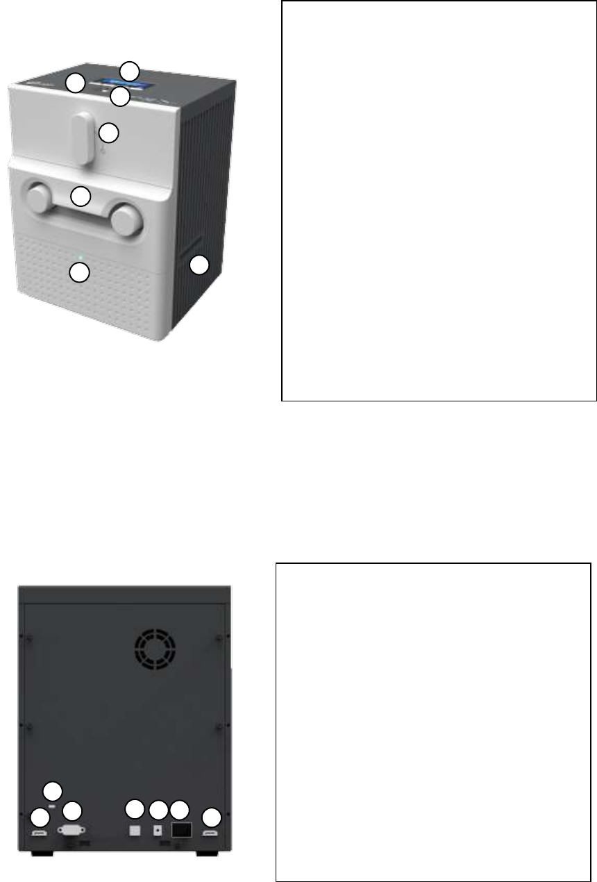
Figure 6 Front side of Printer
0
1
0
2
0
3
0
5
0
7
0
4
0
6
① Control panel LCD
The status of Printer is displayed.
② Control panel buttons
Buttons are used to adjust configuration and
check status.
③ Physical lock
Physical lock is to lock Printer and ribbon
cartridge.
④ Ribbon cartridge lock lever
To pull out ribbon cartridge, please turn lever
to the right 90 degrees for taking.
⑤ Ribbon cartridge
Color ribbon for 500 cards or mono ribbon for
3000 cards is loaded into ribbon cartridge.
⑥ Indicator LED
The status of Printer is displayed by the color.
⑦ Card gate
Card gate is to convey cards from module to
module.
18
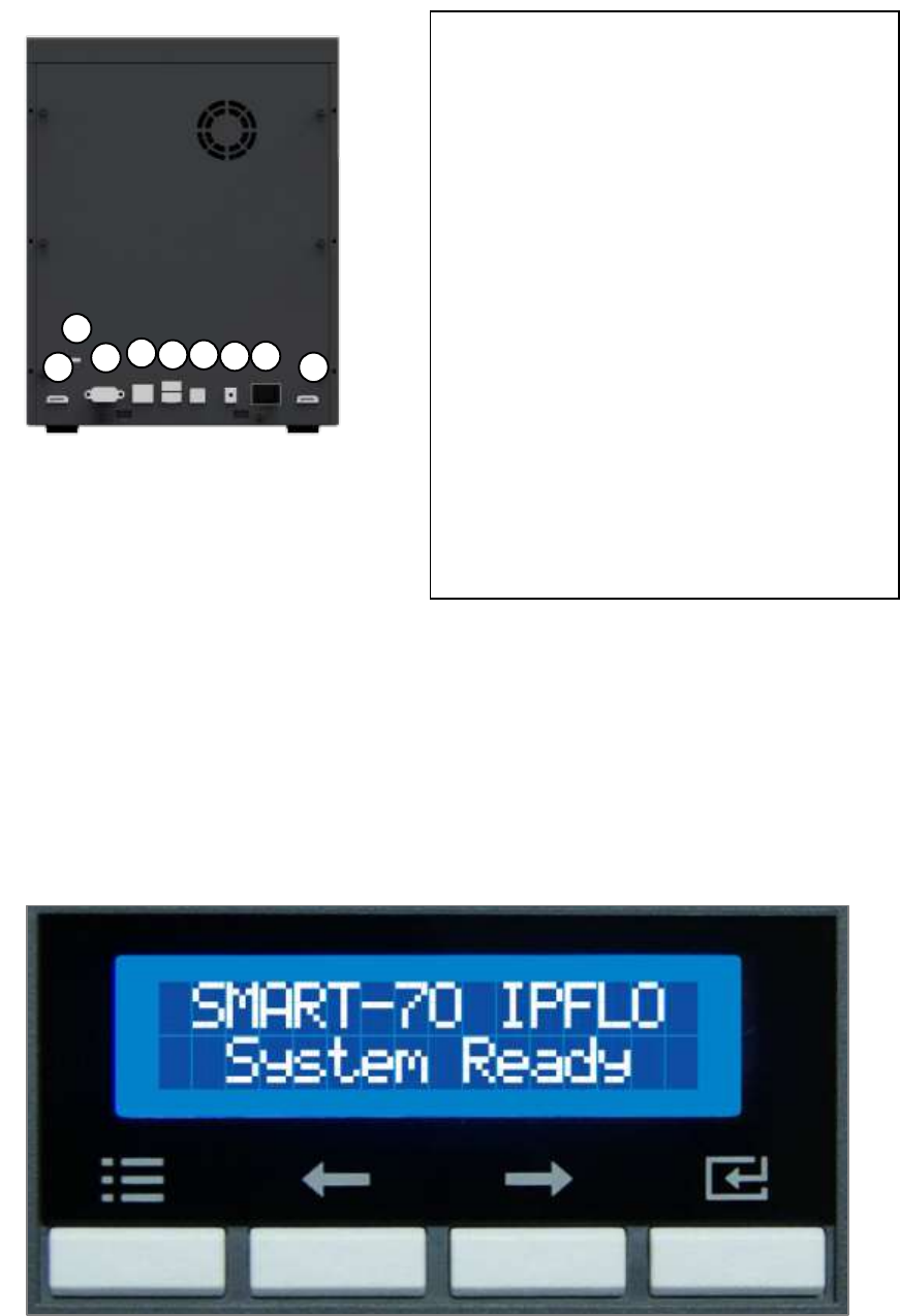
Figure 7 Rear side of Printer
Control panel of Printer consists of 2 lines LCD and 4 buttons. The 4 buttons have the functions as
shown in the figure 8.
Figure 8 Control panel of Printer
① Kensington lock
Kensington lock is usable.
② Communication port
To communicate between SMART-70 modules,
please connect to an adjacent module.
③ Serial communication port
This port is to communicate with external
device except SMART-70 modules.
④ Ethernet port
This port is for network communication.
⑤ USB host port
This port is for connecting to the USB device
port of Encoding Station.
⑥ USB device port
To communicate with PC, please connect to PC.
⑦ Power port
Please connect the 24V DC power adaptor
provided with Input Hopper.
⑧ Power switch
Turn On/Off.
0
1
0
2
0
3
0
4
0
5
0
2
0
6
0
7
0
8
Menu/Cancel
Left/Up
Right/Down
Select/OK

19
The menus of the control panel of Printer are as below table.
Menu
Submenu
Description
>System Config.
>>Combination
To set module combination. Refer to the chapter
2.1.10 for modules combination setting.
>>Operation Mode
To set Printer as a Master device. Default is Master.
>>Insert Dir
To set the direction of Card In. Default is the left.
>>Eject Dir
To set the direction of Card Out. Default is the right.
>>Auto Card In
To set the automatic card feeding when the card is
detected at the direction of Card In. Default is OFF.
>>UserCounterClear
To reset user issue count.
>Network Config.
>>DHCP
To set whether to use DHCP function. Default is On.
>>IP Address
IP address to be used when DHCP is OFF.
>>Network Mask
Network Mask to be used when DHCP is OFF.
>>Gateway
Gateway address to be used when DHCP is OFF.
>Print Config.
>>XStartPosition
To set the start position of the printing on the card’s
X-axis (shorter side).
>>YStartPosition
To set the start position of the printing on the card’s
Y-axis (longer side).
>>YEndPosition
To set the end position of the printing on the card’s
Y-axis.
>>YScale
To set the length of printed image on the card’s Y-
axis.
>>TotalDensity
To set the total printing density.
>>ColorDensity
To set the color density
>>BlackDensity
To set the resin black density.
>>OverlayDensity
To set overlay density.

20
>>RMP+
To adjust the force for pulling print ribbon during
printing when the residual quantity of print ribbon is
in its maximum quantity.
>>RMP-
To adjust the force for pulling print ribbon during
printing when the residual quantity of print ribbon is
in its minimum quantity.
>>RMM+
To adjust the force for pulling print ribbon during
alignment when the residual quantity of print ribbon
is in its maximum quantity.
>>RMM-
To adjust the force for pulling print ribbon during
alignment when the residual quantity of print ribbon
is in its minimum quantity.
>>HeadResister
To set resistance value of TPH (Thermal Print Head).
>Operation
>>Print Sample
To print a sample card.
>Information
>>Printer Serial
To show the serial number of Printer.
>>Firmware Ver.
To show the firmware version of Printer.
>>Head Serial
To show the serial number of TPH.
>>Ribbon Balance
To show the print ribbon type and balance.
>>IP Address
To show the current IP address of Printer.
>>Network Mask
To show the current Network mask of Printer.
>>Gateway
To show the current Gateway of Printer.
>>MAC Address
To show the MAC address of Printer.
>>User Count
To show the number of issued cards that user can
reset.
>>Factory Count
To show the number of accumulated issued cards
after factory shipment.
21
1.2.4 Flipper
SMART-70 Flipper can flip over a card for dual sided printing and laminating. The error card bin in
Flipper can collect 30 error cards (encoding failed cards) and the collected cards can be taken out
by opening the front cover of Flipper.
Figure 9 Front side of Flipper
Figure 10 Rear side of Flipper
① Kensington lock
Kensington lock is usable.
② Communication port
To communicate between SMART-70 modules,
please connect to an adjacent module.
③ Power port
Please connect the 24V DC power adaptor
provided with Flipper.
④ Power switch
Turn On/Off
0
1
0
2
0
3
① Physical Lock
Physical lock is to lock Flipper cover.
② Flipper cover
To take out error cards or fix problem, please
open Flipper cover by pulling out.
③ Indicator LED
The status of Flipper is displayed by the color.
④ Card gate
Card gate is to convey cards from module to
module.
0
4
0
1
0
2
0
3
0
4
0
2
22
1.2.5 Laminator
SMART-70 Laminator is the high performance laminator which cards are can be laminated with
high quality without warming-up by using the patented technology of the IDP’s “Instant direct
heating mechanism”. One roll of the holographic or clear laminating film can laminate 500 cards.
SMART-70 Laminator has following features.
LCD and 4 buttons on the control panel are for user conveniences and users can easily
check the status of Laminator and adjust configuration.
Indicator LED on the front side of Laminator displays the status of Laminator by using the
color, so user can intuitionally check the status of Laminator.
For improving the convenience of changing a laminating film, film cartridge is designed
as the drawer type and laminating film can easily be changed.
By using film cartridge lock lever, film cartridge can easily be locked and laminate head
can be moved up and down for the convenience of maintenance.
For the prevention of thefts, physical locking mechanism and Kensington lock are
designed and applied to Laminator.
For massive card issuance, metal frame, stainless steel shaft, ball bearing and high quality
materials are used to increase the stability and reliability of Laminator.
Conventional laminators must be needed warming-up time before laminating, but
SMART-70 Laminator can immediately laminate without having to wait by using IDP’s
Instant direct heating mechanism.
Instant direct heating mechanism of IDP uses bar-type laminate head to instantly increase
the temperature of laminate head and to reduce energy consumption to one-seventh
level compared with conventional method and to increase the lifespan of laminate head.
In order to prevent scratch on cards, Laminator is designed that cards don’t get in
contact with any other components except rollers when cards are being fed in Laminator.
23
Figure 11 Front side of Laminator
Figure 12 Rear side of Laminator
① Kensington lock
Kensington lock is usable
② Communication port
To communicate between SMART-70 modules,
please connect to an adjacent module.
③ Serial communication port
This port is to communicate with external
device except SMART-70 modules.
④ USB device port
When Laminator is used without the Printer,
this port is to communicate with PC.
⑤ Power port
Please connect the 24V DC power adaptor
provided with Laminator.
⑥ Power switch
Turn On/Off
0
1
0
2
0
3
0
5
0
7
0
4
0
6
0
1
0
2
0
3
0
2
0
4
0
5
0
6
① Control panel LCD
The status of Laminator is displayed.
② Control panel buttons
Buttons are used to adjust configuration and
check status.
③ Physical lock
Physical lock is to lock Laminator and film
cartridge.
④ Film cartridge lock lever
To pull out film cartridge, please turn lever to
the right 90 degrees.
⑤ Film cartridge
Laminating film for 500 cards is loaded into
cartridge. Ribbon cartridge in Printer can’t be
used for Laminator.
⑥ Indicator LED
The status of Laminator is displayed by the
color.
⑦ Card gate
Card gate is to convey cards from module to
module.
24
1.2.6 Output Hopper
SMART-70 Output Hopper can stack with 500 cards after printing, laminating and encoding.
SMART-70 Output Hopper has the following features.
Cards can be conveniently collected by large capacity cartridge which 500 CR80 cards
(card thickness 0.8mm) can be loaded.
When card cartridge is taken out from Output Hopper, the gate of card cartridge is
automatically closed for preventing the loss of cards.
In order to prevent the theft of cards, physical locking mechanism can prevent card
cartridge from being taken out from Output Hopper.
When card cartridge is full, Output Hopper can automatically check and notify the status.
When a card is inserted into Output Hopper, stacked cards are lifted up by the support
beam what is operated by internal CAM to protect card from scratch.
Same card cartridge is used for Input Hopper and Output Hopper, so card cartridge can
be shared.
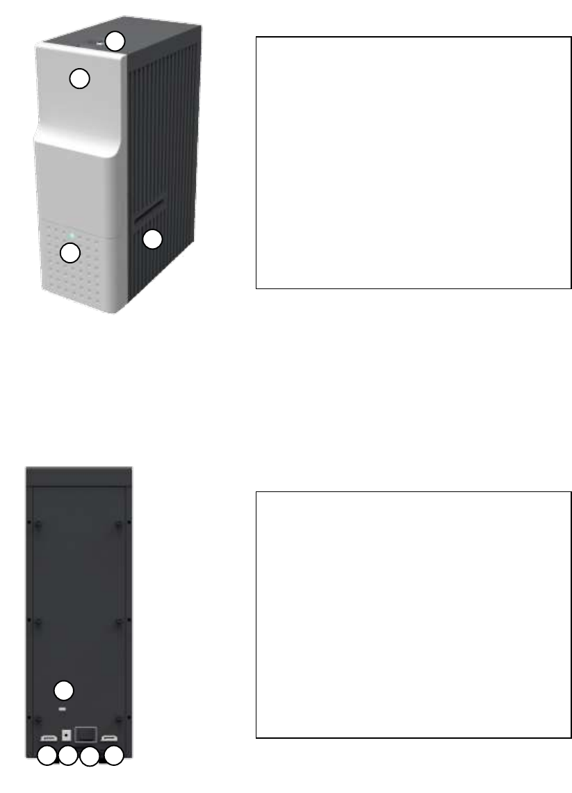
Figure 13 Front side of Output Hopper
0
1
0
2
0
3
0
4
0
5
① Card cartridge
500 cards can be loaded.
② Cartridge release button
Please pull up card cartridge while pressing
cartridge release button.
③ Indicator LED
The status of Output Hopper is displayed by
the color.
④ Physical lock
Card cartridge is locked and can’t be taken out
from Output Hopper.
⑤ Card gate
Card is inserted from other module.
25
Figure 14 Rear side of Output Hopper
1.2.7 Stacker
If Output Hopper is not needed, 100 cards can be ejected and loaded by using the Stacker
provided with Input Hopper.
Figure 15 Stacker
0
1
0
2
0
3
0
4
0
5
① Kensington lock
Kensington lock is usable.
② Serial communication port
This port is used when external device needs to
control Output Hopper.
③ Power port
Please connect the 24V DC power adaptor
provided with Output Hopper.
④ Power switch
Turn On/Off.
⑤ Communication port
To communicate between SMART-70 modules,
please connect to an adjacent module.
26
2. Installation and operation
2.1 Hardware installation
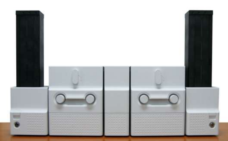
2.1.1 Placement of Modules
SMART-70 modules need to be placed on a flat table. Order of placing modules from left to right
is Input Hopper, Encoding Station, Printer, Laminator and Output Hopper. When some module is
not required, please remove unnecessary modules from above placing order. For example, if
Encoding Station and Laminator are not needed, Input Hopper, Printer, Flipper and Output Hopper
can be placed.
Figure 16 SMART-70 Placement of modules
27
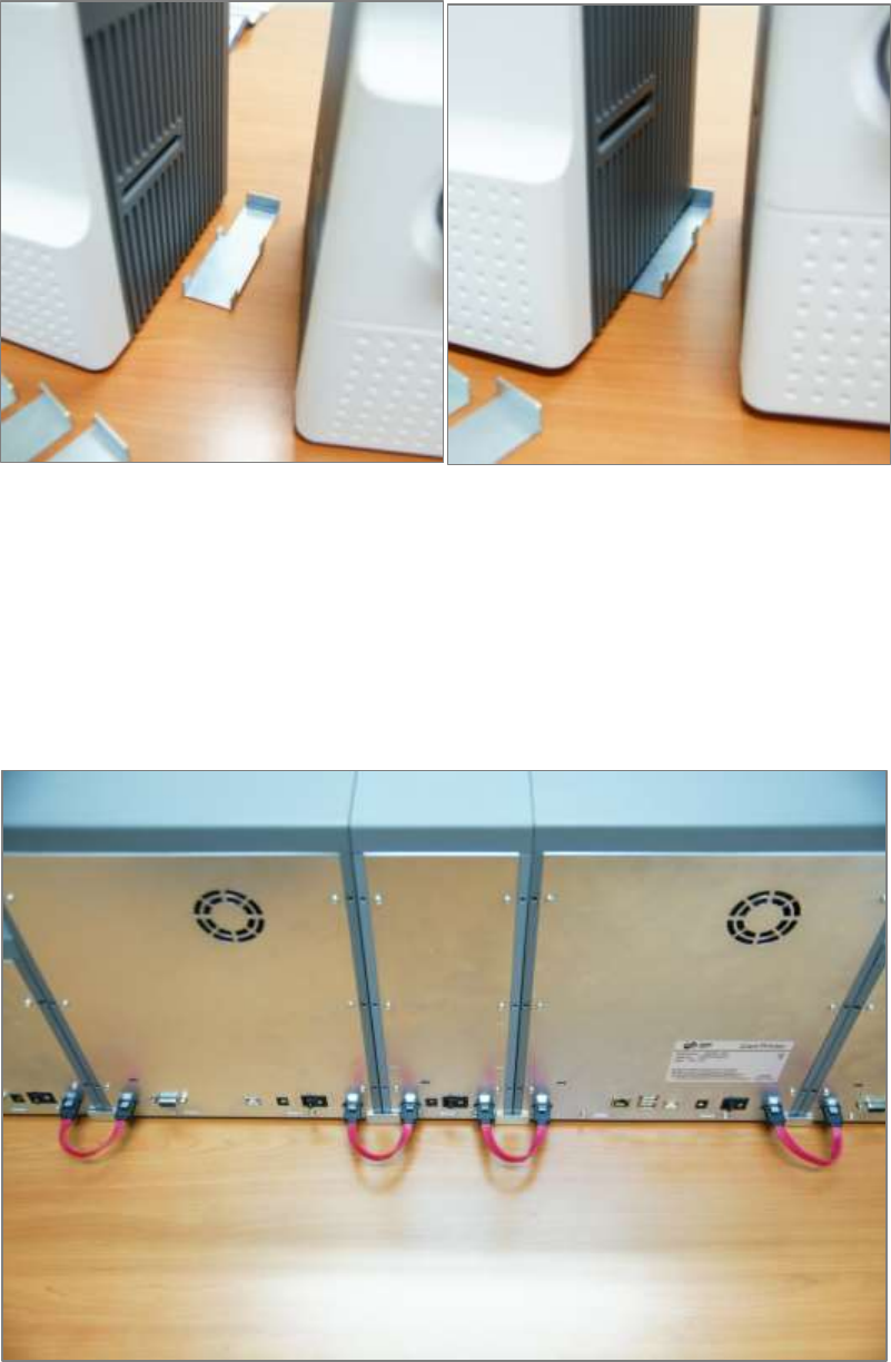
2.1.2 Module fastening
Binding cramp can fasten between SMART-70 modules. Please place the cramp on floor and put a
module on the cramp as shown as figure.
Figure 17 Module fastening
2.1.3 Module connection
Please connect the red communication cables provided with the modules to each module.
Figure 18 Module connection
28
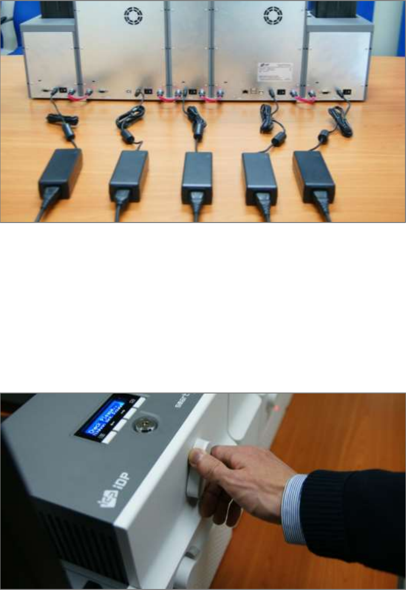
2.1.4 Power connection
Please connect the 24V DC power adaptors provided with each module to all modules. Printer
must be connected to the 24 DC power adaptor provided with Printer.
Figure 19 Power connection
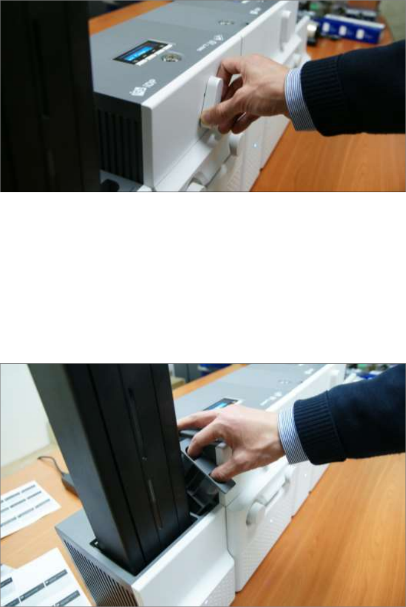
2.1.5 Print ribbon and laminating film installation
A. Please turn ribbon / film cartridge lock lever to the clockwise 90 degrees.
Figure 20 Ribbon / film cartridge unlocking
29
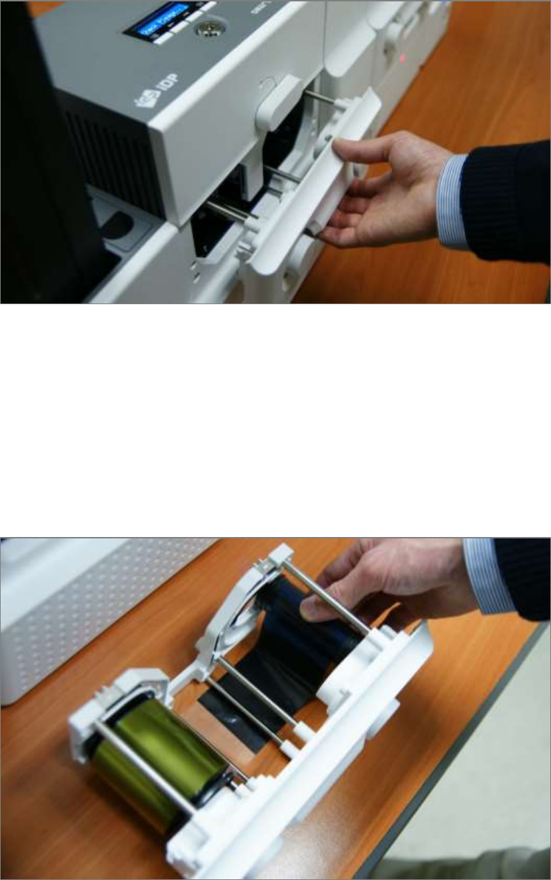
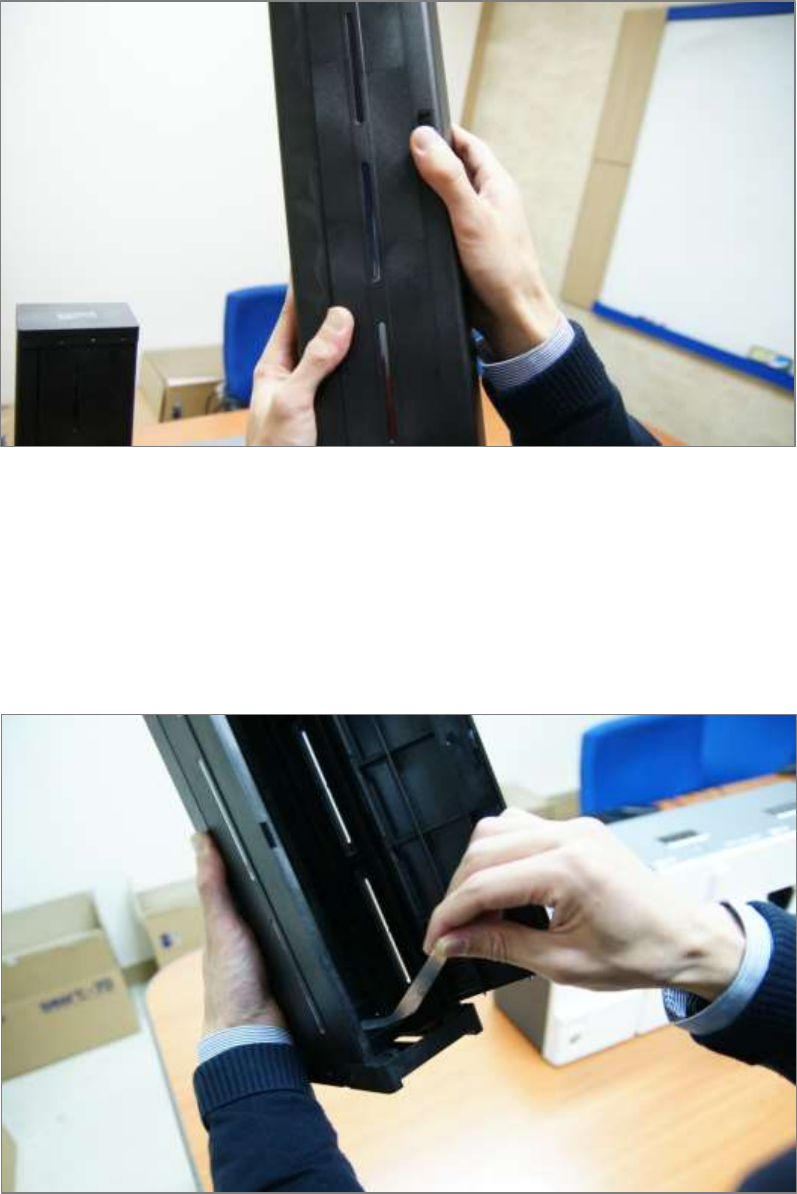
B. Please pull out ribbon / film cartridge.
Figure 21 Pulling out ribbon / film cartridge
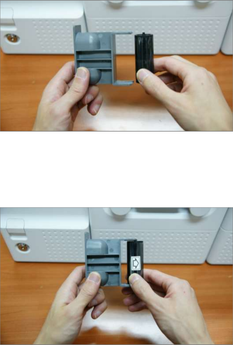
C. Please mount print ribbon / laminating film by pushing cores into cartridge from the side of
cartridge as figure. To properly mount print ribbon or laminating film, please refer to the install
guideline on the print ribbon or laminating film box. Ribbon cartridge in Printer is different with
film cartridge in Laminator, so the cartridges can’t be shared. The ribbon cartridge must be used
in Printer and the film cartridge must be used in Laminator.
Figure 22 Print ribbon / laminating film mounting
30
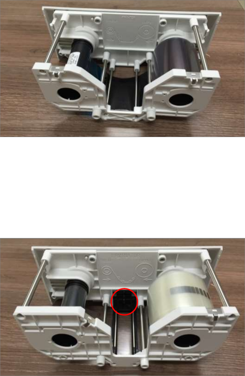
When print ribbon is being mounted, please refer to the mounting instruction on the inside of
ribbon cartridge as shown as figure.
Figure 23 Print ribbon mounting
When laminating film is being mounted, please refer to the mounting instruction on the inside of
film cartridge as figure. If vertical laminating position on card is needed to adjust, please use the
lever marked by red circle.
Figure 24 Laminating film mounting
31
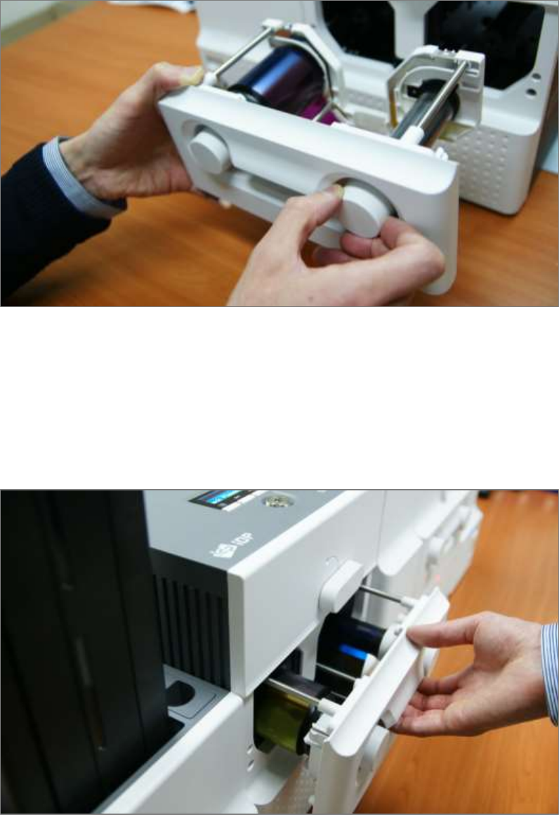
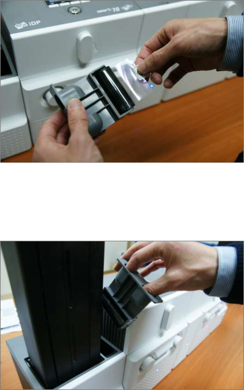
D. Please turn the dial on the right side of cartridge to tension print ribbon or laminating film as
figure.
Figure 25 Print ribbon / laminating film alignment
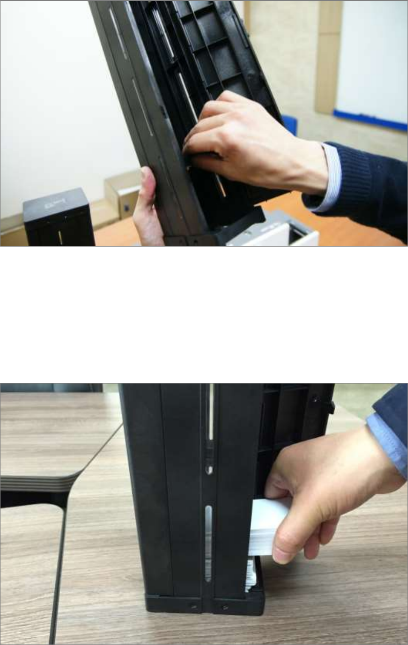
E. Please push ribbon or film cartridge into Printer or Laminator.
Figure 26 Ribbon / film cartridge insertion
32
F. Please turn ribbon / film cartridge lock lever to the counterclockwise 90 degrees, so the lever is
returned to the vertical.
Figure 27 Ribbon / film cartridge locking
2.1.6 Disposable cleaning roller installation
A. Please detach disposable cleaning roller holder from Input Hopper as figure.
Figure 28 Detachment of disposable cleaning roller holder
33
B. Please remove used disposable cleaning roller from holder.
Figure 29 Used disposable cleaning roller removal
C. Please mount a new disposable cleaning roller.
Figure 30 New disposable cleaning roller mounting
34
D. Please peel off the protector of disposable cleaning roller.
Figure 31 Removal of new disposable cleaning roller protector
E. Please install disposable cleaning roller holder into Input Hopper as figure.
Figure 32 Installation of disposable cleaning roller holder
35
2.1.7 Cards Loading
A. Please pull up card cartridge while pressing cartridge release button.
Figure 33 Card cartridge release from Input Hopper
B. Please adjust the gate of card cartridge depending on card thickness by using control lever.
Figure 34 Cards thickness adjustment
36
C. Please push the button on card cartridge down and open cartridge cover as figure.
Figure 35 Card cartridge open
D. Please remove the tape for fixing the weight in card cartridge as figure.
Figure 36 Removal of the tape for fixing the weight
37
E. Please pull up the weight and fix it to the top.
Figure 37 Card cartridge’s weight fixing
F. Please take care not to touch the surface of cards and load the cards into cartridge.
Figure 38 Card loading
38
G. Please put down the weight on loaded cards as figure.
Figure 39 Putting down the card cartridge’s weight
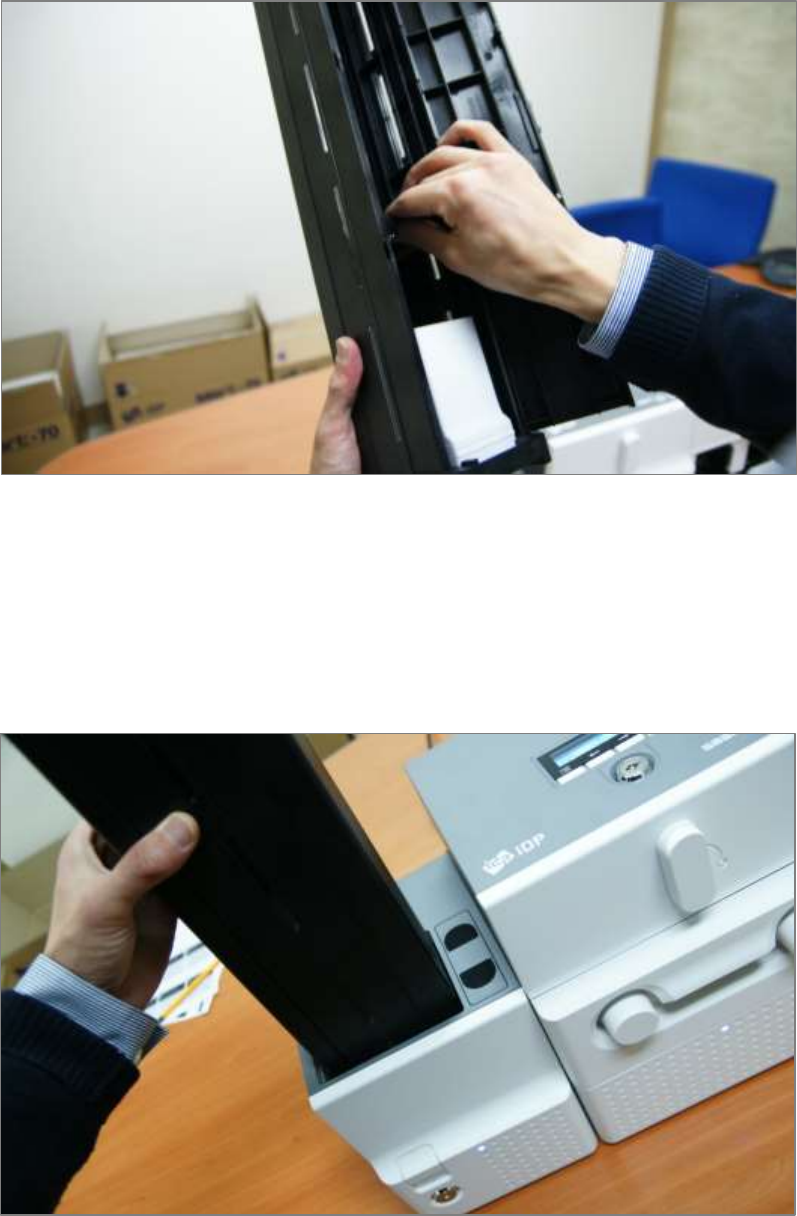
H. Please close card cartridge cover and put card cartridge into Input Hopper until click is heard.
Figure 40 Loading card cartridge into Input Hopper
39
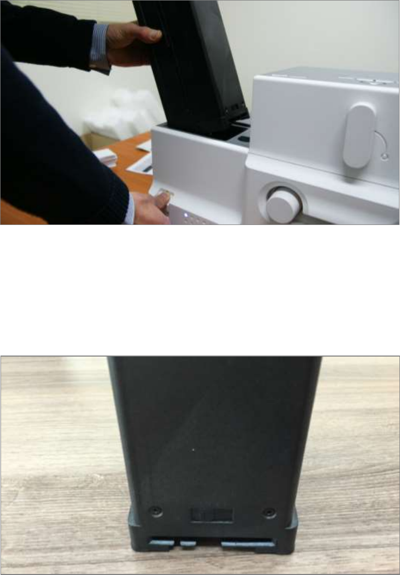
2.1.8 Loading card cartridge into Output Hopper
Please put an empty card cartridge into Output Hopper until click is heard. In order to take card
cartridge out, please pull up the cartridge while pressing cartridge release button.
Figure 41 Loading card cartridge into Output Hopper
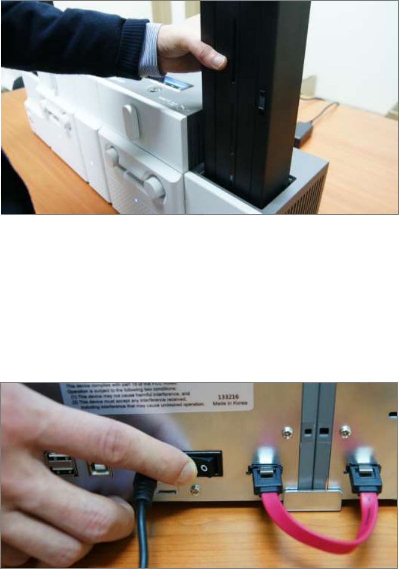
2.1.9 Power on
Please turn on the power switch on the rear side of all modules.
Figure 42 Power on
40
2.1.10 Module combination setting
Since SMART-70 is operated by the combination of multiple modules, the configuration for
multiple modules combination must be set during the first installation of the modules. Printer
module acts as master who is responsible to communicate with PC and control other modules,
and if Printer module is not connected, Laminator module will act as master. The configuration for
multiple modules combination can be set in the control panel of Printer module as below. SMART-
70 Printer searches connected modules in booting, if the combination of connected modules is
different with the configuration for multiple modules combination, Indicator LED is turned to
yellow and the message for checking modules combination is displayed. Please follow below steps
to set the configuration for multiple modules combinations for initial setting.
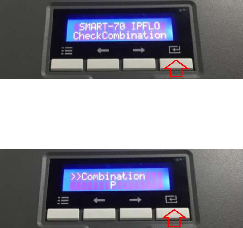
A. The modules combination is IPFLO (Input Hopper + Printer + Flipper + Laminator + Output
Hopper) but the configuration is different with the actually connected modules, so the
configuration for multiple modules combination must be set again.
Please press the [Select] button indicated by red arrow.
Figure 43 Modules combination checking
B. Existing modules combination is shown. Please press the [Select] button indicated by red arrow
to adjust the configuration for multiple modules combination.
Figure 44 Existing modules combination
41
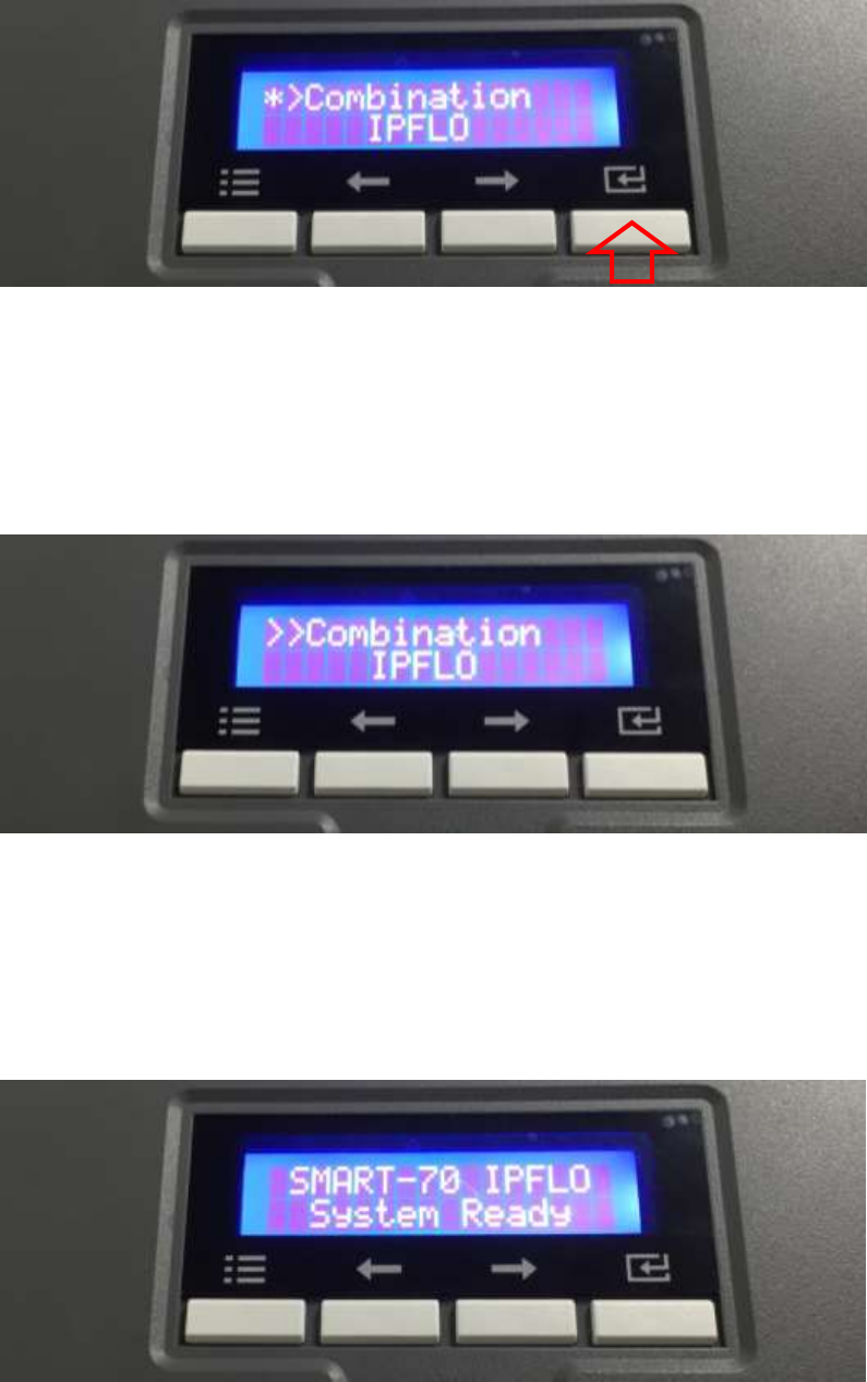
C. The detected modules combination is shown. Please press the [Select] button indicated by red
arrow to save the configuration for detected multiple modules combination.
Figure 45 Adjusted modules combination
D. The saved multiple modules combination is shown.
Figure 46 Saved module combination
E. Please wait a while until system is ready.
Figure 47 Completed module combination
42
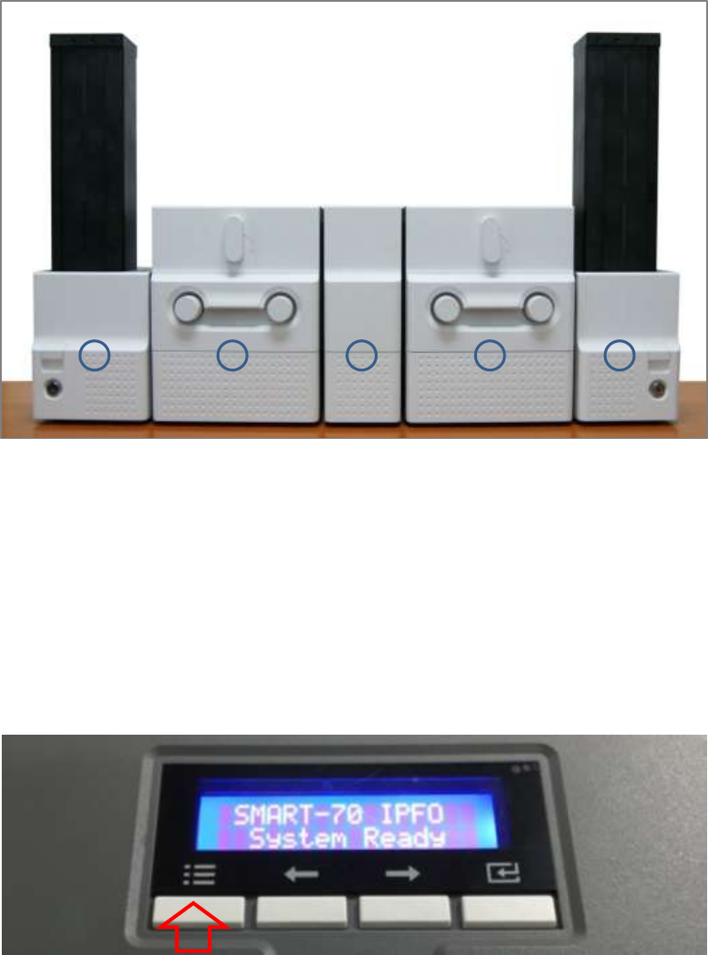
2.1.11 System status check
Please check that indicator LEDs on all modules are blue and the status of Printer and Laminator is
ready.
Figure 48 System status checking
2.1.12 Sample card printing
A. Please press the “Menu” button indicated by red arrow on Printer.
Figure 49 Printer menu
43
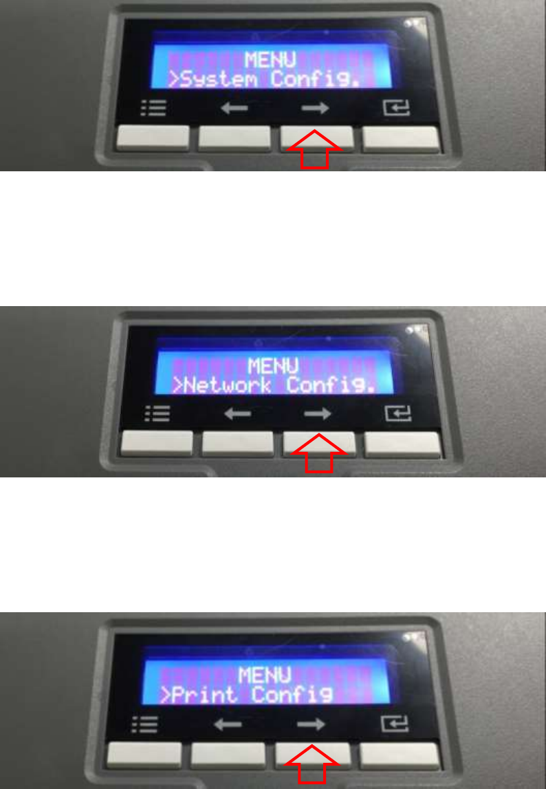
B. On “System Config” menu, please press the [→] button indicated by red arrow.
Figure 50 Printer menu (System Config)
C. On “Network Config” menu, please press the [→] button indicated by red arrow.
Figure 51 Printer menu (Network Config)
D. On “Printer Config” menu, please press the [→] button indicated by red arrow.
Figure 52 Printer menu (Printer Config)
44
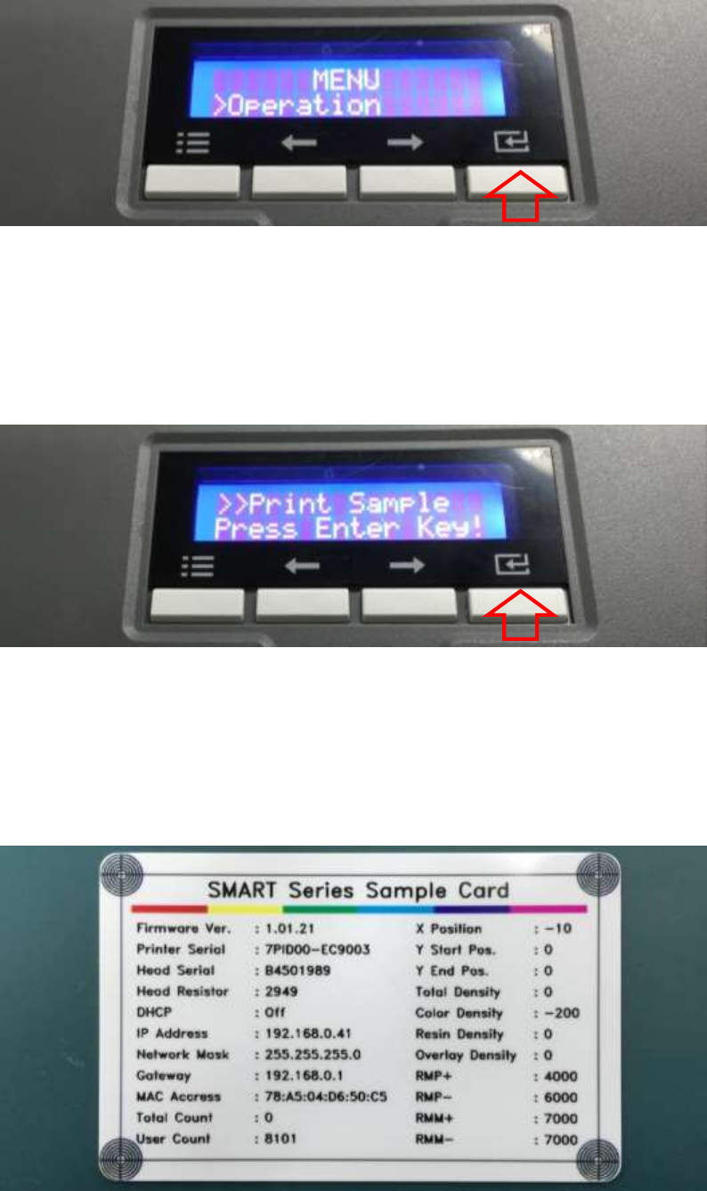
E. On “Operation” menu, please press the [Select] button indicated by red arrow.
Figure 53 Printer menu (Operation)
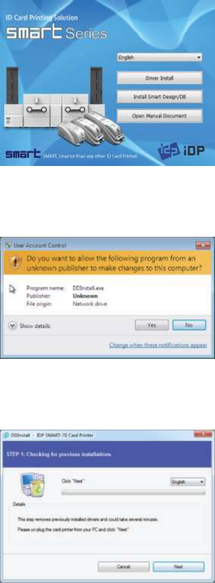
F. On “Print Sample” menu, please press the [Select] button indicated by red arrow.
Figure 54 Printer menu (Print Sample)
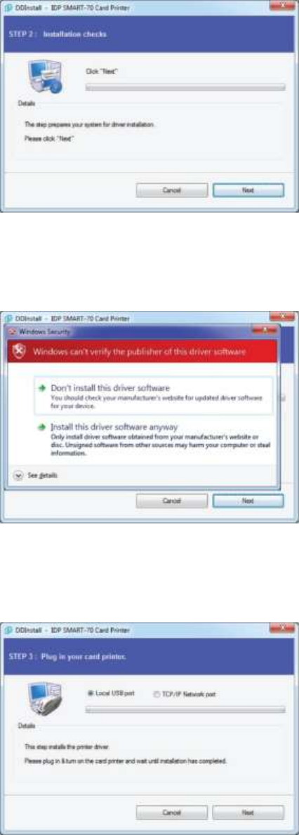
G. Please wait a while until sample card is printed as figure.
Figure 55 Sample Card
45
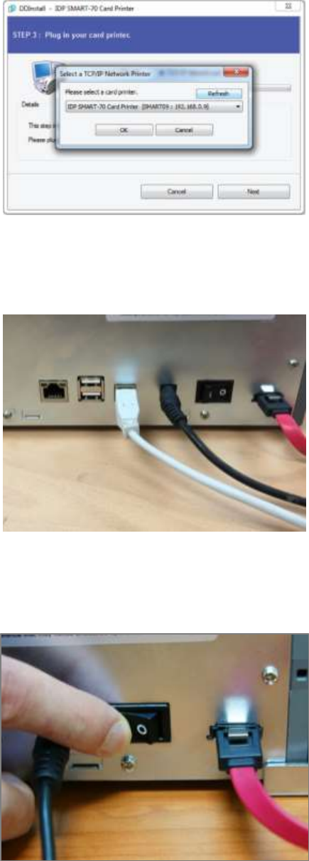
2.2 Software installation (Windows Vista/7/8)
Figure 56 Printer driver installation 1
2.2.1 Start-up window
Please insert the installation CD provided with
Printer and choose the language and click
“Driver Install” button.
*) When you want to install printer driver for
USB, please turn off Printer before installation.
When you want to install printer driver for
network, please turn on Printer.
Figure 57 Printer driver installation 2
2.2.2 User Account Control
When “User Account Control” window is
opened, please click “Yes”.
Figure 58 Printer driver installation 3
2.2.3 Driver Installation STEP 1
Please choose the language and click “Next”.
In STEP 1, previous installed printer driver is
automatically checked and removed.
46
Figure 59 Printer driver installation 4
2.2.4 Driver Installation STEP 2-1
When “Next” is clicked, printer driver
installation is prepared.
Figure 60 Printer driver installation 5
2.2.5 Driver Installation STEP 2-2
Please click “Install this driver software anyway”
when Windows Security window comes up,
Figure 61 Printer driver installation 6
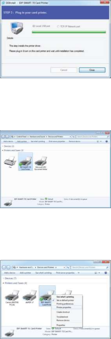
2.2.6 Driver Installation STEP 3-1
Please click “Next” when your Printer is
connected via USB.
If you want to install the printer driver for
network, please select the “TCP/IP Network
port” and select a proper Printer as shown in
the next step (2.2.7).
47
Figure 62 Printer driver installation 7
2.2.7 Driver Installation STEP 3-2
Please select a proper Printer on the list and
click “OK”.
(If Printer is not on the list of the network
printer select window, Printer is not connected
to network. So, please check the status of
network connection.)
Figure 63 Printer driver installation 8
2.2.8 USB port connection
Please connect USB cable to Printer.
(If your Printer is connected to network, please
check the status of network connection.)
Figure 64 Printer driver installation 9
2.2.9 Power on
Pease turn on all the modules.
48
Figure 65 Printer driver installation 10
2.2.10 Driver installation completion
Printer driver installation is completed after
turning on Printer. When driver installation is
completed, please click “Close”.
Figure 66 Printer driver installation 11
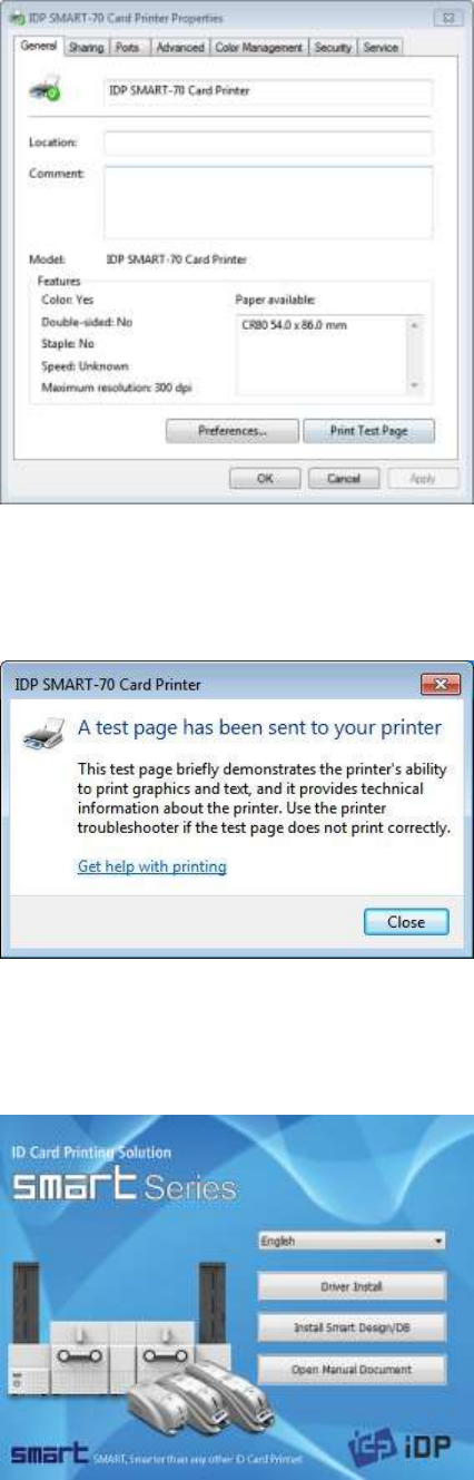
2.2.11 Driver installation check 1
Please open “Devices and Printers” window and
check that “IDP SMART-70 Card Printer” is
created properly.
Figure 67 Printer driver installation 12
2.2.12 Driver installation check 2
Please right click on “IDP SMART-70 Card
Printer” and select “Printer Properties”.
49
Figure 68 Printer driver installation 13
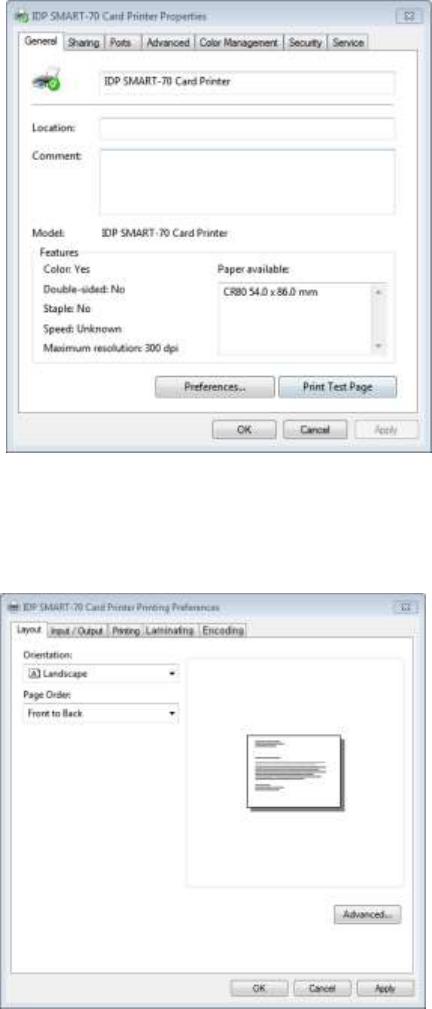
2.2.13 Driver installation check 3
Please select the “General” tab on “IDP SMART-
70 Card Printer” properties and click “Print Test
Page”.
Figure 69 Printer driver installation 14
2.2.14 Driver installation check 4
When test page is being printed, the widow for
checking printing status comes up. After
checking printed test card, if the test card is
properly printed, please click “Close”.
Figure 70 Application installation 1
2.2.15 Application installation 1
After printer driver installation, please install
SMART Design and DB by clicking “Install Smart
Application”.

50
Figure 71 Application installation 2
2.2.16 Application installation 2
When “Smart Application Install ShieldWizard”
window is opened, please click “Next”.
Figure 72 Application installation 3
2.2.17 Application installation 3
Please choose “I accept the terms of the license
agreement” and click “Next”.
Figure 73 Application installation 4
2.2.18 Application installation 4
Please select destination location for
application installation and click “Next”.

51
Figure 74 Application installation 5
2.2.19 Application installation 5
Please click “Install”.
Figure 75 Application installation 6
2.2.20 Application installation 6
After the application installation is completed,
please click “Finish” and use the installed
application.
52
3. Driver configuration
SMART-70 Printer can print cards by selecting various required properties. To adjust printer properties,
please open the Devices and Printers window and right click on “IDP SMART-70 Card Printer” and
select “Printer Properties”.
3.1 Printing preferences
Figure 76 Printer properties window
3.1.1 Printing Preferences
Please click “Printing Preferences” on the
“General” tab of Printer Properties window.
Figure 77 Layout
3.1.2 Layout
The print orientation (Landscape or Portrait) can
be selected.
To apply your selection, please click “OK”.
53
3.1.3 Advanced setup
For Advanced setup, please click the “Advanced” button on “Printing Preferences” window and you
can adjust the advanced setting.
Reset Default Values: Advanced setting is reset to the default values.
Color Correction: Adjusting gamma value of each color panel can change color sense. The
higher gamma value is the darker color. The absolute printing density can be adjusted by using
“CardPrinter70Setup” utility.
- Main [-100:100]: To adjust the gamma values of all panels.
- Yellow [-100:100]: To adjust the gamma value of the yellow panel.
- Magenta [-100:100]: To adjust the gamma value of the magenta panel.
- Cyan [-100:100]: To adjust the gamma value of the cyan panel.
- Black [-100:100]: To adjust the gamma value of the resin black panel.
- Overlay [-100:100]: To adjust the gamma value of the overlay panel.
Position Processing: The printing position between panels can be adjusted. If the value is
higher, the positions are more accurate but the color sense may be a little lower.
- Color [-32:32]: To adjust the printing position of the color panels (yellow, magenta and cyan).
- Mono [-32:32]: To adjust the printing position of the resin black panel.
- Overlay [-32:32]: To adjust the printing position of the overlay panel.
Resin Black (K) Processing: The method to extract the data to be printed by the resin black is
specified.
- Text [0:100]: To set the density criteria for extracting the text to be printed by the resin black.
- Dot [0:100]: To set density criteria for extracting the pixels to be printed by the resin black.
- Threshold [0:100]: To set density criteria for printing by the resin black when the dithering is
performed by using the Threshold.
- Dithering Degree [0:100]: To set sharpness when the dithering is performed by using the
Random.
- Resin Extraction: Method to extract the data for the resin black.
> Black object: Text, line, etc. Black objects are extracted.
> Black Text: Text is only extracted.
54
> Black Dots: All black dots are extracted.
> Not Use: No extraction.
Rewritable Controls: This property is only for rewritable printer.
- Erase Density [0:100]: To set the temperature to erase the contents on rewritable card.
Wait Option: This option can set the card’s waiting time at each encoding position when the
smart card is encoded without using SDK. One contactless smart card encoder can be installed
into SMART-70 Printer. One contactless and one contact smart card encoder can be installed
into SMART-70 Encoding Station.
When this option is set and the SDK is not used for encoding, the program which the smart
card is recognized and encoded within the specified waiting time must be developed by
yourself because the card is only waiting for a specified time at the encoding position.
- Wait at Internal Module Contactless Encoding Position [On/Off]: To set that the contactless
smart card is waiting at the contactless smart card encoding position in Printer.
- Wait at External Module Contactless Encoding Position [On/Off]: To set that the
contactless smart card is waiting at the contactless smart card encoding position in Encoding
Station.
- Wait at External Module Contact Encoding Position [On/Off]: To set that the contact smart
card is waiting at the contact smart card encoding position in Encoding Station.
> Card Side [Front/Back]: To set the direction of card when the card is waiting.
> Wait Position [-100:100]: To adjust the card position from the previous waiting position of
card to the left or the right (unit is 0.1mm).
> Wait Time [0:1000]: To set the waiting time of card (unit is a second).
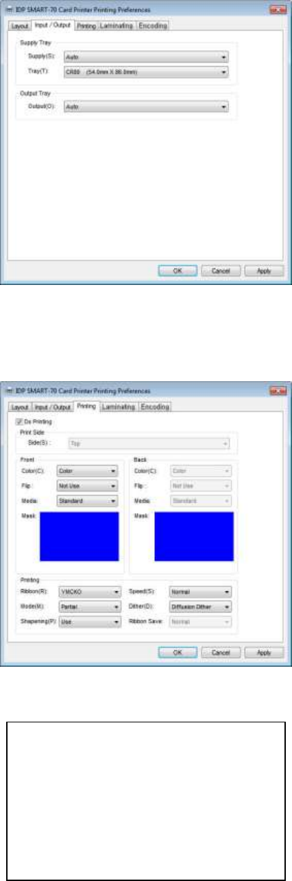
55
Figure 78 Input / Output settings
3.1.4 Input / Output settings
Supply Tray
Supply: If there is one Input Hopper, please
select “Auto”. If there are multiple Input
Hoppers, please select the Hopper which
will be used.
Tray: Please select “CR80” because SMART-70
only supports CR80 cards.
Output Tray
Output: If there is one Output Hopper select
“Auto”. If there are multiple Output
Hoppers, please select the Hopper which
will be used.
Figure 79 Printing settings
3.1.5 Printing settings
Do Printing: To set whether print or not.
Print Side: To set the single sided or dual sided
printing when Flipper is installed.
Front / Back
Color: To set the color or mono printing.
Flip: To turn the printed image on card.
Mask: To set the printing area on card. The
predefined masks (normal card, smartcard,
magnetic stripe card, etc.) or user defined
mask cab be used.
Printing
Ribbon: The print ribbon type is used for
printing and can be automatically
recognized.
Speed: To set the printing speed.
Mode: To set the all or partial printing.
Dither: Set the dithering types.
Sharpening: To calibrate the printed image
sharpness.
Ribbon Save: To set that the card is printed
by using the split function when the mono
ribbon is used.
User defined mask uses BITMAP file (1012 x
636 pixels).
Blue(RGB(0,0,255)) : Print and Overlay
Light blue(RGB(0,255,255)) : Overlay only
Pink(RGB(255,0,255)) : Print only
Yellow(RGB(255,255,0)) : Florescent only
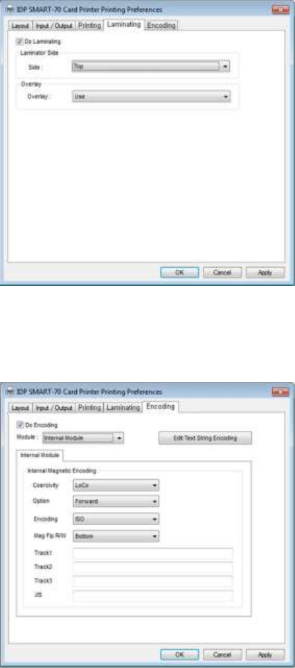
56
Figure 80 Laminating settings
3.1.6 Laminating settings
This tab will be created only when SMART-70
Laminator module is connected.
Do Laminating: To set whether laminate
or not.
Laminator Side: To set the laminating side of
card (top, bottom and both sides).
Overlay: To set whether overlay panel is
printed or not. Default is no overlay when the
card is laminated. We recommend no overlay
when the card is laminated.
Figure 81 Encoding settings
3.1.7 Encoding settings
This tab will be created only when SMART-70
Magnetic Encoding option is installed.
Do Encoding: To set whether encoding or not.
Module: To set whether the internal module
(Printer) or the external module (Encoding
Station) is used.
Coercivity: To set the type of the magnetic
stripe cards for encoding.
LoCo: 300, 600 Oe.
HiCo: 2760 Oe.
SpCo: 4000 Oe.
Auto: Automatic encoding depending on a
used magnetic stripe card type.
Option: To set the encoding direction
(Forward / Backward / Bitmode).
Encoding: To set the encoding protocol
(ISO / Bally’s).
Mag Flip R/W: To set the encoding side of
magnetic stripe card.
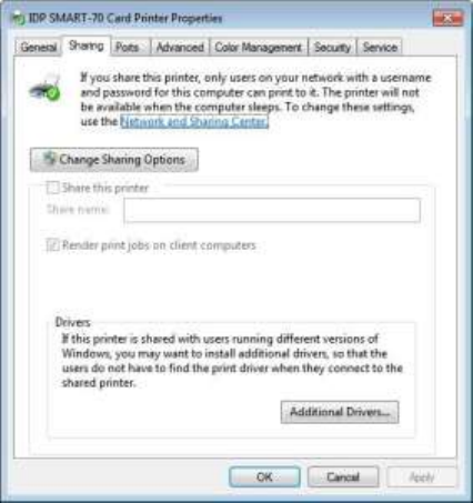
57
3.2 Other settings
Figure 82 Printer sharing settings
3.2.1 Sharing
Printer can be shared via network by setting
the option of printer sharing on the Sharing
tab.
Default is “Not sharing”.
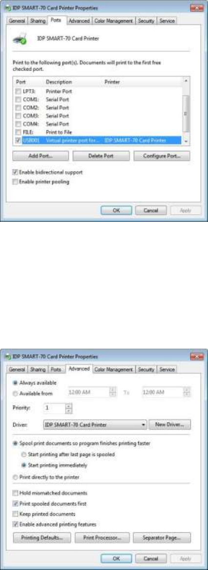
58
Figure 83 Ports setting
3.2.2 Ports
The Port tab shows which port is connected to
SMART-70 Printer. On Figure, USB001 Virtual
printer port is connected because SMART-70
Printer was connected via USB.
(Caution! The adjustment on the ports setting
by user is not recommended because the port
is automatically set.)
Figure 84 Advanced settings
3.2.3 Advanced
The working time, priority order, spool and etc.
can be set in “Advanced” tab. The Advanced
setting follows MS Windows standard. If you
want to change the setting, please refer to the
MS Windows manual.
(No adjustment on the Advanced setting is
recommended.)
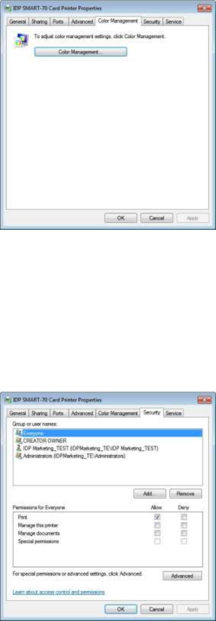
59
Figure 85 Color Management settings
3.2.4 Color Management
The proper color profile for Printer can be set
on the Color Management tab. For supporting
the optimized color printing, SMART-70 Printer
can automatically set the color profile
depending on the ribbon type loaded in Printer
because the ribbon type is automatically
recognized.
(No adjustment on the Color Management
setting is recommended.)
Figure 86 Security setting
3.2.5 Security
The access control and permissions for Printer
can be set. According to the authority, the
printing, management and special authority can
be permitted.
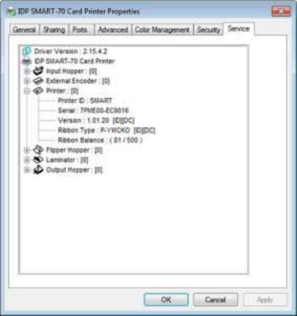
60
Figure 87 Printer status check
3.2.6 Printer status check
The serial number, ID, driver version, firmware
version, ribbon type and balance of all
connected modules can be checked on the
Service tab.
4. SMART-70 Utilities
The installation CD of SMART-70 Printer includes utilities for printer setting, test and firmware upgrade.
This chapter explains the SMART-70 utilities.
4.1 Printer setting
SMART-70 Printer is manufactured and shipped with optimized setting on each one. By the way,
printer setting can be adjusted by using CardPrinter70Setup utility included in the Installation CD
after disassemble and assemble of printer, replacement of some parts or when the adjustment of
printer setting is needed. Printer setting can be adjusted by using CardPrinter70Setup as below.
4.1.1 CardPrinter70Setup
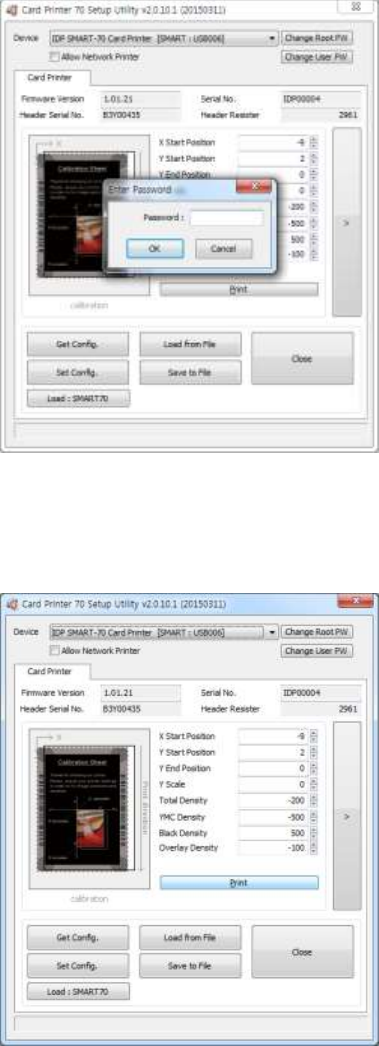
61
Figure 88 CardPrinter70Setup Log-in
Password input window is displayed when you run
this program. If the correct password is inputted,
the recorded setup values in SMART-70 Printer are
shown and the setup values can be adjusted.
The password for SMART-70 Printer is saved to
the SMART-70 Printer. When the SMART-70
Printer is connected to another PC, the saved
password in the SMART-70 Printer is required to
run this utility and adjust the Printer setting.
(Since there is no default password in SMART-70
Printer, please click “OK” if password have never
been set.)
Figure 89 CardPrinter70Setup Start
When you are successful to login, the basic setup
of Printer is shown as Figure 89.
4.1.2 Basic Setup
The basic setup of CardPrinter70Setup shows the firmware version, serial number and etc. of
the connected SMART-70 Printer, frequently used setting values (printing position, density and
etc.) can be adjusted.
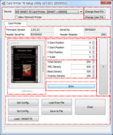
62
Figure 90 Basic Setup of CardPrinter70Setup
① To show connected Printer.
Device: The Printer that the adjustment is needed can be selected by using the pull-down
menu. “IDP SMART-70 Card Printer” is the connected Printer’s name. “SMART” is the
connected Printer’s ID, “USB006” is the connected port.
Allow Network Printer: If the Allow Network Card Printer is selected, Printers connected via
network also appear in the “Device” list.
② To set administrator password and user password.
Change Root PW: To set administrator (root) password. This password is used to verify user
authority for CardPrinter70Setup and is also required as administrator password when the
User Authentication option on Security is set on advanced setup.
(When Printer is installed at the place where security is required, please set password at the
same time with the installation of Printer.)
Change User PW: To set user password for user authentication. This password is required
as user password when the User Authentication option on Security is set on advanced
setup.
③ The firmware version, serial number of Printer, serial number of TPH, resistance value of
TPH, type of TPH is shown.
④ The printing area on card is shown. It shows exaggeratingly for user convenience and is not
real position.
⑤ To set the printing area on card. Please set it properly to print on an entire card because
SMART-70 is a direct thermal card printer. When you click “⑦ Print”, a card is printed as
like “④ example”. Please set values properly that all circles of each corner are printed and
①
②
③
④
⑤
⑥
⑦
⑧
⑨
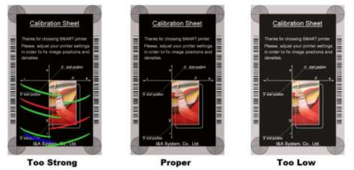
63
blank spaces are narrower than 0.5mm on the top and the bottom of a card. Please set
values by following order.
X Start Position: Please set the right and the left of printing position on card properly by
adjusting X position.
Y Start Position: Please set the start position of printed example image and blank space in
the top is 0.4mm ~ 0.5mm.
Y End Position: Please set the end position of printed example image and blank space in
the bottom is 0.4mm ~ 0.5mm. It is recommended to set bigger value for “Y scale” than
default.
Y Scale: Please set to print all circles in the bottom of card.
⑥ To set printed density. SMART-70 enables to set different density for each color, resin
black and overlay. So, proper setting on each density is needed for high quality. Please
optimize the quality by adjusting each value. To optimize, you repeatedly adjust the density
and print a Calibration card by using color ribbon and clicking “⑦ Print”, and please check
the printed state until you get the optimum.
Total Density: To set all of the density (Color, Black and Overlay) at one time.
YMC Density: To set color density. Please maximize YMC density as you can, which enables
to extend range of color and to print vivid images. If it is too strong, green or red marks are
appeared as Figure 91. If it is too weak, the print quality will be dull.
Figure 91 Color density
Black Density: To Set resin black density. In the picture, barcode is printed by resin black.
When density is too strong, barcode is printed too thick. When density is too weak, barcode is
too thin. Please adjust resin black density to print clear barcode. Please refer following
pictures.
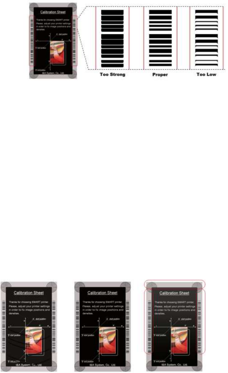
64
Figure 92 Resin Black density
Overlay Density: To set overlay density. Please adjust it until overlay is printed on surface
regularly. If it is too strong, it is hazy and marks are appeared. If it is too weak, overlay panel
is not printed edge areas. You can check it with printed card under the light.
Too Strong Proper Too Low
Figure 93 Overlay density
⑦ To print calibration card for adjusting the printing position and density.
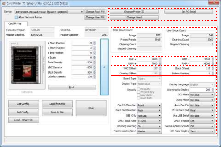
65
⑧ To show advanced setup.
(The advanced setup for expert options is not recommended to adjust.)
⑨ To load or save the setup values.
Get Config.: To get values from current connected Printer.
Set Config.: To set values to current connected Printer.
Load from File: To load setup values from file.
Save to File: To save setup values to file.
Load Default: To reset setup values to default. After loading default, all setup values must
be adjusted again. Load Default is not recommended.
Close: To close CardPrinter70Setup.
4.1.2 Advanced Setup
Expert setup of SMART-70 Printer can be adjusted on advance setup. If you are unsure, please
contact your dealer.
①
②
③
⑤
④
66
Figure 94 Advanced Setup
① To set Printer ID, PC Serial and Print Head register after replacing.
Change Printer ID: When SMART-70 is used by SDK, unique ID for SMART-70 Printer is set
regardless of whether it is connected via USB or what IP address is. It is useful to connect and
use several Printers. Factory default is “SMART”.
Set PC Serial: One of security functions. This function can be only used when Printer is
connected via USB and the Printer can be used with a specific PC. It is activated when “Set
PC Serial” is clicked after “PC Authentication” of ⑤ Security is set and rebooted. At that
time, the specific information of connected PC is saved to SMART-70 Printer and the saved
information is used to authenticate the connected PC.
Change Header: When thermal print head is replaced, the print head information must be
registered for optimal printing quality. Please change print head’s serial number, resistance
value and type in the Change Head Dialog window after click “Change Head”.
To show how many cards are issued with SMART-70 Printer. “Total Issue Count” is the number
of issued cards after factory shipment. “User Issue Count” is the number of issued cards after
replacing print head. When the print head is replaced, please initialize the number by setting
“Reset User Issue Count” in the Change Head Dialog window after clicking “Change Head” of
①.
② SMART-70 Printer controls motor for the best printing quality. “RMP+”, “RMP-“, “RMM+” and
“RMM-“ is necessary variables to control ribbon motor. Please do not adjust the variables
because the printing quality is affected.
When the normal printing speed is set, “YMC Offset”, “Black Offset” and “Overlay Offset” is
added to the YMC Density, Black Density and Overlay Density and printed on card. “Ribbon
Position” is to align the panel of ribbon on the card. Please use the default setting.
③ Please refer as below for other values.
Board Type: To set the mainboard type of SMART-70 Printer. Please do not change.
Display Type: To set the LCD type of SMART-70 Printer. Please do not change.
Display Language: To select the display language on the LCD of SMART-70 Printer. Please do
not change.
Security: SMART-70 Printer provides several ways to set a security function for authentication
and access control.
PC Auth.: Printer can only be used with specific PC. To activate this option, “Set PC Serial” is
clicked to save the specific PC’s information into Printer.
Physical Key: When physical key is installed into SMART-70, this option can set to activate
Printer by using the key.
User/Root Authentication: This option can set to activate Printer by using User and
67
Administrator (Root) password.
DCL Mode: When SDK is used to print cards with DCL mode, printer driver doesn’t need to
be installed. If the DCL mode is set to “Use”, printer driver is not installed on Windows.
Dump Mode: Log data can be recorded into Printer.
Card In Direction: To set the direction that card is fed.
Auto Card In: When the card is detected at card gate, the card is automatically moved into
Printer.
Card Out Direction: To set the direction that card is ejected.
Error Card Out: To set the direction which error card (encoding failed card) is ejected.
SBS Only: This option is only activated when SDK is used to print card. Printer driver can’t be
used when this option is set.
Use USB Serial: When SMART-70 Printer is connected to USB, Printer transmits the USB serial
number to PC. Default is the same number used by all SMART-70. To connect multiple
SMART-70 Printers to only one PC via USB, Please set this option to “USE” for using unique
serial numbers for each Printer.
UART Baud Rate: To set the communication speed (Baud rate) of the external device
connected to Printer by serial.
UART Bypass: When Printer is communicated with an external device by serial interface, the
commands are passed without any processing.
Cleaning Warning: After a certain number of printings, Printer is contaminated and needed
to clean for keeping the Printer in the best condition. If cleaning is required, please set how
to display the warning message.
Normal Ribbon Search: To set that SMART-70 can search the panel of ribbon more
accurately in ribbon searching.
Printer Master/Slave: SMART-70 Printer can variously be configured according to your needs
and two Printers can be connected and used. In this case, this option is used to set the
Printer connected to PC via USB to “MASTER” and set the other Printer to “SLAVE”.
LCD Error Display: To set the displayed message type on the LCD of Printer when error
occurs in Printer.
68
4.2 Printer test
Since card printer basically use standard printer device driver, card can be printed by the same
method as a general paper printer. By the way, if encoding options are installed into card printer,
appropriate device driver for each encoding option must be installed and each encoding option
must be properly operated. In this case, encoding options can be controlled by “Card Printer SDK”.
CardPrinter70Test utility is to test the functions of SMART-70 Printer and is developed by “SMART-
70 Printer SDK”.
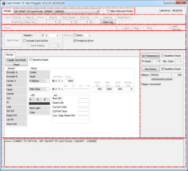
69
Figure 95 CardPrinter70Test
① Select Printer: To select a Printer for test. In the picture. “IDP SMART-70 Card Printer” is the
connected Printer’s name, “SMART” is the connected Printer’s ID and “USB006” is the
connected port.
② Basic Control: To execute basic functions of Printer (Card In/Out, Print Head Up/Down, etc.).
③ Print: To print a CSD file which is designed by SMART Design.
④ Batch Job: To execute the job of ⑤ repeatedly.
⑤ Monitor: To check the working status of sensors and motors.
⑥ Printer Status: To check the status of Printer.
⑦ Message: To display messages when this utility is run.
4.2.1 Printer selection and basic control
When CardPrinter70Test is run, Printers connected via USB are automatically searched and can be
selected by priority. After setting "Allow Network Printer", all Printers connected via USB and
network can be selected. Other Printer can be selected by using pull-down menu. When a printer
is connected to this utility, the basic control, print and monitor can be tested.
The basic control functions will be provided later.
①
③
④
⑤
⑦
②
⑥
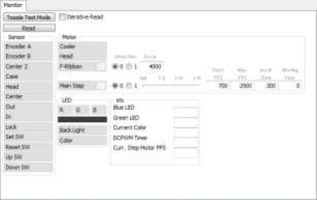
70
4.2.2 Print Test
Print is to print a CSD file designed by SMART Design. This function will be provided later.
4.2.3 Batch Job
Batch job is to test the status of encoding and decoding continuously. This function will be
provided later.
4.2.4 Monitor
Monitor is to check the status of Printer in the “Monitor” tab.
Toggle Test Mode: To switch between normal mode and board test mode.
Read: To read the status of sensors and motors from Printer.
Iterative Read: When the “Iterative Read” is set, the status of sensors and motors is periodically
read from Printer.
Figure 96 Monitor
4.2.5 Printer status
“Get Temperature” is to get and display the temperature of Thermal Print Head. When the
“Realtime Check” is set, the temperature of Thermal Print Head is got and displayed in real time.
“Get Status” is to get and display the status of Printer.
Status Codes are as below.
#define S7PS_M_SBSRUNNING 0x0000000000000001 // SBS (Step by Step) command execution
71
#define S7PS_M_CARDMOVE 0x0000000000000002 // Move to print
#define S7PS_M_CARDIN 0x0000000000000004 // Card In
#define S7PS_M_CARDOUT 0x0000000000000008 // Card Out
#define S7PS_M_THEAD 0x0000000000000010 // Thermal Head Up/Down
#define S7PS_M_SEEKRIBBON 0x0000000000000020 // Ribbon Search
#define S7PS_M_MOVERIBBON 0x0000000000000040 // Ribbon Move
#define S7PS_M_PRINT 0x0000000000000080 // Printing
#define S7PS_M_MAGRW 0x0000000000000100 // Magnetic Read/Write
#define S7PS_M_RECVPRINTDATA 0x0000000000000200 // Printing data Receiving
#define S7PS_M_INIT 0x0000000000000400 // Initializing
#define S7PS_S_INSTALLINTENCODER 0x0000000000008000 // Internal Encoder Installed
#define S7PS_S_INSTALLEXTHOPPER 0x0000000000010000 // External Input Hopper Installed
#define S7PS_S_INSTALLEXTSTACKER 0x0000000000020000 // External Output Hopper Installed
#define S7PS_S_INSTALLEXTENCODER 0x0000000000040000 // External Encoder Installed
#define S7PS_S_INSTALLEXTLAMINATOR 0x0000000000080000 // External Laminator Installed
#define S7PS_S_INSTALLEXTFLIPPER 0x0000000000100000 // External Flipper Installed
#define S7PS_S_INSTALLEXTETC 0x0000000000200000 // External Other Device Installed
#define S7PS_S_CASEOPEN 0x0000000000400000 // Case Open
#define S7PS_S_SOFTLOCKED 0x0000000000800000 // Soft Locked
#define S7PS_S_KEYLOCKED 0x0000000001000000 // Key Locked
#define S7PS_S_DETECTCARD 0x0000000002000000 // Card Detected Internal Sensor
#define S7PS_S_DETECTFRONTDEVICE 0x0000000004000000 // Front Device Detected
#define S7PS_S_DETECTREARDEVICE 0x0000000008000000 // Rear Device Detected
#define S7PS_S_CLEANWARNING 0x0000000010000000 // Printer Cleaning Warning
#define S7PS_S_HAVEPRINTDATA 0x0000000020000000 // Have Printing Data
#define S7PS_S_SBSMODE 0x0000000040000000 // SBS Mode
#define S7PS_S_TESTMODE 0x0000000080000000 // Test Mode
Error Codes are as below.
#define S7PS_E_CARDIN 0x0000000100000000 // Card In Error
#define S7PS_E_CARDMOVE 0x0000000200000000 // Card Move Error
72
#define S7PS_E_CARDOUT 0x0000000400000000 // Card Out Error
#define S7PS_E_THEADLIFT 0x0000000800000000 // Thermal Head Up/Down Error
#define S7PS_E_PRINT 0x0000004000000000 // Printing Error
#define S7PS_E_MAGRW 0x0000008000000000 // (Internal) Magnetic Read/Write Error
#define S7PS_E_MAGREADT1 0x0000010000000000 // (Internal) Mag. Track 1 Read Error
#define S7PS_E_MAGREADT2 0x0000020000000000 // (Internal) Mag. Track 2 Read Error
#define S7PS_E_MAGREADT3 0x0000040000000000 // (Internal) Mag. Track 3 Read Error
#define S7PS_E_CONNECTEXTHOPPER 0x0000080000000000 // External Hopper Connection Error
#define S7PS_E_CONNECTEXTSTACKER 0x0000100000000000 // External Stacker Connection Error
#define S7PS_E_CONNECTEXTENCODER 0x0000200000000000 // External Encoder Connection Error
#define S7PS_E_CONNECTEXTLAMINATOR 0x0000400000000000 // External Laminator Connection Error
#define S7PS_E_CONNECTEXTFLIPPER 0x0000800000000000 // External Flipper Connection Error
#define S7PS_E_CONNECTEXTETC 0x0001000000000000 // External Other Device Connection Error
#define S7PS_E_EXTPRESETMATCH 0x0002000000000000 // External Preset Device Connection Error
#define S7PS_E_RIBBONSEEK 0x0080000000000000 // Ribbon Search Error
#define S7PS_E_RIBBONMOVE 0x0100000000000000 // Ribbon Move Error
#define S7PS_F_THEADABSENT 0x0200000000000000 // Uninstalled Thermal Head
#define S7PS_F_THEADOVERHEAT 0x0400000000000000 // Overheat Thermal Head
#define S7PS_F_RIBBONABSENT 0x0800000000000000 // No Ribbon
#define S7PS_F_PRINTDATA 0x1000000000000000 // Printing Data Error
#define S7PS_F_INCORRECTPASSWORRD 0x2000000000000000 // Incorrect Password
#define S7PS_F_CONFIG 0x4000000000000000 // Configuration Fail
4.3 Firmware upgrade
SMART-70 Modules’ firmware can be updated by using CardPrinter70Firmware. Since SMART-70 is
operated by combined several modules, firmware of each module can be individually upgraded as
necessary.
When CardPrinter70Firmware is run, the window as below is shown.
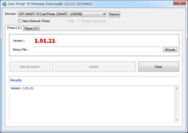
73
Figure 97 CardPrinter70Firmware
Devices: To select the Printer that firmware will be upgraded.
Allow Network Printer: To set that Printers connected via network are displayed in Devices.
Printer [ 0 ] / … : To select the modules of SMART-70 system that firmware is upgraded.
Version: To displays the current firmware version of selected Printer.
Binary File: To select the new firmware file. Please click “Browse” button to search and select
the new firmware file.
Manual Update: To upgrade the firmware manually.
Update: To upgrade the firmware automatically. Update for automatic upgrading is generally
recommended.
Close: To close this utility.
Message: Necessary information is displayed when the firmware is being upgraded.
4.3.1 Printer connection
After SMART-70 Printer is connected to PC and the connected Printer is selected on Devices of
CardPrinter70Firmware, all modules of SMART-70 System are displayed as tabs.
SMART-70 System is combined by "Printer module 0" and "Flipper module 0" as Figure.
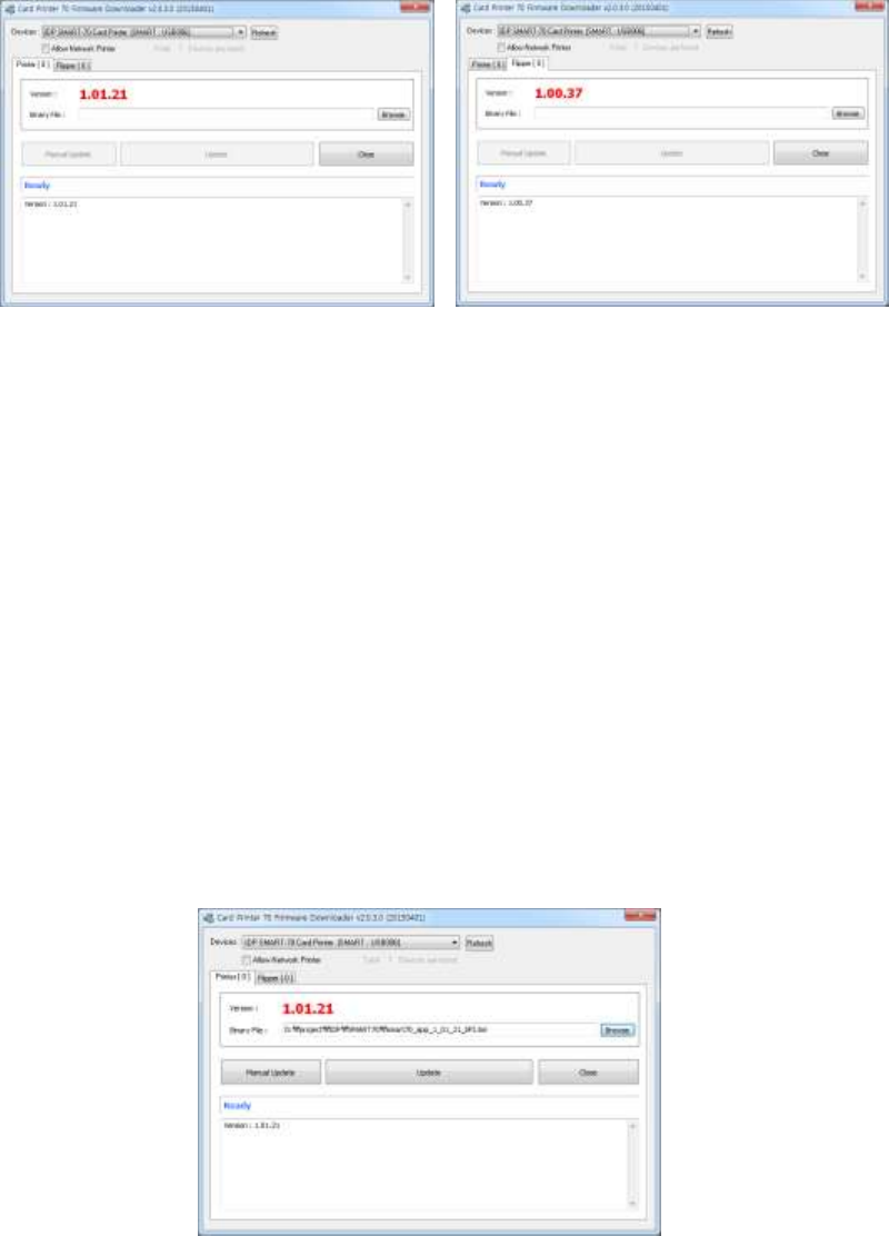
74
Figure 98 Modules of SMART-70 System (Printer, Flipper)
4.3.2 Module Firmware Upgrade
After clicking the tab of the combined modules of SMART-70 System such as “Printer [ 0 ]” or
Flipper [ 0 ]”, please click “Browse” and search and select the new firmware for the module. After
selecting the new firmware, “Manual Update” and “Update” is activated. Please click “Update” for
automatic firmware upgrade, and the Printer is automatically rebooted after firmware upgrade.
(Caution. Please do not do another job until the firmware upgrade is successfully completed and
do not turn off the Printer.)
Figure 99 Ready for firmware upgrade
In case there is some problems in automatic firmware upgrade, please click “Manual Update” to
manually upgrade firmware. According to the pop-up window as below figure, firmware can
manually be upgraded by clicking “Transfer” after the Printer is manually turned on and off.
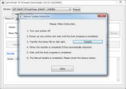
75
Figure 100 Manual firmware upgrade
5. Troubleshooting
5.1 Printing quality
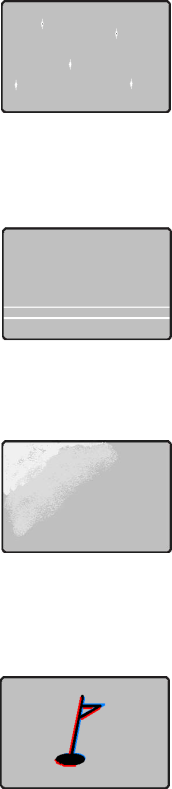
76
5.1.1 Unprinted or wrong colors printed spot
The card surface is contaminated by foreign substance.
After checking the status of card, please change it
to another clean card.
The cleaning roller is contaminated.
After checking the cleaning roller. If the cleaning roller
is contaminated too much, please change a disposable
cleaning roller.
Dust is too much in printer.
Please clean the inside of printer by using cleaning kit.
5.1.2 Unprinted horizontal line
The print head is contaminated by foreign substance.
Please clean the print head by using cleaning kit.
The print head is damaged.
Please contact the local supplier to replace the print head.
The ribbon cartridge is improperly installed.
Please check the installation status of ribbon cartridge
and whether the print ribbon has wrinkles.
5.1.3 Blurry or unstable print
Uneven or bad surface of card.
Please change cards.
Too high or too low setting of color density.
The printing density of your printer must be adjusted.
Please contact the local supplier.
The print head is contaminated by foreign substance.
Please clean the print head by using cleaning kit.
5.1.4 Not aligned color print
Non-standard or bad cards.
Please change cards
(ISO CR80 card (54mm x 86mm) must be used).
Figure 102 Printing quality trouble 2
Figure 103 Printing quality trouble 3
Figure 101 Printing quality trouble 1

77
Uneven or bad surface of card.
Please change cards.
Card feeding or printing roller is contaminated.
Please clean the rollers by using cleaning kit.
Outdated printer.
Please contact the local supplier.
5.1.5 Unplanned color print
Non-standard or bad cards.
Please change cards
(ISO CR80 card (54mm x 86mm) must be used).
Card feeding or printing roller is contaminated.
Please clean the rollers by using cleaning kit.
Malfunctioned ribbon sensors.
Please contact the local supplier to replace the sensors.
Outdated printer.
Please contact the local supplier.
5.2 Card supply
5.2.1 Card is not supplied or 2 cards are supplied from Input Hopper
Non-standard or bad cards.
Please change cards
(ISO CR80 card (54mm x 86mm) must be used).
Card cartridge is improperly loaded.
Please properly load the card cartridge into
Input Hopper again.
Card thickness of card cartridge is improperly set.
Please properly adjust the card thickness control lever
depending on the thickness of card. In case card is not
supplied, please adjust the lever to the right.
In case 2 cards are supplied, please adjust the lever
to the left.
5.3 Card jam
5.3.1 Card jam in Input Hopper
Figure 104 Printing quality trouble 4
Figure 105 Printing quality trouble 5
Figure 106 Card supply problem 1
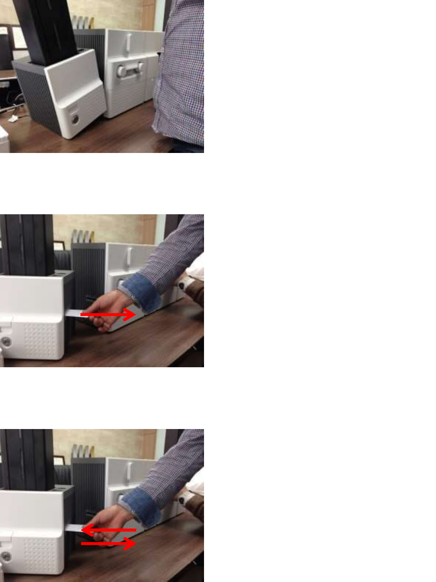
78
Figure 107 Card jam in Input Hopper 1
A. Card jam in Input Hopper 1
Please separate Input Hopper as Figure
after disconnecting power adaptor and
communication cable at rear side.
Figure 108 Card jam in Input Hopper 2
B. Card jam in Input Hopper 2
If card is jammed on the card gate of
Input Hopper as Figure, please remove the
jammed card by pulling out.
Figure 109 Card jam in Input Hopper 3
C. Card jam in Input Hopper 3
If card is not on the card gate of Input Hopper
but card cartridge can’t be pulled up, please
push in and pull out a new card as Figure.
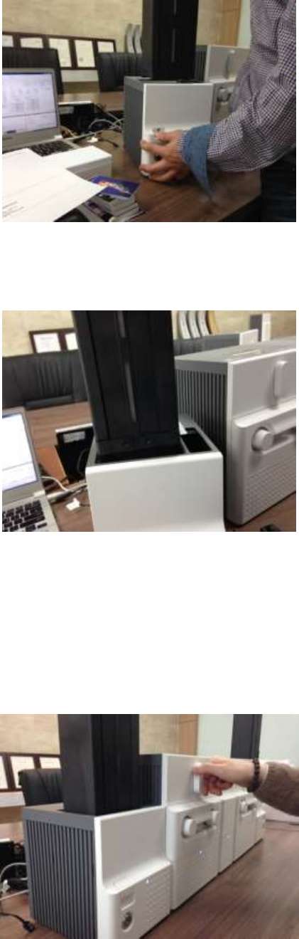
79
Figure 110 Card jam in Input Hopper 4
D. Card jam in Input Hopper 4
Please pull up card cartridge while pushing the
cartridge release button as Figure.
Figure 111 Card jam in Input Hopper 5
E. Card jam in Input Hopper 5
If card is jammed at the gate of card cartridge
as Figure, please remove the jammed card by
pulling out.
5.3.2 Card jam in Printer
Figure 112 Card jam in Printer 1
A. Card jam in Printer 1
Please turn the ribbon cartridge lock lever to
the clockwise 90 degrees as Figure.
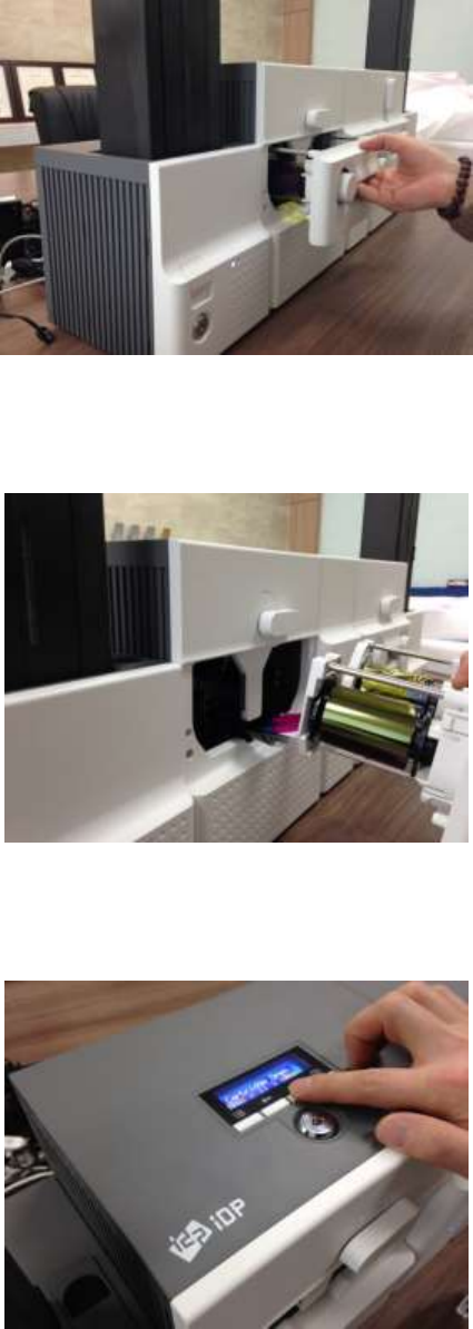
80
Figure 113 Card jam in Printer 2
B. Card jam in Printer 2
Please pull out the ribbon cartridge as Figure.
Figure 114 Card jam in Printer 3
C. Card jam in Printer 3
If print ribbon is stuck to card or coiled on
rollers as Figure, the ribbon cartridge may not
be pulled out easily. In this case, please cut the
ribbon or slowly pull out the ribbon cartridge
while pressing the “” or “” button on the
control panel of Printer little by little.
Figure 115 Card jam in Printer 4
D. Card jam in Printer 4
To remove a jammed card in Printer, please
press the “” button on the control panel of
Printer until the jammed card is completely
ejected.
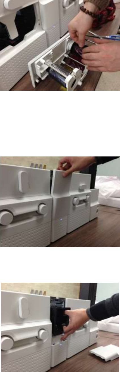
81
Figure 116 Card jam in Printer 5
E. Card jam in Printer 5
If print ribbon is cut, please stick the cut ribbon
together by using a sticky tape and then turn
the dial on ribbon cartridge until unused panel
of ribbon is on take-up core.
5.3.3 Card jam in Flipper
Figure 117 Card jam in Flipper 1
A. Card jam in Flipper 1
Please open the cover of Flipper by pulling as
Figure.
Figure 118 Card jam in Flipper 2
B. Card jam in Flipper 2
Please pull out the error card bin in Flipper as
Figure.
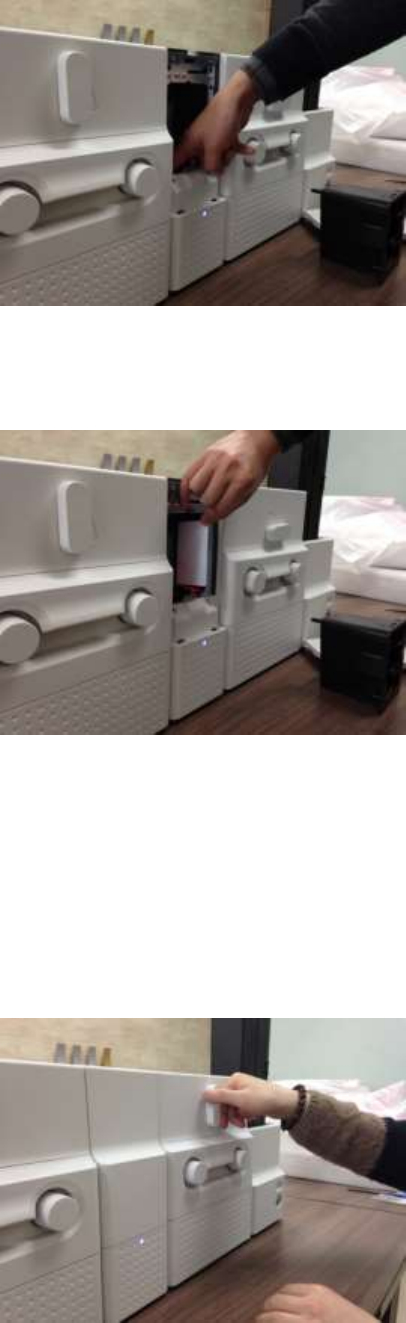
82
Figure 119 Card jam in Flipper 3
C. Card jam in Flipper 3
To remove a jammed card, please turn the
rotating tray of Flipper until the vertical by
hand as Figure.
Figure 120 Card jam in Flipper 4
D. Card jam in Flipper 4
Please pull out a jammed card as Figure.
5.3.4 Card jam in Laminator
Figure 121 Card jam in Laminator 1
A. Card jam in Laminator 1
Please turn the film cartridge lock lever to the
clockwise 90 degrees as Figure.
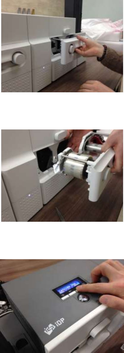
83
Figure 122 Card jam in Laminator 2
B. Card jam in Laminator 2
Please pull out the film cartridge as Figure.
Figure 123 Card jam in Laminator 3
C. Card jam in the Laminator 3
If laminating film is stuck to card or coiled on
rollers as Figure, the film cartridge may not be
pulled out easily. In this case, please cut the
laminating film or slowly pull out the film
cartridge while pressing the “” or “” button
on the control panel of Laminator little by little.
Figure 124 Card jam in Laminator 4
D. Card jam in Laminator 4
To remove a jammed card in laminator, please
press the “” button on the control panel of
Laminator until the jammed card is completely
ejected.
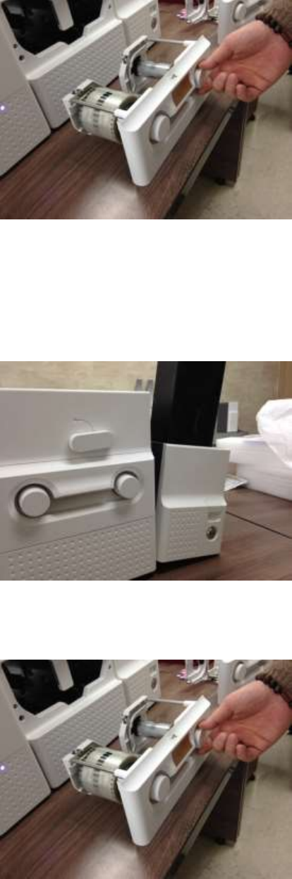
84
Figure 125 Card jam in Laminator 5
E. Card jam in Laminator 5
If laminating film is cut, please stick the cut
laminating film together by using a sticky tape
and then turn the dial on film cartridge until
unused laminating film is on take-up core.
5.3.5 Card jam in Output Hopper
Figure 126 Card jam in Output Hopper 1
A. Card jam in Output Hopper 1
Please separate Output Hopper as Figure after
disconnecting power adaptor and
communication cable at rear side.
Figure 127 Card jam in Output Hopper 2
B. Card jam in Output Hopper 2
If card is jammed on the card gate of Output
Hopper as Figure, please remove the jammed
card by pulling out.
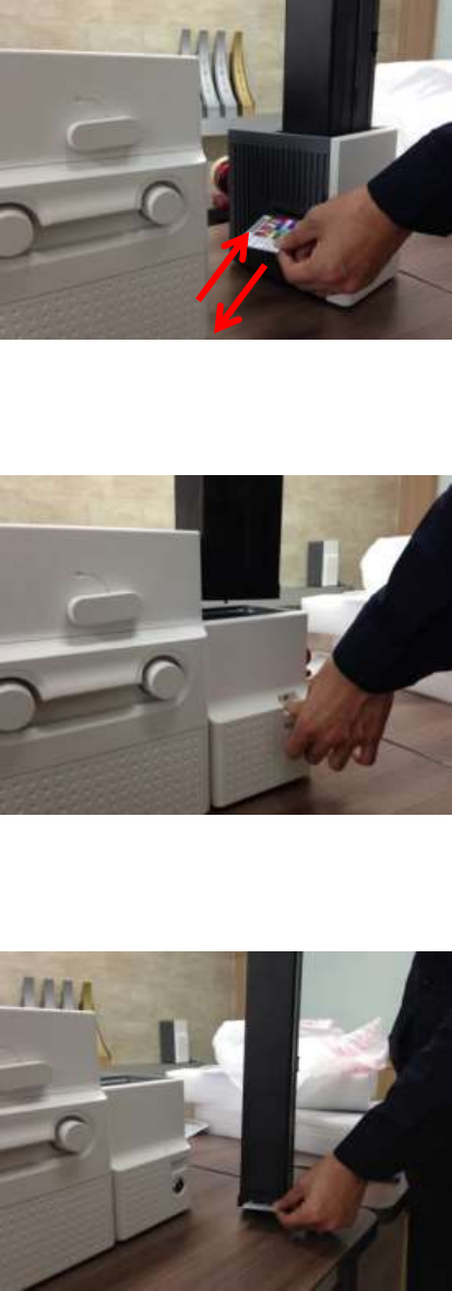
85
Figure 128 Card jam in Output Hopper 3
C. Card jam in Output Hopper 3
If card is not on the card gate of Output
Hopper but card cartridge can’t be pulled up,
please push in and pull out a new card as
Figure.
Figure 129 Card jam in Output Hopper 4
D. Card jam in Output Hopper 4
Please pull up card cartridge while pushing the
cartridge release button as Figure.
Figure 130 Card jam in Output Hopper 5
E. Card jam in Output Hopper 5
If card is jammed at the gate of card cartridge
as Figure, please remove the jammed card by
pulling out.
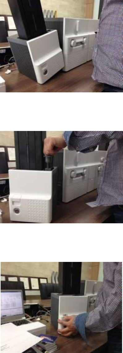
86
5.4 Cleaning
5.4.1 Input Hopper cleaning
Figure 131 Input Hopper cleaning 1
A. Input Hopper cleaning 1
Please separate Input Hopper as Figure after
disconnecting power adaptor and
communication cable at rear side.
Figure 132 Input Hopper cleaning 2
B. Input Hopper cleaning 2
Please remove the disposable cleaning roller
holder in Input Hopper as Figure.
Figure 133 Input Hopper cleaning 3
C. Input Hopper cleaning 3
Please pull up the card cartridge while pushing
the cartridge release button as Figure.
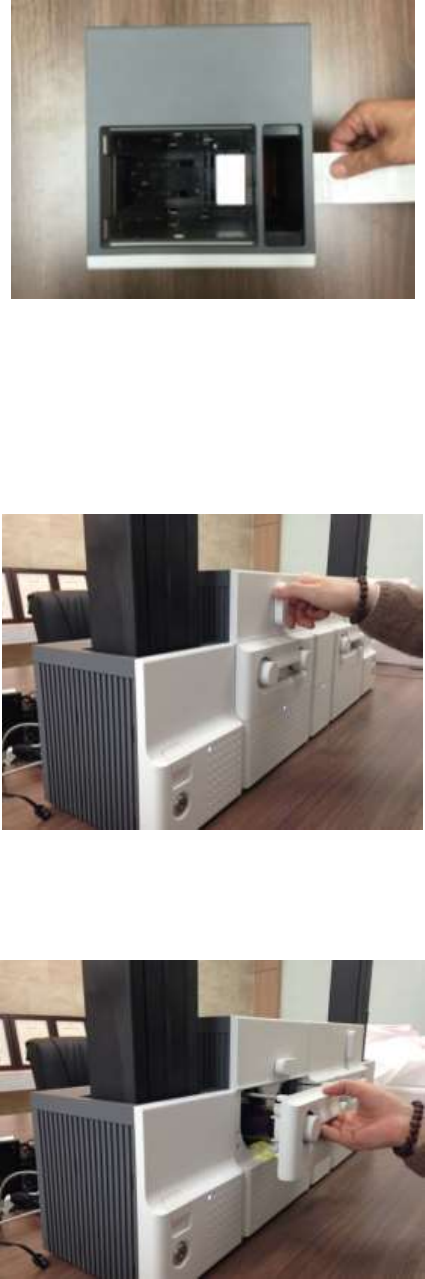
87
Figure 134 Input Hopper cleaning 4
D. Input Hopper cleaning 4
Please push a cleaning card into the card gate
of Input Hopper as Figure and clean rollers by
pushing in and pulling out the cleaning card
slowly and repeatedly.
5.4.2 Printer cleaning
Figure 135 Printer cleaning 1
A. Printer cleaning 1
Please turn the ribbon cartridge lock lever to
the clockwise 90 degrees as Figure.
Figure 136 Printer cleaning 2
B. Printer cleaning 2
Please pull out the ribbon cartridge as Figure.
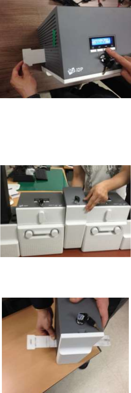
88
Figure 137 Printer cleaning 3
C. Printer cleaning 3
Please push a cleaning card in Printer while
pressing the “” button on the control panel
of Printer for 30 seconds as Figure.
After cleaning, please press the “” button to
remove the cleaning card.
5.4.3 Flipper cleaning
Figure 138 Flipper cleaning 1
A. Flipper cleaning 1
Please separate Flipper as Figure after
disconnecting power adaptor and
communication cable at rear side.
Figure 139 Flipper cleaning 2
B. Flipper cleaning 2
Please push a cleaning card into the card gate
of Flipper until the cleaning card is shown at
the other side as Figure and clean rollers by
pushing in and pulling out the cleaning card
slowly and repeatedly
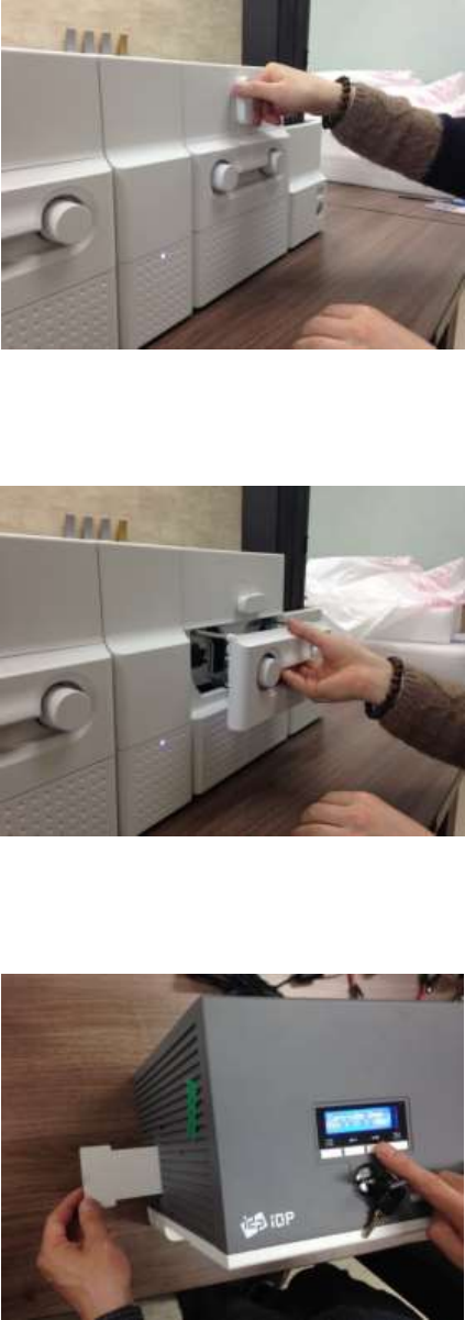
89
5.4.4 Laminator cleaning
Figure 140 Laminator cleaning 1
A. Laminator cleaning 1
Please turn the film cartridge lock lever to the
clockwise 90 degrees as Figure.
Figure 141 Laminator cleaning 2
B. Laminator cleaning 2
Please pull out the film cartridge as Figure.
Figure 142 Laminator cleaning 3
C. Laminator cleaning 3
Please push a cleaning card in Laminator while
pressing the “” button on the control panel
of Laminator for 30 seconds as Figure.
After cleaning, please press the “” button to
remove the cleaning card.
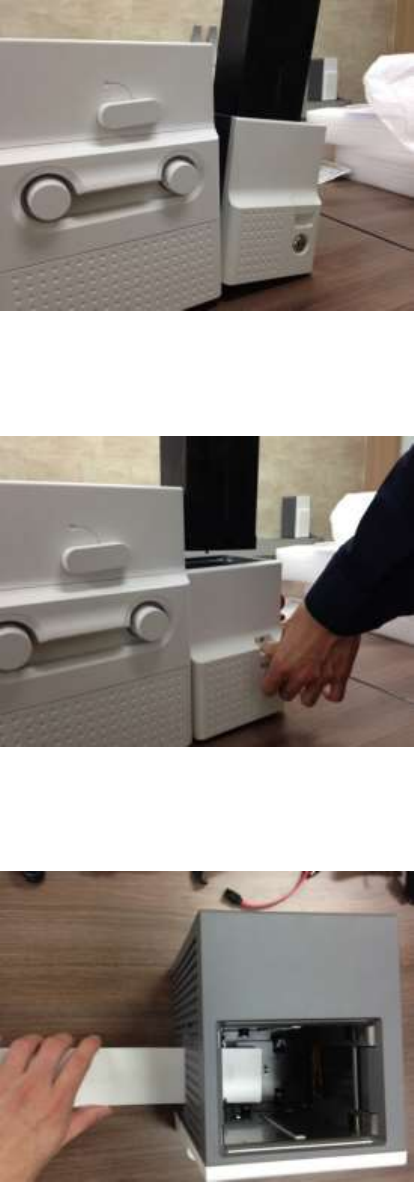
90
5.4.5 Output Hopper cleaning
Figure 143 Output Hopper cleaning 1
A. Output Hopper cleaning 1
Please separate Output Hopper as Figure after
disconnecting power adaptor and
communication cable at rear side.
Figure 144 Output Hopper cleaning 2
B. Output Hopper cleaning 2
Please pull up the card cartridge while pushing
the cartridge release button as Figure.
Figure 145 Output Hopper cleaning 3
C. Output Hopper cleaning 3
Please push a cleaning card into the card gate
of Output Hopper as Figure and clean rollers
by pushing in and pulling out the cleaning card
slowly and repeatedly.
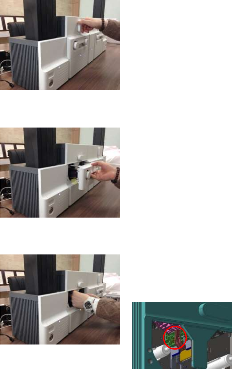
91
5.5 TPH (Thermal Print Head) replacement
Figure 146 TPH replacement 1
A. TPH replacement 1
Please turn the ribbon cartridge lock lever of
Printer to the clockwise 90 degrees as Figure.
Figure 147 TPH replacement 2
B. TPH replacement 2
Please pull out the ribbon cartridge as Figure.
Figure 148 TPH replacement 3
C. TPH replacement 3
Please detach the print head while pressing the
print head detaching button as Figure.
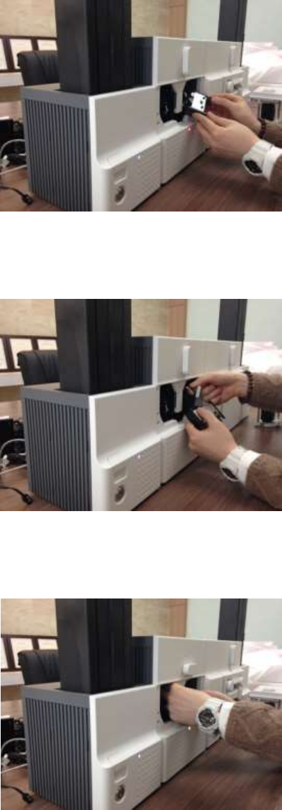
92
Figure 149 TPH replacement 4
D. TPH replacement 4
Please pull the detached print head out of
Printer while turning the ribbon cartridge lock
lever to the counterclockwise 90 degrees as
Figure.
Figure 150 TPH replacement 5
E. TPH replacement 5
Please disconnect the print head cable from the
detached print head as Figure and then
connect the print head cable to a new print
head.
Figure 151 TPH replacement 6
F. TPH replacement 6
Please install the new print head into Printer
while turning the ribbon cartridge lock lever to
the clockwise 90 degrees as Figure.
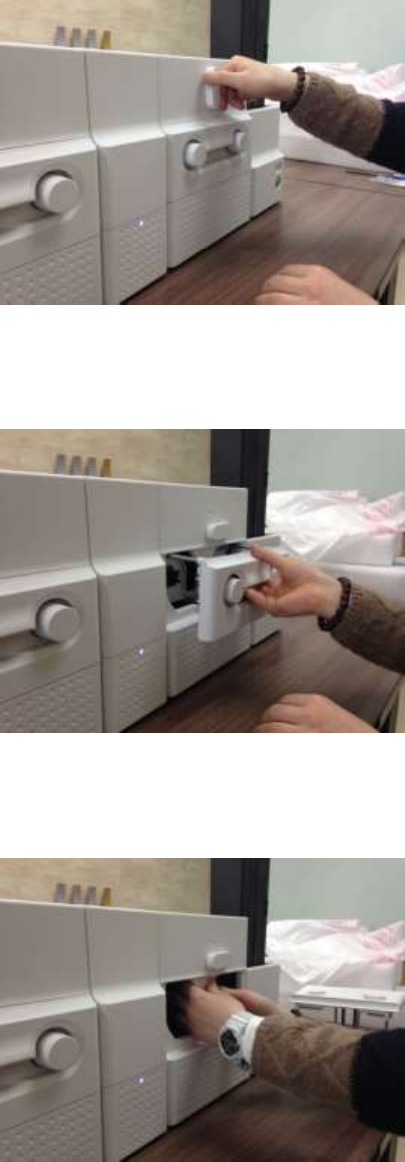
93
5.6 Laminator Head replacement
Figure 152 Laminator Head replacement 1
A. Laminator Head replacement 1
Please turn the film cartridge lock lever to the
clockwise 90 degrees as Figure.
Figure 153 Laminator Head replacement 2
B. Laminator Head replacement 2
Please pull out the film cartridge as figure.
Figure 154 Laminator Head replacement 3
C. Laminator Head replacement 3
Please detach the laminate head while pressing
the laminate head detaching button as Figure.
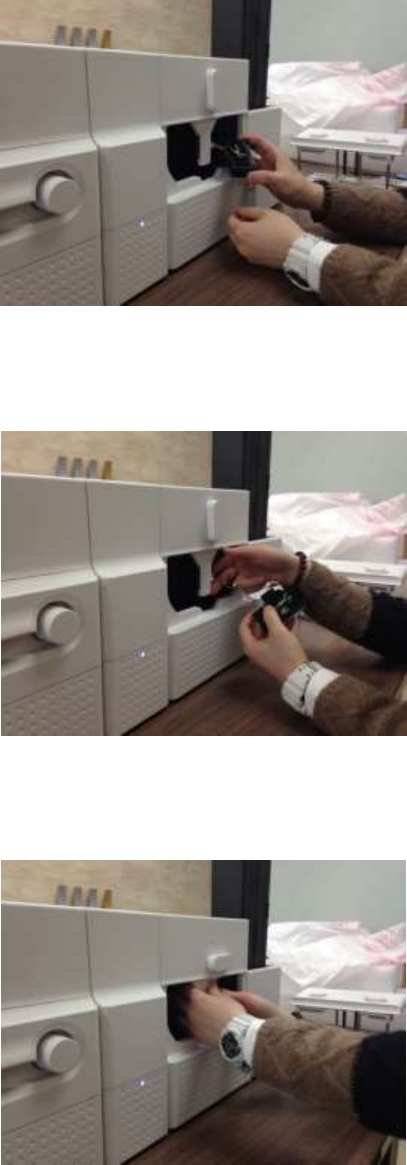
94
Figure 155 Laminator Head replacement 4
D. Laminator Head replacement 4
Please pull the detached laminate head out of
Laminator while turning the film cartridge lock
lever to the counterclockwise 90 degrees as
Figure.
Figure 156 Laminator Head replacement 5
E. Laminator Head replacement 5
Please disconnect 2 head cables from the
detached laminate head as Figure and then
connect the laminate head cables to a new
laminate head.
Figure 157 Laminator Head replacement 6
F. Laminator Head replacement 6
Please install the new laminate head into
Laminator while turning the film cartridge lock
lever to the clockwise 90 degrees as Figure.

95
6. SMART-70 Specifications
6.1 SMART-70 Input Hopper
Capacity
Card
Max. 500 cards
Feeding
Automatic
Card
Size
ISO CR80 (54mm x 86mm / 2.12” x 3.38”)
Thickness
0.38mm (15mil), 1.2mm (47mil)
Type
PVC, Composite PVC, PET
Sensor
Residual Q’ty Sensor
Near Empty & Empty
Detection Sensor
Cartridge Mount Status Detectable
System
Communication
RS-485, RS-232C
Power Supply(Adapter)
DC 24V, 2A
Temp. / Humidity
15~35℃ / 35~70%
Security
Physical Lock
Cartridge
Station Itself
Kensington Lock
Dimensions
Millimeter
170 (W) x 204 (L) x 548 (H)
Inch
6.7 (W) x 8.0 (L) x 21.6 (H)
Weight
Kg/lbs.
Approx. 3.7 kg / 8.2 lbs.
6.2 SMART-70 Encoding Station
Encoding Sensor
Magnetic
ISO 7811 (Track I, II, III Read/Write, HiCo/LoCo), JIS II
Contact
ISO 7816 (ID-1)
Contactless
MIFARE, ISO 1443(Type A/B), ISO 15693, DEFIRE, iCLASS
Barcode Reader
1D & 2D Barcode Reader (Front/Back)
System
Communication
USB, RS-232C
Power Supply
Free Voltage (AC100 / 220V, 50~60Hz)
Power Supply(Adapter)
DC 24V, 2A
Temp. / Humidity
15~35℃ / 35~70%
Security
Physical Lock
Encoding Station
Station Itself
Kensington Lock
Dimensions
Millimeter
240 (W) x 214 (L) x 305 (H)
Inch
9.5 (W) x 8.4 (L) x 12 (H)
Weight
Kg/lbs.
TBD

96
6.3 SMART-70 Printer
Printing
Print Type
Direct Dye-Sublimation
Print Area
Edge to Edge
Resolution
300dpi
Card
Card Feeding
Automatic
Card Size
ISO CR80 (54mm x 86mm / 2.12” x 3.38”)
Card Thickness
0.38mm (15mil), 1.2mm (47mil)
Card Type
PVC, Composite PVC, PET
Print Speed
Monochrome
3.6 sec./card (1,000 cards/hour)
YMCKO
18 sec./card (200 cards/hour),
Max. 16 sec./card (225 card/hour)
YMCKOK
24 sec./card (150 cards/hour),
Max. 22 sec./card (164 cards/hour)
Capacity
Input Hopper: Card
500 cards
Output Hopper: Card
Stacker: 100 cards/ *Optional Output Hopper: 500 cards
System
Memory
64MB RAM
Interface
2 Line LCD / 4 Buttons / 1 LED Indicator
Supported Platforms
Microsoft Windows 2000/ 2003/ XP/ Vista/ 7/ 8,
Max OS, Linux
Communication
USB(Device, Host), Ethernet, RS-485
Power Supply(Adapter)
DC 24V, 2A
Temp. / Humidity
15~35℃ / 35~70%
Security
Physical Lock
Print ribbon
S/W
PC authentication, Password authentication
Station Itself
Kensington Lock
Dimensions
Millimeter
240 (W) x 214 (L) x 305 (H)
Inch
9.5 (W) x 8.4 (L) x 12 (H)
Weight
Kg/lbs.
Approx. 6.3 kg / 13.9 lbs.

97
6.4 SMART-70 Flipper
System
Communication
RS-485
Power Supply(Adapter)
DC 24V, 2A
Temp. / Humidity
15~35℃ / 35~70%
Security
Physical Lock
Cards
Station Itself
Kensington Lock
Dimensions
Millimeter
110 (W) x 204 (L) x 305 (H)
Inch
4.3 (W) x 8.0 (L) x 12 (H)
Weight
Kg/lbs.
Approx. 2.8 kg / 6.2 lbs.
Error Card Bin
Ejection device for faulty card is equipped inside Flipper
(Max. 30 card.)
6.5 SMART-70 Laminator
Laminating
Type
Direct Heating Lamination
Speed
14 sec./card (Single-sided Laminating)
Laminating Film
Type
Clear, Holographic
Thickness
0.6mil, 1.0mil
Capacity
500 cards/Roll
System
Interface
2 Line LCD / 4 Buttons / 1 LED Indicator
Communication
RS-485, RS-232C, USB(디버그용)
Power Supply(Adapter)
DC 24V, 2A
Temp. / Humidity
15~35℃ / 35~70%
Security
Physical Lock
Laminating Film
Station Itself
Kensington Lock
Dimensions
Millimeter
240 (W) x 214 (L) x 305 (H)
Inch
9.5 (W) x 8.4 (L) x 12 (H)
Weight
Kg/lbs.
Approx. 6.1 kg / 13.4 lbs.

98
6.6 SMART-70 Output Hopper
Capacity
Card
Max. 500 cards
Feeding
Automatic
Card
Size
ISO CR80 (54mm x 86mm / 2.12” x 3.38”)
Thickness
0.38mm (15mil), 1.2mm (47mil)
Type
PVC, Composite PVC, PET
Sensor
Residual Q’ty Sensor
Full Space
Detection Sensor
Cartridge Mount Status Detectable
System
Communication
RS-485, RS-232C
Power Supply(Adapter)
DC 24V, 2A
Temp. / Humidity
15~35℃ / 35~70%
Security
Physical Lock
Cartridge
Station Itself
Kensington Lock
Dimensions
Millimeter
149 (W) x 204 (L) x 548 (H)
Inch
5.9 (W) x 8.0 (L) x 21.6 (H)
Weight
Kg/lbs.
Approx. 3.5 kg / 7.6 lbs.
Specifications and availability may change without notice.
Office: Room 601, 50, Digital-ro 33-gil, Guro-gu, Seoul, 152-742, Korea
Tel: +82-2-6099-3700 Fax: +82-2-6099-3717 E-mail: sales@idp-corp.com