IDS GeoRadar s r l AR600V24H10 Ground Penetrating Radar User Manual Users manual
IDS GeoRadar Srl Ground Penetrating Radar Users manual
Users manual
Signature
Date
Prepared by
Fabio Giannino
Verified by
Davide Morandi
Approved by
Paolo Cioce
Authorized by
Alberto Bicci
MN/2016/011
Rev 1.0
Stream-C (AR600V24H10)
Massive array GPR data acquisition system
User manual

INDEX
IDS GeoRadar s.r.l. MN/2016/011 Rev 1.0 Draft 2/36
INDEX
INTRODUCTION .............................................................................................................................................................................................................................. 4 1
PURPOSE ............................................................................................................................................................................................................................... 4 1.1
APPLICATION FIELD............................................................................................................................................................................................................... 4 1.2
INTENDED READERSHIP ........................................................................................................................................................................................................ 4 1.3
HOW TO READ THE MANUAL ......................................................................................................................................................................................................... 5 2
MANUAL LAYOUT ................................................................................................................................................................................................................. 5 2.1
SYMBOLS ............................................................................................................................................................................................................................... 5 2.2
GLOSSARY & ACRONYMS ...................................................................................................................................................................................................... 5 2.3
DEFINITIONS ......................................................................................................................................................................................................................... 6 2.4
STREAM-C HARDWARE DESCRIPTION ............................................................................................................................................................................................ 7 3
General ................................................................................................................................................................................................................................. 7 3.1
Laptop ................................................................................................................................................................................................................................. 12 3.2
Battery ................................................................................................................................................................................................................................ 13 3.3
Battery charger ................................................................................................................................................................................................................... 14 3.4
Accessories ......................................................................................................................................................................................................................... 14 3.5
Assembly procedure ..................................................................................................................................................................................................................... 16 4
Unfold the radar main body ............................................................................................................................................................................................... 16 4.1
Connect the antenna .......................................................................................................................................................................................................... 18 4.2
Connect the battery ............................................................................................................................................................................................................ 20 4.3
Connect the laptop ............................................................................................................................................................................................................. 20 4.4
........................................................................................................................................................................................................................................................ 21

1 INTRODUCTION
IDS GeoRadar s.r.l. MN/2016/011 Rev 1.0 Draft 3/ 36
Connect the electric engine battery (optional) .................................................................................................................................................................. 21 4.5
Mounting the hauling kit (optional) ................................................................................................................................................................................... 22 4.6
Mounting the GPS pole support (optional) ........................................................................................................................................................................ 23 4.7
GPS requirements ......................................................................................................................................................................................................................... 23 5
Maintenance plan ......................................................................................................................................................................................................................... 23 6
Cleaning Information .......................................................................................................................................................................................................... 23 6.1
Battery Removal Information ............................................................................................................................................................................................. 24 6.2
Periodical Check ................................................................................................................................................................................................................. 24 6.3
IDS On-line assistance ................................................................................................................................................................................................................... 24 7
Download area ................................................................................................................................................................................................................... 24 7.1
Remote assistance using Webex Support Center ............................................................................................................................................................... 25 7.2
APPENDIX A Disclaimer ..................................................................................................................................................................................................................... 28
APPENDIX B Warranty ....................................................................................................................................................................................................................... 30
APPENDIX C Technical Specification ................................................................................................................................................................................................. 32
APPENDIX D recycling ........................................................................................................................................................................................................................ 33
APPENDIX E conformity to european regulation .............................................................................................................................................................................. 33
APPENDIX F IMPORTANT NOTICE FOR THE US CUSTOMER ............................................................................................................................................................. 34
APPENDIX G IMPORTANT NOTE FOR CANADIAN CUSTOMERS ......................................................................................................................................................... 35
APPENDIX H CONTACTS ..................................................................................................................................................................................................................... 36

APPENDIX A. Disclaimer
IDS GeoRadar s.r.l. MN/2016/011 Rev 1.0 Draft 4/ 36
INTRODUCTION 1
This document describes the Stream-C radar system, and it refers to the
concepts the user should learn before initiating the utilization of this
device. Therefore it is recommended to carefully reading the entire
document before starting the system.
This manual contains a complete description of the Stream-C radar system,
detailing the assembly procedure, and the general operating procedures of
the system.
PURPOSE 1.1
Reading this document will provide all the necessary knowledge to install
and maintain the Stream-C. It illustrates a step by step procedure to install
the system, information for a safe utilization of the system and instructions
for its general maintenance.
APPLICATION FIELD 1.2
This system is dedicated to underground utilities localization and mapping
and it is used for applications in the civil engineering field.
INTENDED READERSHIP 1.3
The intended reader of this manual should be the technician in charge of
using the system that has undergone the IDS training for Stream-C.
APPENDIX A. Disclaimer
IDS GeoRadar s.r.l. MN/2016/011 Rev 1.0 Draft 5/ 36
HOW TO READ THE MANUAL 2
MANUAL LAYOUT 2.1
This manual is composed of several parts. After an Introduction, the first
part describes the device and its components, with the explanation of the
main features.
The second part shows the procedure to install the device and how to
configure it correctly (Assembly Procedure).
Then, a description of the main feature of the GNSS to be used in
conjunction with the system, are described.
Eventually, the maintenance plan, and additional information are
illustrated.
SYMBOLS 2.2
This manual contains the following symbols with related meanings:
possible hazardous situation
To keep on mind
To keep on mind
GLOSSARY & ACRONYMS 2.3
DAD: Digital Antenna Device
RADAR: RAdio Detection And Ranging
USB: Universal Serial Bus
GPR: Ground Penetrating Radar
HDOP: Horizontal Dilution Of Precision
RTK: Real Time Kinematic
LAN: Local Area Network
GPS: Global Positioning System
GNSS: Global Navigation Satellite System
AC: Alternate Current
NMEA: National Marine Electronics Association
CORS: Continuously Operating Reference Station
UHF: Ultra High Frequency
GSM: Global System for Mobile communications
WMS: Web Map Service
DXF: Digital eXchange Format
KML: Keyhole Markup Language
GIS: Geographic Information System

APPENDIX A. Disclaimer
IDS GeoRadar s.r.l. MN/2016/011 Rev 1.0 Draft 6/ 36
To keep on mind
DEFINITIONS 2.4
Raw data: unprocessed data obtained during a field survey.
Maps: graphics showing the change in received radar signal with respect to
the scanning direction.
Survey: the name given to a collection of acquisitions, which together cover
all the areas of a large investigation: typically an entire town or a large
urban area.
Scan: a single movement of the antenna trolley from the beginning to the
end of a pre-established path.
Setup: initialization of a piece of equipment or a software process.
Encoder: a distance measurement device which constantly signals the
distance travelled from the start of the scan back to the Control Unit .
Transmitter: part of the antenna dedicated to emitting the radar signals.
Receiver: part of the antenna dedicated to detecting the radar signals.
Utilities: the objects the Stream-C searches for, i.e. pipes supplying gas and
water, electricity cables, etc.
APPENDIX A. Disclaimer
IDS GeoRadar s.r.l. MN/2016/011 Rev 1.0 Draft 7/ 36
STREAM-C HARDWARE DESCRIPTION 3
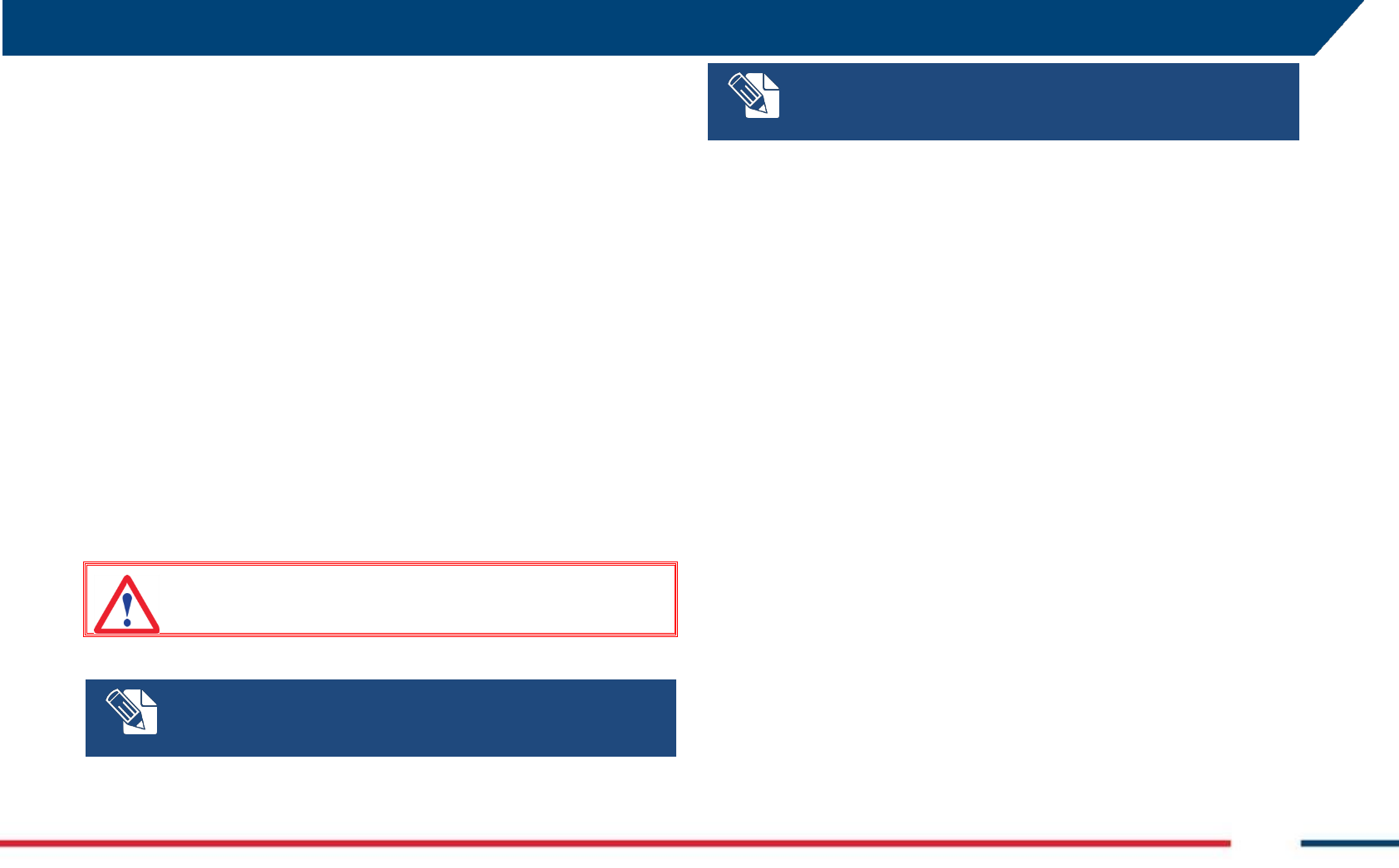
General 3.1
The Stream-C system is composed by the following parts:
Stream-C main body
Laptop (with One Vision data acquisition software)
Battery(s)
Battery charger
Accessories
o GPS support
o Hauling kit
o Electric motor kit
This chapter contains the description of the above listed parts.
The whole system is shown in Fig. 3.1 (actual picture), and Fig. 3.2 (Sketch).
Stream-C is available in two versions: one motor-assisted, and one
manually-operated. The first needs two extra-batteries (12V-24Ah) to be
operated with the motor (total weight of the system is 72 Kg), the latter
does not need any extra battery, except the one to power the Stream-C
(total weight of the system is 65 Kg).
Fig. 3.1 – The Stream-C
APPENDIX A. Disclaimer
IDS GeoRadar s.r.l. MN/2016/011 Rev 1.0 Draft 8/ 36
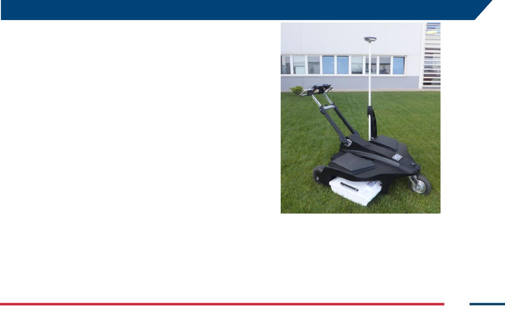
Fig. 3.2 – Sketch of the Stream-C and its main components
Stream-C main body 3.1.1
The main body of the system consists of a trolley with foldable handle, for
an easier storage and transportation; it includes the following parts:
Antenna
Control unit
Encoder
Handle
Wheels
Laptop support
Wheel Blockage system
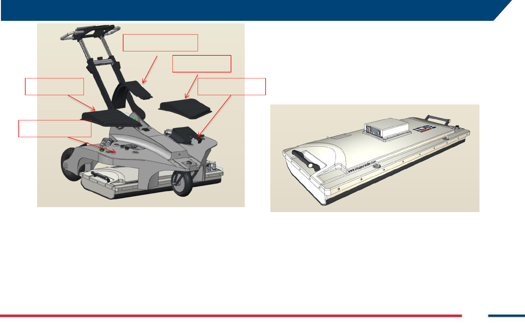
Antenna 3.1.2
The Stream-C System deploys an antenna with 34 channels (Fig. 3.3).
The antenna box is 120cm wide, 20cm high, and 57cm deep. Its weight is
20Kg, and its power consumption equals 60W.
Fig. 3.3 – Sketch of the Stream-C antenna
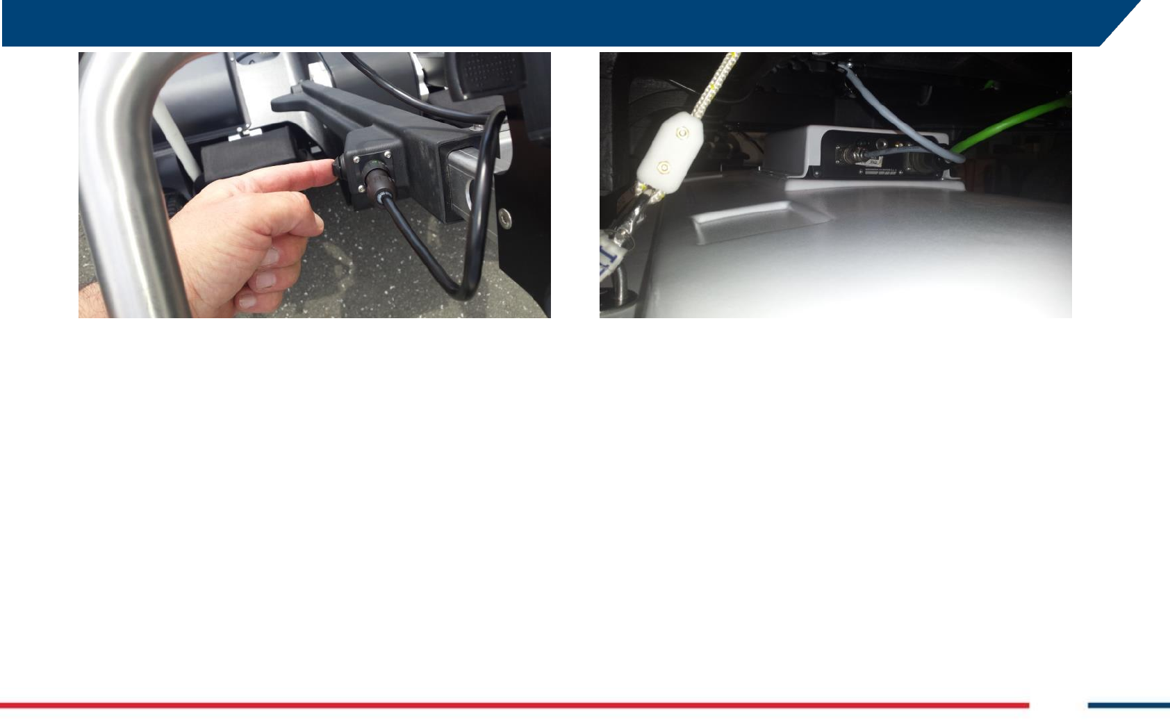
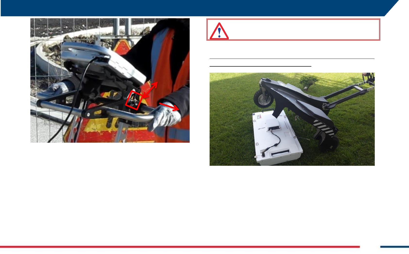
The antenna height can be adjusted (of about 5 cm) through an electric
command located at the left hand side of the rudder (Fig. 3.4).
Battery cover
Left Cover
Left Cover
Main Frame
Front Cover
APPENDIX A. Disclaimer
IDS GeoRadar s.r.l. MN/2016/011 Rev 1.0 Draft 9/ 36
Fig. 3.4 – The command to adjust the antenna height
Control unit 3.1.3
The Control Unit, or DAD, is the central part of the system because it
communicates with the antenna, the laptop and the encoder, making all
the systems work together.
The DAD is lodged on top of the antenna box and has a power button on
top of it to turn it on/off (Fig. 3.5).
The characteristics of the Control Unit are:
Voltage: 12 V +/- 10%
Environment feature: IP 65
Absorbed power: 8 W
Operating temperature: -10/+40 °C
Fig. 3.5 – DAD unit
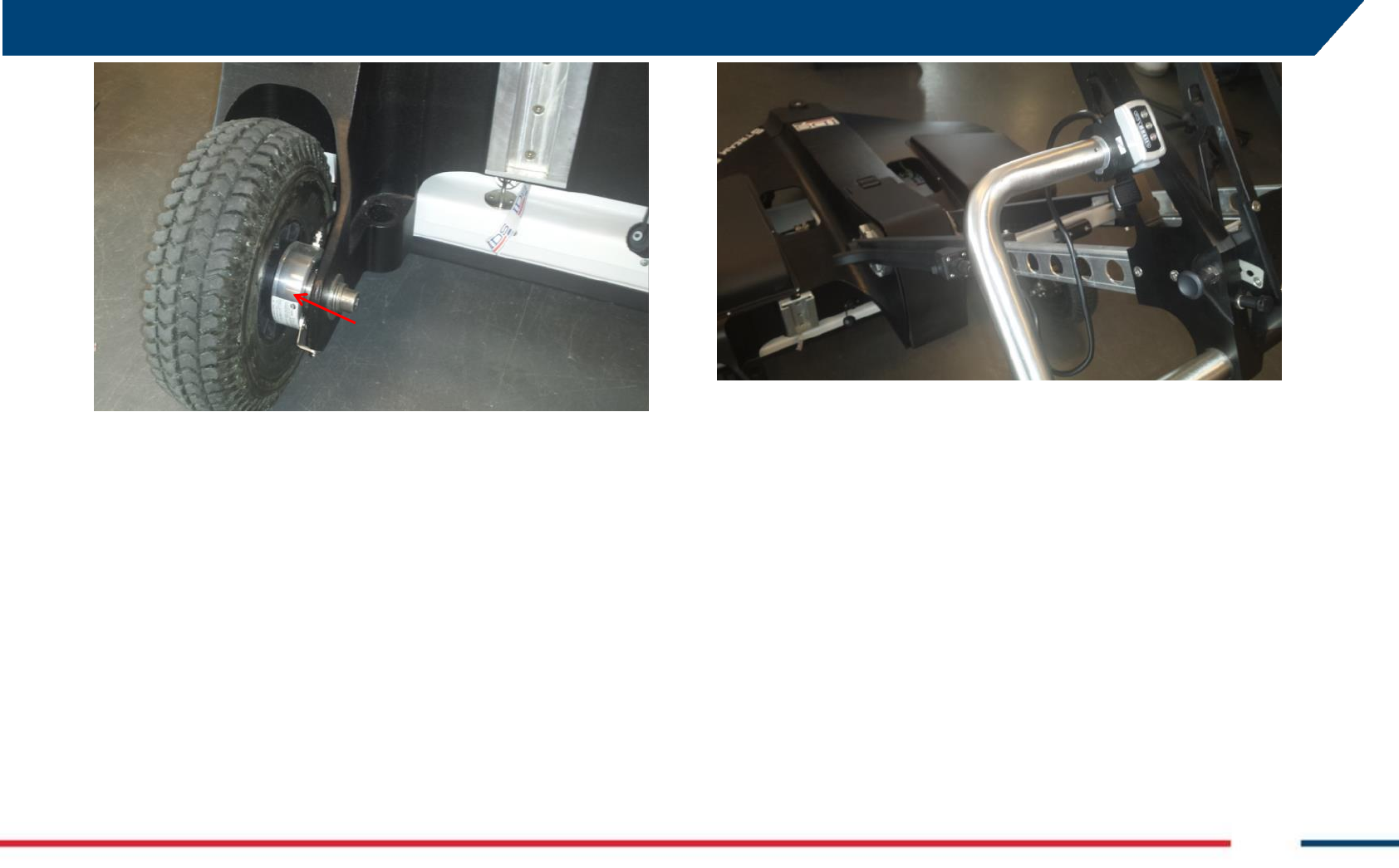
Encoder 3.1.4
The Stream-C employs one encoder for collecting distance data, and this is
positioned inside the rear left wheel (Fig. 3.6).
APPENDIX A. Disclaimer
IDS GeoRadar s.r.l. MN/2016/011 Rev 1.0 Draft 10/ 36
Fig. 3.6 – The encoder (red arrow)
Handle 3.1.5
The Stream-C handle is an ergonomic and adjustable bar (Fig. 3.7), whose
orientation can be adjusted both in height and inclination.
Fig. 3.7 – The Stream-C Handle
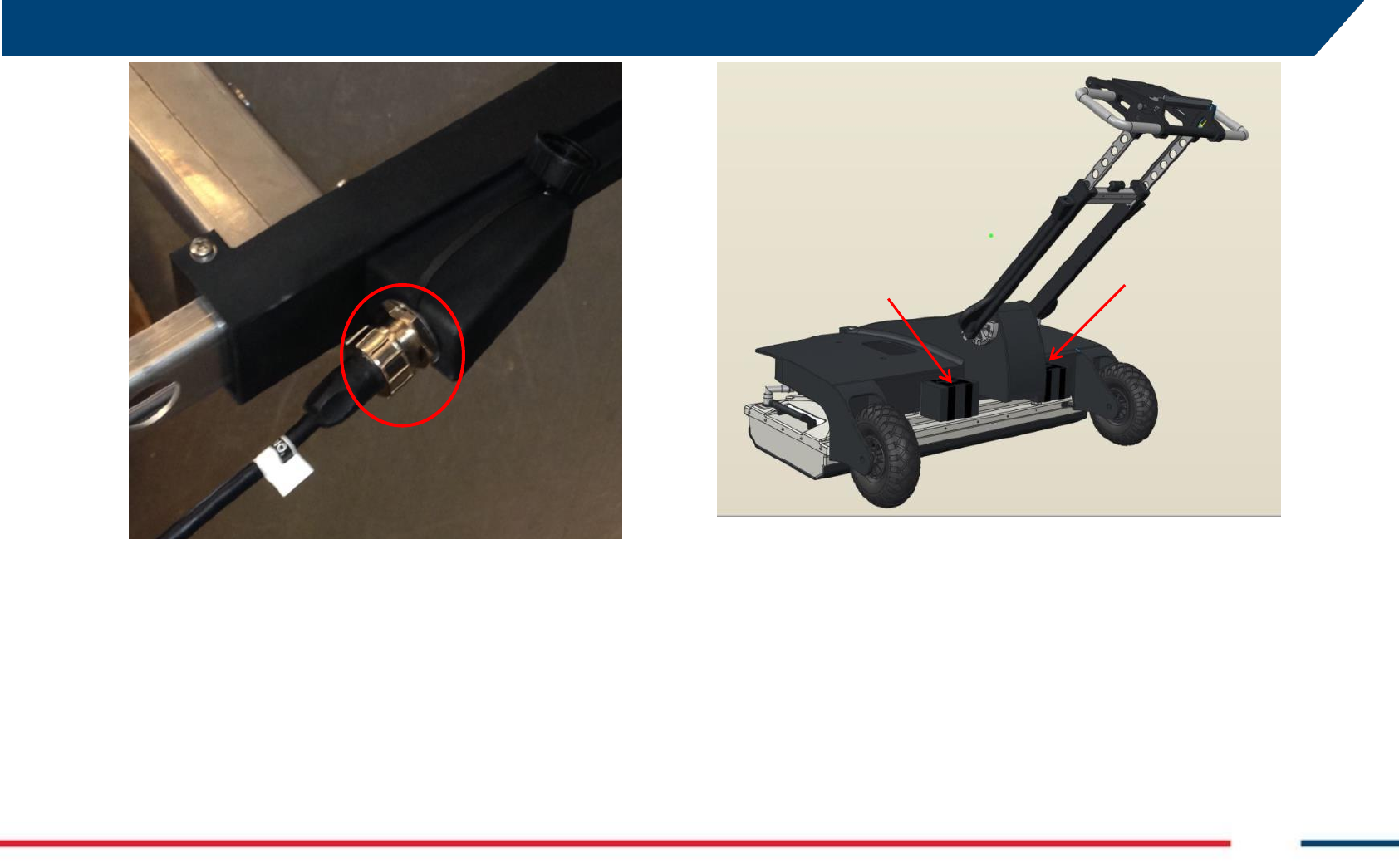
The Laptop support is mounted on top of the handle bar (see par. 3.1.7).
The Handle bar also contains the Ethernet cable that goes to the laptop
(Fig. 3.8).
APPENDIX A. Disclaimer
IDS GeoRadar s.r.l. MN/2016/011 Rev 1.0 Draft 11/ 36
Fig. 3.8 – Ethernet cable plug on the handle (red circle)
Wheels 3.1.6
The Stream-C is a three wheeled system and comes into two versions: one
is only manually operated and one is electric motor-assisted (optional),
powered by two batteries lodged in the rear part of the Stream –C main
body (Fig. 3.9).
The manually operated version, can be upgraded into a motorized one.
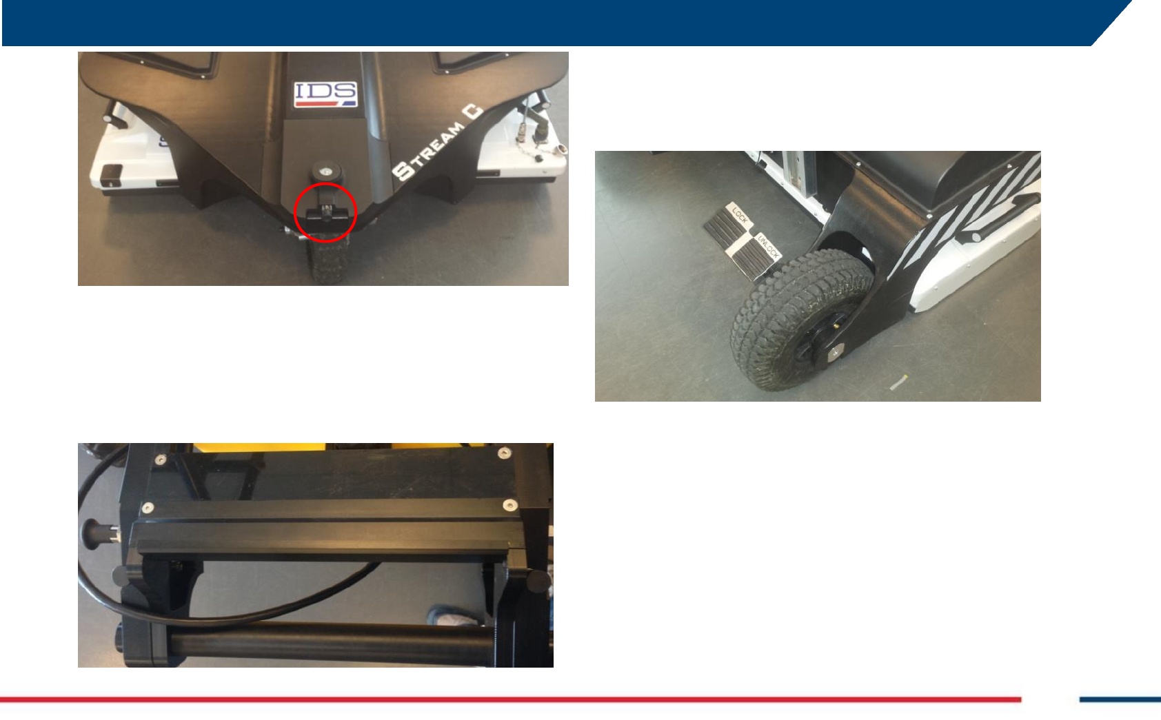
The front wheel is pivoting, to facilitate the manoeuvre, and can be blocked
in straight position, by a pull system located in the front part of the Stream-
C frame (Fig. 3.10).
Fig. 3.9 – The position of the batteries powering the electric motor to operate the system
(red arrows)
APPENDIX A. Disclaimer
IDS GeoRadar s.r.l. MN/2016/011 Rev 1.0 Draft 12/ 36
Fig. 3.10 – Pivoting wheel blocking gear (red circle)
Laptop support 3.1.7
The inclination of the Laptop support can be adjusted to achieve the best
viewing angle for the user (Fig. 3.11).
The support is designed to hold a laptop Panasonic CF-H2, but also a
different type of computer may be laid on top of it.
Fig. 3.11 – Laptop support
Wheel Blockage system 3.1.8
A system to lock/unlock the system is mounted on the rear right wheel of
the system to secure the stop position when the system is in non-operative
mode (Fig. 3.12).
Fig. 3.12 – Wheel Blockage system
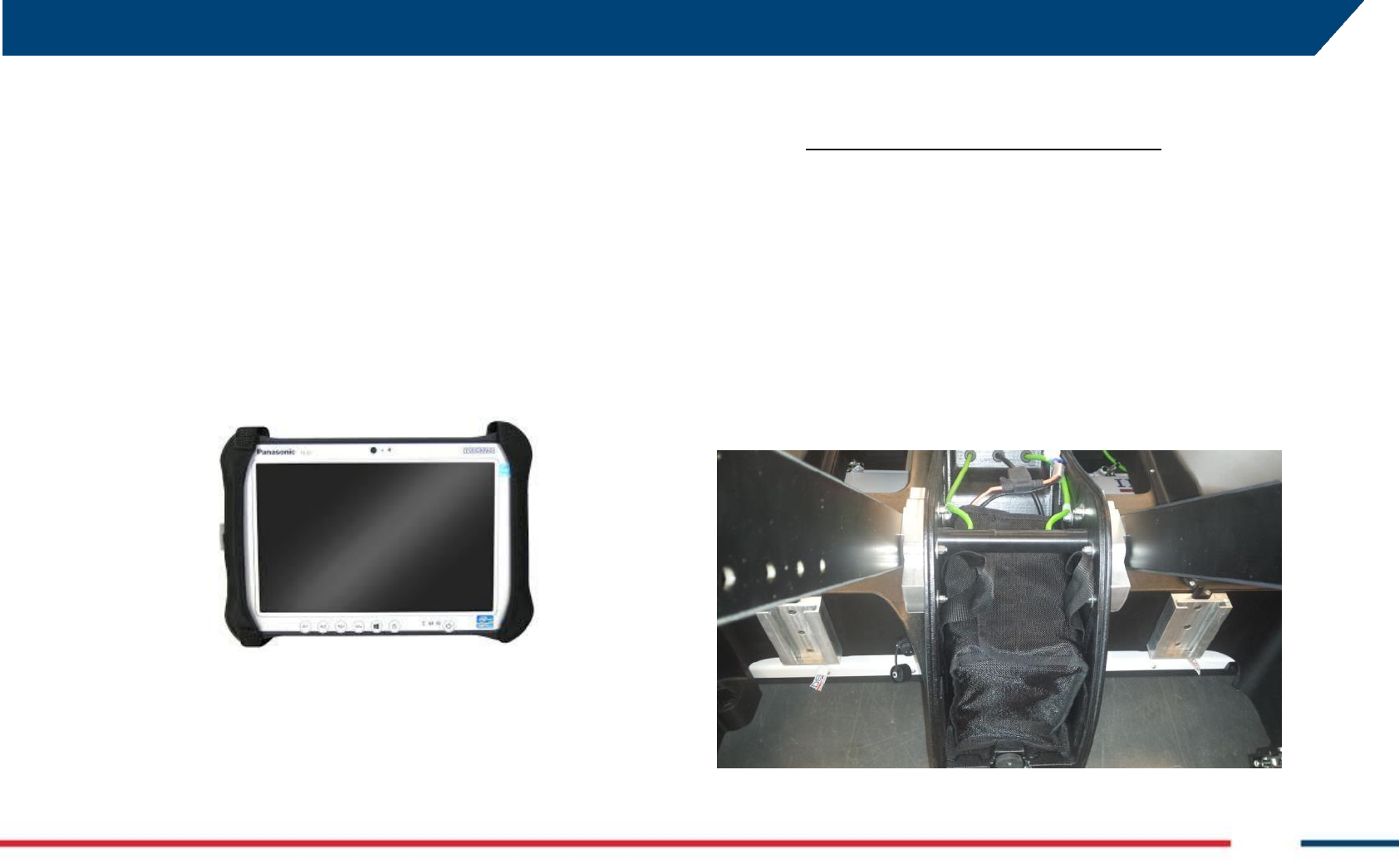
Laptop 3.2
The system can be provided with a laptop (see Fig. 3.13), with the software
already installed; however the user can operate Stream-C with any laptop
respecting the following minimum requirements:
Processor: i3 1.7 GHz
RAM: 1 GB
Graphic adapter compatible with Open GL 2 or newer
Operative system: Windows 7
Ethernet port
APPENDIX A. Disclaimer
IDS GeoRadar s.r.l. MN/2016/011 Rev 1.0 Draft 13/ 36
However, for an optimal performance we recommend the following
requirements:
Processor: i5 1.7 GHz
RAM: 2GB
Graphic adapter compatible with Open GL 2 or newer
Screen resolution: 1024 X 786
Operative System: Windows 7
Hard disk: 40 GB shock proof
Serial port RE 232 (only used with the GPS)
USB port
Ethernet port
Fig. 3.13 – Laptop for Stream-C
Prior to the software installation the user should be sure that the drivers of
the graphic adapter are updated to the latest version.
For example for Intel graphic adapter those steps can be followed:
1. Connect the laptop to internet (the user should set the IP
address to dynamic for this operation);
2. Open an internet browser and go to
http://www.intel.com/p/en_US/support/detect;
3. Install the updated drivers;
4. Change again the IP address to the original one.
Battery 3.3
The battery used by an Stream-C system provides power to the Control
Unit and, from there, to the Antenna, the Encoder, the antenna up/down
system, and the hauling system remote control (optional), if present; the
battery does not provide power to the laptop or the GPS, if present.
The Stream-C battery is a 12 V / 12 Ah rechargeable lead battery lodged in
the rear part of the system, between the arms of the handle at the
attachment with the main body (see Fig. 3.14).
Fig. 3.14 – Stream-C battery position
APPENDIX A. Disclaimer
IDS GeoRadar s.r.l. MN/2016/011 Rev 1.0 Draft 14/ 36
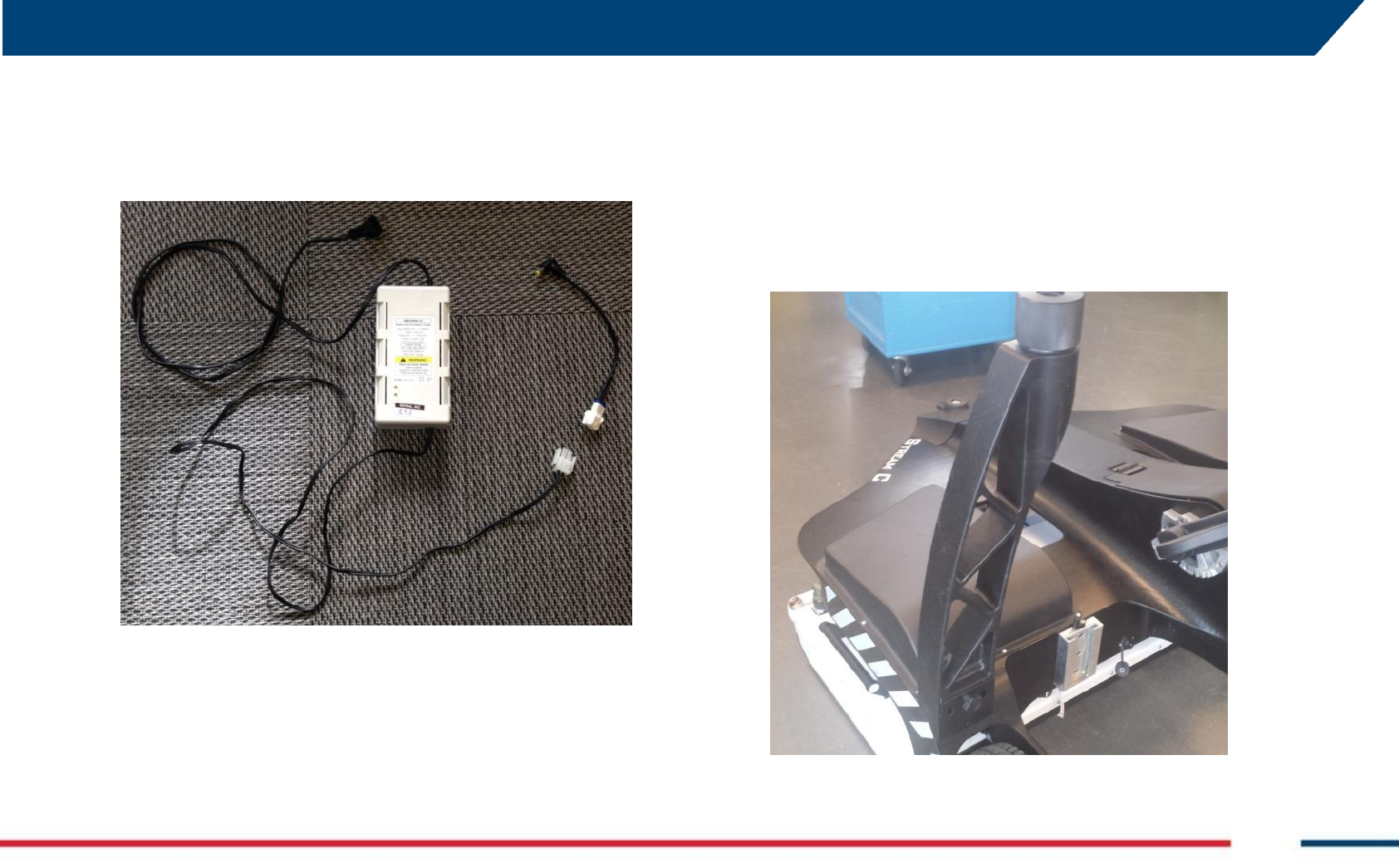
Battery charger 3.4
The battery charger is composed of two parts: a small cable to connect the
battery to the charger and the battery charger itself, to be connected to the
electricity mains at AC 110/220 (see Fig. 3.15).
Fig. 3.15 – Battery charger
The battery can be charged whilst connected to the system or after having
been removed. Note that, in either case, the radar cannot be turned on
during the battery charging.
Accessories 3.5
GPS Support 3.5.1
The GPS support can be easily mounted on the radar main body (rear left
part) and holds the GPS pole (see Fig. 3.16).
Fig. 3.16 – GPS Support in the storage bag
APPENDIX A. Disclaimer
IDS GeoRadar s.r.l. MN/2016/011 Rev 1.0 Draft 15/ 36
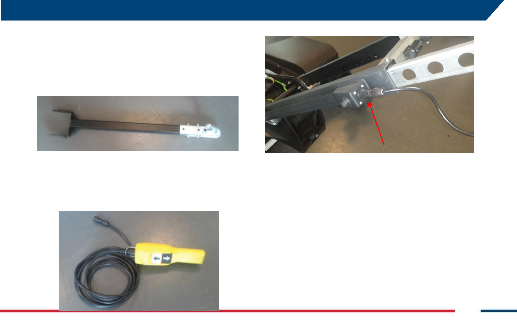
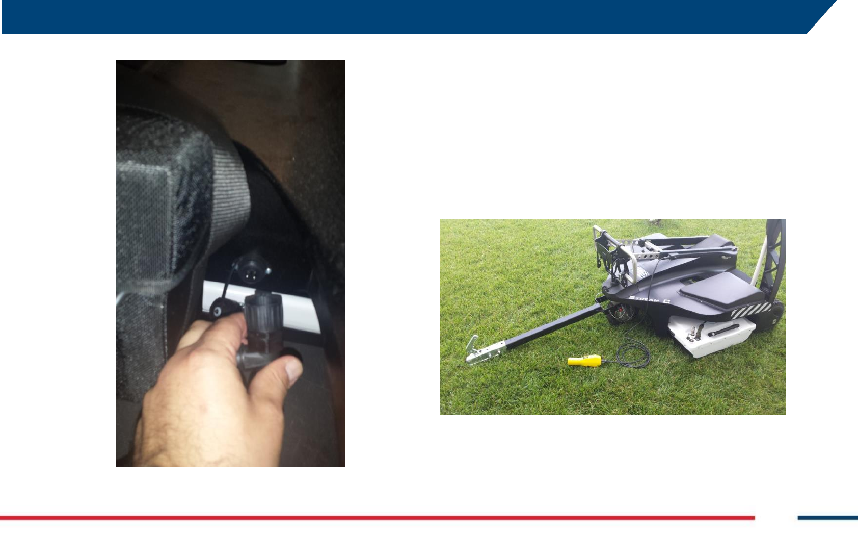
Hauling Kit 3.5.2
The Stream-C system can also be provided with an optional kit to pull the
system by a vehicle (Fig. 3.17).
Fig. 3.17 – The Hauling kit
In this case, the handle is maintained in the folded position, and a remote
control (Fig. 3.18) is connected to the handle (Fig. 3.19) to move the
antenna up and down.
Fig. 3.18 – The Antenna height remote control
Fig. 3.19 – The remote control connector to the handle (red arrow)
Electric motor kit 3.5.3
Stream-C offers the possibility (as an optional) to be operated by an
electric motor. The system, is embedded into the front pivoting wheel and
can be manoeuvred by a command, located on top the left side of the
handle (Fig. 3.20).

APPENDIX A. Disclaimer
IDS GeoRadar s.r.l. MN/2016/011 Rev 1.0 Draft 16/ 36
Fig. 3.20 – Electric Engine command
Assembly procedure 4
The procedure to assemble the Stream-C is very simple and can be
performed by one person.
To assemble the system follow these steps:
1. Unfolding the radar main body (Par. 4.1);
2. Connecting the antenna (Par. 4.2)
3. Connecting the battery (Par. 4.3)
4. Connecting the laptop (Par 4.4);
5. Connecting the Electric Engine battery (Optional, Par. 4.5);
6. Mounting the Hauling kit support (optional, Par. 4.6);
7. Mounting the GPS support (optional, Par. 4.7.
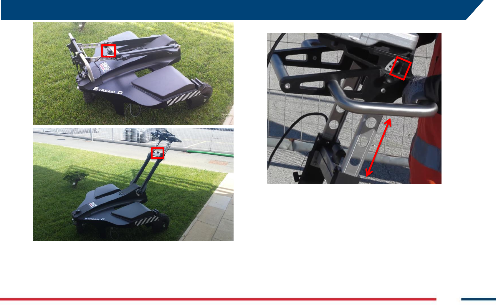
Unfold the radar main body 4.1
To unfold the Stream-C main body place it to on the ground, press the
central handle button and raise the rudder to the desired angle (Fig. 4.1).
APPENDIX A. Disclaimer
IDS GeoRadar s.r.l. MN/2016/011 Rev 1.0 Draft 17/ 36
Fig. 4.1 – Unfolding the Stream-C through the button into the red square
The user can also adjust the height of the handle bar and laptop support, by
using the two vertical buttons (red square) in the upper part of the rudder
(Fig. 4.2).
Fig. 4.2 – Handle bar and laptop support height regulation buttons
The inclination of the laptop support can be changed opening the two
horizontal locks (red squares) on its sides (Fig. 4.3).
APPENDIX A. Disclaimer
IDS GeoRadar s.r.l. MN/2016/011 Rev 1.0 Draft 18/ 36
Fig. 4.3 – Laptop support inclination regulation
Connect the antenna 4.2
To connect the antenna with the main body of the system, pull up the front
of the frame (Fig. 4.4), and lay it gently on top of the antenna, paying
attention not to damage any part of the connectors. Then, connect the
cables to the connectors on top of the antenna and the DAD, and lock the
hooks to the up/down system of the frame, as specified below.
possible hazardous situation
In performing this operating pay attention not to pinch fingers between the
main body of Stream-C, and the antenna body.
Fig. 4.4 – Raising the frame to connect the antenna
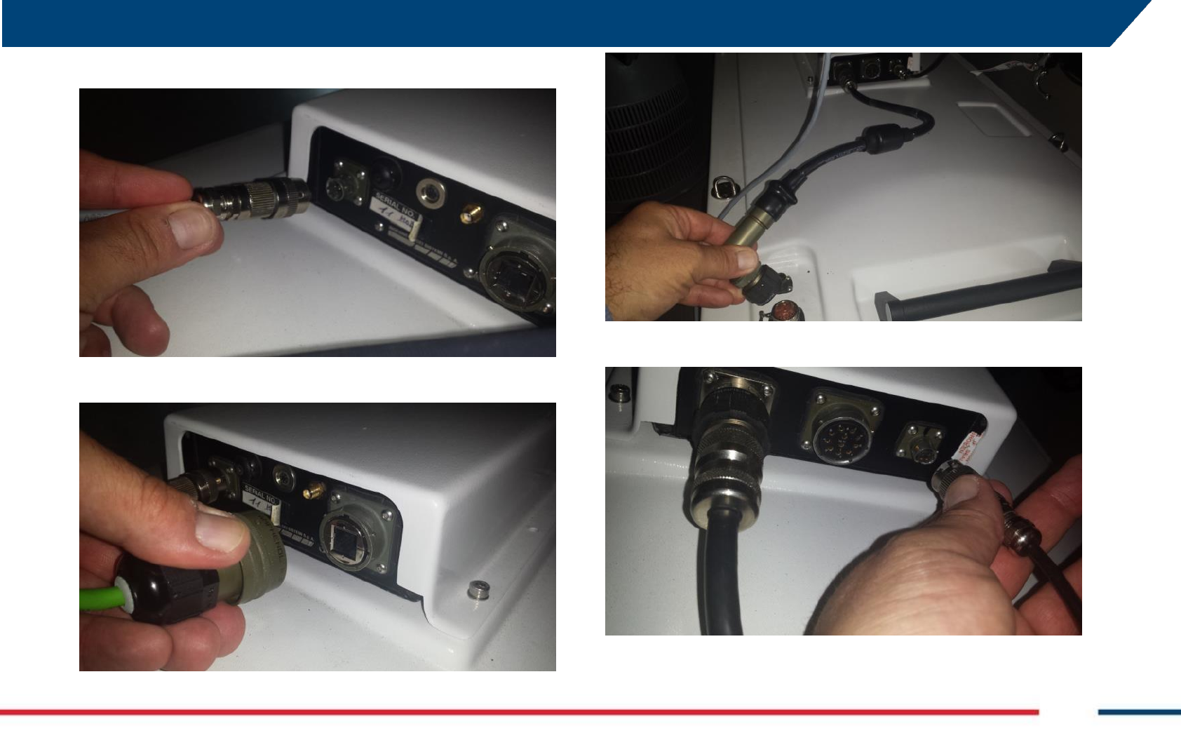
In particular, follow these steps:
1. Connect the battery cable between the frame and the DAD (),
2. Connect the LAN cable (),
3. Connect the antenna cable between the DAD and the antenna (),
4. Connect the wheel cable (),
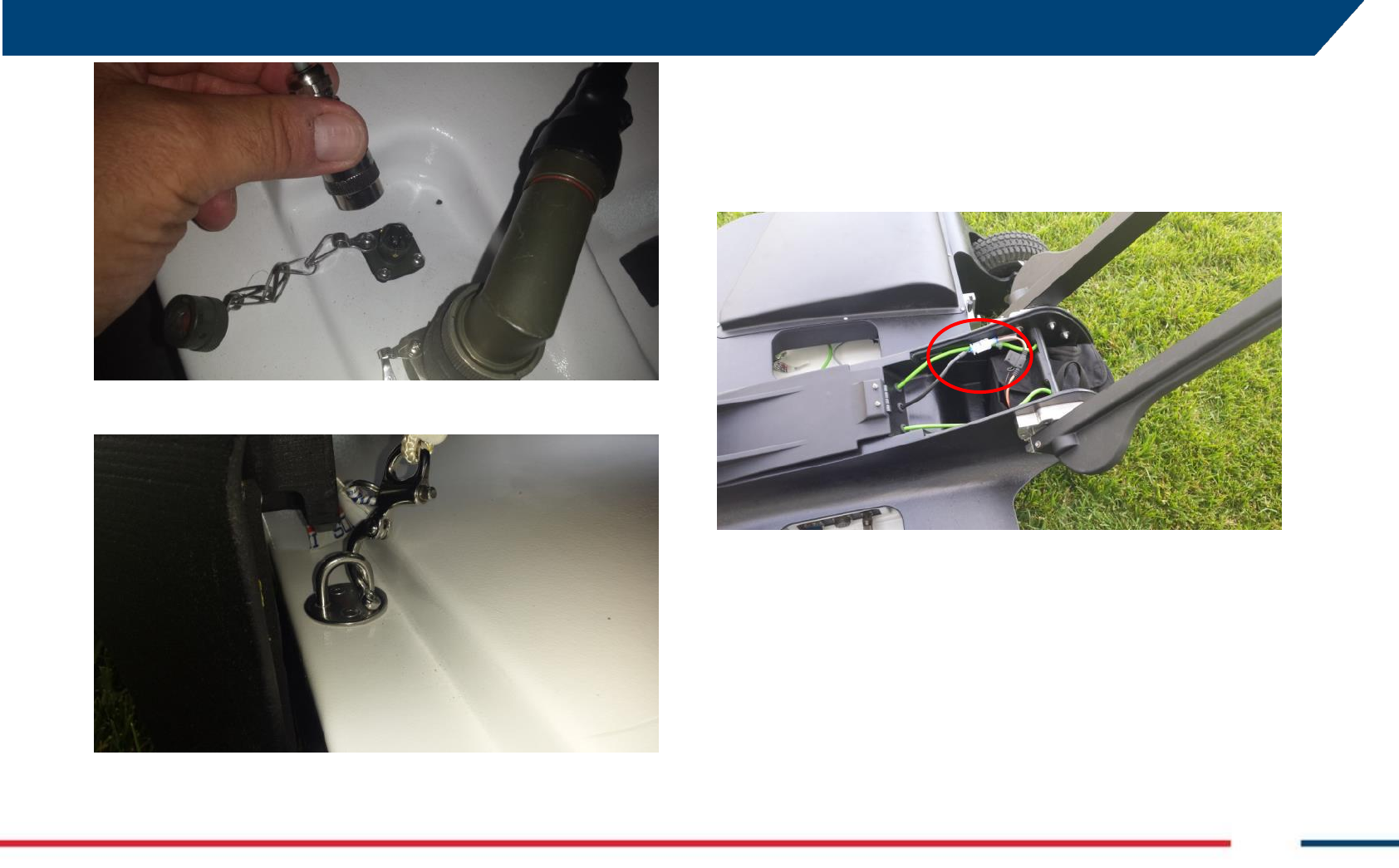
5. Connect the second power cable between the frame and the
antenna,
6. Connect the quick release to the four u-shaped hooks on top of the
antenna ().
APPENDIX A. Disclaimer
IDS GeoRadar s.r.l. MN/2016/011 Rev 1.0 Draft 19/ 36
Fig. 4.5 – Connecting the battery cable
Fig. 4.6 – Connecting the LAN cable
Fig. 4.7 – Connecting antenna cable
Fig. 4.8 – Connecting the wheel cable to the DAD
APPENDIX A. Disclaimer
IDS GeoRadar s.r.l. MN/2016/011 Rev 1.0 Draft 20/ 36
Fig. 4.9 – Connecting the second power cable to the antenna
Fig. 4.10 – Locking the antenna to the four quick release
Connect the battery 4.3
To connect the main battery, open from the rear toward the front of the
system, the battery housing cover between the two arms of the handle,
and then connect the male/female connectors between the battery and the
battery housing (Fig. 4.11).
Fig. 4.11 – Connecting the main battery (male/female connectors are in the red circle)
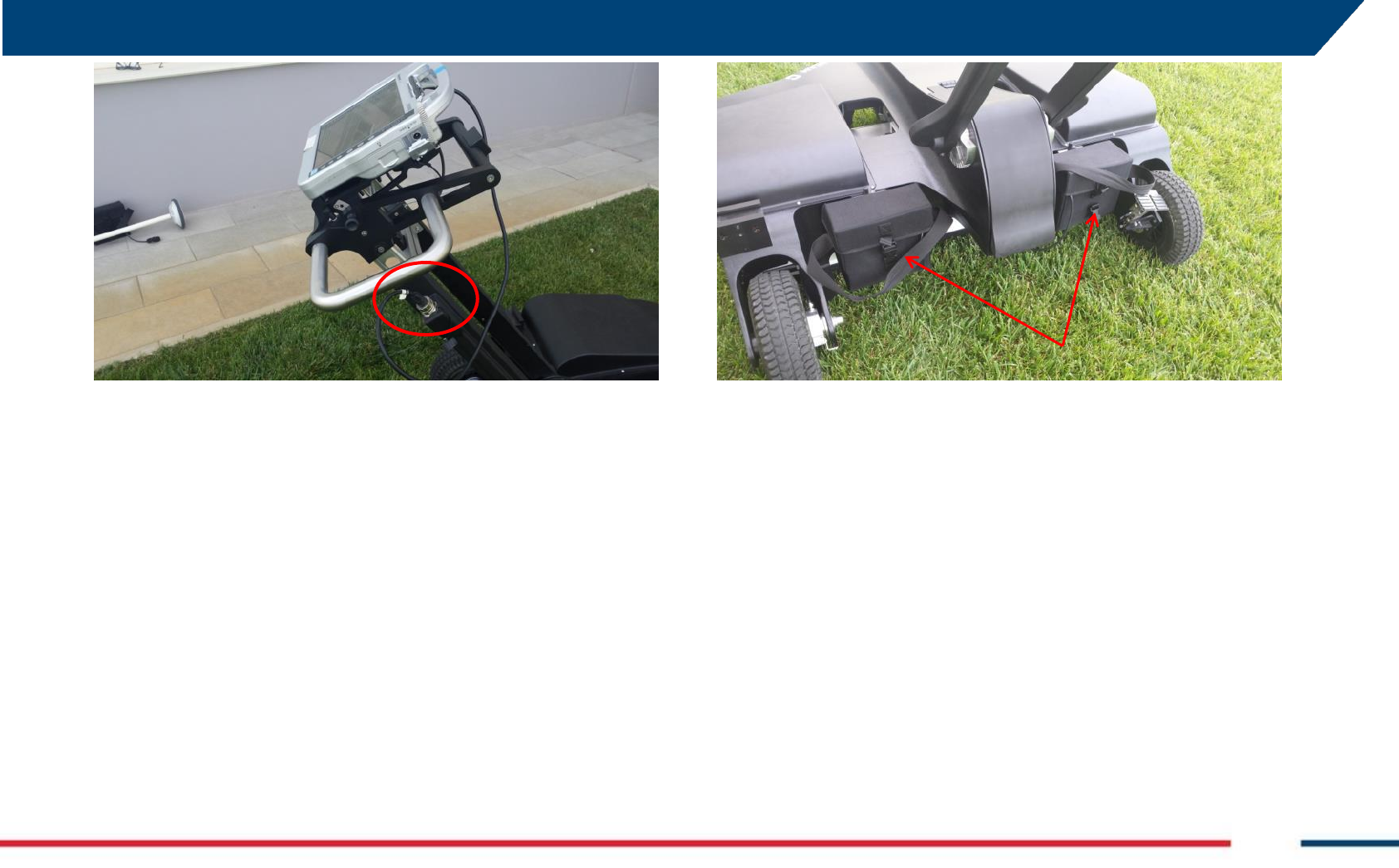
Connect the laptop 4.4
After laying the laptop on top of the laptop support, connect the laptop and
the system through the LAN cable starting from the right hand side of the
handle (Fig. 4.12).
APPENDIX A. Disclaimer
IDS GeoRadar s.r.l. MN/2016/011 Rev 1.0 Draft 21/ 36
Fig. 4.12 – connecting the laptop through the LAN cable (red circle)
Connect the electric engine battery (optional) 4.5
The batteries powering the electric engine moving the system, are housed
at the rear part of Stream-C (Fig. 4.13), and connected to it through two
connectors (Fig. 4.14).
To connect the batteries, just slide the metal part of the support bag of the
batteries from top to bottom of the frame.
Fig. 4.13 – c
APPENDIX A. Disclaimer
IDS GeoRadar s.r.l. MN/2016/011 Rev 1.0 Draft 22/ 36
onnecting the electric engine batteries (optional, red arrows)
Fig. 4.14 – connectors of the electric engine batteries
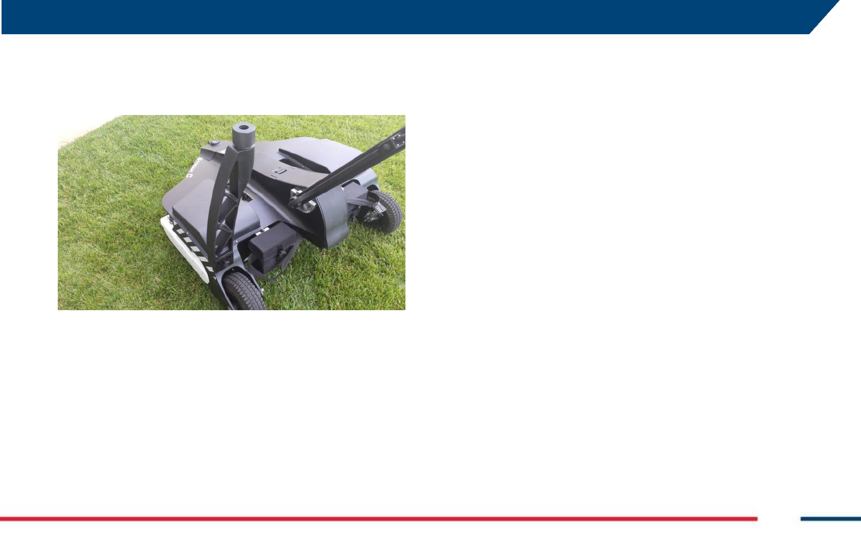
Mounting the hauling kit (optional) 4.6
An optional hauling system is also available with Stream-C. The system is
operated by hooking one end of the hauling system (part “A” of Fig. 4.15)
to the vehicle, and joining the opposite end to the frame of the pivoting
wheel of the frame (“B” in Fig. 4.15). In this case, the handle must be in
folded position, as shown in Fig. 4.15, and the height of the system is
adjusted through a remote control connected to the end side on the handle
(the same connector used for operating the electric engine) (“C” in Fig.
4.15).
Fig. 4.15 – mounting the hauling system
A
B
C
APPENDIX A. Disclaimer
IDS GeoRadar s.r.l. MN/2016/011 Rev 1.0 Draft 23/ 36
Mounting the GPS pole support (optional) 4.7
An optional GPS pole support can easily be mounted at the left rear side of
the main frame (Fig. 4.16). To do this, just slide the metal part of the
support from left to right of the frame.
Fig. 4.16 –Mounting the GPS pole support
GPS requirements 5
As the Stream-C system can be operated with a GNSS to position the scans
in real time without the need of creating a grid, the operator should
consider the following requirements relating to the positioning device:
1. Dual frequency (L1+L2);
2. Positioning update greater than 5 Hz;
3. RTK: connection to a base station via radio link (UHF or
GSM) or connection to a Continuously Operating Reference
Station (CORS) via internet;
4. NMEA output;
5. Serial cable (RS232) is required, alternatively the GPS can
be connected to the laptop via Bluetooth.
Maintenance plan 6
Cleaning Information 6.1
Before cleaning any external parts of the apparatus, make sure that all
cables have been disconnected, including the power supply cable. If a damp
cloth is used, make sure it is not too wet, to avoid any damage to the
electrical components of the equipment. Wait until the equipment is totally
dry before reconnecting the cables.
The Stream-C should be cleaned periodically using a damp cloth.
Do not use solvents or abrasive detergents.
Do not apply liquid directly to the electrical contacts of the various
connectors. If a specific spray is used to clean the PC TFT monitor, make
sure it is not flammable; in any case, do not spray it directly on the screen,
instead, spray it onto the cleaning cloth.

APPENDIX A. Disclaimer
IDS GeoRadar s.r.l. MN/2016/011 Rev 1.0 Draft 24/ 36
Battery Removal Information 6.2
Laptop Batteries:
For the battery removal instruction, please do refer to the PC user’ manual.
Radar batteries:
Manufacturer: FIAMM FG21202 / SAFT MP176065
Type: Rechargeable lead acid / rechargeable lithium-ion
Characteristics: 12V & 12Ah / 15V & 6.8Ah
Removal instructions:
Disconnect the battery from the instrument:
pull the connector wings; .1
separate the connectors; .2
Remove the battery from the cover (optional) opening the strap.
Periodical Check 6.3
The Operator should periodically check the status of the antenna wearing
sledge, the LAN cable, and the tires.
The Sledge should be periodically checked out to verify when it
needs to be removed and replaced.
The LAN cable should be verified at each use of the system, in order
to check out whether connection to the PC and to the Georadar,
are integer and no damages occurred. In case of any damage,
remove and replace it.
The tires, should be verified at each use of the system in order to
check out whether their internal pressure and the consumption,
are compatible with a safe use of the system. In case of any
deviation from the above either, inflate the tires and/or replace it,
as deemed.
IDS On-line assistance 7
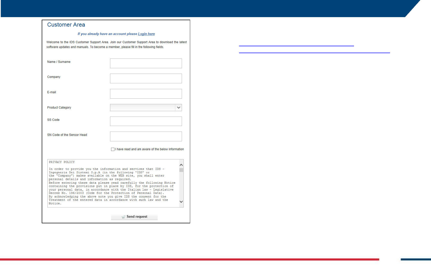
Download area 7.1
The Georadar section of the IDS website has a download area
accessible from the customer to get the latest update of software,
manuals, guides and other useful tools.
To do this the first step is to fill the registration form, accessible
from https://www.idscorporation.com/georadar/more-
information/georadar-customer-area-logged/request-an-account
(Fig. 7.1).
APPENDIX A. Disclaimer
IDS GeoRadar s.r.l. MN/2016/011 Rev 1.0 Draft 25/ 36
Fig. 7.1 – Registration form
The request will be handled by the Customer Care of IDS, then the
user will receive an email with its credentials to access the
download area, that he has to enter in
https://www.idscorporation.com/georadar/more-
information/georadar-customer-area-logged/customer-area-login.
Remote assistance using Webex Support Center 7.2
The Webex Support Center is a service that allows the activation of
a two host session, making an application or the desktop available
to the other user or letting the user capture another remote
desktop.
It can be used to perform web conferences and presentations.
It is easy to use thanks to a simple and intuitive interface.
Since there are no firewalls or other types of network
configurations, it is a fast and secure means of reaching any client
host in any part of the world. In fact, the client only has to accept to
download a small plug used to permit the service authentication
and function.
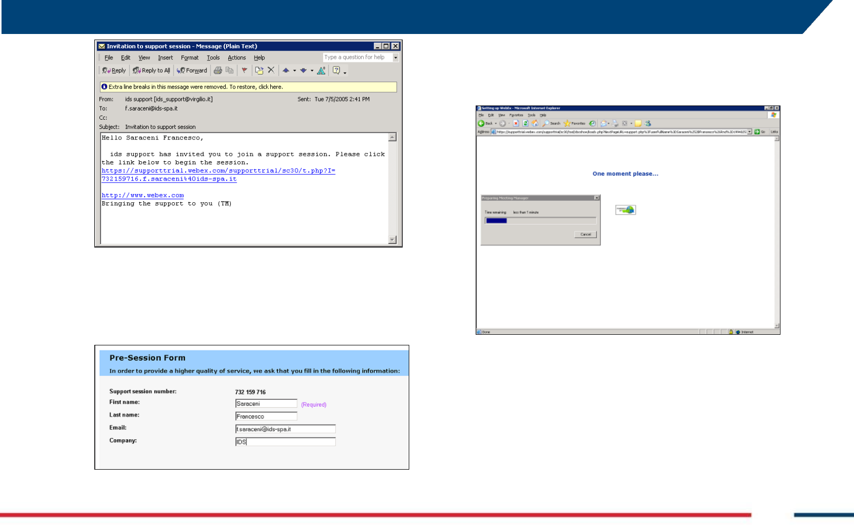
How to use the Webex service 7.2.1
The user will receive an email from IDS Customer Care containing a
link to the support session (see Fig. 7.2).
APPENDIX A. Disclaimer
IDS GeoRadar s.r.l. MN/2016/011 Rev 1.0 Draft 26/ 36
Fig. 7.2 – IDS e-mail sent to the client
Clicking on the link in the email, the following window appears.
Insert the user data into the form (see Fig. 7.3).
Fig. 7.3 – Client data insertion form
Clicking Submit, the following page appears showing a downloading
bar. The session starts as soon as the download is complete. (see
Fig. 7.4).
Fig. 7.4 – Webex Set up window
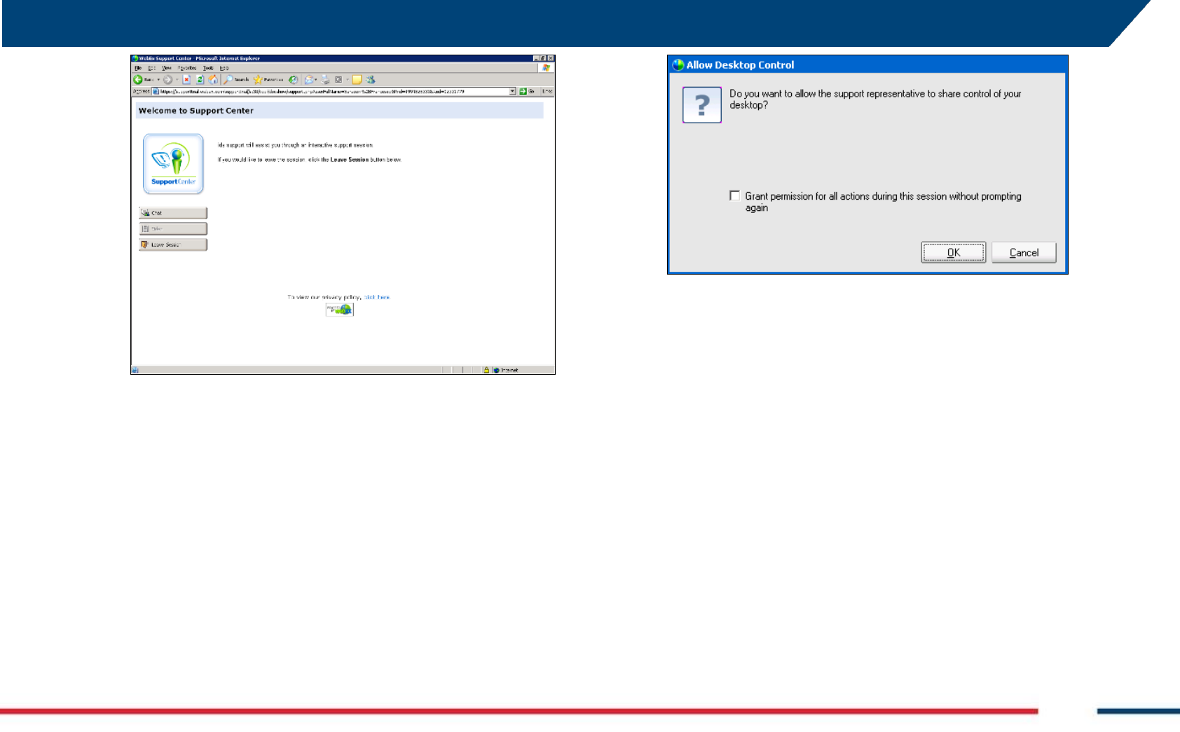
As shown in the following screen (see Fig. 7.5) the user is given a
console, containing the Chat, Video and Leave Session commands.
APPENDIX A. Disclaimer
IDS GeoRadar s.r.l. MN/2016/011 Rev 1.0 Draft 27/ 36
Fig. 7.5 - Welcome to Webex Support Center window
At this point, IDS Customer Care can perform a range of operations
on the user desktop:
Request control of the desktop using the Request Control
command;
Give the user control of the IDS desktop using the Share
Control command;
Request to display the remote desktop using Request View;
Share the visualization of the IDS desktop using Share View.
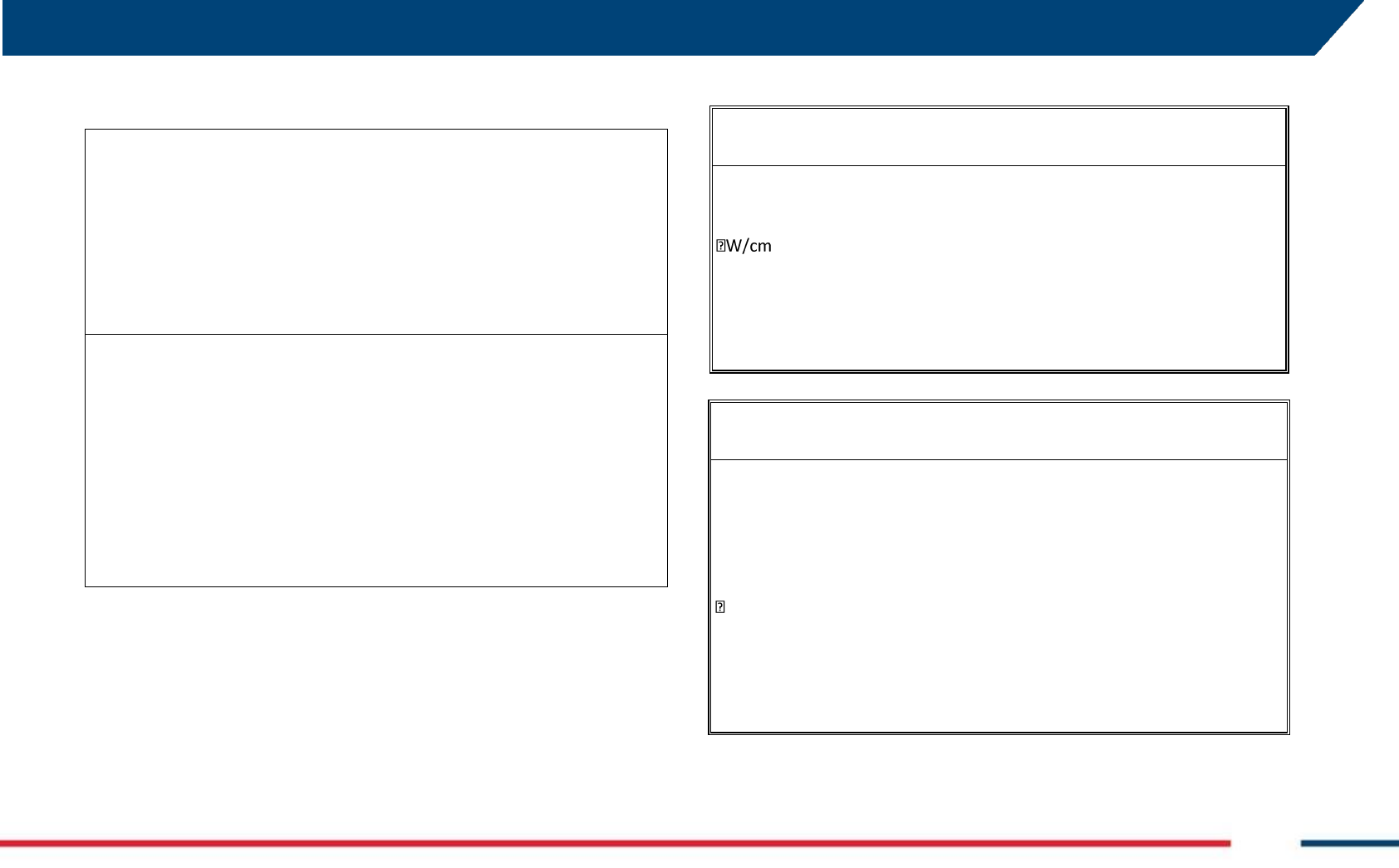
Before each command is activated, the user is asked for
confirmation through the window shown in Fig. 7.6.
Fig. 7.6 – Command acceptance window

APPENDIX A. Disclaimer
IDS GeoRadar s.r.l. MN/2016/011 Rev 1.0 Draft 28/ 36
APPENDIX A DISCLAIMER
1. Generals.
i. The present Disclaimer applies to all products (the “Products”)
designed, produced and distributed by Ingegneria Dei Sistemi SpA
- Georadar Division (“IDS”), its Subsidiaries, Affiliated and
authorized Distributors. IDS reserves full ownership and intellectual
property rights of any “Information” contained in this Disclaimer
including Trade Marks and Graphics. No part of this Disclaimer
may be used or reproduced in any forms without the prior written
agreement of IDS.
ii. In the event that any provision of this Disclaimer may be invalid,
unlawful or incapable of being enforced by a rule of law, all other
provisions shall, nonetheless, remain in full force and effect.
Failure to either enforce or exercise any right, privilege, or legal
remedy at any time, any provision contained in this Disclaimer,
shall not be deemed a waiver of such provisions or right, remedy,
or privilege.
iii. This Disclaimer shall be interpreted, governed, construed and
enforced in accordance with the laws of Italy. Buyer hereby
consents to the exclusive jurisdiction of Pisa
1. Initial Precautions for Setting-up and Use of the Products.
i. The Buyer, for setting-up and using the purchased Products, shall
consult the official documentation provided by IDS for the Products
(“Reference Documentation”) and carefully ascertain the
compliance with national laws and requirements, which may limit or
even forbid their use.
ii. For Products which shall operate by circulation in Public
Areas/Roads, with or without moving traffic, Buyer/User shall verify
the approval of local authority and/or site’s owner according to their
specific procedures. IDS shall not be liable for any direct, indirect,
special, incidental or consequential damages or injuries, including
without limitation, lost revenues or lost profits, resulting by un-
authorized use of the Products in Public Areas/Roads.
iii. For IBIS Products Family, Buyer/User warrants:
that these Products are not being used, in the design,
development, production or use of chemical, biological,
nuclear ballistic weapons. Buyer/ User will defend,
indemnify and hold IDS harmless against any liability
(including attorney’s fees) for non-compliance with the
terms of this article.
that no operation or use of the IBIS products shall be
started before its designated Operator/s has got the IBIS
User Certificate, as defined by IDS specific procedure
which the Buyer confirms to know and accept.
iv. For Products which include specific “Operational” software with
automatic data processing and analysis “Tools”, i.e. the IBIS
Products, User shall be aware that the results provided by these
“Tools” may be not error free. User that completely relies on the
outcomes provided by these Tools only, does it at his own risk.
v. In no event IDS shall be liable for special, direct, indirect, incidental,
exemplary, punitive or consequential damages including, but not
limited to, loss of profits or revenue, caused by the use of the
Products, either separately or in combination with other products or
relied upon the results provided by the above “Tools”.
2. Disclaimer for the “Use” of the Products.
i. The User shall follow the instructions provided by IDS in its official
“Reference Documentation” for the Product, in particular the User’s
Technical Manual which contains all the specific steps and
recommendations for a correct setting-up and use of the Product.
ii. In no event IDS shall be liable for special, direct, indirect, incidental,
exemplary, punitive or consequential damages including, but not
limited to, loss of profits or revenue, caused by the missed or
incomplete observance of the instructions and prescriptions for the
use of the Products, either separately or in combination with other
products, in particular for the following main aspects:
a. Use of IDS Products outside its limitation of use, without
proper and adequate scientific/technical knowledge or
without specific training.
b. Use of results/outcomes of the measurements performed
by the Product aimed to safety aspects without using
adequate control procedures and assessment by skilled
personnel.
c. Opening of the Equipment (for HW Products) without
express written authorization of IDS.
d. Unauthorized changes and additions to the Products.
e. Use of the Products connected to suspected non-working
equipment or with equipment (mainly PC) having

APPENDIX A. Disclaimer
IDS GeoRadar s.r.l. MN/2016/011 Rev 1.0 Draft 29/ 36
characteristics non in compliance with the required
specifications of IDS on not expressly authorized by IDS.
f. Poor or faulty operation of the electrical and
telecommunication networks not directly managed by IDS
or its delegates.
g. Poor or faulty operation Software/Hardware of the third
parties connected with IDS Equipment.
h. Poor or faulty operation of the Products due to Software
Virus which infected the Products after their delivery.
i. Use of the Products which have encountered suspected
manumissions, accidents, electrostatic shocks, flashes, fire,
earthquake, flooding or other natural disasters or
unexpected events.
j. Use or storage of the Products outside the limits of the
“Operational Temperature Range” specified by IDS.

APPENDIX B. Warranty
IDS GeoRadar s.r.l. MN/2016/011 Rev 1.0 Draft 30/ 36
APPENDIX B WARRANTY
A. h Standard Warranty Conditions
1. IDS Ingegneria dei Sistemi S.p.A, (hereinafter referred to as IDS or Seller),
warrants that its products shall be free from defects in material and
workmanship, for a period of 12 months from the delivery date duly registered
and certified (“Effective Date”) in the “Warranty Registration Form” enclosed
hereto. IDS shall repair or replace Products or parts thereof found faulty (the
“Faulty Parts”) which are returned to IDS, and which, at IDS’s judgment, were
defective or became defective during its normal use. Seller’s obligations shall
not apply to Faulty Parts that:
(a) Buyer do not properly store, install, use, or maintain;
(b) Buyer modify, or perform tests which are not approved in writing by
the Seller;
(c) Buyer have subjected to any kind of misuse, detrimental exposure
beyond its intended purpose or damaged in an accident or by natural
disaster or calamities.
(d) Are repaired by other than IDS personnel; in which have been installed
HW/SW accessories not supplied by IDS; are integrated or connected
to equipment different from the ones supplied by IDS (except the PC
data Logger conform to IDS specifications);
(e) Whose operational software was not installed as per IDS instruction
(see IDS User’s Guide for the Data Acquisition Software);
2. Seller’s Products may include specific “Operational” software with automatic
data processing and analysis tools (SW) supplied under a License agreement
(EULA). While every effort is made to ensure the accuracy of the
information/results provided by these tools, they must not be intended as a
substitute for people analysis; rather, they have to be intended as an advisor
and the user must not completely rely on the results provided by them. Under
no circumstances does IDS warrant that the SW will operate uninterrupted or
error free The SW is provided “as is” without warranty of any kind. IDS
warrants for a period of sixty (60) days from the Effective date that, under
normal use, the SW support media will be free of defects in material and
workmanship; in such case the provisions of above point a) apply
3. Any different warranty, granted by the Buyer to its retailers and clients, even
as final consumers, pursuant to the European Union law in force regarding the
rights of the consumers, does not engage IDS in anyway.
4. The above mentioned warranty excludes any other remedies and it has to be
considered the only and exclusive remedy foreseen for the Buyer and its
retailers and clients, with reference to IDS Products purchase, being,
expressively understood that any kind of limitation and/or discharge of
responsibility provided by the present warranty is referred to both (I) the
responsibility as against any third parties, pursuant to the legislation regarding
the producer responsibility and (II) the warranty provided by the law in force.
B. Warranty Procedure
1. To proceed in the application of warranty terms, Buyer shall have to contact
IDS Customer Care Office to get the clearance to return the Faulty Parts.
2. The Faulty Parts once received by IDS will be inspected to verify they are
eligible for repair or replacement..
3. Buyer is responsible for ensuring that the Faulty Parts be returned to IDS with
a suitable packing (it is recommended that the original packing be saved for a
better understand of the failure cause); IDS will not be obliged to repair or
replace Faulty Parts damaged from abuse, misuse, negligence, accident loss or
damage in transit.
4. The Shipping costs for Products returned during the warranty period, are as
follows:
(f) From Buyer Site to Seller site shipping costs, as per Incoterms CIP,
are borne by Buyer
(g) From Seller Site to Buyer site shipping cost, as per Incoterms CIP,
are borne by Seller
5. The warranty period on the repaired or replaced Faulty Parts is 6 (six) months
or the unexpired portion of warranty on such Faulty Parts whichever date
comes later.
C. Special Warranty Conditions for IBIS Products
Without prejudice to the Warranty terms defined in the above Clauses A and
B, the following special conditions apply to the IBIS products.
1. IDS offers to the Buyer, optionally, special Support and Maintenance Plans to
be performed along the life of the equipment. These plans set forth special
Warranty conditions which are detailed in the relevant options purchased.

APPENDIX B. Warranty
IDS GeoRadar s.r.l. MN/2016/011 Rev 1.0 Draft 31/ 36
2. IBIS Product Family is subject to export/import regulations as per EU export
control regime Council Regulation (EC) No. 428/2009 and successive
amendments. The category of exportation for IBIS F product family is 6A008.d.
Buyer warrants that the IBIS Products to be purchased: a) shall not be re-
exported, directly or indirectly, outside Buyer’s country in violation of any law
or regulation or to embargoed or otherwise restricted countries, b) shall not
be used, in the design, development, production or use of chemical, biological,
nuclear ballistic weapons. It is Buyer’s responsibility to know the law
pertaining to export/import procedures in the country of destination of the
Products. Buyer will defend, indemnify and hold Seller harmless against any
liability (including attorney’s fees) arising out of Buyer’s failure to comply with
the terms of this article. Should the Authorities issue an export restriction
which leads to the cancellation of a purchase order already accepted by IDS,
IDS only liability shall be to return to Buyer any account paid without interests.
Buyer shall comply with the laws and procedures in force in the country of
destination of the Products.
3. IBIS can be used in Critical Monitoring for safety purposes applications, like
real time monitoring of unstable slopes including Opencast Mining. Buyer shall
be aware and agree that the assessment of the stability conditions of the
observed target must be tasked to skilled and certified operator/s able to
understand data supplied by either IBIS or others. The performance of IBIS can
be, in fact, influenced either by the parameters introduced by the operator/s
or by particular environmental conditions which may distort its outcomes, thus
giving rise to false or missing alarms.
4. IDS assumes no liability for any direct, indirect special, incidental or
consequential damages or injuries caused by such reliance or for the use of
IBIS Products by operator who have not achieved a training course certified by
IDS. Any person or entity that completely relies on information obtained from
the automated data processing/analysis tools only or by operators who have
not achieved a training course certified by IDS, does so at his own risk
D. Limited Liability
Without prejudice to the exclusion of liability stated at the above Clause C.
1. Seller’s sole obligation and liability under this Agreement shall be limited to
the repair or replacement of the Product, or the refund of the purchase price
at the Seller’s sole option. This Article sets forth the sole and exclusive
remedies for claims based upon defects or nonconformity of the Products,
whether the claim is on contract, warranty, tort (including negligence), strict
liability, or otherwise.
The cumulative liability of Seller, including its subcontractors or suppliers, for any
and all claims, including but not limited to claims based on Seller’s negligence of
any degree, strict liability, breach of contract, warranty, reliance on the accuracy,
reliability, or timeliness of the information provided by the SW, patents or
otherwise, shall not exceed the sums cashed by IDS for the purchased Products,
which give rise to the claim, and any such liability shall terminate upon the
expiration of the warranty period.

APPENDIX C. Technical Specification
IDS GeoRadar s.r.l. MN/2016/011 Rev 1.0 Draft 32/ 36
APPENDIX C TECHNICAL SPECIFICATION
AR600V24H10 antenna
SPECS
Lenght
1200 mm
Width
570 mm
Height
200 mm
Weight
20 kg
Enclosure Class
IP 65
Temperature Range
-10 °C ÷ + 40 °C
Input voltage range
100 ÷ 240 V AC
Power Consumption
60 W
External Fuse
20 A ATO
LAN
RJ 45 10 ÷ 100 Mbit

INDEX
IDS GeoRadar s.r.l. MN/2016/011 Rev 1.0 Draft 33/36
APPENDIX D RECYCLING
RECYCLING
The crossed out wheeled bin symbol shown on the equipment indicates
that the product must be recycled separately from other waste at the end
of its useful life.
Separate waste disposal of this product at the end of its useful life will be
organised and managed by IDS. When you decide to dispose of the
equipment, contact IDS and follow the system that IDS has set up to permit
the separate collection of the apparatus at its life end.
Adequate separate collection for its subsequent recycling, treatment and
environmental friendly disposal contribute towards avoiding any
unnecessary effects on the environment and to health and favour the reuse
or recycling of the materials that make up the equipment. Unauthorised
disposal of this product as unsorted waste by its possessor will lead to an
administrative penalty foreseen by national regulations.
APPENDIX E CONFORMITY TO EUROPEAN REGULATION
CONFORMITY TO EUROPEAN REGULATIONS
The equipment conforms to the following requirements set by EC
regulations, including subsequent modifications, and to the legislation set
by the member states that implement these regulations:
1999/05/EEC Radio Directive
Warning: this equipment is destined for use in industrial environments
(Class A apparatus). In residential, commercial and light industry
environments, this apparatus may generate radio interference: in this case,
the user may be required to operate while taking appropriate
countermeasures.
The apparatus is sensitive to the presence of external electromagnetic
fields, which may reduce its performance.

APPENDIX D. IMPORTANT NOTICE FOR THE US CUSTOMER
IDS GeoRadar s.r.l. MN/2016/011 Rev 1.0 Draft 34/ 36
APPENDIX F IMPORTANT NOTICE FOR THE US CUSTOMER
FCC ID: UFW-AR600V24H10
This device complies with part 15 of the FCC Rules:
Operation is subject to the following conditions:
1. This device may not cause harmful interference, and
2. This device must accept any interference received, Including interference that
may cause undesired operation
Warning: Changes or modifications to this unit not expressly approved by the
party responsible for compliance could void the user’s authority to operate the
equipment.
Operation of this device is restricted to law enforcement, fire and rescue officials,
scientific research institutes, commercial mining companies, and construction
companies. Operation by any other party is a violation of 47 U.S.C. § 301 and could
subject the operator to serious legal penalties.
Coordination Requirements.
(a) UWB imaging systems require coordination through the FCC before the
equipment may be used. The operator shall comply with any constraints on
equipment usage resulting from this coordination.
(b) The users of UWB imaging devices shall supply detailed operational areas to the
FCC Office of Engineering and Technology who shall coordinate this information
with the Federal Government through the National Telecommunications and
Information Administration. The information provided by the UWB operator shall
include the name, address and other pertinent contact information of the user, the
desired geographical area of operation, and the FCC ID number and other
nomenclature of the UWB device. This material shall be submitted to the following
address:
Frequency Coordination Branch., OET
Federal Communications Commission
445 12th Street, SW
Washington, D.C. 20554
ATTN: UWB Coordination
(d) Users of authorized, coordinated UWB systems may transfer them to other
qualified users and to different locations upon coordination of change of
ownership or location to the FCC and coordination with existing authorized
operations.
(e) The NTIA/FCC coordination report shall include any needed constraints that
apply to day-to-day operations. Such constraints could specify prohibited areas of
operations or areas located near authorized radio stations for which additional
coordination is required before operation of the UWB equipment. If additional
local coordination is required, a local coordination contact will be provided.
(f) The coordination of routine UWB operations shall not take longer than 15
business days from the receipt of the coordination request by NTIA. Special
temporary operations may be handled with an expedited turn-around time when
circumstances warrant. The operation of UWB systems in emergency situations
involving the safety of life or property may occur without coordination provided a
notification procedure, similar to that contained in CFR47 Section 2.405(a)-(e), is
followed by the UWB equipment user.
Notice: Use of this device as a wall imaging system is prohibited by
FCC regulations.
APPENDIX D. IMPORTANT NOTE FOR CANADIAN CUSTOMERS
IDS GeoRadar s.r.l. MN/2016/011 Rev 1.0 Draft 35/ 36
APPENDIX G IMPORTANT NOTE FOR CANADIAN
CUSTOMERS
IMPORTANT NOTE FOR THE CANADIAN CUSTOMERS
IC Certification Number: 8991A – AR600V24H10
This device complies with the requirements of IC Standard RSS-220
This Ground Penetrating Radar Device shall be operated only when in contact with or
within 1 m of the ground.
This Ground Penetrating Radar Device shall be operated only by law enforcement
agencies, scientific research institutes, commercial mining companies, construction
companies, and emergency rescue or firefighting organizations.
NOTE IMPORTANTE POUR LES UTILISATEURS CANADIENS
Numéro de certification 8991A – AR600V24H10
Cet appareil est conforme aux exigences de la norme RSS IC-220
Cet équipement géoradar doit être utilisé que lorsqu’il est en contact ou à moins de 1
mètre du sol.
Cet équipement géoradar doit être utilisé que par des organismes d'application de la loi,
des instituts de recherche scientifique, des sociétés minières commerciales, des
entreprises de construction et de secours d'urgence ou les organisations de lutte contre
les incendies.
RADIO-FREQUENCY EXPOSURE COMPLIANCE
This product operated is usually operated at least 1 m from the operator.
Typical power density levels at a distance of 1 m or greater is below 1
2 (0.01 W/m2) which are far below the levels specified by the
current regulations.
Thus, this product pose no health and safety risk when operated in the
normal manner of intended use.
CONFORMITÉ D’EXPOSITION AUX FRÉQUENCES RADIO
Le produit doit être à au moins un mètre de l’utilisateur lorsqu’en
opération.
Le niveau de densité de puissance à une distance de 1 mètre et plus est de 1
W/cm2 (0.01 W/m2), ce qui est nettement inférieur aux niveaux spécifiés
par la réglementation en vigueur.
Ainsi, ce produit ne représente aucun risque pour la santé et la sécurité
lorsqu'il est exploité dans les conditions d'utilisation prescrites.

APPENDIX D. CONTACTS
IDS GeoRadar s.r.l. MN/2016/011 Rev 1.0 Draft 36/ 36
APPENDIX H CONTACTS
IDS GeoRadar s.r.l.
Via Enrica Calabresi, 24 – Loc. Montacchiello
56121 PISA - ITALY
Tel: +39.050.312411
Fax: +39.050.3124205
commercialoffice@idsgeoradar.com
Customer Care department:
customercare.gpr@idsgeoradar.com
Tel.: +39.050.3124356
Sales & Marketing department:
sales.gpr@idsgeoradar
Tel.: +39.050.3124352