IDS GeoRadar s r l HI-MOD Ground Penetrating Radar User Manual MN 2009 056 10 HW Himod france
IDS Ingegneria dei Sistemi SpA Ground Penetrating Radar MN 2009 056 10 HW Himod france
UserManual.wiki
>
IDS GeoRadar s r l
>
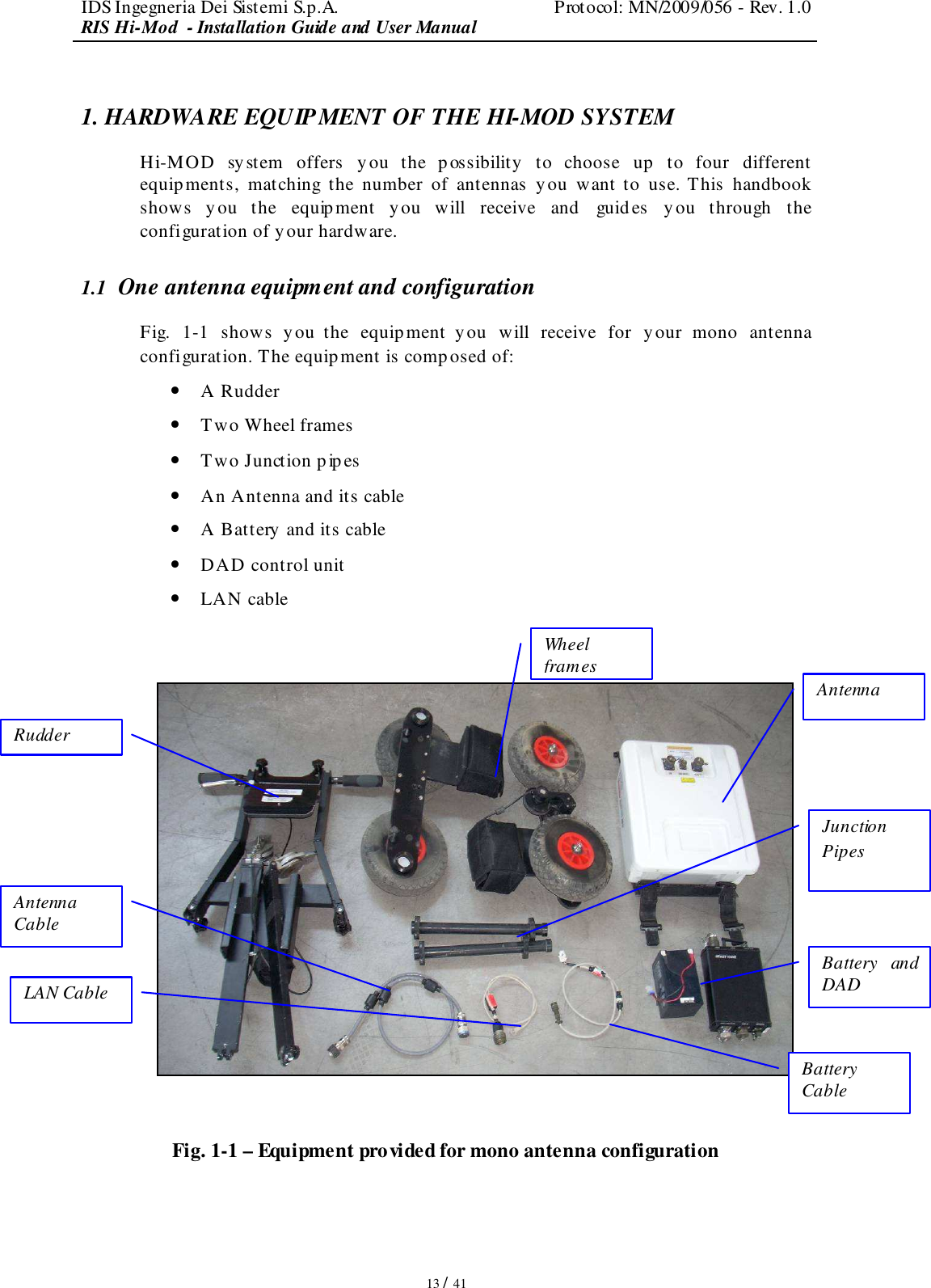
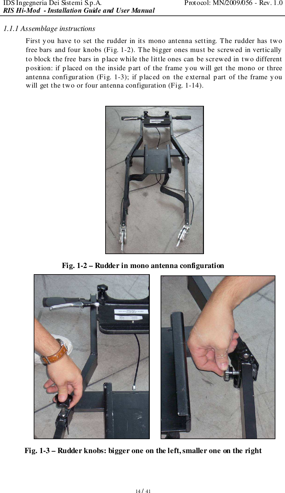
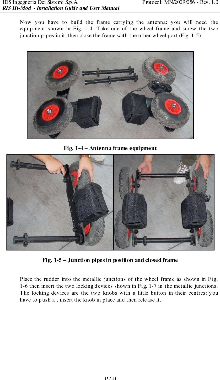
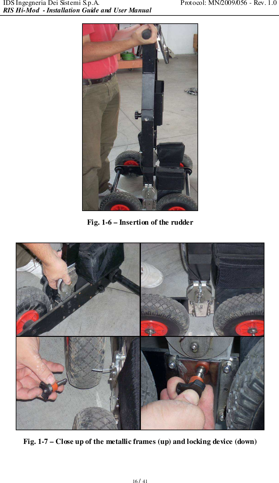
HI MOD User Manual
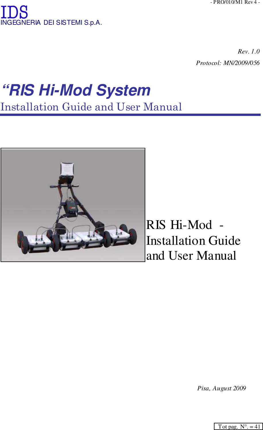
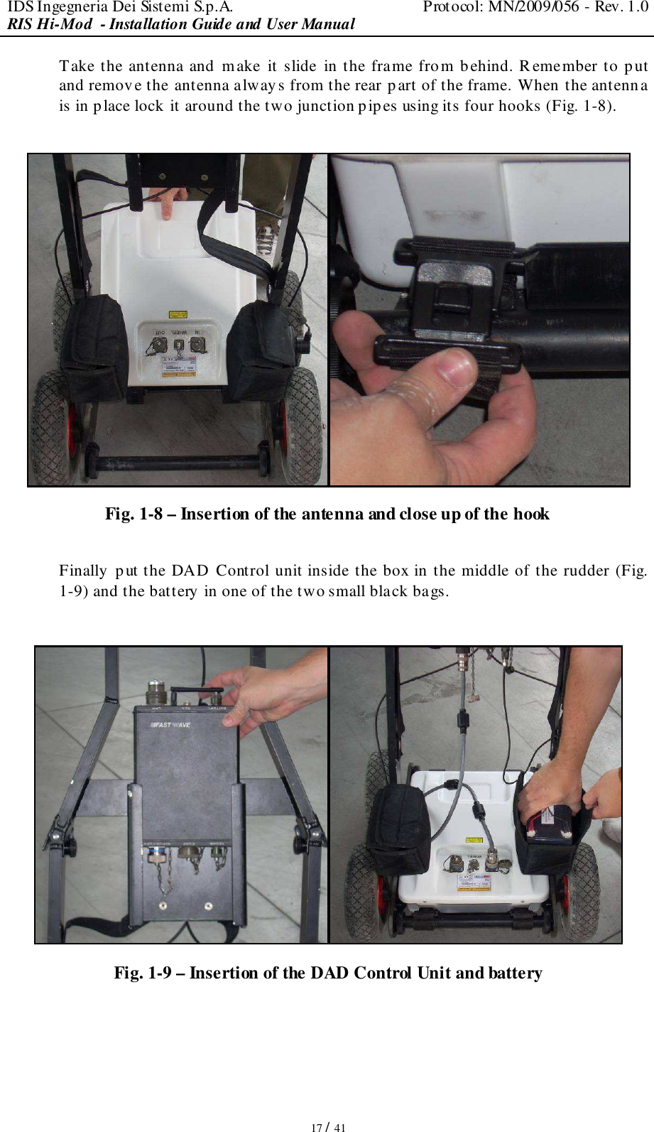
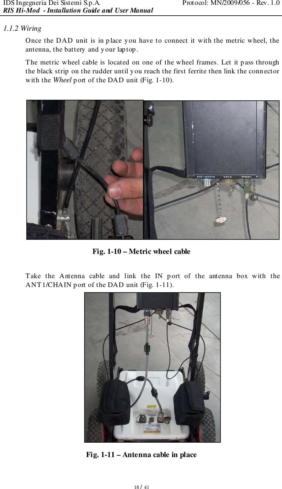
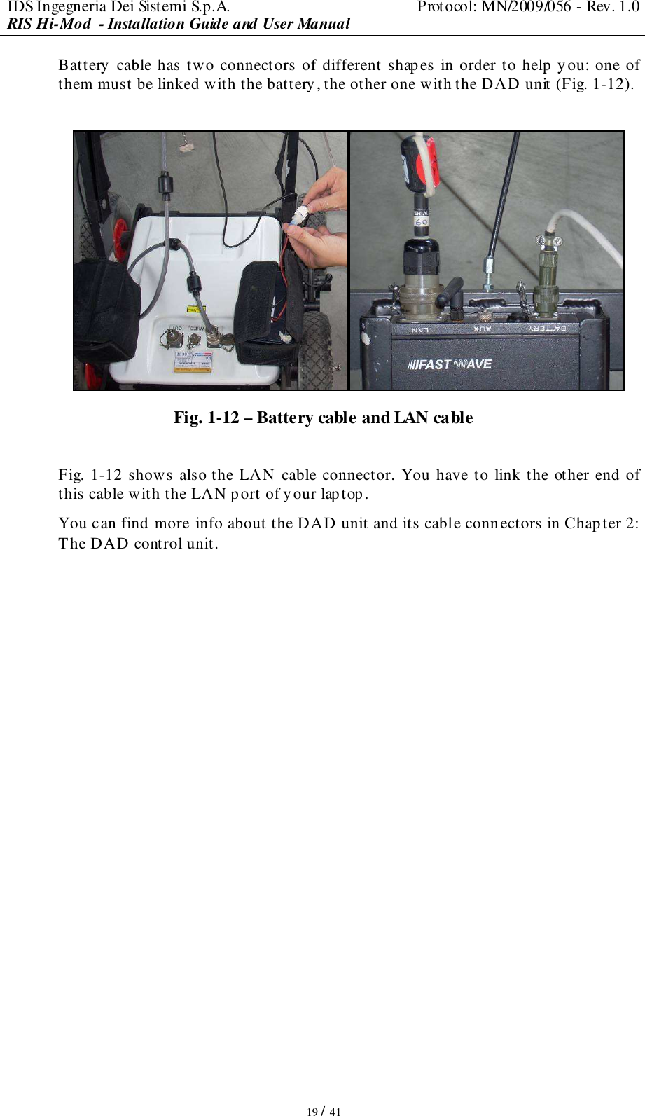
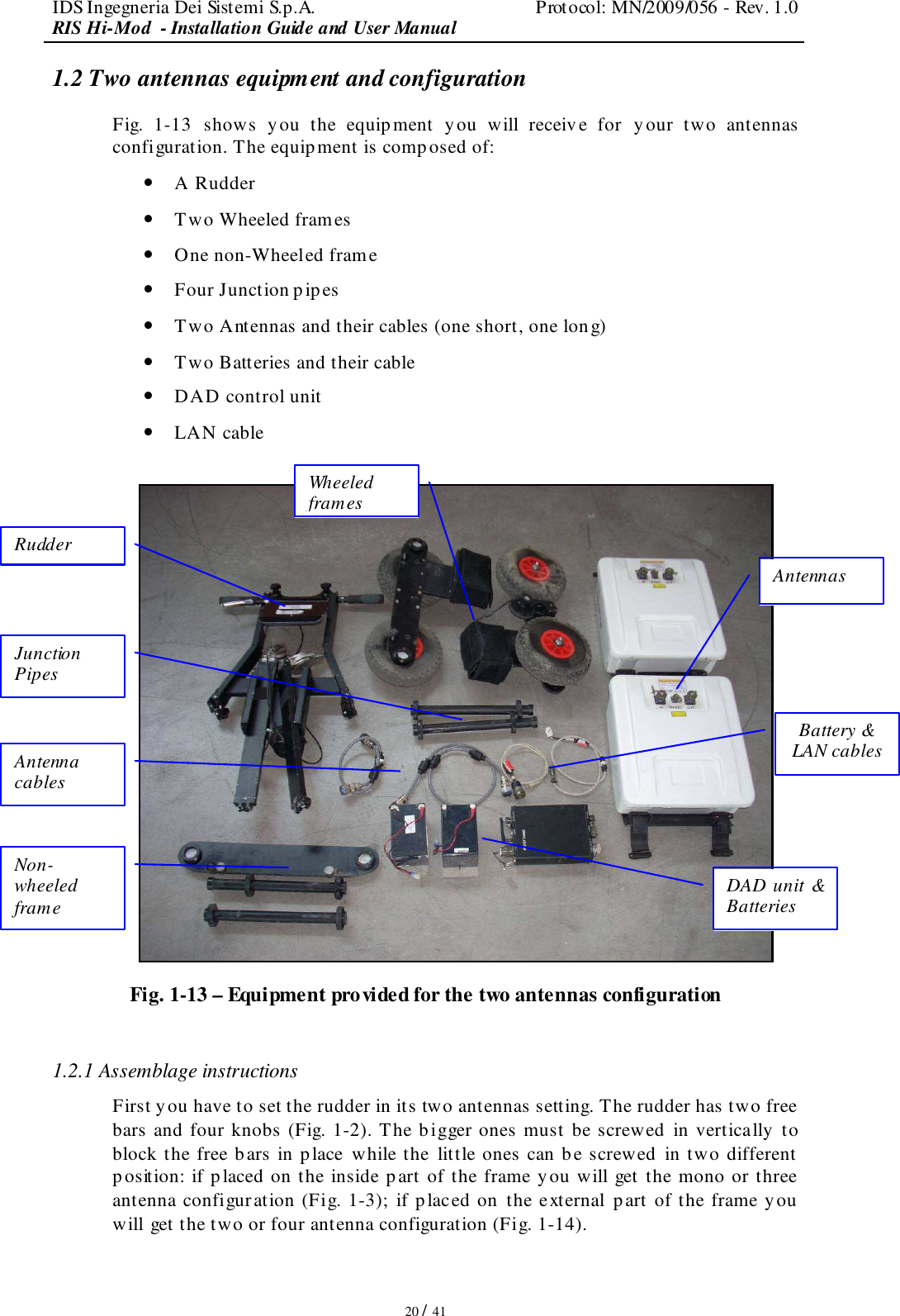
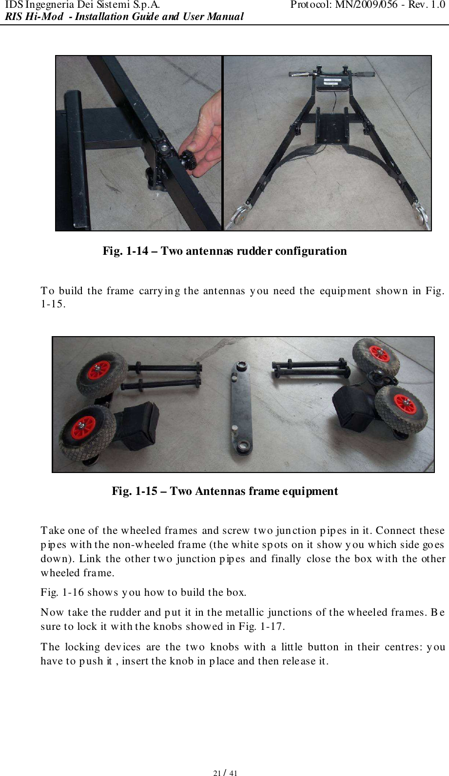
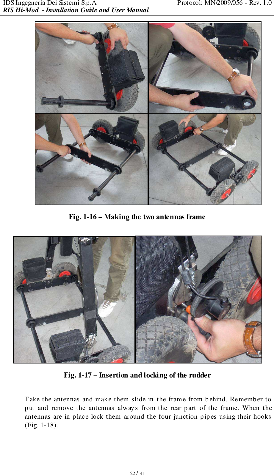
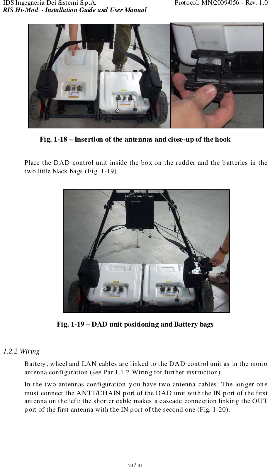
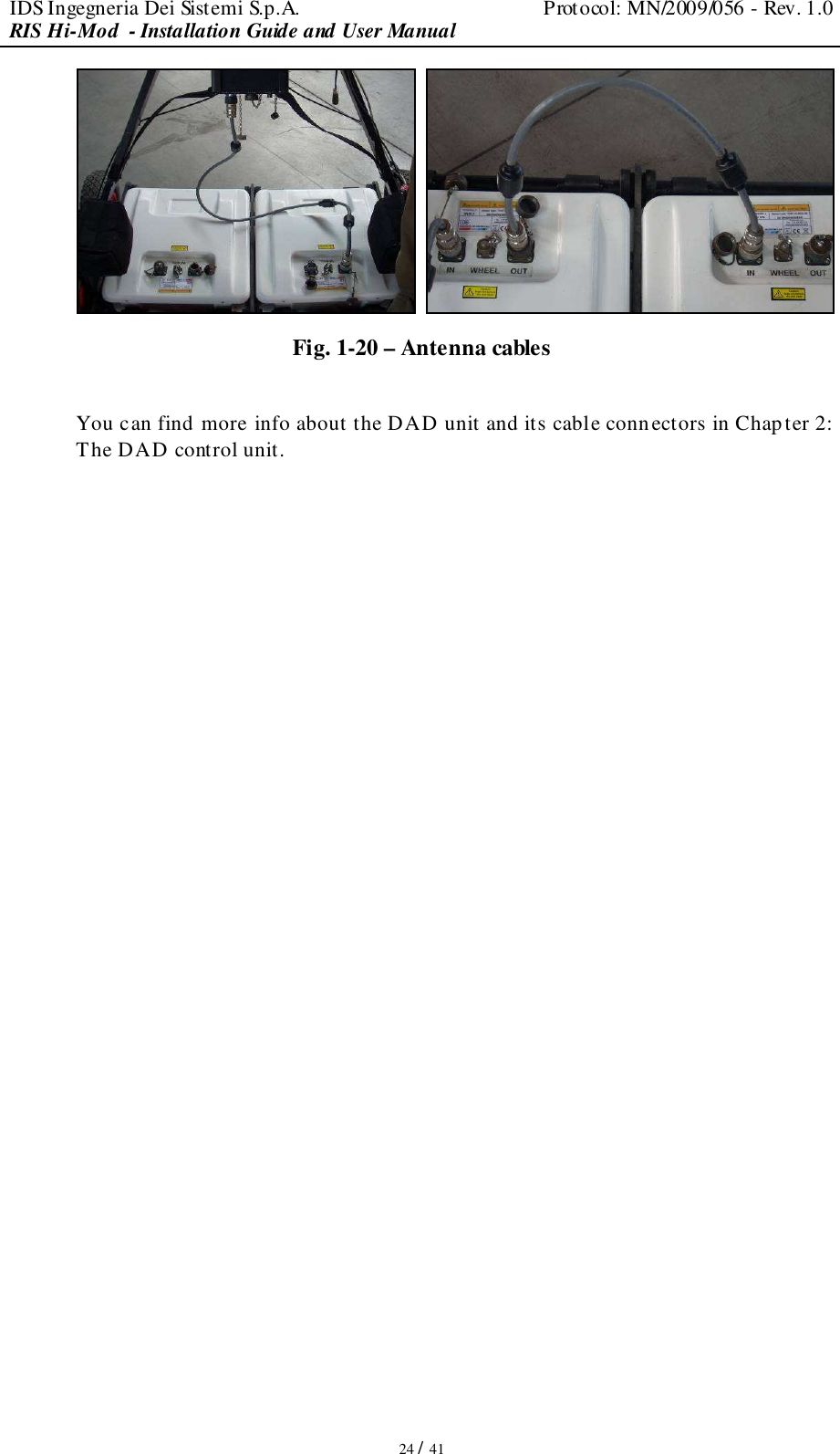
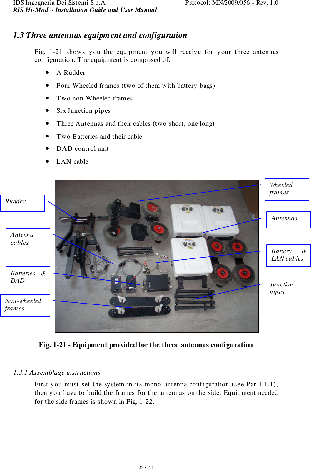
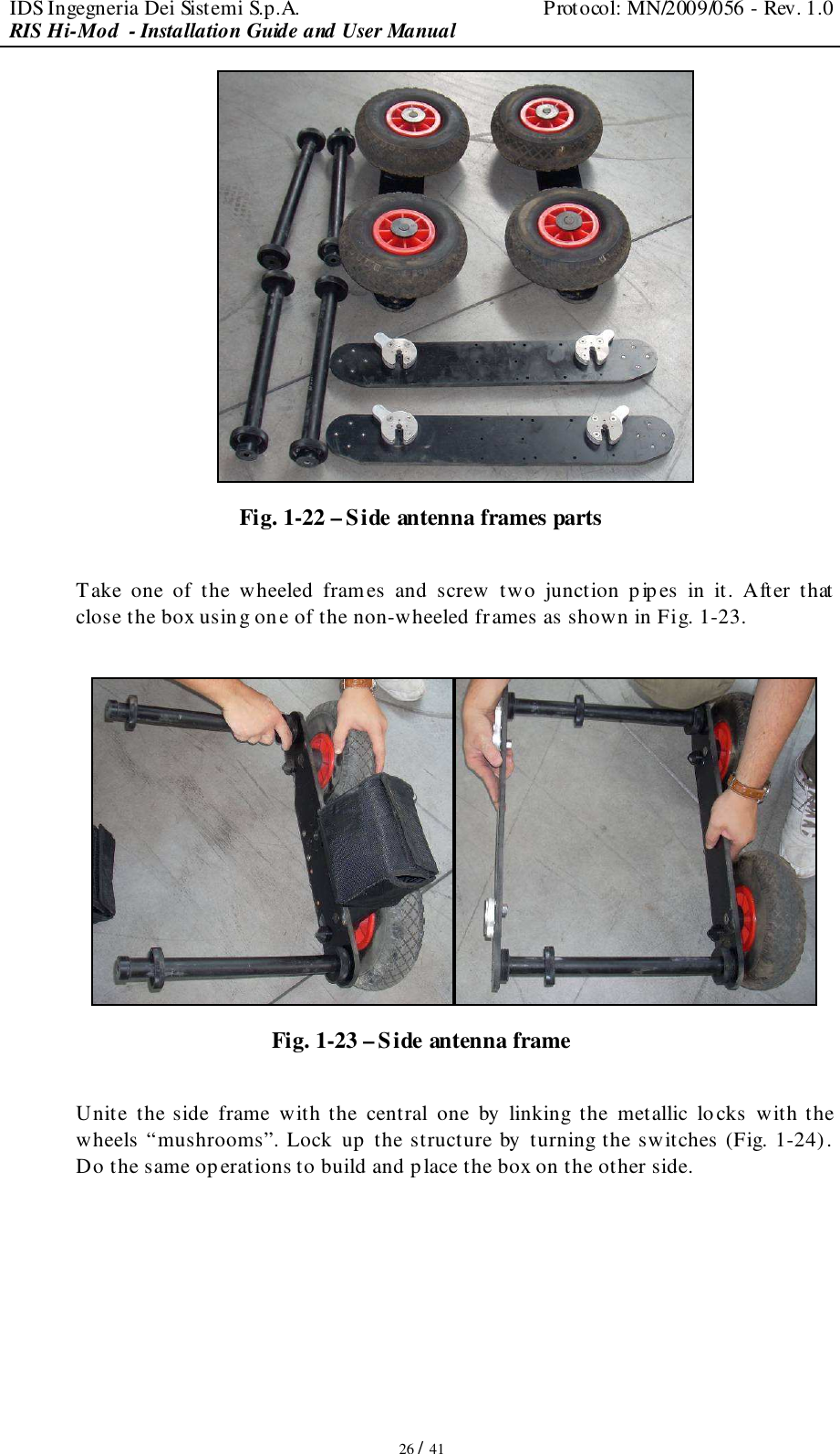
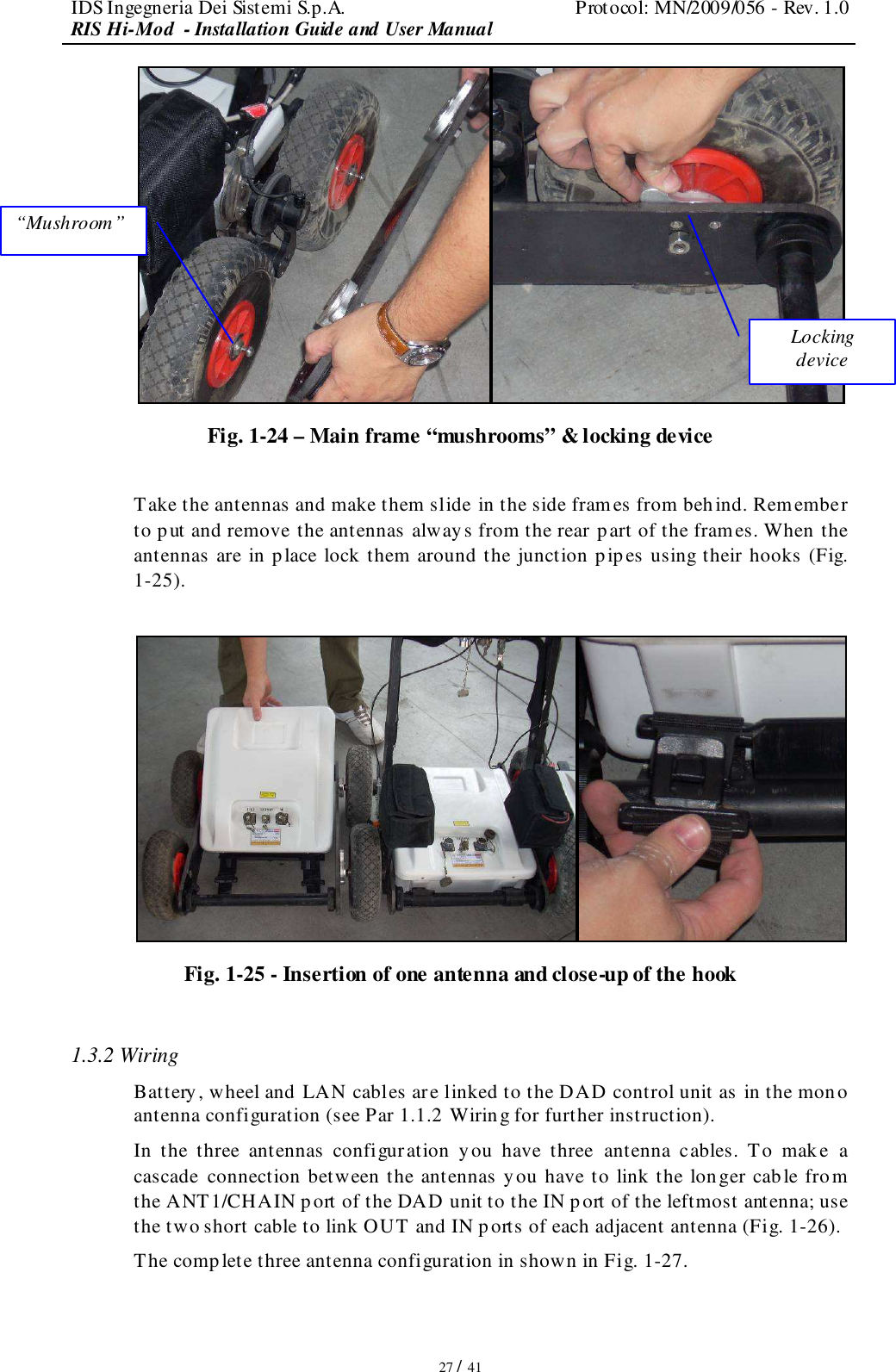
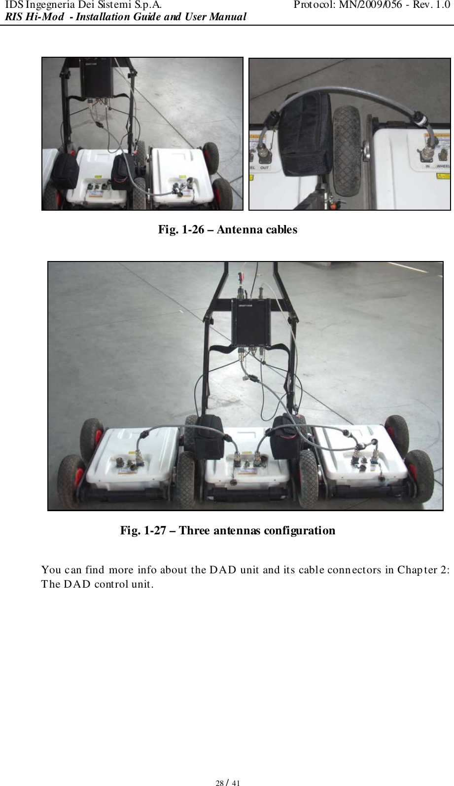
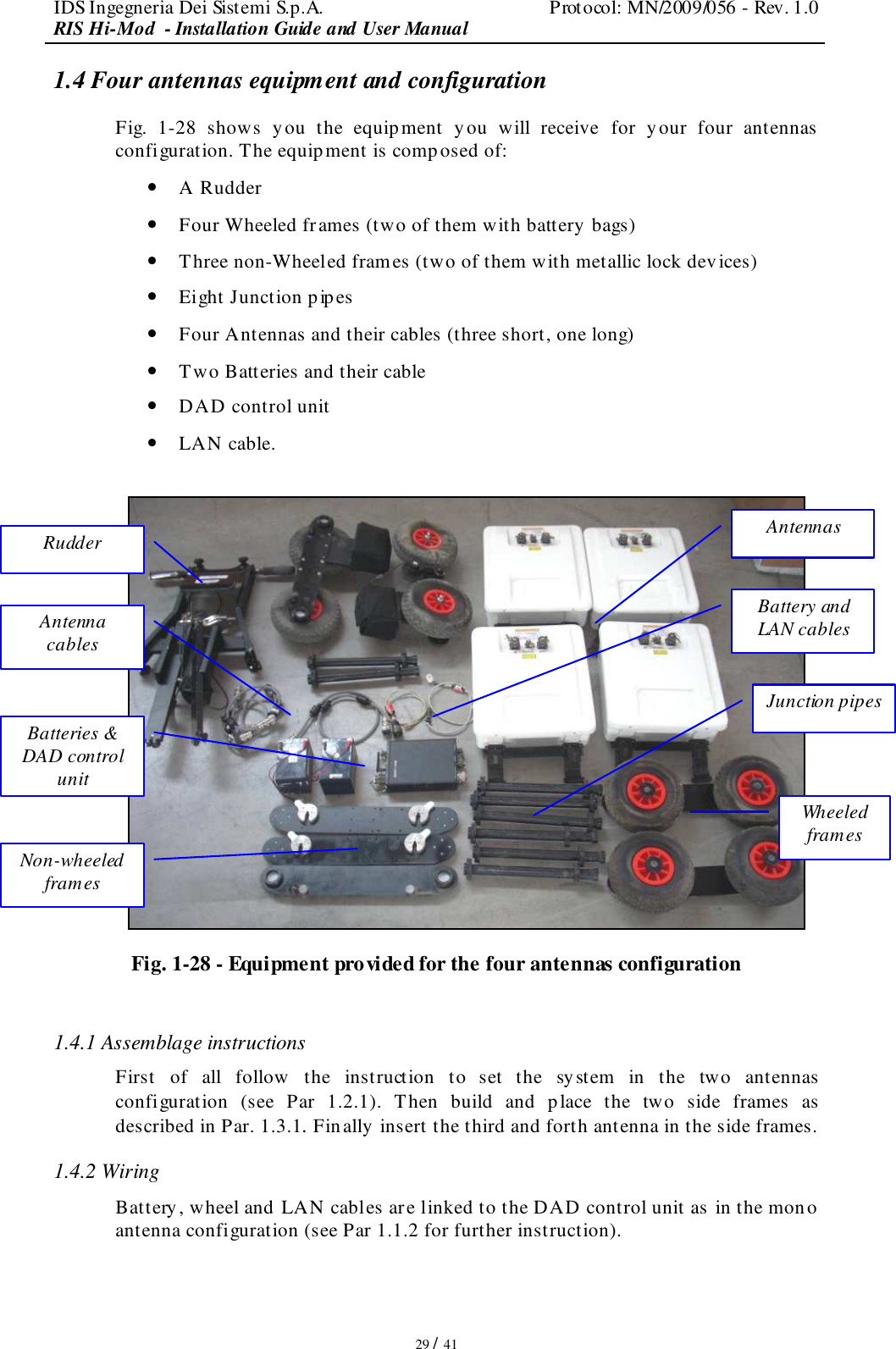
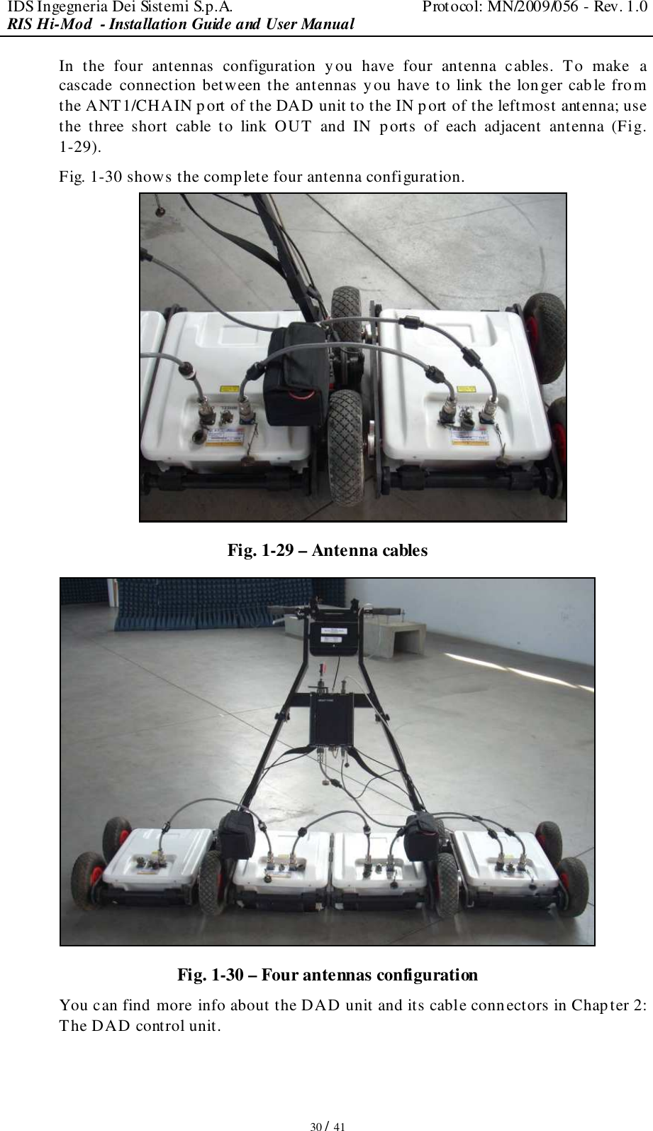
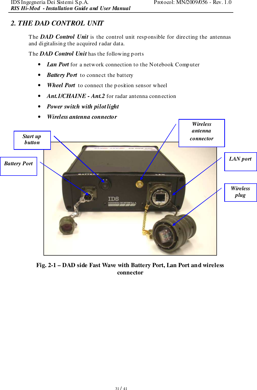
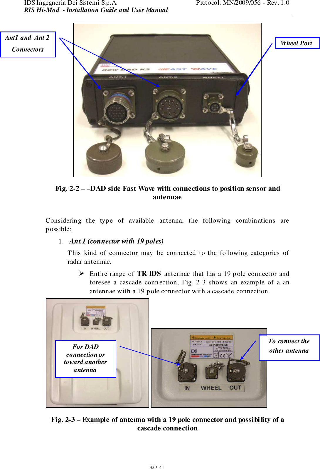
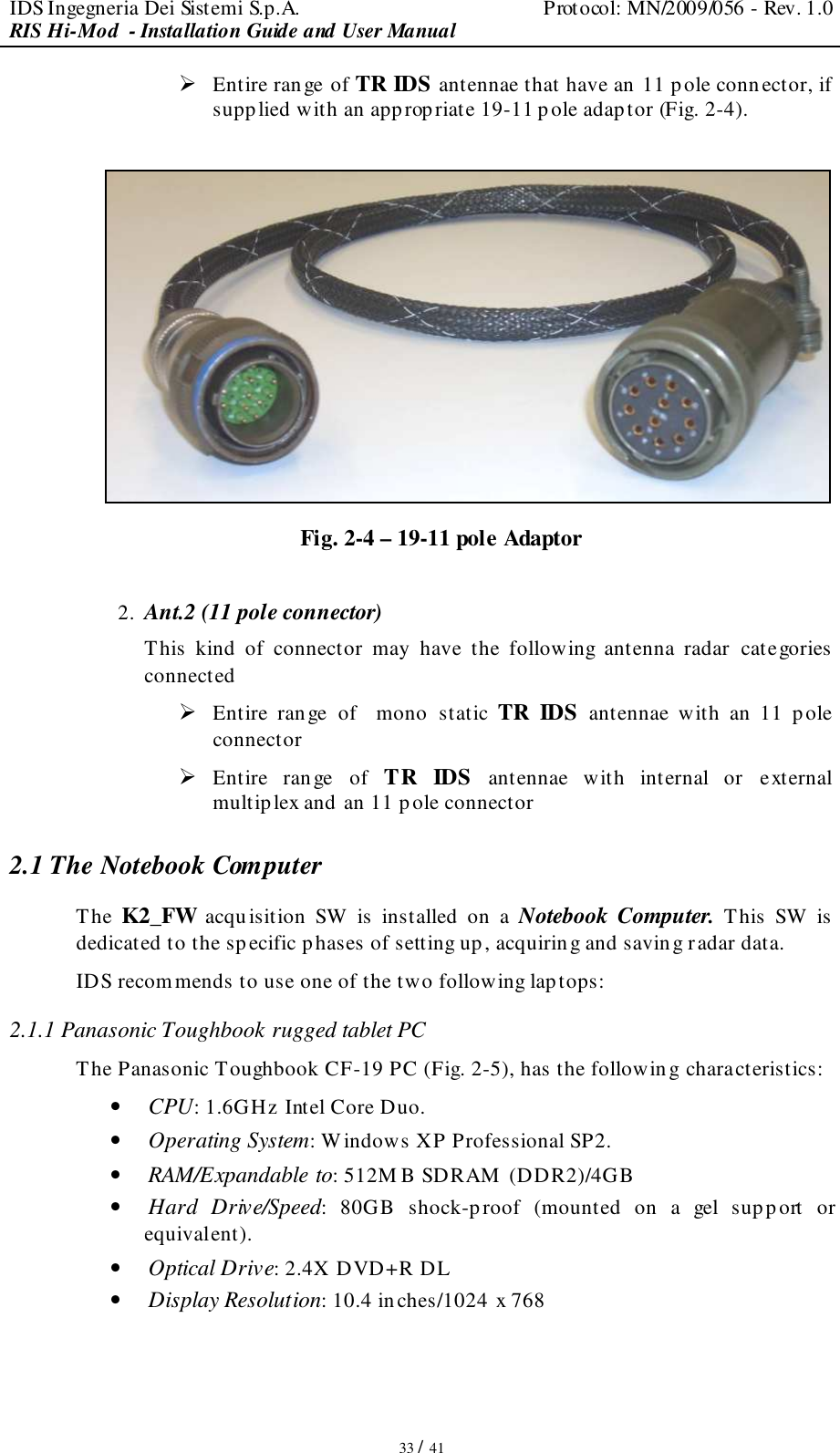
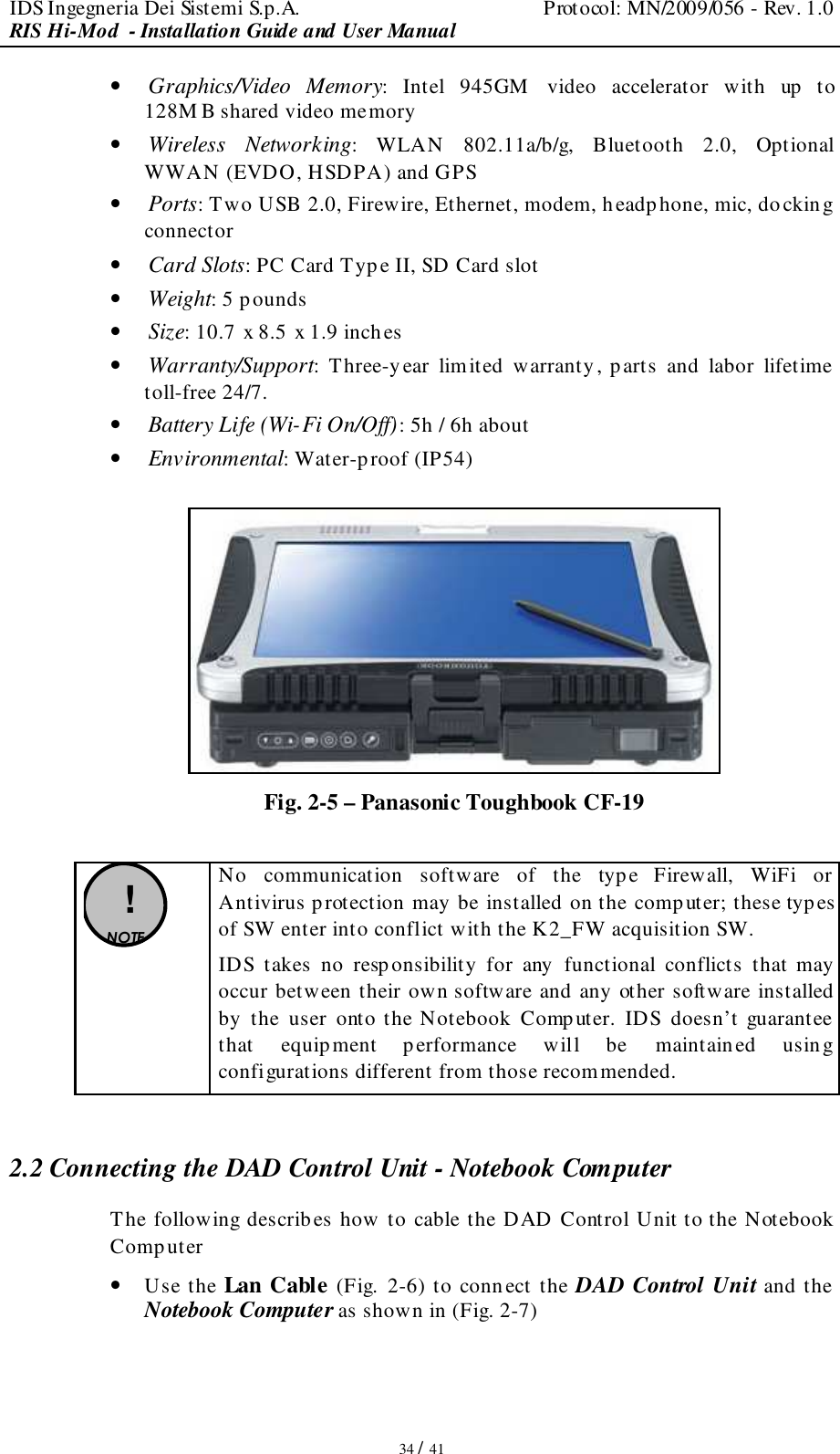
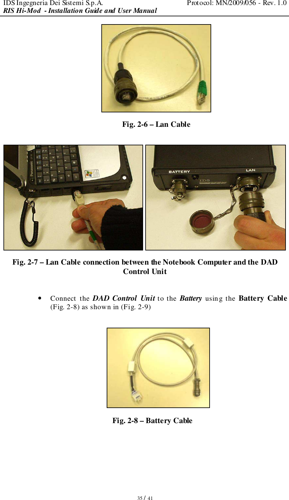
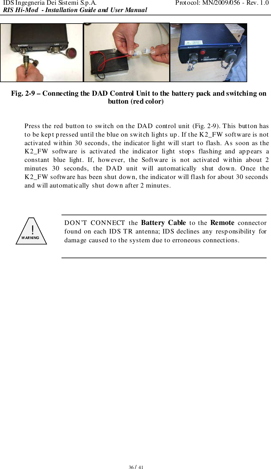
RIS Hi-Mod user manual
Navigation menu
Upload a User Manual
Namespaces
Wiki Guide
HTML
PDF
Info
Views
User Manual
Discussion / Help
Navigation