IDS GeoRadar s r l HIBRIGHT Ground penetrating radar User Manual manuale d uso
IDS Ingegneria dei Sistemi SpA Ground penetrating radar manuale d uso
UserManual.wiki
>
IDS GeoRadar s r l
>
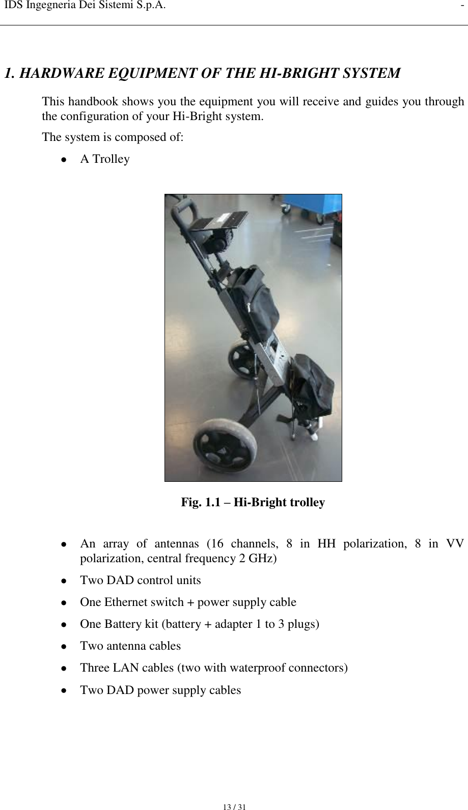
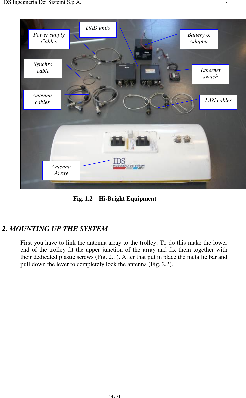
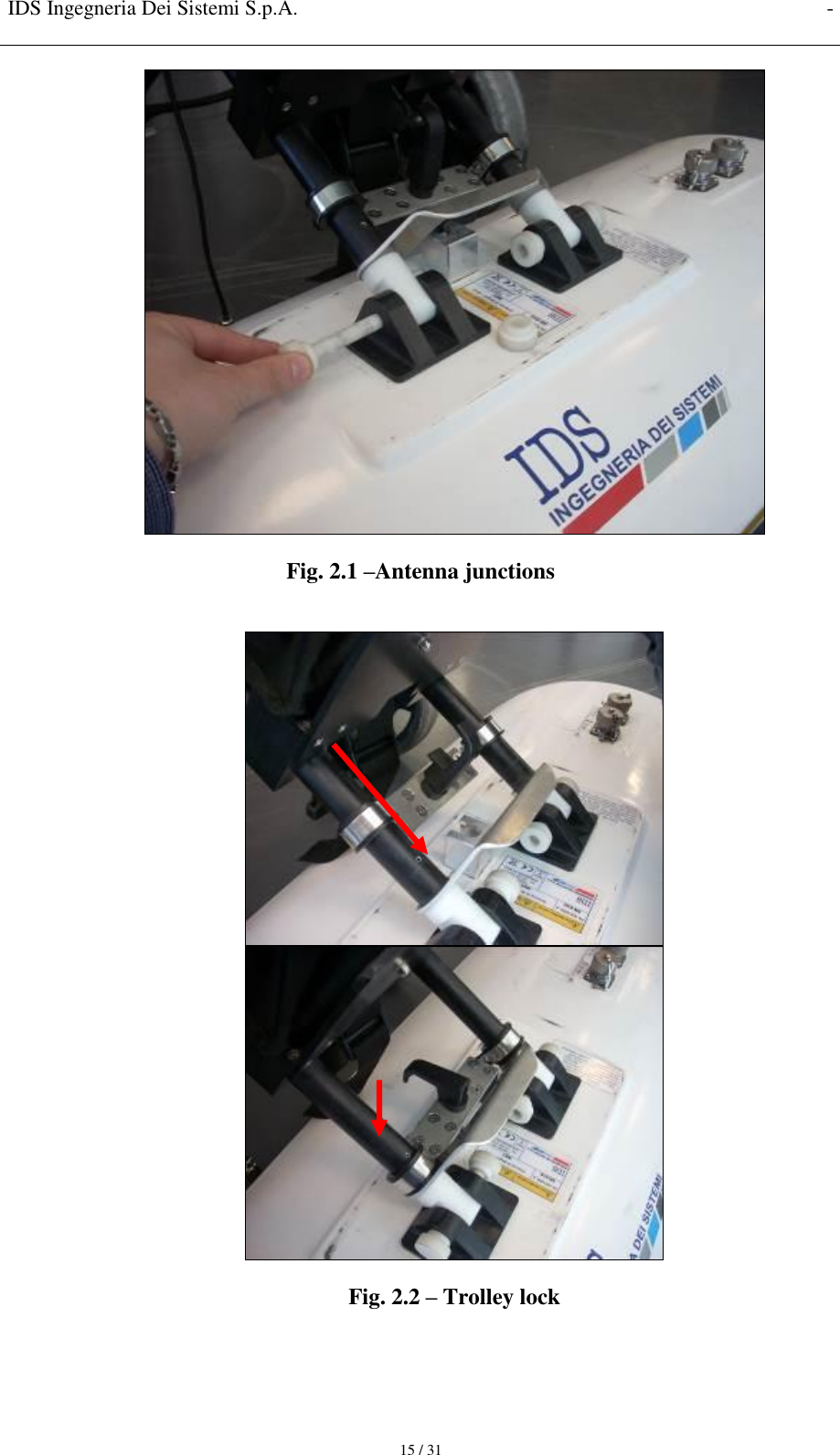
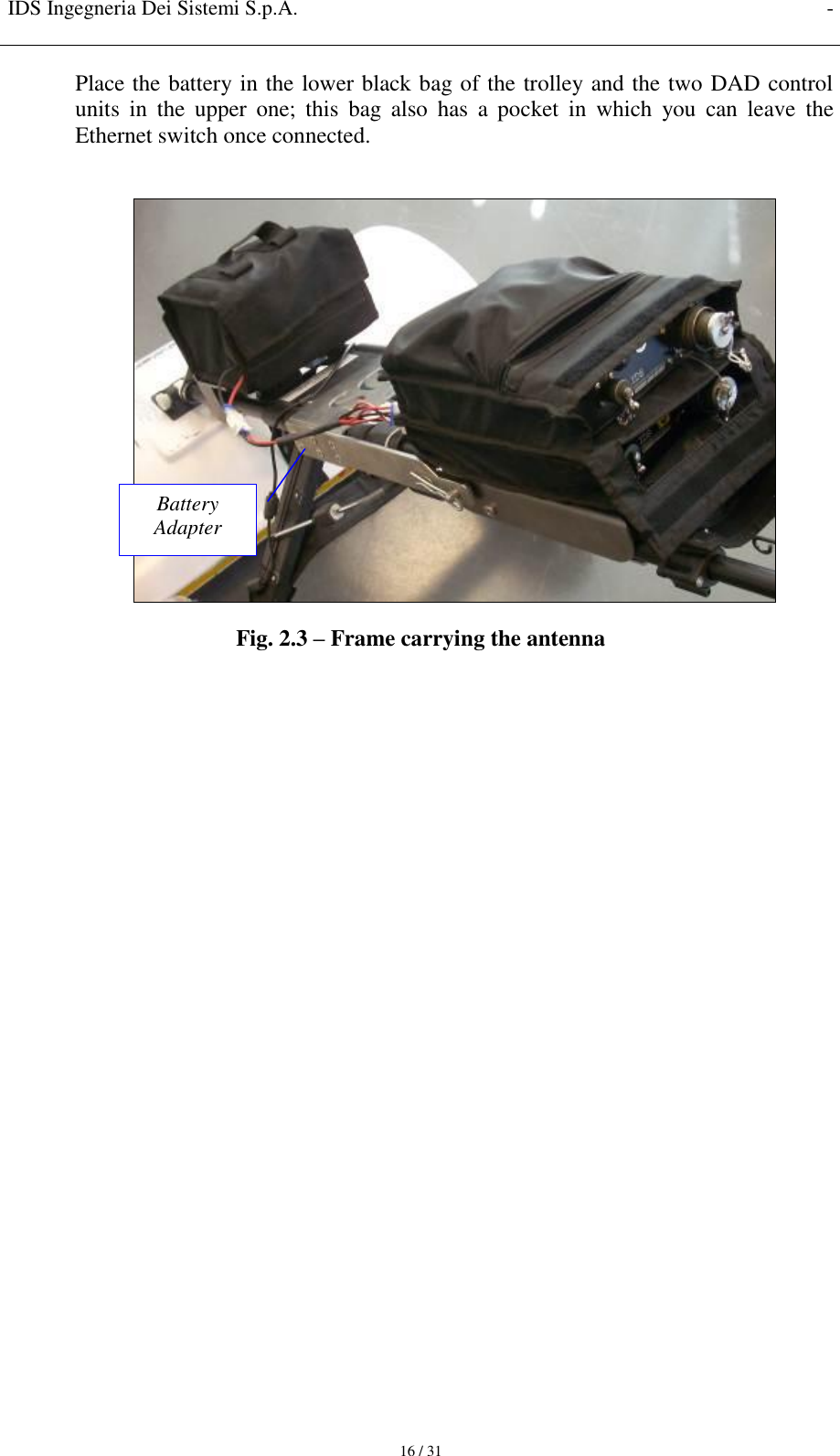
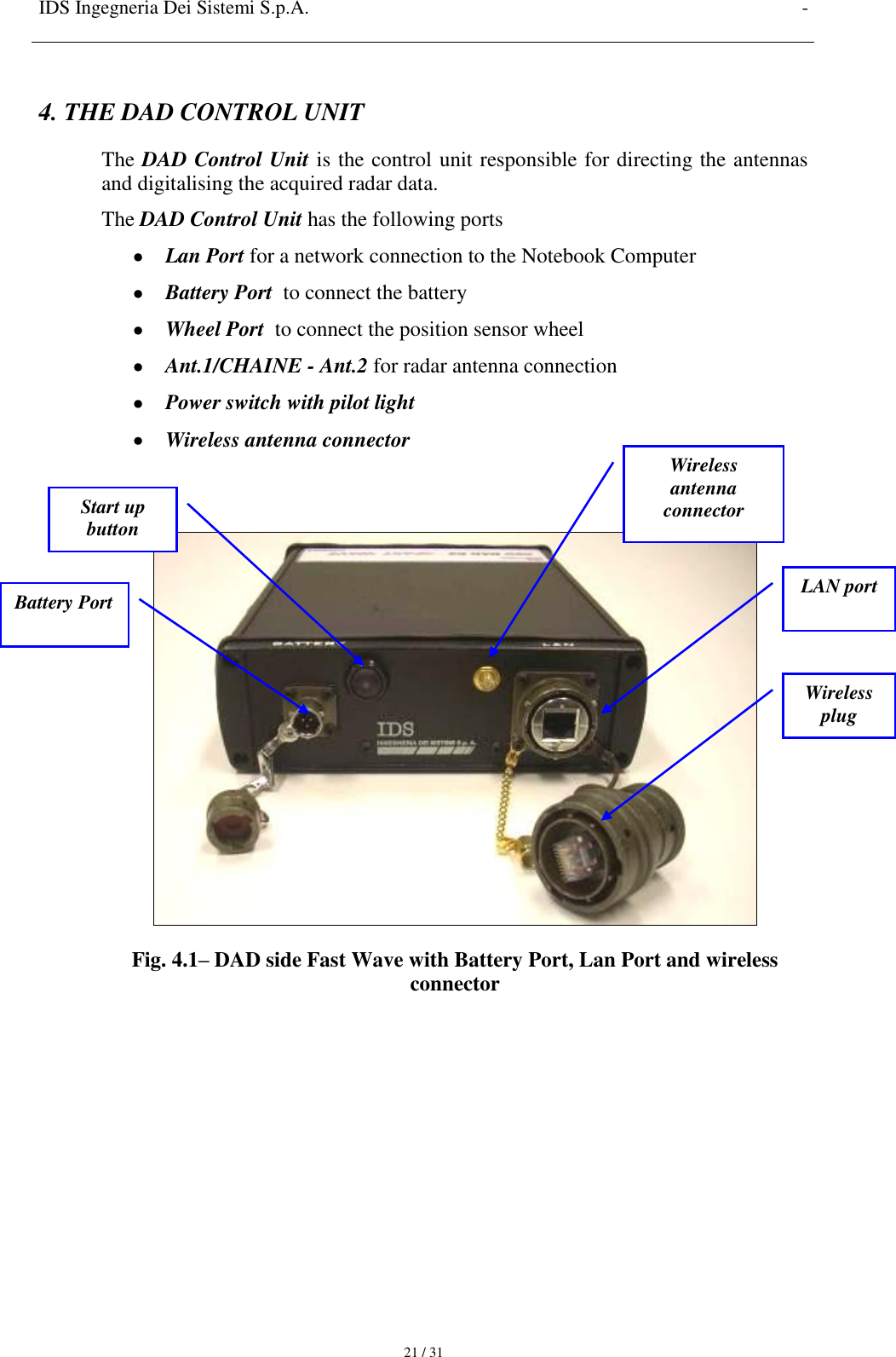
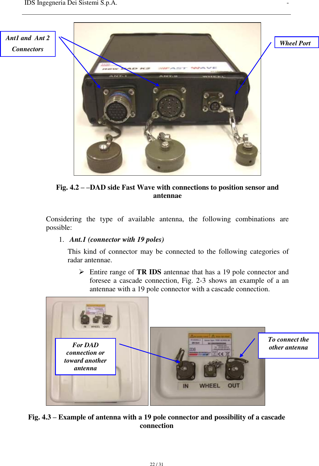
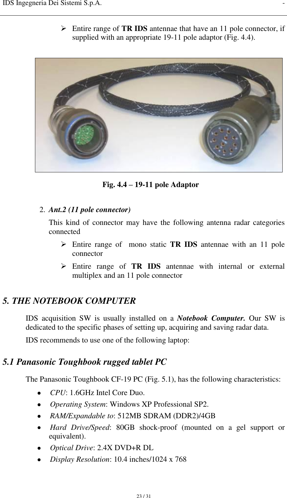
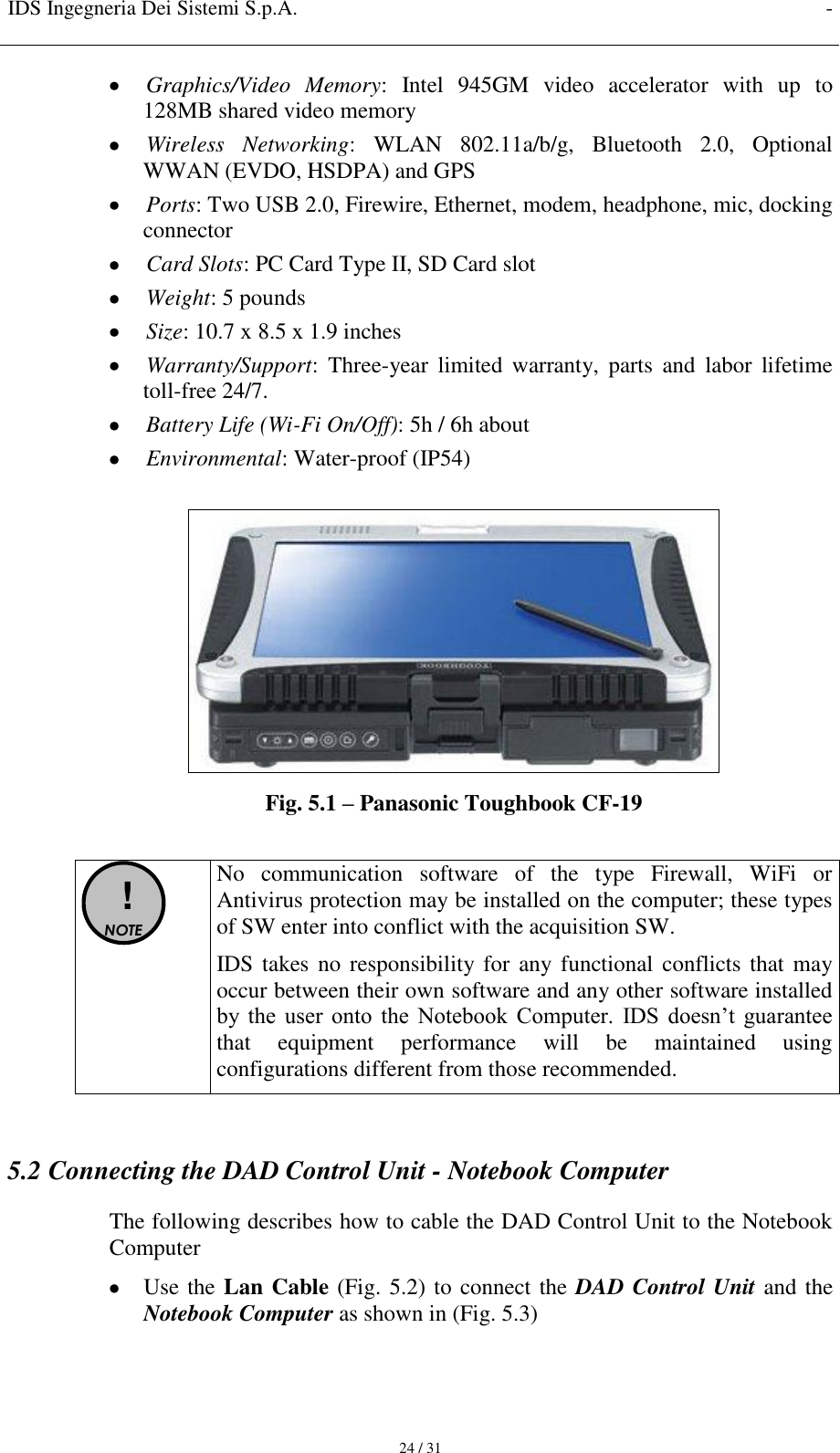
HIBRIGHT User Manual
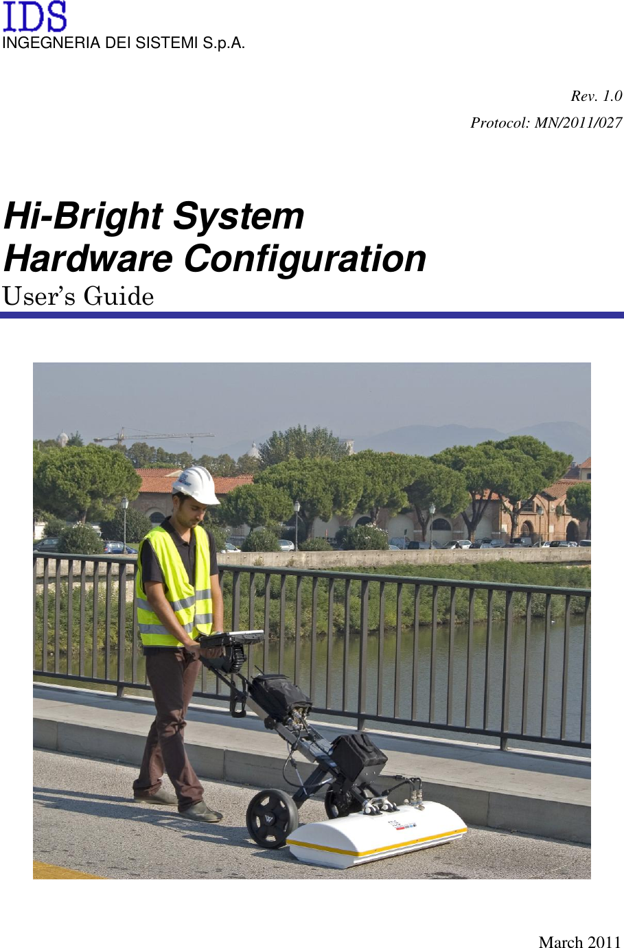
Hi-Bright HW manual mn 2011 027 rev 1.0
Navigation menu
Upload a User Manual
Namespaces
Wiki Guide
HTML
PDF
Info
Views
User Manual
Discussion / Help
Navigation