IDS GeoRadar s r l IBIS-SU IBIS Supply Unit User Manual
IDS Ingegneria dei Sistemi SpA IBIS Supply Unit
UserManual.wiki
>
IDS GeoRadar s r l
>
IBIS SU User Manual
User Manual
Navigation menu
Upload a User Manual
Namespaces
Wiki Guide
HTML
PDF
Info
Views
User Manual
Discussion / Help
Navigation


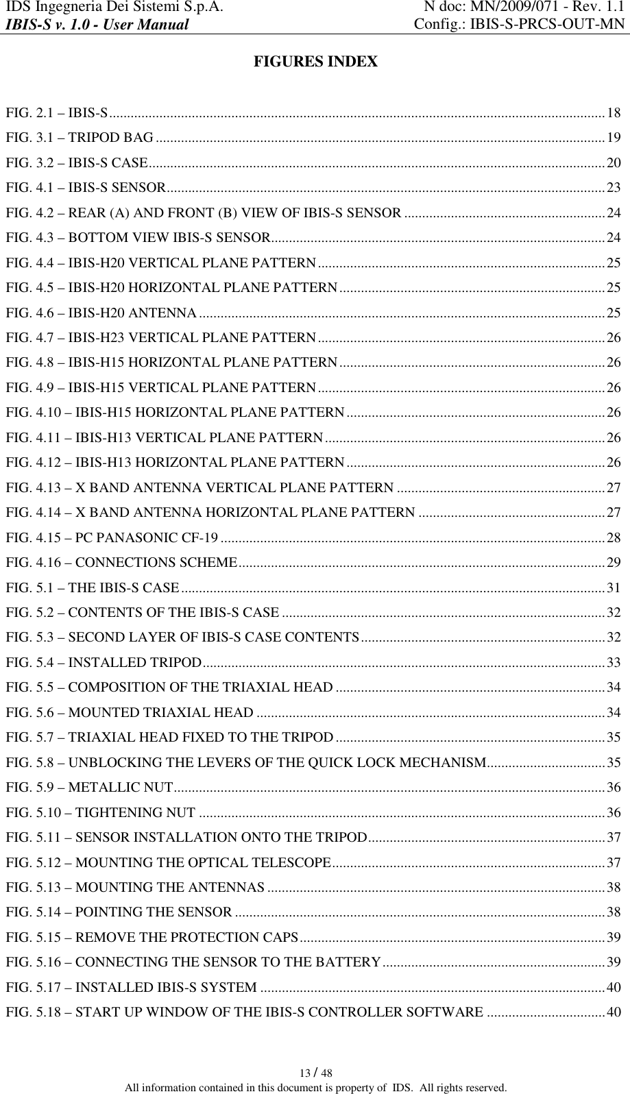
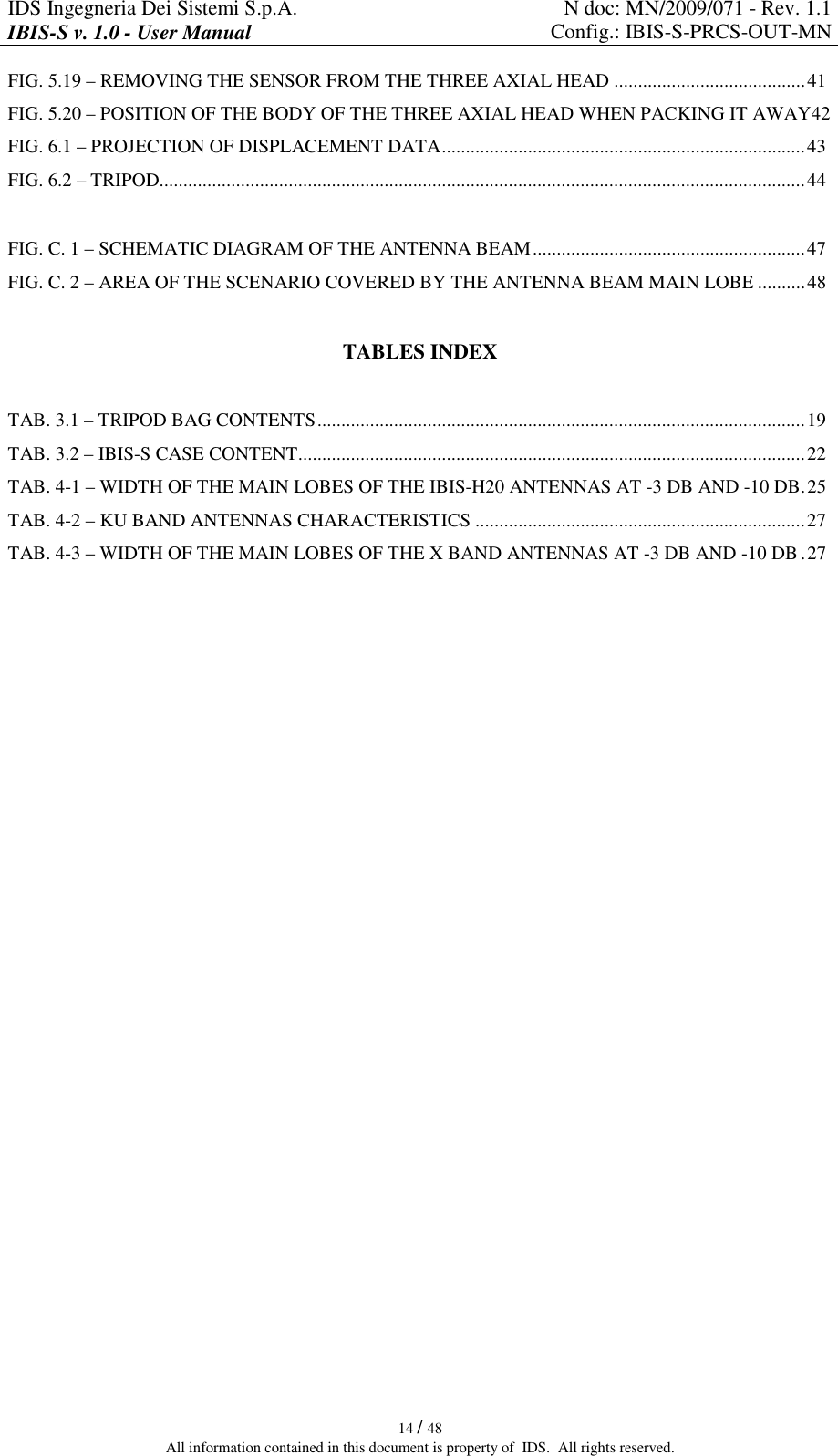
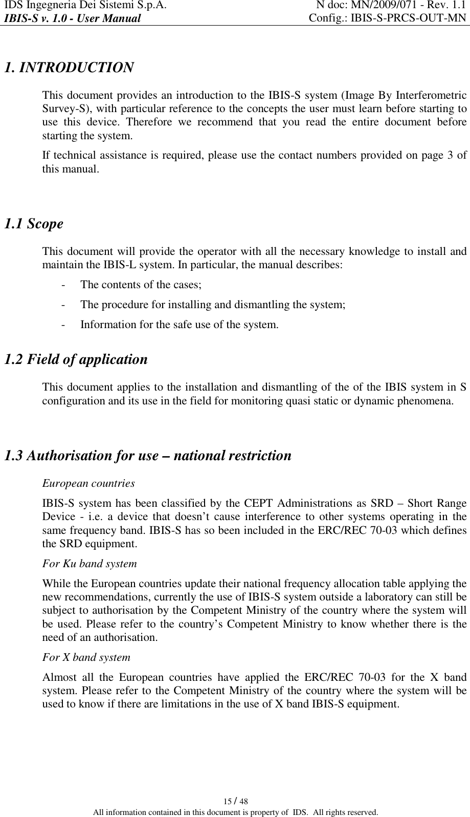
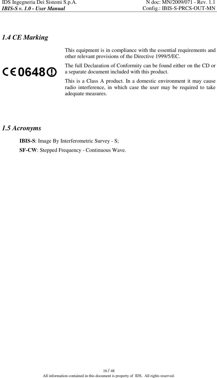
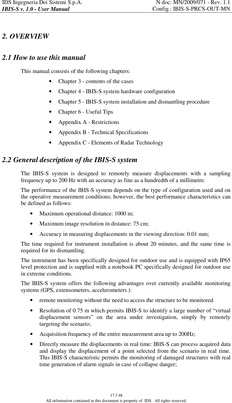
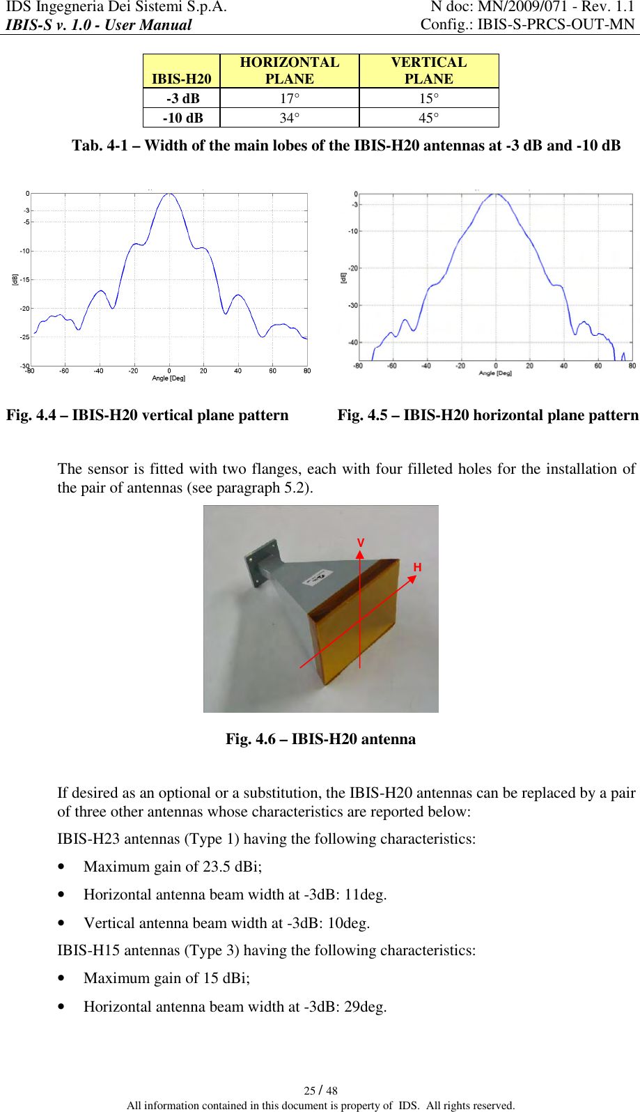
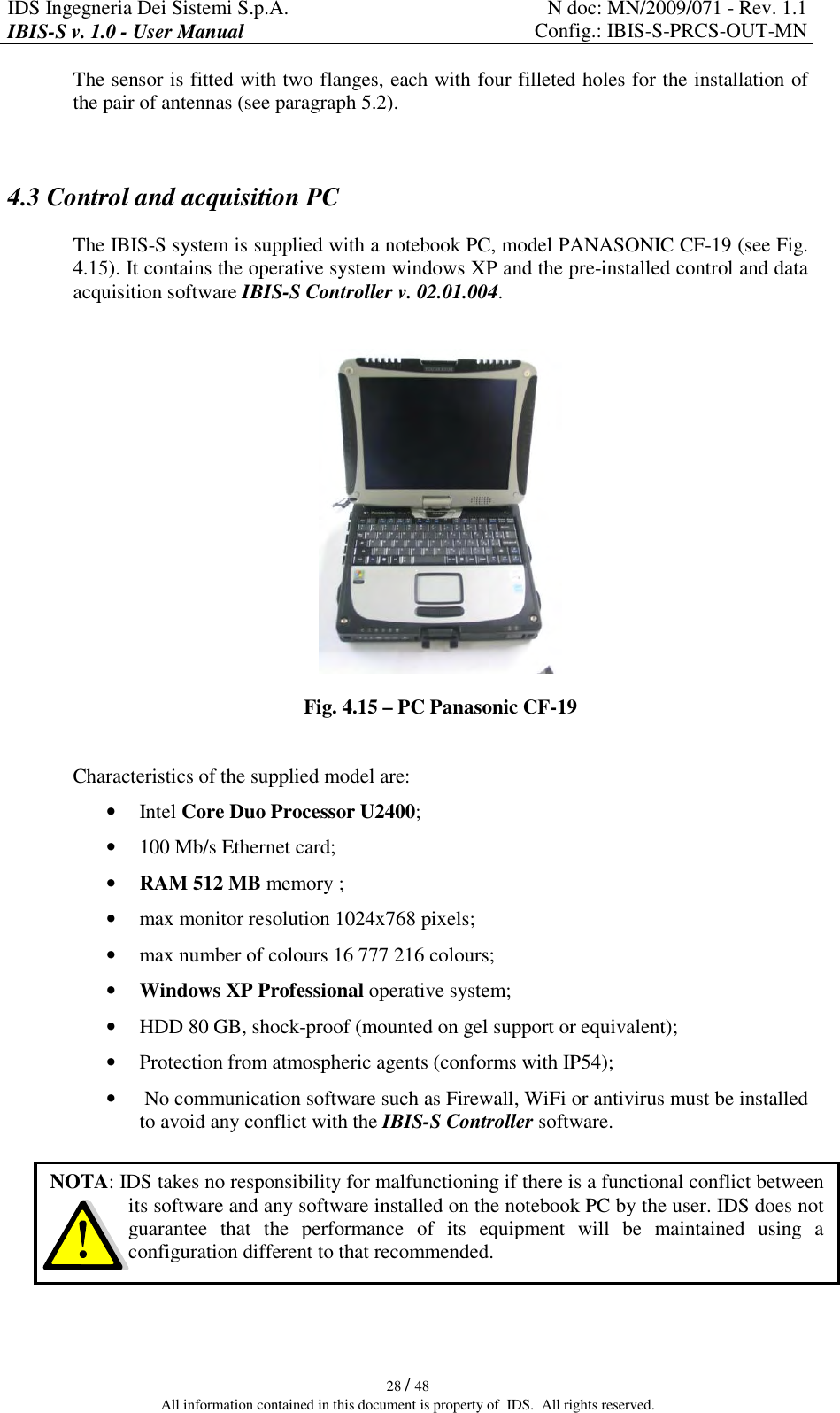
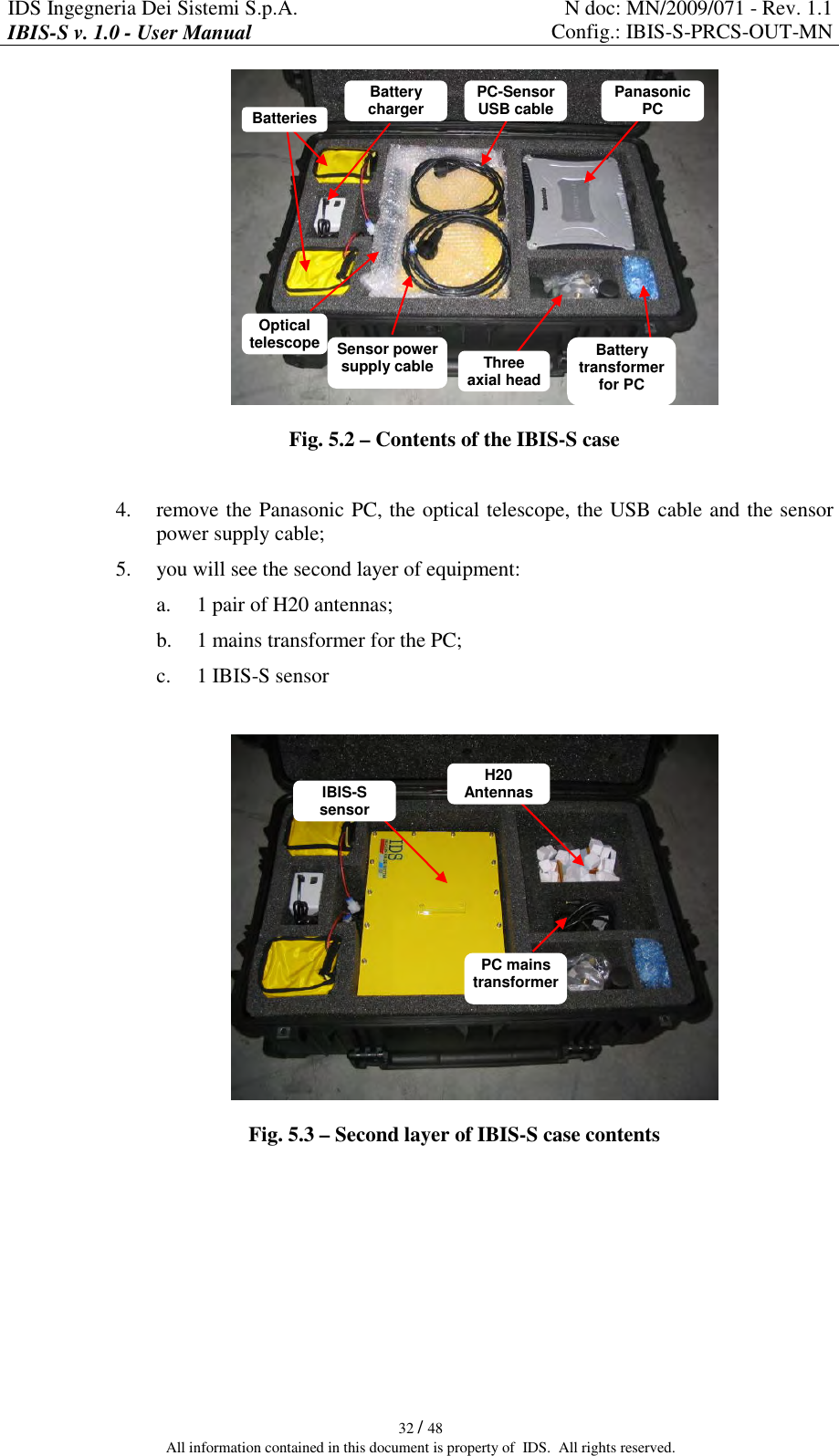
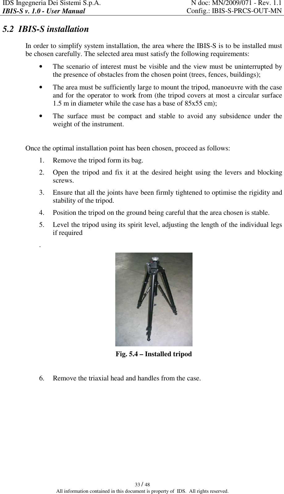
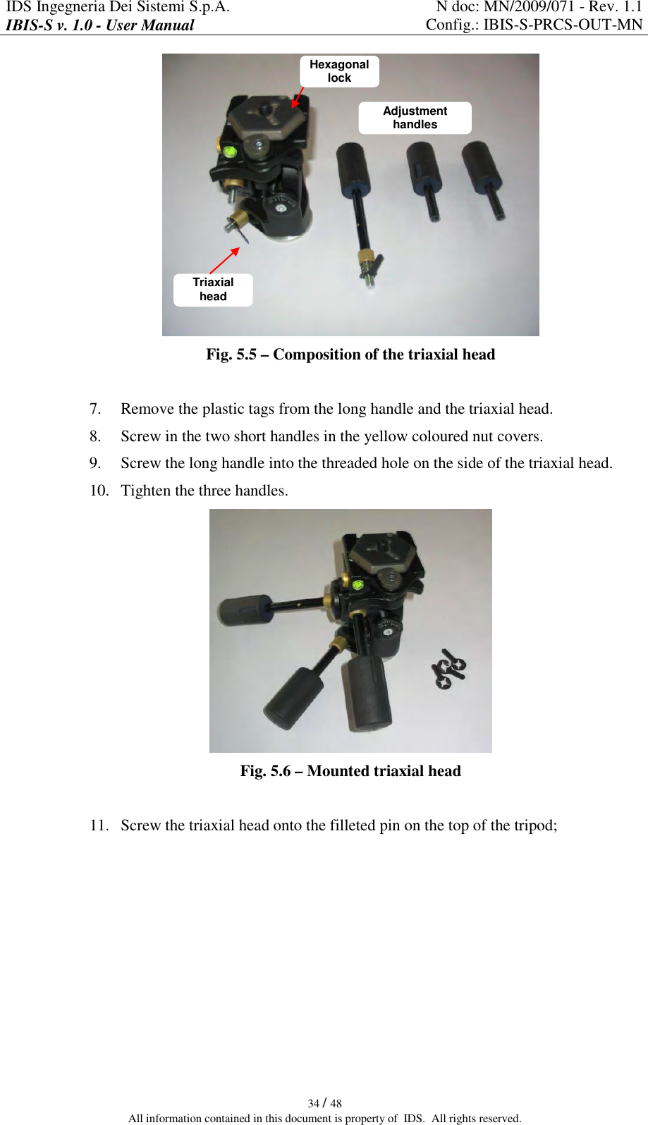
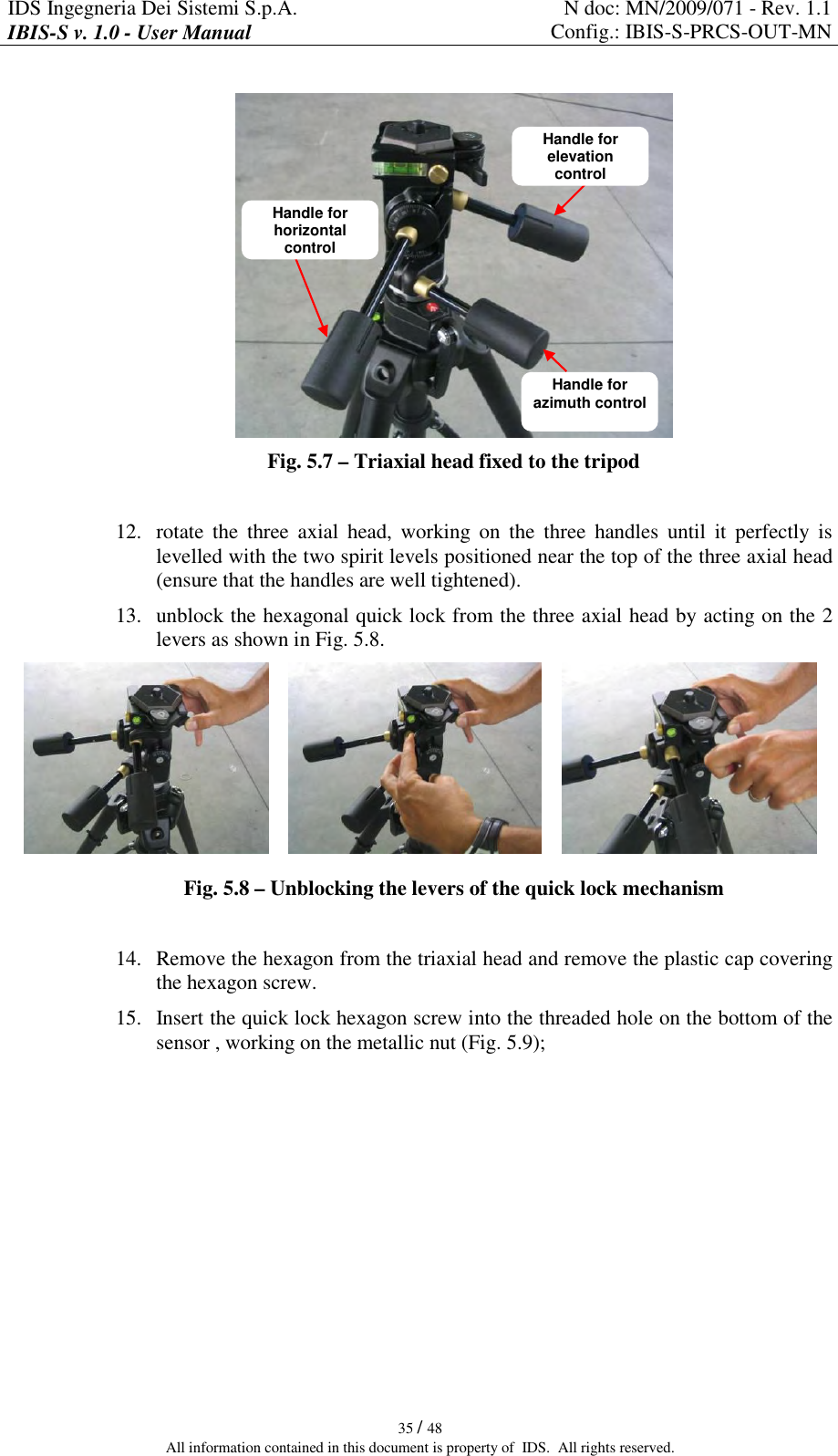
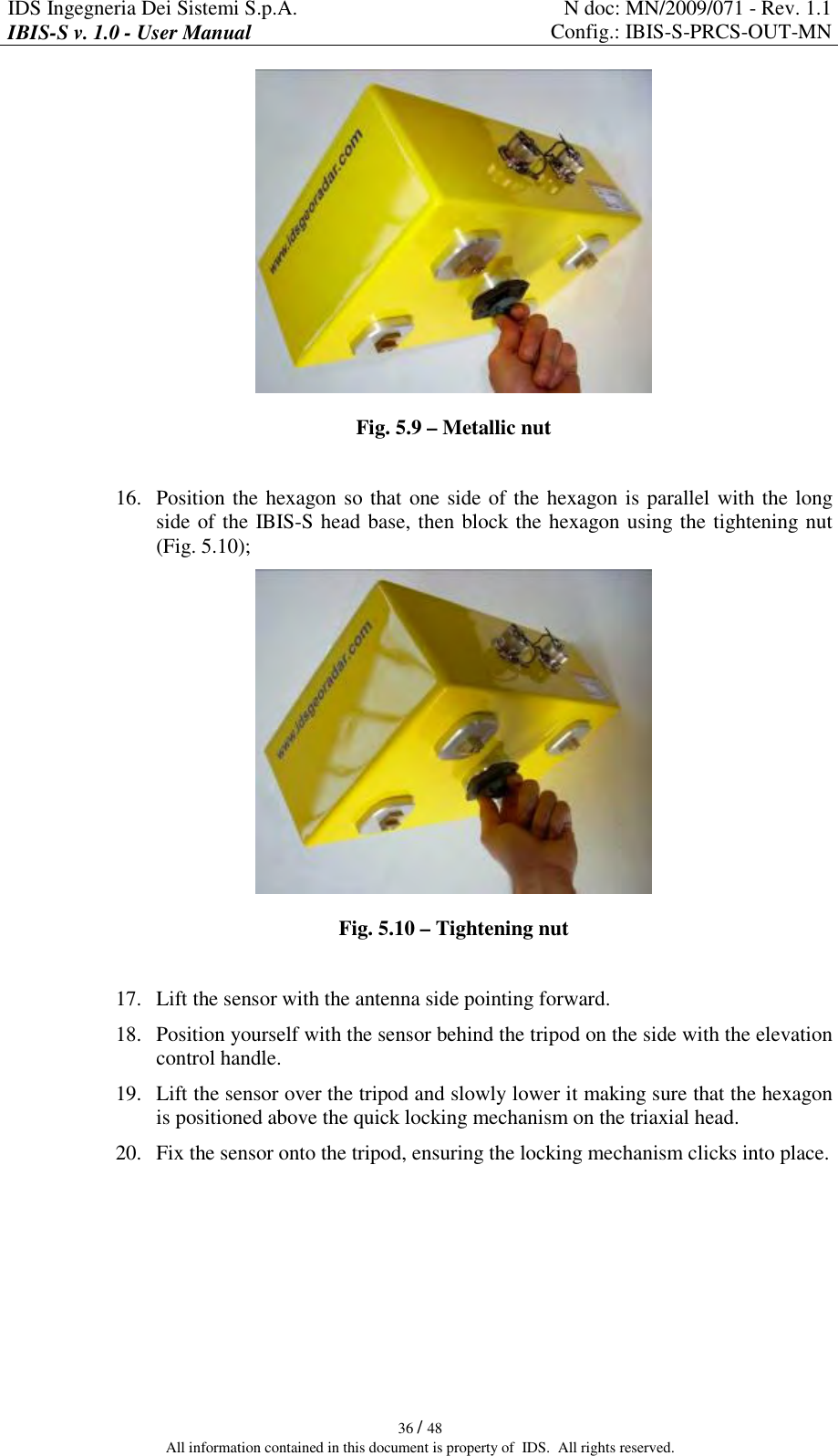
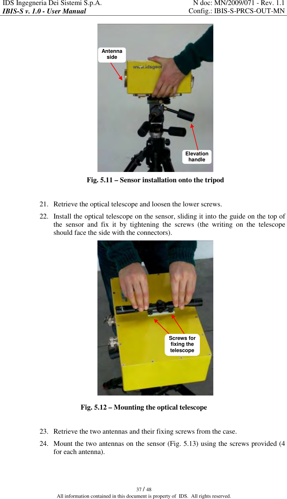
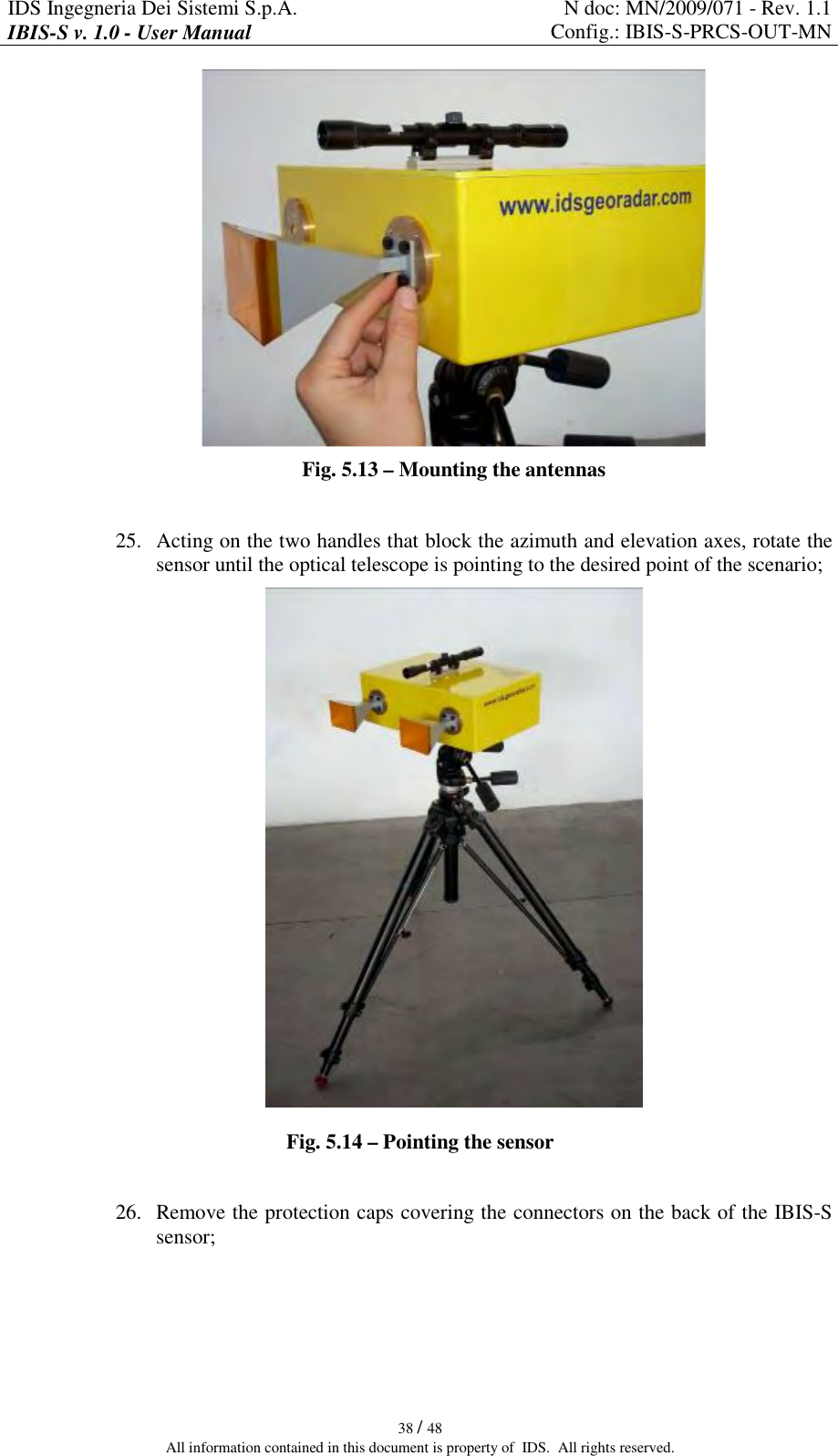
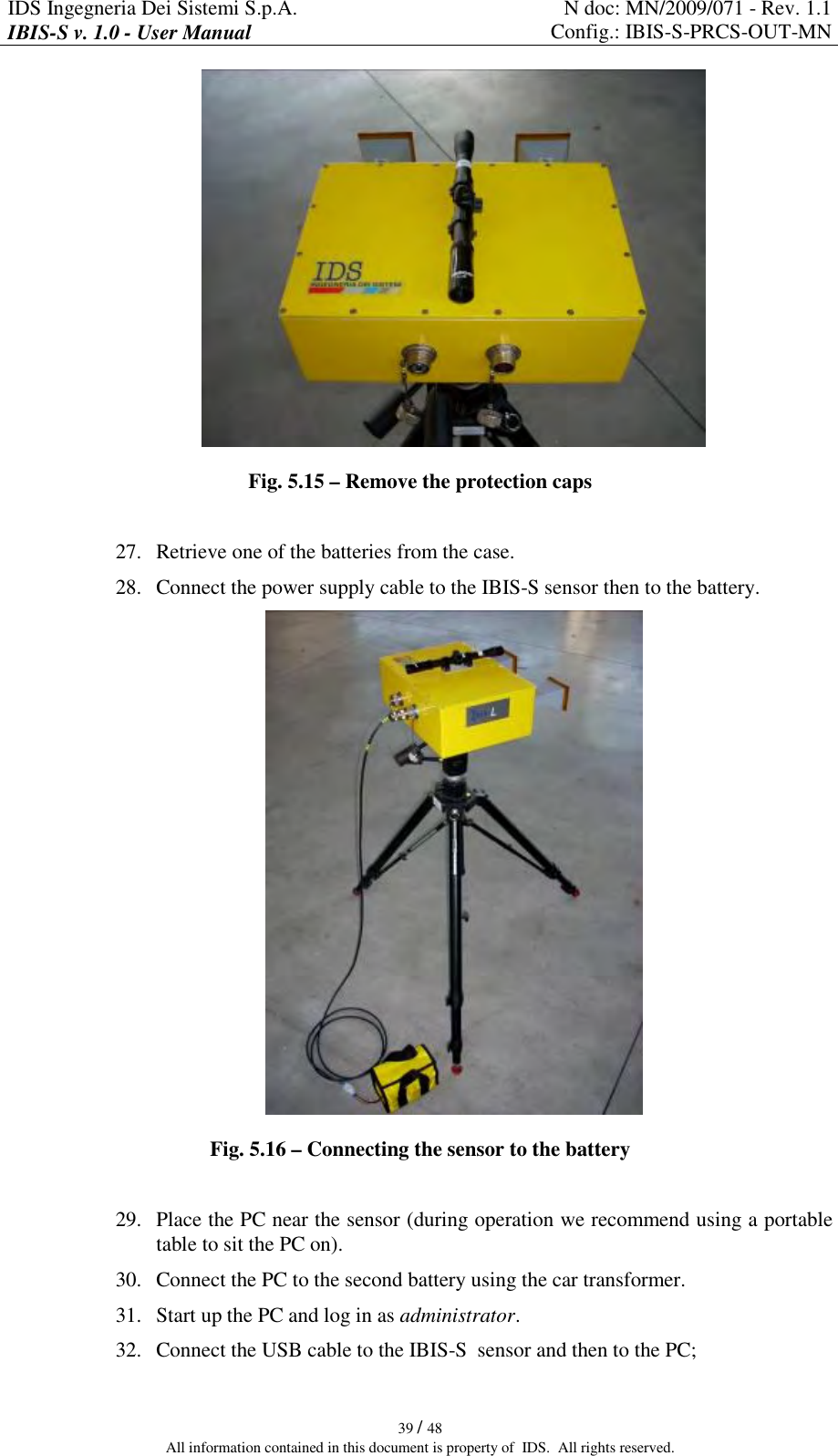
![IDS Ingegneria Dei Sistemi S.p.A. N doc: MN/2009/071 - Rev. 1.1 IBIS-S v. 1.0 - User Manual Config.: IBIS-S-PRCS-OUT-MN 27 / 48 All information contained in this document is property of IDS. All rights reserved. Gain Elevation Azimuth Antenna Type [dBi] [deg] [deg] 1 - IBIS-H23 -3 dB azimuth beamwidth 10 11 -10 dB azimuth beamwidth 23,5 30 23 2 - IBISH20 -3 dB azimuth beamwidth 15 17 -10 dB azimuth beamwidth 20 45 34 3 - IBIS-H15 -3 dB azimuth beamwidth 25 29 -10 dB azimuth beamwidth 15 49 53 4 - IBISH13 -3 dB azimuth beamwidth 18 38 -10 dB azimuth beamwidth 13,5 30 70 Tab. 4-2 – Ku band Antennas characteristics 4.2.2 X band system antennas The X band IBIS-S system is provided with two identical antennas operating in vertical polarisation and characterised by a maximum gain of 21dBi. The amplitude characteristics of the antenna main lobe at -3 dB and -10 dB are provided in Tab. 4-3 and its vertical and horizontal patterns are shown in Fig. 4.13 and Fig. 4.14. For further details see appendix 6.2C.1 - . X band antenna HORIZONTAL PLANE VERTICAL PLANE -3 dB 15° 15° -10 dB 27° 25° Tab. 4-3 – Width of the main lobes of the X band antennas at -3 dB and -10 dB Fig. 4.13 – X band antenna vertical plane pattern Fig. 4.14 – X band antenna horizontal plane pattern](https://usermanual.wiki/IDS-GeoRadar-s-r-l/IBIS-SU/User-Guide-1299763-Page-27.png)