IDS GeoRadar s r l OPERADUO Ground Penetrting Radar User Manual manuale d uso
IDS Ingegneria dei Sistemi SpA Ground Penetrting Radar manuale d uso
Users Manual
IDS Ingegneria Dei Sistemi S.p.A.
N doc:MN/2014/024 - Rev. 1.0
OPERA DUO v. 1.0 – User Manual
Config.: Opera DUO-PRCS-OUT-MN
1 / 34
All information contained in this document is property of IDS. All rights reserved
- PRO/010/M1 Rev 5 -
Rev. 1.0
N°doc:MN/2014/024
Config.: Opera DUO-PRCS-OUT-MN
OPERA DUO
OPERA
DUO
v. 1.0 – User
Manual
Pisa, February, 2014

IDS Ingegneria Dei Sistemi S.p.A.
N doc:MN/2014/024 - Rev. 1.0
OPERA DUO v. 1.0 – User Manual
2 / 34
All information contained in this document is property of IDS. All rights reserved
KEYWORDS
GEORADAR, OPERA DUO, ANTENNA, RADAR MAP
SUMMARY
This manual contains a complete description of the Opera Duo
radar system, detailing the assembly procedure, the correct use of
the data acquisition software, the field work procedure and the
general operating procedures of the system.
Document Evolution
Revision
Date
Reason of change
Rev. 1.0
First Edition
Document Change Record (Log)
RNC
Reference
Modification Description
SW Versions covered by this document
01.00.000

IDS Ingegneria Dei Sistemi S.p.A.
N doc:MN/2014/024 - Rev. 1.0
OPERA DUO v. 1.0 – User Manual
3 / 34
All information contained in this document is property of IDS. All rights reserved
DISCLAIMER
1. General.
i. The present Disclaimer applies to all products (the Products) designed, produced and distributed
by Ingegneria Dei Sistemi SpA - Georadar Division (IDS), its Subsidiaries, Affiliated and
authorized Distributors. IDS reserves full ownership and intellectual property rights of any
Information contained in this Disclaimer including Trade Marks and Graphics. No part of this
Disclaimer may be used or reproduced in any forms without the prior written agreement of IDS.
ii. In the event that any provision of this Disclaimer may be invalid, unlawful or incapable of being
enforced by a rule of law, all other provisions shall, nonetheless, remain in full force and effect.
Failure to either enforce or exercise any right, privilege, or legal remedy at any time, any
provision contained in this Disclaimer, shall not be deemed a waiver of such provisions or right,
remedy, or privilege.
iii. This Disclaimer shall be interpreted, governed, construed and enforced in accordance with the
laws of Italy. Buyer hereby consents to the exclusive jurisdiction of Pisa, Italy.
2. Initial Precautions for Setting-up and Use of the Products.
i. For setting-up and using the purchased Products, the Buyer shall consult the official
documentation provided by IDS for the Products (Reference Documentation) and carefully
ascertain the compliance with national laws and requirements, which may limit or even forbid
their use.
ii. For Products which operate by circulation in Public Areas/Roads, with or without moving traffic,
the Buyer/User shall verify the approval of local authority and/or site owner according to their
specific procedures. IDS shall not be liable for any direct, indirect, special, incidental or
consequential damages or injuries, including without limitation, lost revenues or lost profits,
resulting from unauthorized use of the Products in Public Areas/Roads.
iii. For Products which include specific Operational software with automatic data processing and
analysis Tools, the User shall be aware that the results provided by these Tools may be not error
free. Any User who completely relies on the outcomes provided by these Tools only, does it at his
own risk.
iv. In no event IDS shall be liable for special, direct, indirect, incidental, exemplary, punitive or
consequential damages including, but not limited to, loss of profits or revenue, caused by the use
of the Products, either separately or in combination with other products or relied upon the results
provided by the above Tools.
3. Disclaimer for the Use of the Products.
i. The User shall follow the instructions provided by IDS in its official Reference Documentation
for the Product, in particular the User’s Technical Manual which contains all the specific steps
and recommendations for a correct set-up and use of the Product.
ii. In no event IDS shall be liable for special, direct, indirect, incidental, exemplary, punitive or
consequential damages including, but not limited to, loss of profits or revenue, caused by the lack
or incomplete observance of the instructions and prescriptions for the use of the Products, either
separately or in combination with other products, in particular for the following main aspects:
a. Use of IDS Products outside their limitation of use, without proper and adequate
scientific/technical knowledge or without specific training.
b. Use of results/outcomes of the measurements performed by the Product dealing with
safety aspects without using adequate control procedures and assessment by skilled
personnel.
c. Opening of the Equipment (for HW Products) without express written authorization from
IDS.
d. Unauthorized changes and additions to the Products.
e. Use of the Products connected to suspected defective equipment or to equipment (mainly
PC) not having characteristics in compliance with the required IDS specifications or not
expressly authorized by IDS.
f. Poor or faulty operation of the electrical and telecommunication networks not directly
managed by IDS or its delegates.
g. Poor or faulty operation of third party Software/Hardware connected with IDS
Equipment.
Rev. 1.0

IDS Ingegneria Dei Sistemi S.p.A.
N doc:MN/2014/024 - Rev. 1.0
OPERA DUO v. 1.0 – User Manual
4 / 34
All information contained in this document is property of IDS. All rights reserved
h. Poor or faulty operation of the Products due to infection from Software Virus after their
delivery.
i. Use of the Products which have encountered suspected manumissions, accidents,
electrostatic shocks, lightning, fire, earthquake, flooding or other natural disasters or
unexpected events.
j. Use or storage of the Products outside the limits of the Operational Temperature Range
specified by IDS.
Contacts
IDS Ingegneria dei Sistemi S.p.A. – GeoRadar Division
Via Enrica Calabresi, 24 – Loc. Montacchiello
56121 PISA - ITALY
Tel: +39.050.312411
Fax: +39.050.3124205
inforis@idscorporation.com
Customer Care department:
customercare.gpr@idscorporation.com
Tel.: +39.050.3124356
Sales & Marketing department:
sales.gpr@idscorporation.com
Tel.: +39.050.3124352

IDS Ingegneria Dei Sistemi S.p.A.
N doc:MN/2014/024 - Rev. 1.0
OPERA DUO v. 1.0 – User Manual
5 / 34
All information contained in this document is property of IDS. All rights reserved
Warranty Conditions & Registration Form
A. Standard Warranty Conditions
1. IDS Ingegneria dei Sistemi S.p.A, (hereinafter referred to as IDS or Seller), warrants that its products shall be free from defects in material
and workmanship, for a period of 12 months from the delivery date duly registered and certified (“Effective Date”) in the “Warranty
Registration Form” enclosed hereto. IDS shall repair or replace Products or parts thereof found faulty (the “Faulty Parts”) which are returned
to IDS, and which, at IDS’s judgment, were defective or became defective during its normal use. The Seller’s obligations shall not apply to
Faulty Parts that:
(a) The Buyer does not properly store, install, use, or maintain;
(b) The Buyer modifies, or performs tests on, which are not approved in writing by the Seller;
(c) The Buyer has subjected to any kind of misuse, detrimental exposure beyond its intended purpose or damaged in an accident or by
natural disaster or calamities.
(d) Are repaired by personnel other than IDS personnel; in which HW/SW accessories not supplied by IDS have been installed; are
integrated or connected to equipment different from the ones supplied by IDS (except the PC data Logger conform to IDS
specifications);
(e) Whose operational software was not installed as per IDS instructions (see IDS User’s Guide for the Data Acquisition Software);
2. The Seller’s Products may include specific “Operational” software with automatic data processing and analysis tools (SW) supplied under a
License agreement (EULA). While every effort is made to ensure the accuracy of the information/results provided by these tools, they must
not be intended as a substitute for analysis by personnel; rather, they are intended as an advisor and the user must not completely rely on the
results provided by them. Under no circumstances does IDS warrant that the SW will operate uninterrupted or error free. The SW is provided
“as is” without warranty of any kind. IDS warrants for a period of sixty (60) days from the Effective date that, under normal use, the SW
support media will be free of defects in material and workmanship; in such case the provisions of above point a) apply
3. Any different warranty, granted by the Buyer to its retailers and clients, even as final consumers, pursuant to the European Union law in
force regarding the rights of the consumers, does not engage IDS in anyway.
4. The above mentioned warranty excludes any other remedies and it has to be considered the only and exclusive remedy foreseen for the Buyer
and its retailers and clients, with reference to IDS Products purchase, being, expressively understood that any kind of limitation and/or
discharge of responsibility provided by the present warranty is referred to both (I) the responsibility as against any third parties, pursuant to
the legislation regarding the producer responsibility and (II) the warranty provided by the law in force.
B. Warranty Procedure
1. To proceed in the application of warranty terms, the Buyer has to contact IDS Customer Care Office to get the clearance to return the Faulty
Parts.
2. The Faulty Parts once received by IDS will be inspected to verify they are eligible for repair or replacement..
3. The Buyer is responsible for ensuring that the Faulty Parts are returned to IDS in suitable packing (it is recommended that the original
packing be saved for a better understand of the failure cause); IDS will not be obliged to repair or replace Faulty Parts damaged from abuse,
misuse, negligence, accident loss or damage in transit.
4. The Shipping costs for Products returned during the warranty period, are as follows:
(f) From the Buyer Site to the Seller site shipping costs, as per Incoterms CIP, are borne by the Buyer
(g) From the Seller Site to the Buyer site shipping cost, as per Incoterms CIP, are borne by the Seller
5. The warranty period on the repaired or replaced Faulty Parts is 6 (six) months or the unexpired portion of warranty on such Faulty Parts
whichever date comes later.
C. Limited Liability
1. The Seller’s sole obligation and liability under this Agreement shall be limited to the repair or replacement of the Product, or the refund of
the purchase price at the Seller’s sole option. This Article sets forth the sole and exclusive remedies for claims based upon defects or
nonconformity of the Products, whether the claim is on contract, warranty, tort (including negligence), strict liability, or otherwise.
2. The cumulative liability of the Seller, including its subcontractors or suppliers, for any and all claims, including but not limited to claims
based on the Seller’s negligence of any degree, strict liability, breach of contract, warranty, reliance on the accuracy, reliability, or timeliness
of the information provided by the SW, patents or otherwise, shall not exceed the sums cashed by IDS for the purchased Products, which
give rise to the claim, and any such liability shall terminate upon the expiration of the warranty period.

IDS Ingegneria Dei Sistemi S.p.A.
N doc:MN/2014/024 - Rev. 1.0
OPERA DUO v. 1.0 – User Manual
6 / 34
All information contained in this document is property of IDS. All rights reserved
Registration Form
(to be partially filled in by IDS, sent to Distributor/Customer and returned to IDS duly completed as indicated)
To be filled in by
References and dates
Distributor Purchase Order (if applicable)
IDS
End Customer Purchase Order (if available)
Distributor/IDS
Delivery Date certified by IDS
IDS
Effective Date certified for Warranty (*)
Distributor/End
Customer
Distributor Name (if applicable)
IDS
End Customer Name and full address
Distributor/IDS
End Customer Representative (Name, Phone,
Fax, e-mail address)
End Customer
IDS seal and signature
Distributor seal and signature (if applicable)
End Customer seal and signature
List of Products purchased and test certificate to be filled in by IDS (if the lines are not enough, please use additional sheet)
Order
line
item
Description
Q.ty
S/N
System Summary
Test Certificate date and
reference to internal test
report(**)
(*) In case the Customer/Distributor does not return the Warranty Registration Form duly filled in and signed to IDS the effective
warranty date shall start 10 (ten) days after the delivery date as certified by IDS and written in the above form.

IDS Ingegneria Dei Sistemi S.p.A.
N doc:MN/2014/024 - Rev. 1.0
OPERA DUO v. 1.0 – User Manual
7 / 34
All information contained in this document is property of IDS. All rights reserved
(**) By inserting a date in this field, IDS certifies that the item has been checked and calibrated as per IDS standard procedures and the
item meets or exceeds all test specifications. The location of tests is Pisa – Italy.
!
WARNING
CLEANING INFORMATION
Before cleaning any external parts of the apparatus, make sure
that all cables have been disconnected, including the power
supply cable. If a damp cloth is used, make sure it is not too wet,
to avoid any damage to the electrical components of the
equipment. Wait until the equipment is totally dry before
reconnecting the cables.
The Opera Duo should be cleaned periodically using a damp
cloth.
Do not use solvents or abrasive detergents.
Do not apply liquid directly to the electrical contacts of the
various connectors. If a specific spray is used to clean the PC
TFT monitor, make sure it is not flammable; in any case, do not
spray it directly on the screen, instead, spray it onto the cleaning
cloth.
IDS Ingegneria Dei Sistemi S.p.A.
N doc:MN/2014/024 - Rev. 1.0
OPERA DUO v. 1.0 – User Manual
8 / 34
All information contained in this document is property of IDS. All rights reserved
BATTERIES REMOVAL INFORMATION
Laptop Batteries (X2):
Type: Li-ion
Characteristics: 7.2 V 3.4 Ah
Removal instructions:
1. Open the drawer with the symbol of the batteries;
2. Extract the battery pack pulling the tab.
Radar batteries:
Manufacturer: FIAMM FG21202 / SAFT MP176065
Type: Rechargeable lead acid / rechargeable lithium-ion
Characteristics: 12V & 12Ah / 15V & 6.8Ah
Removal instructions:
1. Disconnect the battery from the instrument:
a. pull the connector wings;
b. separate the connectors;
2. Remove the battery from the cover (optional) opening the
strap.

IDS Ingegneria Dei Sistemi S.p.A.
N doc:MN/2014/024 - Rev. 1.0
OPERA DUO v. 1.0 – User Manual
9 / 34
All information contained in this document is property of IDS. All rights reserved
RECYCLING
The crossed out wheeled bin symbol shown on the equipment indicates that
the product must be recycled separately from other waste at the end of its
useful life.
Separate waste disposal of this product at the end of its useful life will be
organised and managed by IDS. When you decide to dispose of the
equipment, contact IDS and follow the system that IDS has set up to permit
the separate collection of the apparatus at its life end.
Adequate separate collection for its subsequent recycling, treatment and
environmental friendly disposal contribute towards avoiding any
unnecessary effects on the environment and to health and favour the reuse or
recycling of the materials that make up the equipment. Unauthorised disposal
of this product as unsorted waste by its possessor will lead to an
administrative penalty foreseen by national regulations.

IDS Ingegneria Dei Sistemi S.p.A.
N doc:MN/2014/024 - Rev. 1.0
OPERA DUO v. 1.0 – User Manual
10 / 34
All information contained in this document is property of IDS. All rights reserved
CONTENTS
1. Introduction ........................................................................................................................... 12
1.1 Purpose .......................................................................................................................... 12
1.2 Application Field ........................................................................................................... 12
1.3 Trademarks .................................................................................................................... 12
1.4 Reference ....................................................................................................................... 12
1.4.1 Regulations ..................................................................................................................... 12
1.5 Acronyms and Definitions .............................................................................................. 15
1.5.1 Acronyms ....................................................................................................................... 15
1.5.2 Definitions ...................................................................................................................... 15
2. Overview................................................................................................................................. 16
2.1 Contents ......................................................................................................................... 16
2.2 Intended readership ....................................................................................................... 16
3. Opera Duo hardware description ........................................................................................ 17
3.1 Opera Duo main body ................................................................................................... 17
3.1.1 Antenna .......................................................................................................................... 17
3.1.2 Control unit .................................................................................................................... 18
3.1.3 Encoders ......................................................................................................................... 18
3.1.4 Handle ............................................................................................................................ 19
3.1.5 Wheels ............................................................................................................................ 20
3.1.6 Laptop support ............................................................................................................... 20
3.2 Laptop ............................................................................................................................ 21
3.3 Battery ........................................................................................................................... 22
3.4 Battery charger .............................................................................................................. 23
3.5 Spray support ................................................................................................................. 24
3.6 GPS support ................................................................................................................... 25
4. Assembly procedure .............................................................................................................. 26
4.1 Unfold the radar main body .......................................................................................... 26
4.2 Connect the laptop ......................................................................................................... 29
4.3 Insert the battery ............................................................................................................ 30
4.4 Mount the Spray support ............................................................................................... 31
4.5 Mount the GPS support ................................................................................................. 33
4.6 Encoder calibration ....................................................................................................... 34
FIGURES INDEX
FIG. 3.1 – DAD POWER BUTTON ............................................................................................................ 18

IDS Ingegneria Dei Sistemi S.p.A.
N doc:MN/2014/024 - Rev. 1.0
OPERA DUO v. 1.0 – User Manual
11 / 34
All information contained in this document is property of IDS. All rights reserved
FIG. 3.2 – OPERA DUO HANDLE ............................................................................................................. 19
FIG. 3.3 – ETHERNET CABLE PLUG ON THE HANDLE ...................................................................... 19
FIG. 3.4 – TWO AND FOUR WHEELED VERSIONS OF THE OPERA DUO ........................................ 20
FIG. 3.5 – LAPTOP SUPPORT ................................................................................................................... 20
FIG. 3.6 – PANASONIC CF-H2 .................................................................................................................. 21
FIG. 3.7 – OPERA DUO BATTERY ........................................................................................................... 22
FIG. 3.8 – BATTERY CHARGER ............................................................................................................... 23
FIG. 3.9 – SPRAY SUPPORT ...................................................................................................................... 24
FIG. 3.10 – EXAMPLE OF VERTICAL SPRAY SPOT MARKER ........................................................... 24
FIG. 3.11 – SPRAY SUPPORT STORAGE BAG ....................................................................................... 25
FIG. 3.12 – GPS SUPPORT IN THE STORAGE BAG ............................................................................... 25
FIG. 4.1 – UNFOLD THE OPERA DUO .................................................................................................... 26
FIG. 4.2 – HANDLE BAR AND LAPTOP SUPPORT HEIGHT REGULATION BUTTONS .................. 27
FIG. 4.3 – LAPTOP SUPPORT INCLINATION REGULATION .............................................................. 27
FIG. 4.4 – ANTENNA LOCKING LEVER FOR TWO WHEELED VERSION ........................................ 28
FIG. 4.5 – ANTENNA HEIGHT REGULATION ....................................................................................... 28
FIG. 4.6 – VELCRO STRIPS ON THE LAPTOP AND LAPTOP SUPPORT............................................ 29
FIG. 4.7 – ETHERNET CONNECTION...................................................................................................... 29
FIG. 4.8 – BATTERY COMPARTMENT ................................................................................................... 30
FIG. 4.9 – BATTERY CONNECTION ........................................................................................................ 30
FIG. 4.10 – SPRAY SUPPORT LOCKS ...................................................................................................... 31
FIG. 4.11 – SPRAY SUPPORT FIXING ..................................................................................................... 31
FIG. 4.12 – SPRAY SUPPORT CABLE CONNECTION ........................................................................... 32
FIG. 4.13 – SPRAY CAN INSERTION ....................................................................................................... 32
FIG. 4.14 – GPS SUPPORT UPPER PART INSERTION ........................................................................... 33
FIG. 4.15 – GPS SUPPORT LOWER PART FIXING ................................................................................ 33

IDS Ingegneria Dei Sistemi S.p.A.
N doc:MN/2014/024 - Rev. 1.0
OPERA DUO v. 1.0 – User Manual
12 / 34
All information contained in this document is property of IDS. All rights reserved
1. INTRODUCTION
1.1 Purpose
This manual explains how to use an Opera Duo system.
1.2 Application Field
This system is dedicated to underground utilities localization and mapping and it is used
for applications in the civil engineering field.
1.3 Trademarks
Windows 7 and Windows 8 are owned by the Microsoft Corporation.
Google is owned by Google Inc.
1.4 Reference
The applicable versions of the following documents are the ones officially released at the
time of the emission of the present document.
1.4.1 Regulations
CONFORMITY TO EUROPEAN REGULATIONS
The equipment conforms to the following requirements set by EC
regulations, including subsequent modifications, and to the legislation set
by the member states that implement these regulations:
1999/05/EEC Radio Directive
Warning: this equipment is destined for use in industrial environments
(Class A apparatus). In residential, commercial and light industry
environments, this apparatus may generate radio interference: in this case,
the user may be required to operate while taking appropriate
countermeasures.
The apparatus is sensitive to the presence of external electromagnetic fields,
which may reduce its performance.

IDS Ingegneria Dei Sistemi S.p.A.
N doc:MN/2014/024 - Rev. 1.0
OPERA DUO v. 1.0 – User Manual
13 / 34
All information contained in this document is property of IDS. All rights reserved
IMPORTANT NOTE FOR THE US CUSTOMERS
FCC ID: UFW-OPERADUO
This device complies with part 15 of the FCC Rules:
Operation is subject to the following conditions:
1. This device may not cause harmful interference, and
2. This device must accept any interference received, Including interference that may cause undesired
operation
Warning: Changes or modifications to this unit not expressly approved by the party responsible for
compliance could void the user’s authority to operate the equipment.
Operation of this device is restricted to law enforcement, fire and rescue officials, scientific research
institutes, commercial mining companies, and construction companies. Operation by any other party is a
violation of 47 U.S.C. § 301 and could subject the operator to serious legal penalties.
Coordination Requirements.
(a) UWB imaging systems require coordination through the FCC before the equipment may be used. The
operator shall comply with any constraints on equipment usage resulting from this coordination.
(b) The users of UWB imaging devices shall supply detailed operational areas to the FCC Office of
Engineering and Technology who shall coordinate this information with the Federal Government through
the National Telecommunications and Information Administration. The information provided by the UWB
operator shall include the name, address and other pertinent contact information of the user, the desired
geographical area of operation, and the FCC ID number and other nomenclature of the UWB device. This
material shall be submitted to the following address:
Frequency Coordination Branch., OET
Federal Communications Commission
445 12th Street, SW
Washington, D.C. 20554
ATTN: UWB Coordination
(d) Users of authorized, coordinated UWB systems may transfer them to other qualified users and to
different locations upon coordination of change of ownership or location to the FCC and coordination with
existing authorized operations.
(e) The NTIA/FCC coordination report shall include any needed constraints that apply to day-to-day
operations. Such constraints could specify prohibited areas of operations or areas located near authorized
radio stations for which additional coordination is required before operation of the UWB equipment. If
additional local coordination is required, a local coordination contact will be provided.
(f) The coordination of routine UWB operations shall not take longer than 15 business days from the receipt
of the coordination request by NTIA. Special temporary operations may be handled with an expedited turn-
around time when circumstances warrant. The operation of UWB systems in emergency situations
involving the safety of life or property may occur without coordination provided a notification procedure,
similar to that contained in CFR47 Section 2.405(a)-(e), is followed by the UWB equipment user.
Notice: Use of this device as a wall imaging system is prohibited by FCC regulations.

IDS Ingegneria Dei Sistemi S.p.A.
N doc:MN/2014/024 - Rev. 1.0
OPERA DUO v. 1.0 – User Manual
14 / 34
All information contained in this document is property of IDS. All rights reserved
IMPORTANT NOTE FOR THE CANADIAN CUSTOMERS
IC Certification Number: IC:8991A – OPERADUO
This device complies with the requirements of IC Standard RSS-220
This Ground Penetrating Radar Device shall be operated only when in contact with or within 1 m of the ground.
This Ground Penetrating Radar Device shall be operated only by law enforcement agencies, scientific research
institutes, commercial mining companies, construction companies, and emergency rescue or firefighting
organizations.
NOTE IMPORTANTE POUR LES UTILISATEURS CANADIENS
Numéro de certification IC:8991A – OPERADUO
Cet appareil est conforme aux exigences de la norme RSS IC-220
Cet équipement géoradar doit être utilisé que lorsqu’il est en contact ou à moins de 1 mètre du sol.
Cet équipement géoradar doit être utilisé que par des organismes d'application de la loi, des instituts de recherche
scientifique, des sociétés minières commerciales, des entreprises de construction et de secours d'urgence ou les
organisations de lutte contre les incendies.
RADIO-FREQUENCY EXPOSURE COMPLIANCE
This product operated is usually operated at least 1 m from the operator.
Typical power density levels at a distance of 1 m or greater is below 1
W/cm2 (0.01 W/m2) which are far below the levels specified by the
current regulations.
Thus, this product pose no health and safety risk when operated in the
normal manner of intended use.
CONFORMITÉ D’EXPOSITION AUX FRÉQUENCES
RADIO
Le produit doit être à au moins un mètre de l’utilisateur lorsqu’en opération.
Le niveau de densité de puissance à une distance de 1 mètre et plus est de 1
W/cm2 (0.01 W/m2), ce qui est nettement inférieur aux niveaux spécifiés
par la réglementation en vigueur.
Ainsi, ce produit ne représente aucun risque pour la santé et la sécurité
lorsqu'il est exploité dans les conditions d'utilisation prescrites.

IDS Ingegneria Dei Sistemi S.p.A.
N doc:MN/2014/024 - Rev. 1.0
OPERA DUO v. 1.0 – User Manual
15 / 34
All information contained in this document is property of IDS. All rights reserved
1.5 Acronyms and Definitions
1.5.1 Acronyms
DAD: Digital Antenna Device
RADAR: RAdio Detection And Ranging
1.5.2 Definitions
Raw data: unprocessed data obtained during a field survey.
Maps: graphics showing the change in received radar signal with respect to the scanning
direction.
Survey: the name given to a collection of acquisitions, which together cover all the areas
of a large investigation: typically an entire town or a large urban area.
Scan: a single movement of the antenna trolley from the beginning to the end of a pre-
established path.
Setup: initialization of a piece of equipment or a software process.
Encoder: a distance measurement device which constantly signals the distance travelled
from the start of the scan back to the Control Unit .
Transmitter: part of the antenna dedicated to emitting the radar signals.
Receiver: part of the antenna dedicated to detecting the radar signals.
Utilities: the objects the Detector Duo searches for, i.e. pipes supplying gas and water,
electricity cables, etc.

IDS Ingegneria Dei Sistemi S.p.A.
N doc:MN/2014/024 - Rev. 1.0
OPERA DUO v. 1.0 – User Manual
16 / 34
All information contained in this document is property of IDS. All rights reserved
2. OVERVIEW
2.1 Contents
This manual is divided into the following sections:
Chap. 1: Introduction.
Chap. 2: Overview.
Chap. 3: Hardware description.
Chap. 4: System assembly procedure.
Chap. 5: Software description.
Chap. 6: Preliminary site investigation.
Chap. 7: Working procedure.
Chap.8: GPS requirements.
Chap 9: On-line assistance.
2.2 Intended readership
The intended reader of this manual should be the technician in charge of using the system
that has undergone the IDS training for Opera Duo.

IDS Ingegneria Dei Sistemi S.p.A.
N doc:MN/2014/024 - Rev. 1.0
OPERA DUO v. 1.0 – User Manual
17 / 34
All information contained in this document is property of IDS. All rights reserved
3. OPERA DUO HARDWARE DESCRIPTION
The Opera Duo system is composed by the following parts:
Opera Duo main body
Laptop (with the Opera Duo software)
Battery
Battery charger
Spray support (optional)
GPS support (optional)
This chapter contains the description of those parts.
3.1 Opera Duo main body
The main body of the system consists of a trolley, foldable for easy transportation,
available in two forms: 2 or 4 wheeled; it contains the following sub-components:
Antenna
Control unit
Encoders
Handle
Wheels
Laptop support
3.1.1 Antenna
The Opera Duo has a dual-frequency antenna, 250 and 700 MHz.
The 700 MHz antenna permits the user to see small shallow targets, up to a depth 2-3
meters depending on the soil conditions.
The 250 MHz antenna permits the user to see bigger targets situated deeper underground
(up to 4-5 meters).
IDS Ingegneria Dei Sistemi S.p.A.
N doc:MN/2014/024 - Rev. 1.0
OPERA DUO v. 1.0 – User Manual
18 / 34
All information contained in this document is property of IDS. All rights reserved
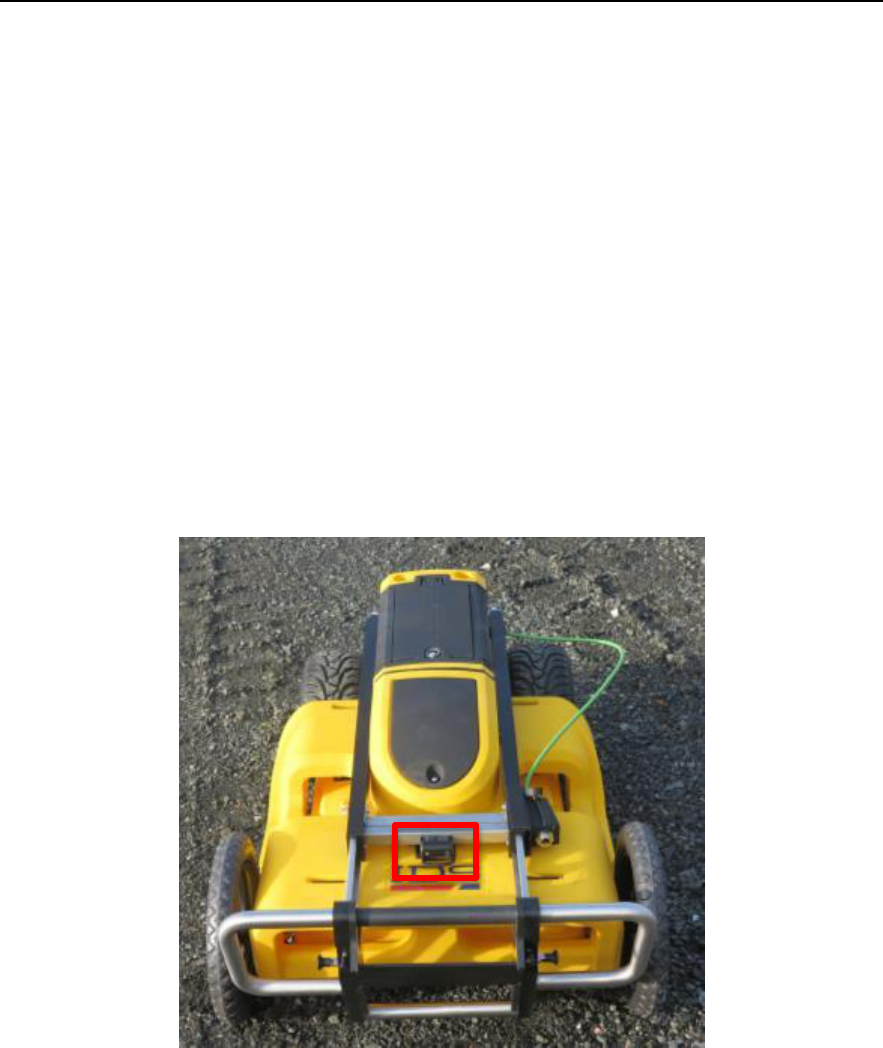
3.1.2 Control unit
The Control Unit, or DAD, is the central part of the system because it communicates with
the antenna, the laptop and the encoder, making all the systems work together.
The DAD is lodged in the antenna box and has a power button on top of it to turn it on/off
(see Fig. 3.1).
The characteristics of the Control Unit are:
Voltage: 12 V +/- 10%
Environment feature: IP 65
Absorbed power: 8 W
Operating temperature: -10/+40 °C
Fig. 3.1 – DAD power button
3.1.3 Encoders
The Opera Duo employs two encoders for acquisition distance measuring, each one is
positioned inside one of the wheels.
This feature ensures that the distance is correctly registered even in rough terrain when, at
times, only one wheel is touching the ground.
IDS Ingegneria Dei Sistemi S.p.A.
N doc:MN/2014/024 - Rev. 1.0
OPERA DUO v. 1.0 – User Manual
19 / 34
All information contained in this document is property of IDS. All rights reserved
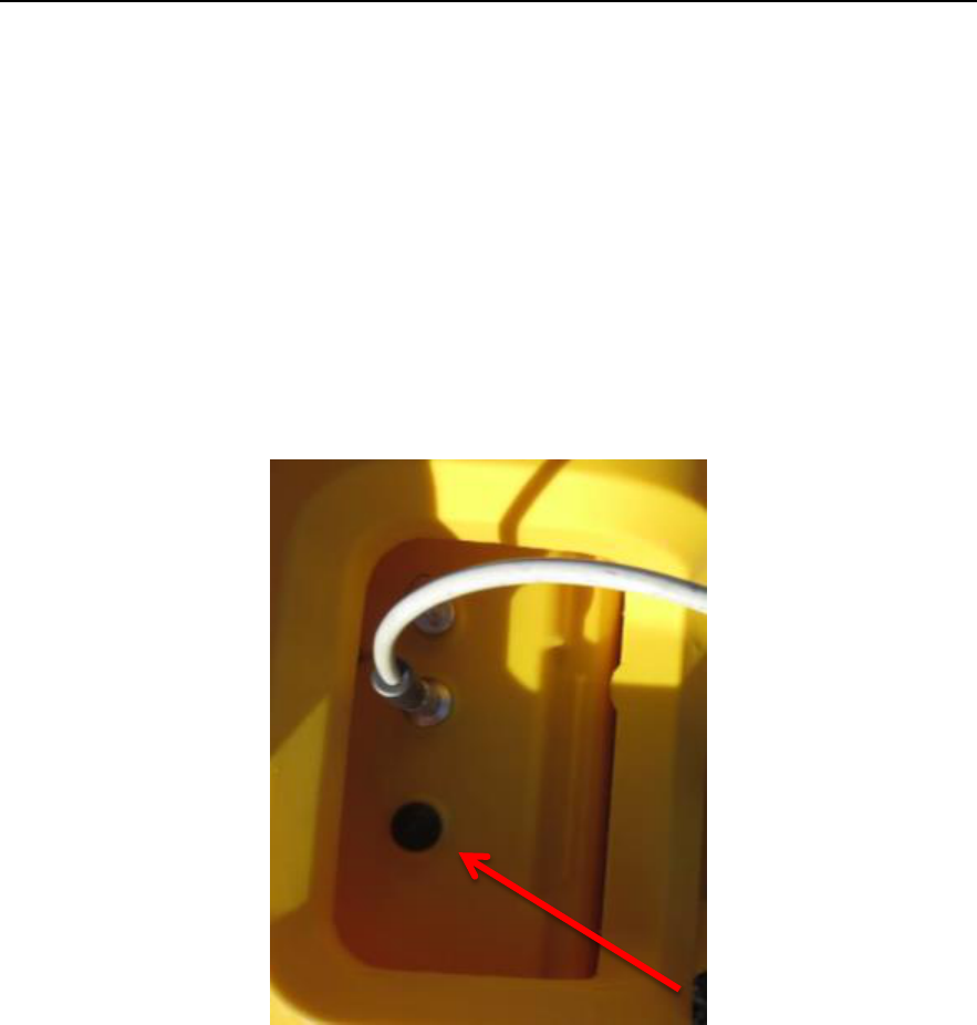
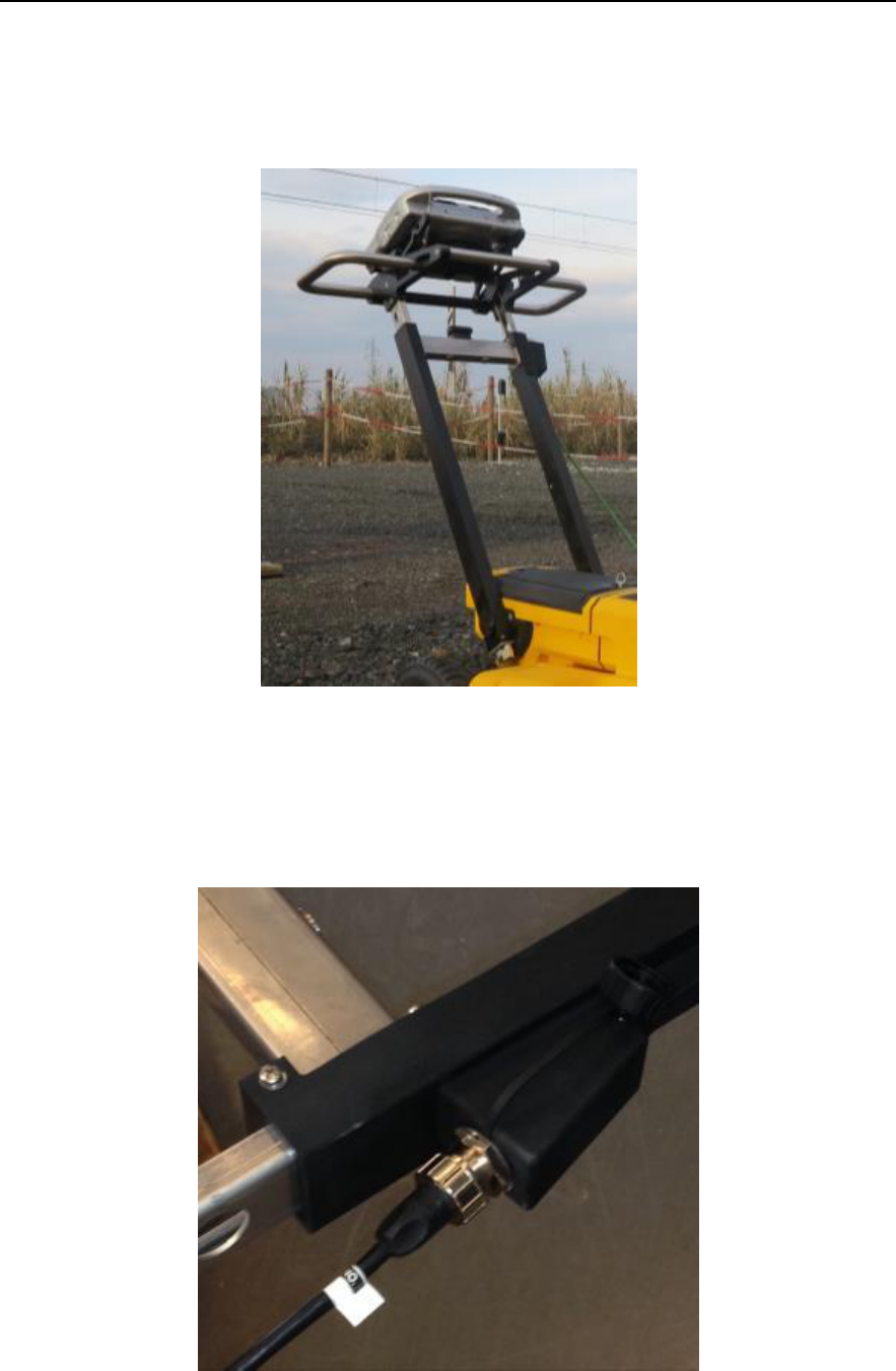
3.1.4 Handle
The Opera Duo handle is an ergonomic and adjustable handle bar (Fig. 3.2) that can be
adjusted both in height and inclination (see paragraph 4.1).
Fig. 3.2 – Opera Duo handle
The Laptop support is mounted on the Handle bar (see paragraph 3.1.6).
The Handle bar also contains the Ethernet cable that goes to the laptop (Fig. 3.3).
Fig. 3.3 – Ethernet cable plug on the handle
IDS Ingegneria Dei Sistemi S.p.A.
N doc:MN/2014/024 - Rev. 1.0
OPERA DUO v. 1.0 – User Manual
20 / 34
All information contained in this document is property of IDS. All rights reserved
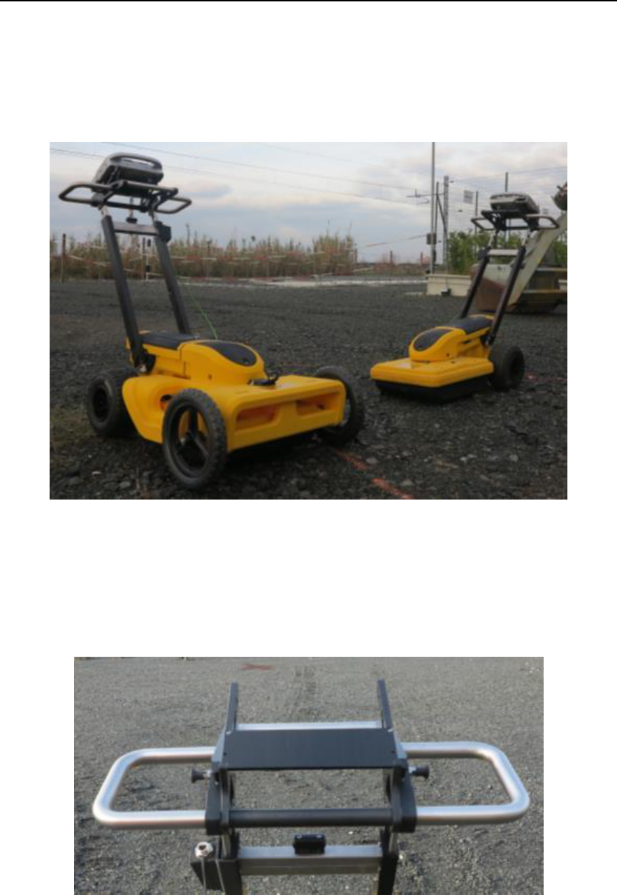
3.1.5 Wheels
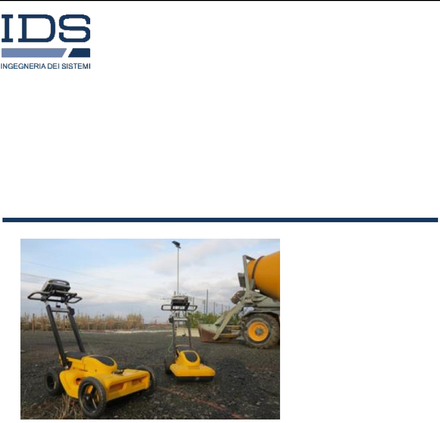
The Opera Duo comes in 2 and 4 wheeled versions (Fig. 3.4); the 2 wheeled version has tubeless
tires while the 4 wheeled version has 2 tubeless tires in the rear and 2 solid tires in the front.
The tubeless tires have to be inflated to a pressure of 2 bars.
Fig. 3.4 – Two and four wheeled versions of the Opera Duo
3.1.6 Laptop support
The inclination of the Laptop support can be adjusted to achieve the best viewing angle
for the user (Fig. 3.5).
Fig. 3.5 – Laptop support
IDS Ingegneria Dei Sistemi S.p.A.
N doc:MN/2014/024 - Rev. 1.0
OPERA DUO v. 1.0 – User Manual
21 / 34
All information contained in this document is property of IDS. All rights reserved
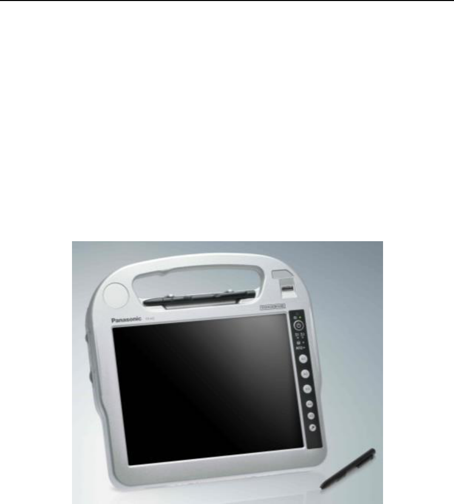
3.2 Laptop
The system can be provided with a laptop Panasonic CF-H2 (see Fig. 3.6), with the
software already installed; however the user can operate Opera Duo with any laptop
respecting the following recommended requirements:
Processor: i5 1.7 GHz
RAM: 2 GB Screen resolution: 1024 X 768
Operative system: Windows 7 or Windows 8
Hard disk: 40 Gb shock-proof
Serial port RS 232 (only used with the GPS)
USB port
Ethernet port
Fig. 3.6 – Panasonic CF-H2
IDS Ingegneria Dei Sistemi S.p.A.
N doc:MN/2014/024 - Rev. 1.0
OPERA DUO v. 1.0 – User Manual
22 / 34
All information contained in this document is property of IDS. All rights reserved
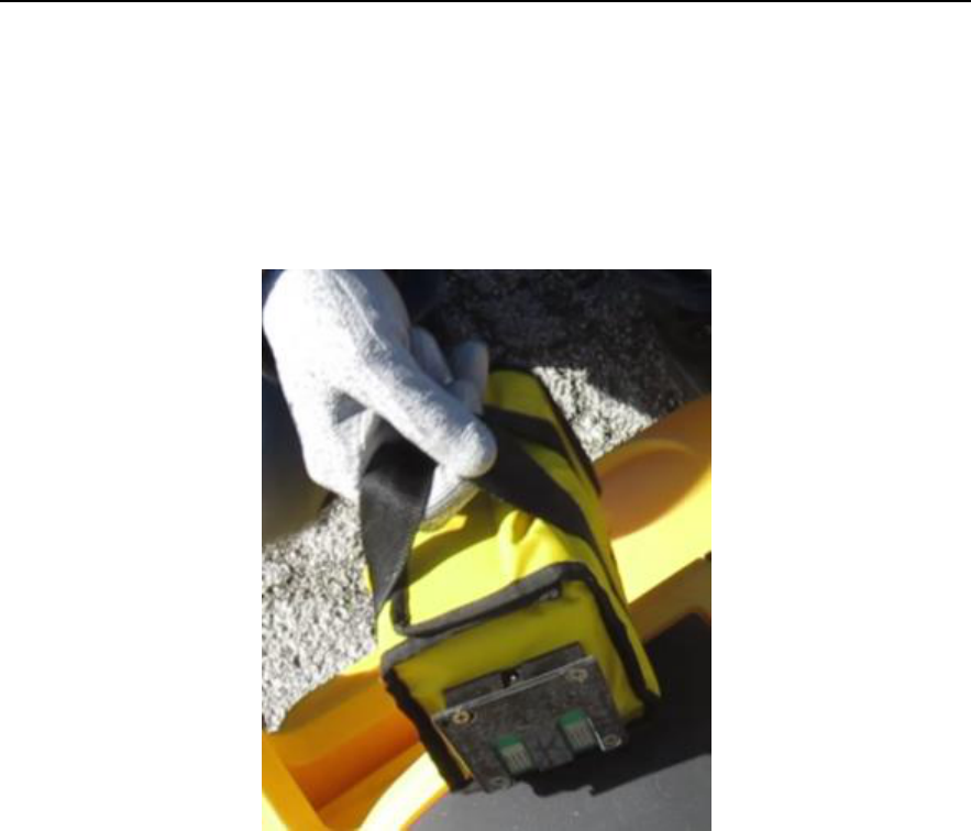
3.3 Battery
The battery used by an Opera Duo system provides power to the Control Unit and, from
there, to the Antenna, the Encoder and, if present, the Spray support; the battery does not
provide power to the laptop or the GPS, if present.
The Opera Duo battery is a 12 V / 12 AH rechargeable lead battery (see Fig. 3.7).
Fig. 3.7 – Opera Duo battery
IDS Ingegneria Dei Sistemi S.p.A.
N doc:MN/2014/024 - Rev. 1.0
OPERA DUO v. 1.0 – User Manual
23 / 34
All information contained in this document is property of IDS. All rights reserved
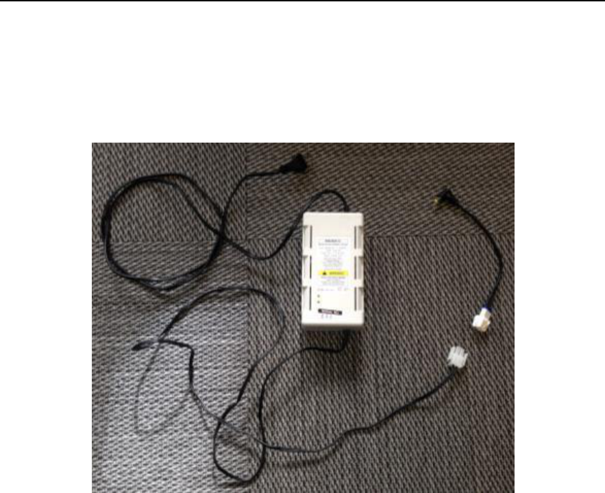
3.4 Battery charger
The battery charger is composed of two parts: a small cable to connect the battery to the
charger and the battery charger itself, to be connected to the electricity mains at AC
110/220 (see Fig. 3.8).
Fig. 3.8 – Battery charger
The battery can be charged whilst connected to the system or after having been removed.
Note that, in either case, the radar cannot be turned on during the battery charging.
IDS Ingegneria Dei Sistemi S.p.A.
N doc:MN/2014/024 - Rev. 1.0
OPERA DUO v. 1.0 – User Manual
24 / 34
All information contained in this document is property of IDS. All rights reserved
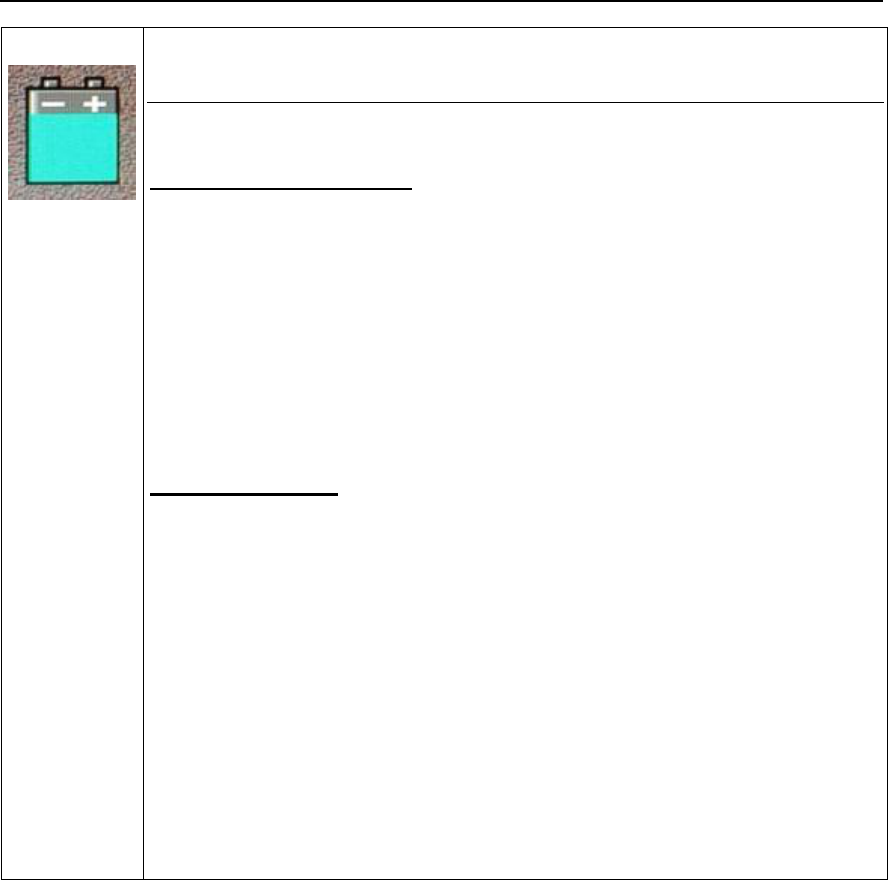
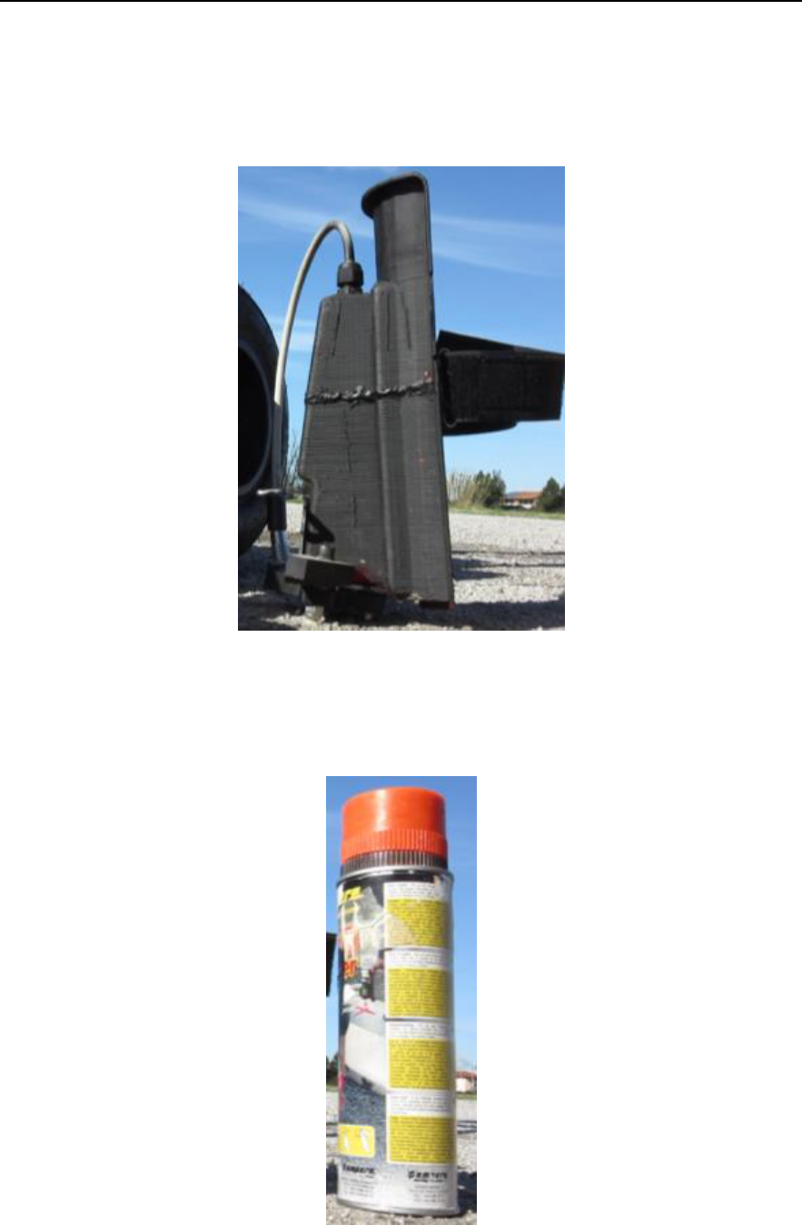
3.5 Spray support
The Spray support can be easily attached to the radar main body and contains a cable to be
connected to a socket in the upper part of the antenna lodging (see Fig. 3.9).
Fig. 3.9 – Spray support
The support must be used with a vertical spray spot marker (see Fig. 3.10).
Fig. 3.10 – Example of vertical spray spot marker
IDS Ingegneria Dei Sistemi S.p.A.
N doc:MN/2014/024 - Rev. 1.0
OPERA DUO v. 1.0 – User Manual
25 / 34
All information contained in this document is property of IDS. All rights reserved
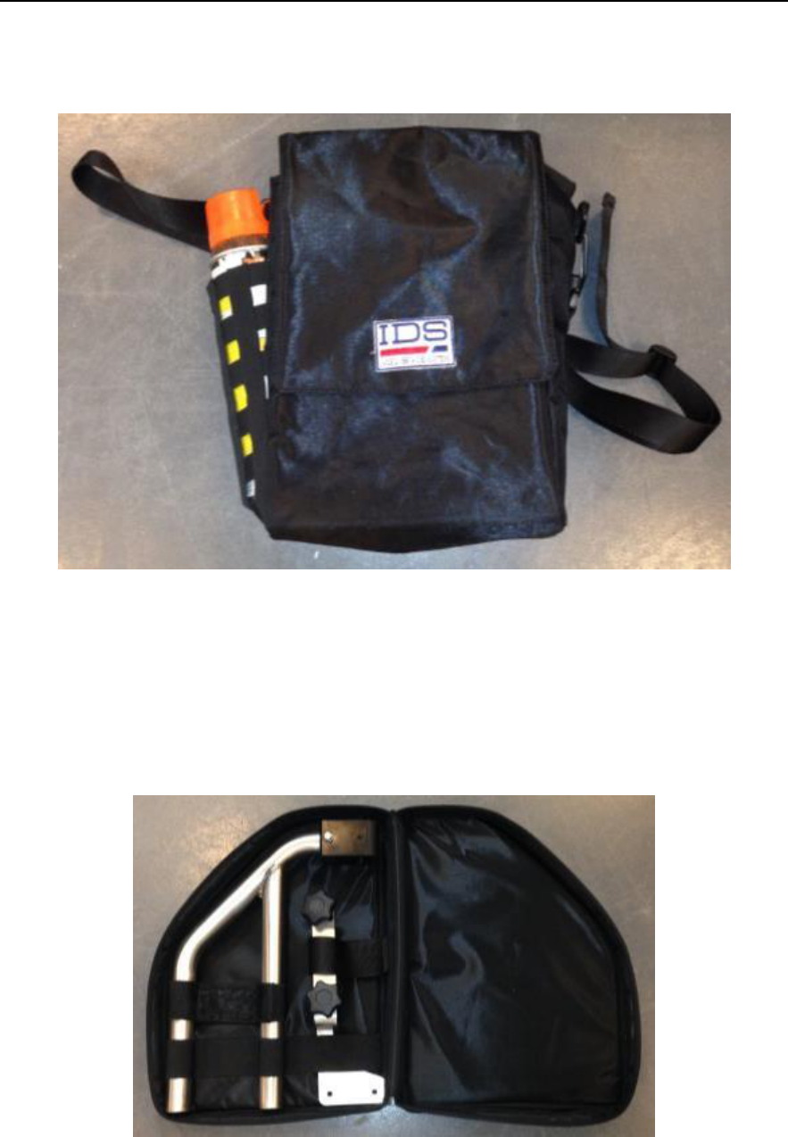
The Spray support is provided with a storage bag that can also contain an additional spray can
(see Fig. 3.11).
Fig. 3.11 – Spray support storage bag
3.6 GPS support
The GPS support is composed of two parts that have to be mounted on the radar main
body and holds the GPS pole (see Fig. 3.12).
Fig. 3.12 – GPS Support in the storage bag
IDS Ingegneria Dei Sistemi S.p.A.
N doc:MN/2014/024 - Rev. 1.0
OPERA DUO v. 1.0 – User Manual
26 / 34
All information contained in this document is property of IDS. All rights reserved
4. ASSEMBLY PROCEDURE
The procedure to assemble the Opera Duo is very simple and can be performed by one
person.
To assemble the system follow these steps:
1. Unfold the radar main body (paragraph 4.1);
2. Connect the laptop (paragraph 4.2);
3. Insert the battery (paragraph 4.3);
4. Mount the Spray support (optional, paragraph 4.4);
5. Mount the GPS support (optional, paragraph 4.5).
4.1 Unfold the radar main body
To unfold the Opera Duo main body place it to on the ground, press the central handle
button and raise the rudder to the desired angle (Fig. 4.1).
Fig. 4.1 – Unfold the Opera Duo
IDS Ingegneria Dei Sistemi S.p.A.
N doc:MN/2014/024 - Rev. 1.0
OPERA DUO v. 1.0 – User Manual
27 / 34
All information contained in this document is property of IDS. All rights reserved
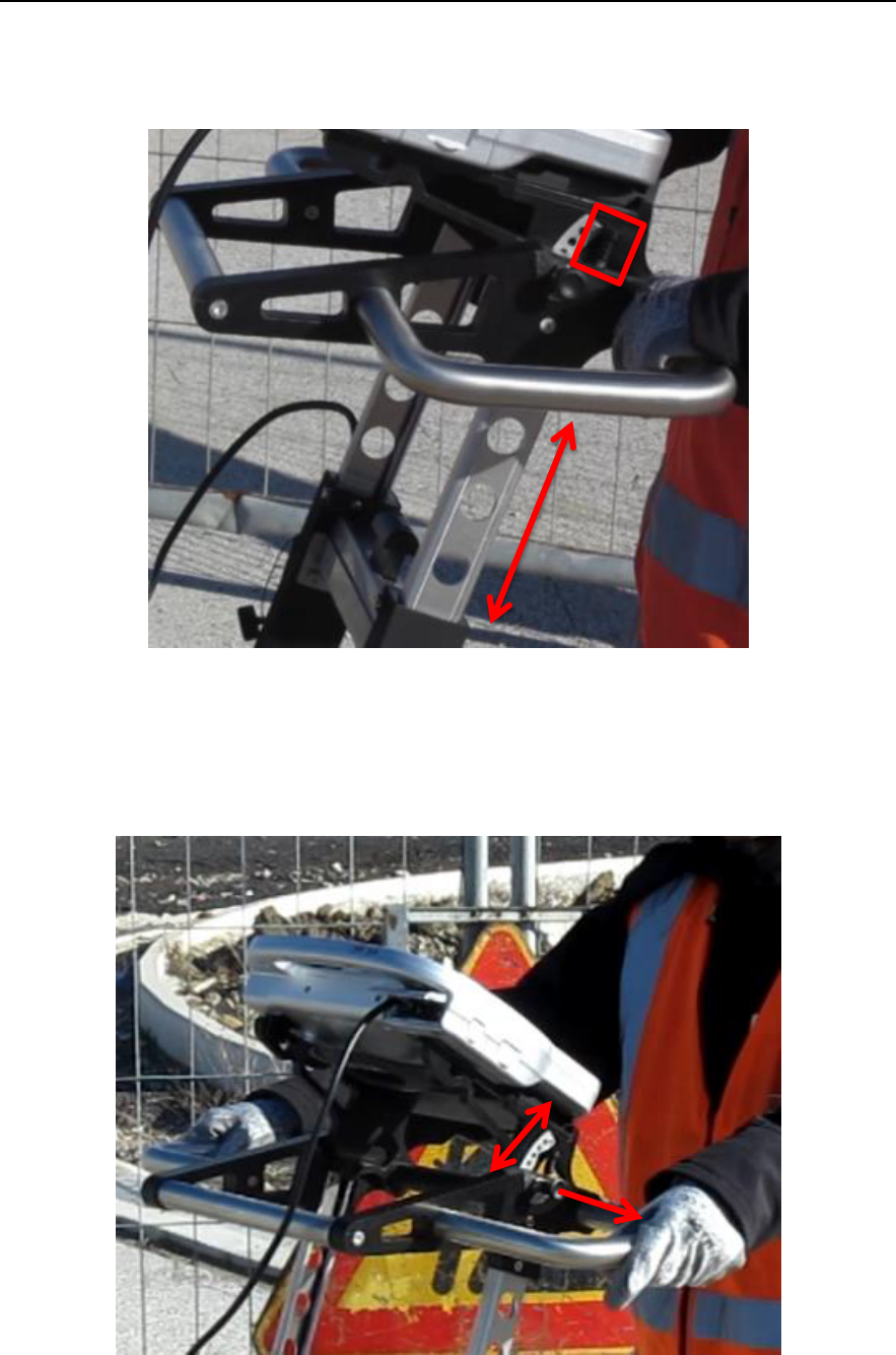
The user can also adjust the height of the handle bars and laptop support using the two
vertical buttons in the upper part of the rudder (Fig. 4.2).
Fig. 4.2 – Handle bar and laptop support height regulation buttons
The inclination of the laptop support can be changed opening the two horizontal locks on
its sides (Fig. 4.3).
Fig. 4.3 – Laptop support inclination regulation
IDS Ingegneria Dei Sistemi S.p.A.
N doc:MN/2014/024 - Rev. 1.0
OPERA DUO v. 1.0 – User Manual
28 / 34
All information contained in this document is property of IDS. All rights reserved
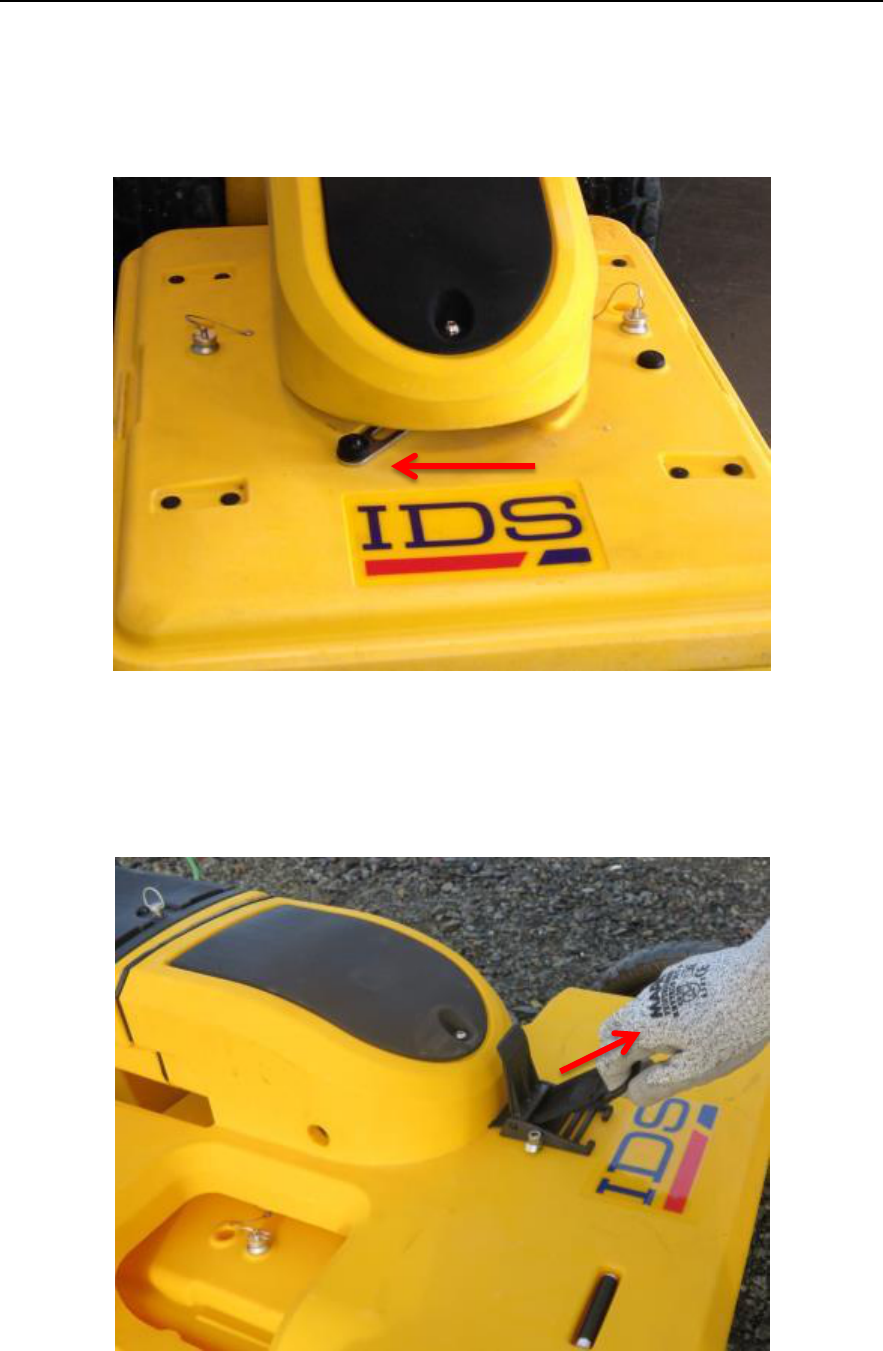
In the 2 wheeled version, the antenna movement has to be unlocked by putting the front
lever in the left position (Fig. 4.4); if the lever is in the central position the antenna will
have limited mobility, useful for rough terrain; while the right position is used for the
transportation of the folded system.
Fig. 4.4 – Antenna locking lever for two wheeled version
In the 4 wheeled version, the antenna can be slightly raised from the ground by pulling the
strap shown in Fig. 4.5.
Fig. 4.5 – Antenna height regulation
IDS Ingegneria Dei Sistemi S.p.A.
N doc:MN/2014/024 - Rev. 1.0
OPERA DUO v. 1.0 – User Manual
29 / 34
All information contained in this document is property of IDS. All rights reserved
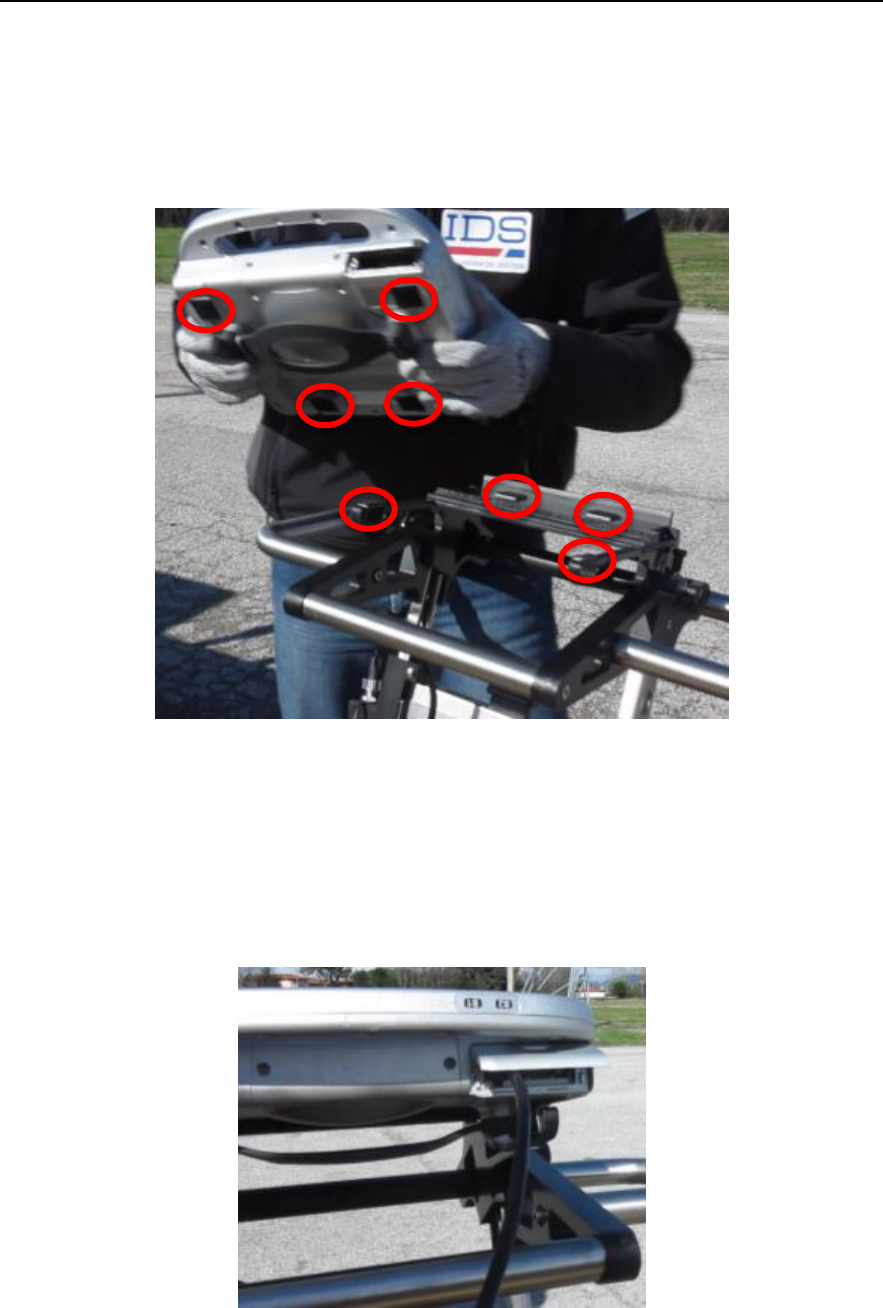
4.2 Connect the laptop
The laptop support on the radar main body is complete with Velcro strips; to attach the
laptop to the support press down until the Velcro strips on the support are securely
attached to the Velcro strips on the laptop (see Fig. 4.6).
Fig. 4.6 – Velcro strips on the Laptop and Laptop support
The CF-H2 laptop provided with the radar already has the Velcro strips attached; if
another laptop is used instead, the user should attach the Velcro strips (provided with the
radar) to this laptop.
Once the laptop is in place the user must connect the Ethernet cable (Fig. 4.7).
Fig. 4.7 – Ethernet connection
IDS Ingegneria Dei Sistemi S.p.A.
N doc:MN/2014/024 - Rev. 1.0
OPERA DUO v. 1.0 – User Manual
30 / 34
All information contained in this document is property of IDS. All rights reserved
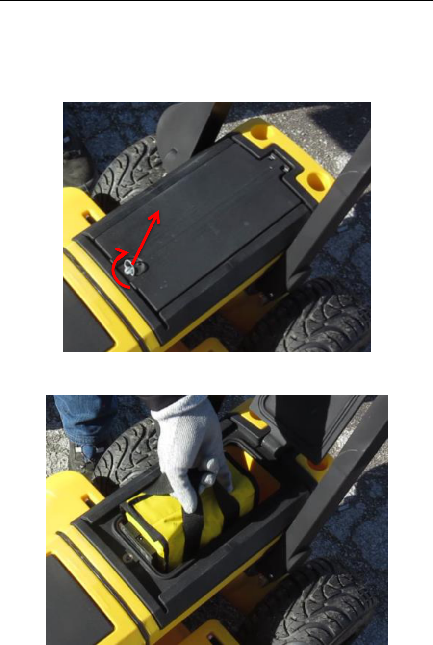
4.3 Insert the battery
To connect the battery open the dedicated compartment by turning and pulling the
metallic ring (Fig. 4.8), slide the battery inside with the plastic connector facing the front
of the radar (Fig. 4.9) and then close the compartment.
Fig. 4.8 – Battery compartment
Fig. 4.9 – Battery connection
IDS Ingegneria Dei Sistemi S.p.A.
N doc:MN/2014/024 - Rev. 1.0
OPERA DUO v. 1.0 – User Manual
31 / 34
All information contained in this document is property of IDS. All rights reserved
4.4 Mount the Spray support
The Spray support is an optional component to hold and command the spray to mark
targets on the ground.
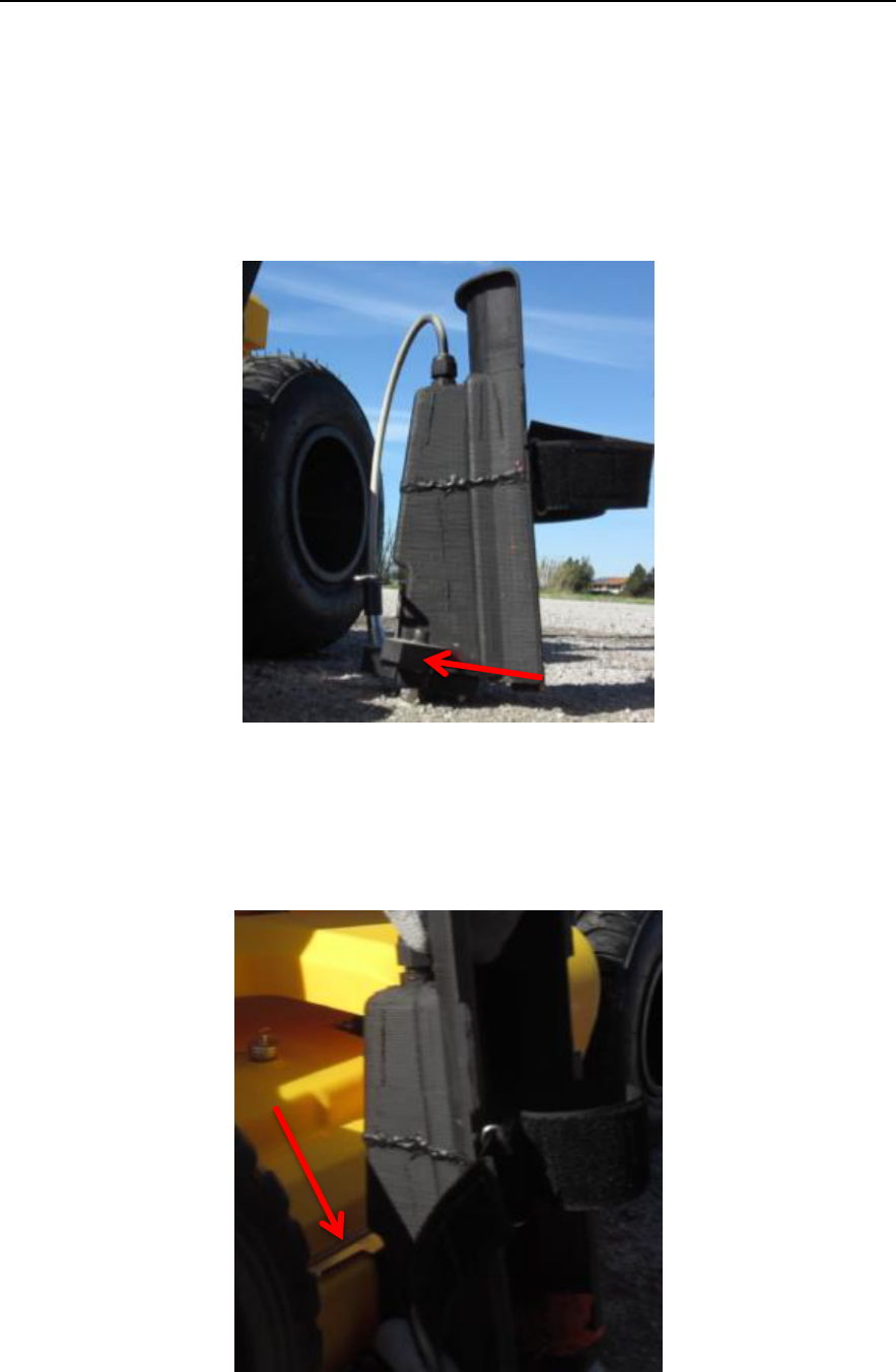
It can be mounted on either side of the antenna, following these steps:
1. Open the locks in the lower part of the spray support (Fig. 4.10);
Fig. 4.10 – Spray support locks
2. Fix the spray support to the radar main body, inserting first the upper part and
then the lower (Fig. 4.11);
Fig. 4.11 – Spray support fixing
IDS Ingegneria Dei Sistemi S.p.A.
N doc:MN/2014/024 - Rev. 1.0
OPERA DUO v. 1.0 – User Manual
32 / 34
All information contained in this document is property of IDS. All rights reserved
3. Close the locking system in the lower part of the spray support;
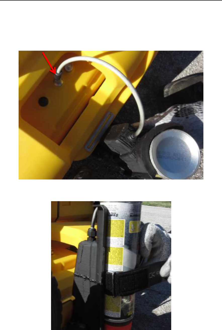
4. Connect the Spray cable to the dedicated connector (Fig. 4.12);
5. Insert the spray can into the support with the dispenser facing downward (Error!
eference source not found.).
Fig. 4.12 – Spray support cable connection
Fig. 4.13 – Spray can insertion
IDS Ingegneria Dei Sistemi S.p.A.
N doc:MN/2014/024 - Rev. 1.0
OPERA DUO v. 1.0 – User Manual
33 / 34
All information contained in this document is property of IDS. All rights reserved
4.5 Mount the GPS support
The GPS support is composed of two metallic parts whose purpose is to hold the GPS
pole. This pole is not provided with the radar.
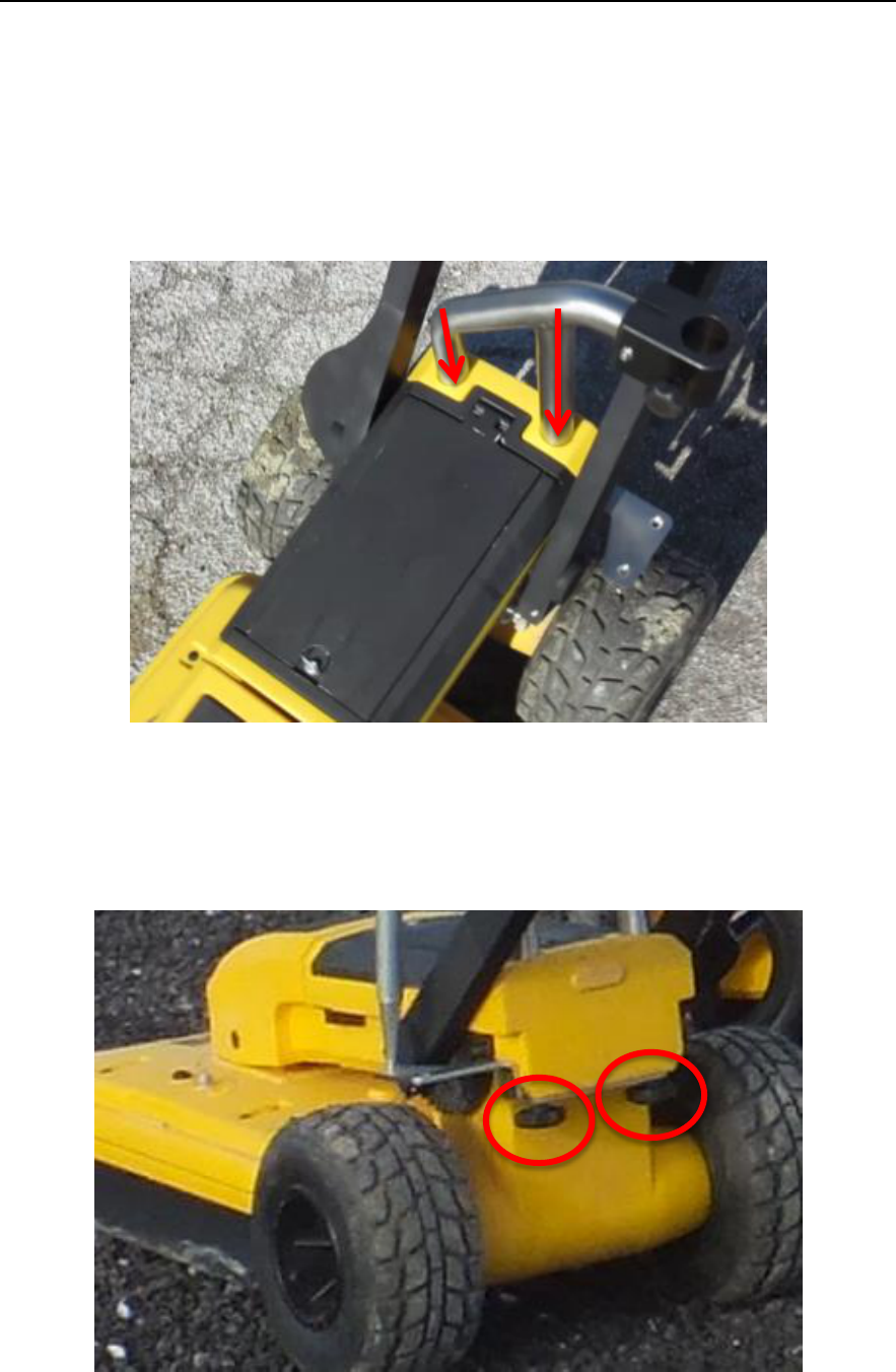
To mount the GPS support follow these steps:
1. Insert the upper part of the support into the two dedicated holes (Fig. 4.14);
Fig. 4.14 – GPS support upper part insertion
2. Screw the lower part to the Opera Duo main body using the two knobs, in this
way the two parts will be fixed together (Fig. 4.15).
Fig. 4.15 – GPS support lower part fixing

IDS Ingegneria Dei Sistemi S.p.A.
N doc:MN/2014/024 - Rev. 1.0
OPERA DUO v. 1.0 – User Manual
34 / 34
All information contained in this document is property of IDS. All rights reserved
4.6 Encoder calibration
The first time the system is used the metric wheels have to be calibrated; this operation
can also be repeated every time a difference between real and measured distance is noted.
First the user should inflate the tires to a pressure of 2 bars, then proceed with the wheel
calibration using the proper software tool (see paragraph Error! Reference source not
found.).