IDSC NEXIQ Technologies EDL3 Wireless Vehicle Communication Interface User Manual John Deere EDL3 Installation and Setup Manual
IDSC Holdings LLC dba NEXIQ Technologies Wireless Vehicle Communication Interface John Deere EDL3 Installation and Setup Manual
Exhibit D Users Manual per 2 1033 b3
John Deere
Electronic Data Link v3
Installation
and Setup Manual

John Deere Electronic Data Link v3 (EDL3) Installation and Setup Manual. The John Deere EDL3 was designed and
manufactured by IDSC Holdings LLC for Cummins Inc.
IDSC Holdings LLC retains all ownership rights to the EDL3 design and its documentation. The EDL3 source code is a
confidential trade secret of IDSC Holdings LLC. You may not decipher or de-compile the EDL3, develop source code for the
EDL3, or knowingly allow others to do so. The EDL3 and its documentation may not be sublicensed or transferred without
the prior written consent of IDSC Holdings LLC.
This manual, as well as the software it describes, is furnished under license and may only be used or copied in accordance
with the terms of such license. The content of this manual is furnished for informational use only, is subject to change without
notice, and should not be construed as a commitment by IDSC Holdings LLC. IDSC Holdings LLC assumes no responsibility
or liability for any errors or inaccuracies that may appear in this book.
Except as permitted by such license, no part of this publication may be reproduced, or transmitted, in any form or by any
means, electronic, mechanical, or otherwise, without the prior written permission of IDSC Holdings LLC.
The Bluetooth word mark and logos are registered trademarks owned by Bluetooth SIG. Other trademarks and trade
names are those of their respective owners.
©2016 IDSC Holdings LLC. All rights reserved. All other marks are trademarks or registered trademarks of the
respective holders. Pictures for illustration purposes only. Specifications are subject to change without notice.
The transmitter modules contained in this product comply with regulatory standards EN 300 328 and EN 301 489-1/
-17. Human exposure of these modules is below the SAR limits specified in EU recommendation 1995/519/EC.
This device complies with Part 15 of the FCC Rules. Operation is subject to the following two conditions: (1) this
device may not cause harmful interference, and (2) this device must accept any interference received, including
interference that may cause undesired operation. A distance of 20cm minimum should be maintained between the
product and all persons during operation. This device contains FCC-IDs : 2AJFJ-EDL3, QOQWT41.
Part No. 965061 Revised 09/15/2016
This device complies with Industry Canada licence-exempt RSS standard(s). Operation is subject to the following two
conditions: (1) this device may not cause interference, and (2) this device must accept any interference, including
interference that may cause undesired operation of the device.
Le présent appareil est conforme aux CNR d'Industrie Canada applicables aux appareils radio exempts de licence.
L'exploitation est autorisée aux deux conditions suivantes : (1) l'appareil ne doit pas produire de brouillage, et (2)
l'utilisateur de l'appareil doit accepter tout brouillage radioélectrique subi, même si le brouillage est susceptible d'en
compromettre le fonctionnement.

John Deere Electronic Data Link v3 Installation and Setup Manual 1
1
Using
this Manual
Manual Overview, page 2
Conventions, page 3
This chapter provides an overview of this manual’s organization and the conventions
used throughout.
NOTE:
iScreen shots used throughout this manual are for illustrative purposes only. All data
shown is fictitious in nature.

2 John Deere Electronic Data Link v3 Installation and Setup Manual
Chapter 1 • Using this Manual
Manual Overview
This manual provides basic and detailed information to support you during instal-
lation and setup of the Electronic Data Link v3 (EDL3).
This manual is composed of the following sections:
•Table of Contents—helps you to find the information you are looking for
quickly and easily.
•Chapter 1: Using this Manual—provides an overview of this user’s
manual.
• Chapter 2: Introducing the Electronic Data Link v3—provides details re-
garding the communication modes available to you to interface with your
PC. It also introduces the features of the EDL3 (i.e., the LEDs, the Reset
Button, the USB port, and the Vehicle port).
•Chapter 3: Installing the Drivers and Setting Up the Device—provides in-
structions for installing EDL3 drivers and utilities, connecting the EDL3
to a vehicle, connecting to a wireless network, and testing the connec-
tion. It also provides information on using the EDL3 Explorer utility.
Each chapter begins with an “at-a-glance” list of the chapter contents, along with
corresponding page numbers.

- Conventions
John Deere Electronic Data Link v3 Installation and Setup Manual 3
Conventions
This section provides descriptions of the conventions used throughout this guide.
Special Messages
Note
NOTE provides an explanation, comment, or tip related to the subject matter that
is being discussed.
Example:
NOTE:
iRefer to the page number provided for each described component for fur-
ther details.
Important
IMPORTANT indicates a situation which, if not avoided, may result in damage to
the test equipment or vehicle.
Example:
IMPORTANT:
äKeep all cables clear of moving or hot engine parts.
Caution
CAUTION indicates a potentially hazardous situation which, if not avoided, may
result in moderate or minor injury to the operator or to bystanders.
Example:
CAUTION:
äDo not use the unit to perform tests on household or industrial sources.

4 John Deere Electronic Data Link v3 Installation and Setup Manual
Chapter 1 • Using this Manual
Warning
WARNING indicates a potentially hazardous situation which, if not avoided, could
result in death or serious injury to the operator or bystanders.
Example:
WARNING:
äAll RP1210 adapters must be disconnected before proceeding with
installation.
Troubleshooting
Information intended to help you to address or anticipate potential issues are pre-
sented in the following manner:
Check to make certain that the Power LED on the EDL3 is
illuminated.
Specialized Text
The following specially formatted text is used to help you to differentiate certain
elements discussed within this manual:
•Emphasis: Used to draw your attention to particularly important
information.
•FEATURE: Used to highlight the name of a specific feature.
Example: “Click on the Finish button to continue.”
•Field/Line: Used to highlight the name of a field or a line of text from a
display.
Example: “Place a check mark in the Always trust software from IDSC
Holdings LLC check box.”
• Menu Items: Used to highlight a series of menu selections.
Example: “From the Start menu, select Programs Deere
EDL3EDL3 Explorer”
• Screen titles: Used to highlight the title of a screen displayed.
Example: “The Installation Complete screen is displayed.”

John Deere Electronic Data Link v3 Installation and Setup Manual 5
2
Introducing the John
Deere Electronic Data
Link v3
Component Checklist, page 6
Product Specifications, page 7
System Requirements, page 8
Device Features, page 9
Communication Options: Wired vs Wireless, page 13
Wired USB Connection, page 13
Wireless Bluetooth Connection, page 14
Wireless Wi-Fi Connection, page 15
Mini Access Point Mode (Peer-to-Peer), page 16
Infrastructure Mode (Connecting to your Company’s Network), page 17
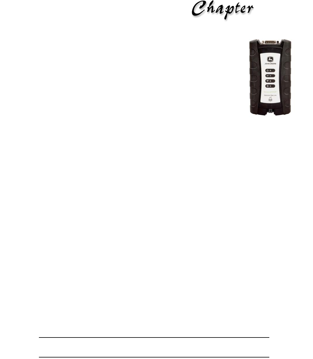
The Electronic Data Link v3 (EDL3) is a hardware device that enables service bay
personal computers (i.e., PCs and/or laptops) to retrieve vehicle information using either
wireless Bluetooth® technology, a more traditional cable connection, or Wi-Fi. Once
configured, the EDL3 interfaces with your PC, enabling you to use specific PC
applications to perform vehicle diagnostics.
This chapter introduces the EDL3 and provides details regarding the communication
modes available to you to interface with your PC. It also introduces the features of the
EDL3 (i.e., the LEDs, the Reset Button, the USB port, and the Vehicle port).

6 John Deere Electronic Data Link v3 Installation and Setup Manual
Chapter 2 • Introducing the John Deere Electronic Data Link v3
Component Checklist
The following components are included with your EDL3. Be sure you have all of
the following items before using the device:
EDL3
Automotive A to Mini-B USB Cable (see Figure 2.2)
W1 9-pin Deutsch Adapter
Carrying Case
NOTE:
iEDL3 drivers are included with your John Deere Service ADVISOR™
diagnostic software, or may be supplied separately via download, disk, or
USB flash drive.
- Product Specifications
John Deere Electronic Data Link v3 Installation and Setup Manual 7
Product Specifications
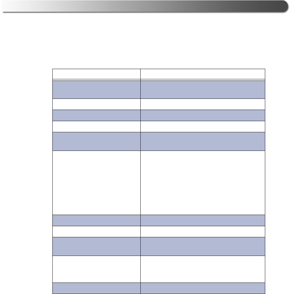
The EDL3 Data Link Adapter is configured with the following specifications:
Feature Data
Physical Dimensions 6.75" x 3.75" x 1.06"
(171 mm x 95 mm x 27 mm)
Weight 8 oz. (0.22 kg)
Power Requirements 6 - 32 VDC @ 350 mA maximum
Operating Temperature 0 to +70 °C
API Driver TMC RP1210A, RP1210B, and RP1210C
compliant
Vehicle Protocols Supported • J1708/J1587
• J1939 (250K, 500K, or 1 MB)
• CAN (125K, 250K, 500K, 1 MB)
(4 CAN channels with Auto Baud)
• ISO 9141
• ISO 14230 (KWP2000)
• ISO 15765
• CCD
USB Communication USB Device, version 1.1
USB Connector Latching USB Mini-B
Wired Communication Automotive A to Mini-B USB cable 13 ft.
(4 m) maximum
Wireless Communication • Bluetooth® Class 1 adapter (up to 100
m range)
• Dual band Wi-Fi (802.11 a/b/g/n)
Vehicle Connector High Density D-sub 26-pin Male (HD26M)

8 John Deere Electronic Data Link v3 Installation and Setup Manual
Chapter 2 • Introducing the John Deere Electronic Data Link v3
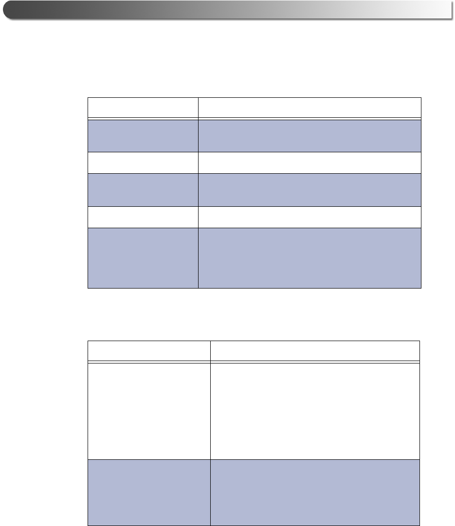
System Requirements
Be aware of the following system requirements:
Component Requirement
IBM PC-compatible
computer
• 1GHz processor or more
• RAM: 256MB or more (512MB recommended)
• USB port, version 1.1 or higher
•Wi-Fi card
Operating system • Windows® 7
• Windows® 8
• Windows® 10
Bluetooth® adapter
(sold separately)
• Bluetooth® Class 1 USB Adapter (up to 100m
range)
Note: PCs that have Integrated Bluetooth
typically use a Class 2 Bluetooth® module,
which has limited range (typically 10m).
Wi-Fi wireless
network
•Dual band Wi-Fi (802.11a, b, g, or n)
- Device Features
John Deere Electronic Data Link v3 Installation and Setup Manual 9
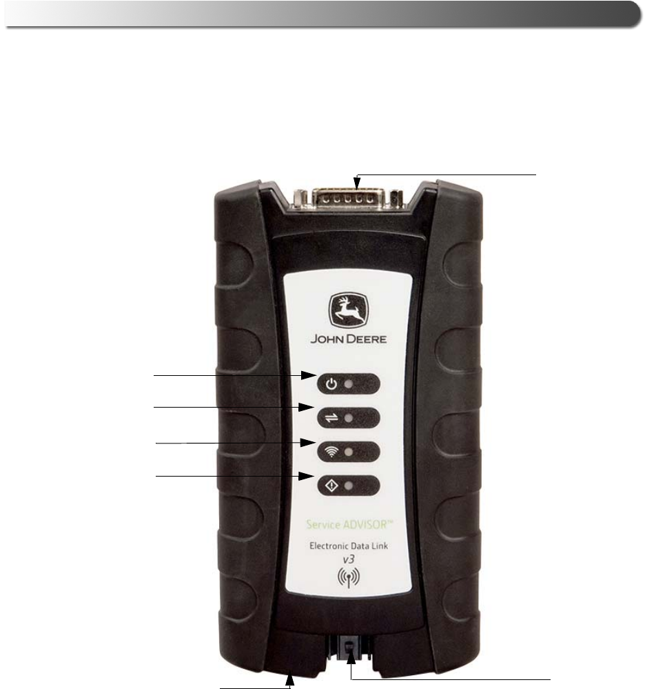
Device Features
The following illustration details the features of the EDL3 device.
A
F
Reset Button
B
C
D
E
Figure 2.1 John Deere Electronic Data Link v3
Legend
A—Vehicle Port D—Wireless Comm LED
B—Power LED E—Fault LED
C—Vehicle Data LED F—USB Port
10 John Deere Electronic Data Link v3 Installation and Setup Manual
Chapter 2 • Introducing the John Deere Electronic Data Link v3
The following features behave the same whether the device is in Bluetooth®
or Wi
Feature What It Does
Vehicle Port Connects the EDL3 to a vehicle/engine for power
and data.
Power LED Illuminates when the device receives power.
Vehicle Data LED Illuminates when the device is receiving data from
the vehicle.
Fault LED Illuminates when a problem is detected.
USB Port Connects the device to your PC (wired
connection).
Latching USB Mini-B Connector for connection to
PC host. Not used with iOS device.
-Fi mode:
The Wireless LED and the Reset Button, however, behave differently depend-
ing on which mode (i.e., Bluetooth or Wi-Fi) the device is in.
Feature What It Does
Wireless Comm LED:
Blue: Bluetooth Mode
If the device is Discoverable:
• Illuminates solid blue when connected.
• Blinks every second when not connected.
If the device is Non-Discoverable:
• Illuminates blue when connected.
• Off when not connected.
Wireless Comm LED:
White: Wi-Fi—Mini
Access Point Mode
Mini Access Point Mode:
• Illuminates solid white when a client PC
connects to the device.
• Off when no client PC is connected.

- Device Features
John Deere Electronic Data Link v3 Installation and Setup Manual 11
Wireless Comm LED:
Orange: Wi-Fi—Infra-
structure Mode
Infrastructure Mode:
• Stays off when not associated with a
network Access Point.
• Blinks every second when associated with
an access point, but no IP address
assigned.
• Illuminates solid orange when successfully
assigned an IP address.
Reset Button
Bluetooth Mode
The EDL3 factory default is Bluetooth mode in
a Non-Discoverable status. To confirm that the
device is in Bluetooth mode, press the Reset
button momentarily and the Wireless LED will
illuminate blue.
In Bluetooth mode, the Reset button is used to
change the status of the device. The two status
modes are:
•Non-Discoverable—When the EDL3 is
Non-Discoverable, it will only connect to a
host device with which it has previously
been paired.
•Discoverable—When the EDL3 is Discov-
erable, a host device can detect, pair, or
connect to it.
To change the mode from Non-Discoverable to
Discoverable, press and hold the Reset button
until the Wireless LED begins to flash blue
(about 3 seconds).
Once a connection is established, the LED
turns solid blue. After two minutes, discover-
ability will time out, and the device will go back
to Non-Discoverable status.
Feature What It Does

12 John Deere Electronic Data Link v3 Installation and Setup Manual
Chapter 2 • Introducing the John Deere Electronic Data Link v3
Reset Button
Wi-Fi Mode
When using Wi-Fi, the EDL3 can be configured
for either of the following modes:
• Mini-Access Point (Wi-Fi default)
• Infrastructure
Note: EDL3 cannot be used in Infrastructure
mode until it has been configured using the
Explorer utility (see Using the EDL3 Explorer in
Chapter 3 of this manual).
Once Infrastructure mode has been config-
ured, you can switch between Mini-Access
Point and Infrastructure modes by pressing
and holding the Reset button for three (3)
seconds. The LED will change color to indicate
the mode change.
Reset Button
(to switch modes)
The Reset button is also used to switch back
and forth between Bluetooth and Wi-Fi modes.
To switch modes, press and hold the Reset
button for about ten (10) seconds. All LEDs will
flash momentarily to indicate that the device
has been reconfigured and reset.
Once the device reboots, the color of the
Wireless LED will reflect the wireless mode:
•Blue = Bluetooth mode
•White = Wi-Fi, Mini Access Point mode
•Orange = Wi-Fi, Infrastructure mode
Feature What It Does
- Communication Options: Wired vs Wireless
John Deere Electronic Data Link v3 Installation and Setup Manual 13
Communication Options: Wired vs Wireless
Prior to using the EDL3, you need to decide how you want the unit to communicate
with your PC. There are three options:
• Wired, USB Connection (pg. 13)
• Wireless, Bluetooth® Connection (pg. 14)
• Wireless, Wi-Fi Connection (pg. 15)
Wired USB Connection
A wired USB connection provides the advantages of high data throughput, low
latency, and a high-reliability data connection.
IMPORTANT:
äECU reprogramming typically requires both high throughput and critical
timing, and should always use a USB-to-PC wired connection.
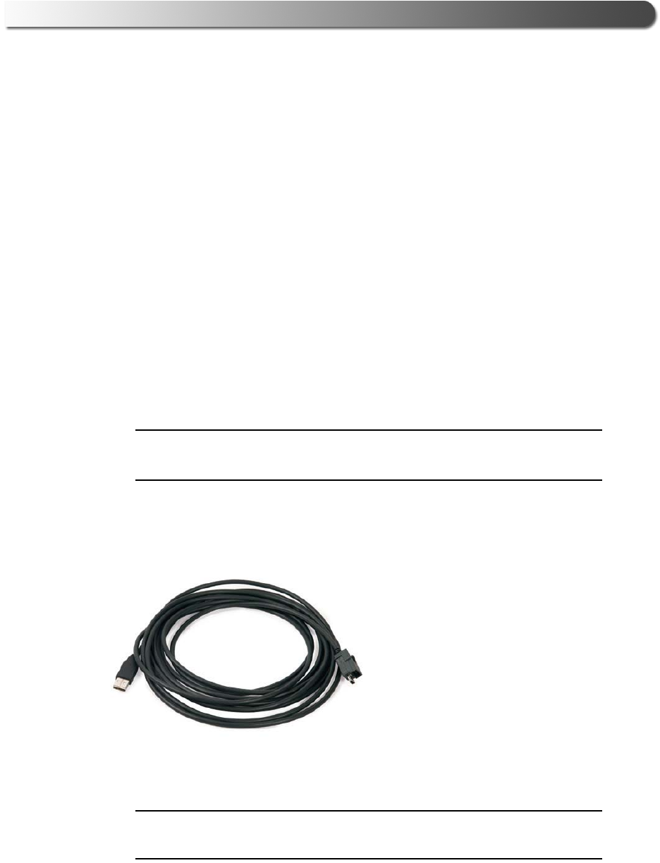
Wired communication between the EDL3 and your PC requires an automotive A
to Mini-B USB cable (shipped with the EDL3).
Figure 2.2 Automotive A to Mini-B USB Cable
NOTE:
iFor detailed instructions on making a wired connection, refer to Making a
Wired USB Connection in Chapter 3 of this manual.

14 John Deere Electronic Data Link v3 Installation and Setup Manual
Chapter 2 • Introducing the John Deere Electronic Data Link v3
Wireless Bluetooth Connection
The EDL3 can be configured to use Bluetooth® wireless technology to provide
communication between the EDL3 and your PC. Bluetooth® has limited bandwidth
and exhibits latency when compared to WI-FI or a wired USB connection. This
may result in dropped messages in situations requiring high bandwidth.
The EDL3 Data Link Adapter is equipped with a Class 1 Bluetooth® module with
a range of up to 100m when communicating with another Class 1 Bluetooth®
device. Most PCs that feature Integrated Bluetooth® are equipped with a Class 2
Bluetooth® module, which limits the useful range to around 10m.
NOTE:
iFor maximum wireless range, the use of an external, Class 1 USB Blue-
tooth® adapter (sold separately) is recommended.
If you decide to employ an external, Class 1 USB Bluetooth® adapter, you will
have to perform the following tasks:
• Disable the integrated Bluetooth® device
• Install the drivers supplied with the external adapter
• Configure the Bluetooth® environment.
For detailed instructions on configuring the EDL3 for Bluetooth®, see Making a
Bluetooth Wireless Connection, in Chapter 3 of this manual.

- Communication Options: Wired vs Wireless
John Deere Electronic Data Link v3 Installation and Setup Manual 15
Wireless Wi-Fi Connection
The EDL3 can also be configured to use Wi-Fi to provide wireless communication
between the EDL3 and your PC.
There are two network options:
• Mini Access Point Mode (pg. 16)
• Infrastructure Mode (pg. 17)
Wi-Fi performance can be affected by network congestion or radio frequency in-
terference if there are too many other wireless devices in the vicinity.These
conditions may result in dropped messages. For this reason, Wireless communi-
cation is not recommended for ECU reprogramming (i.e, reflashing).
16 John Deere Electronic Data Link v3 Installation and Setup Manual
Chapter 2 • Introducing the John Deere Electronic Data Link v3
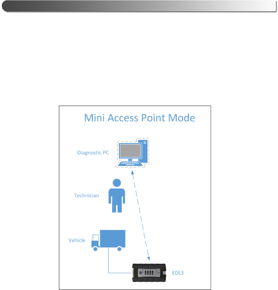
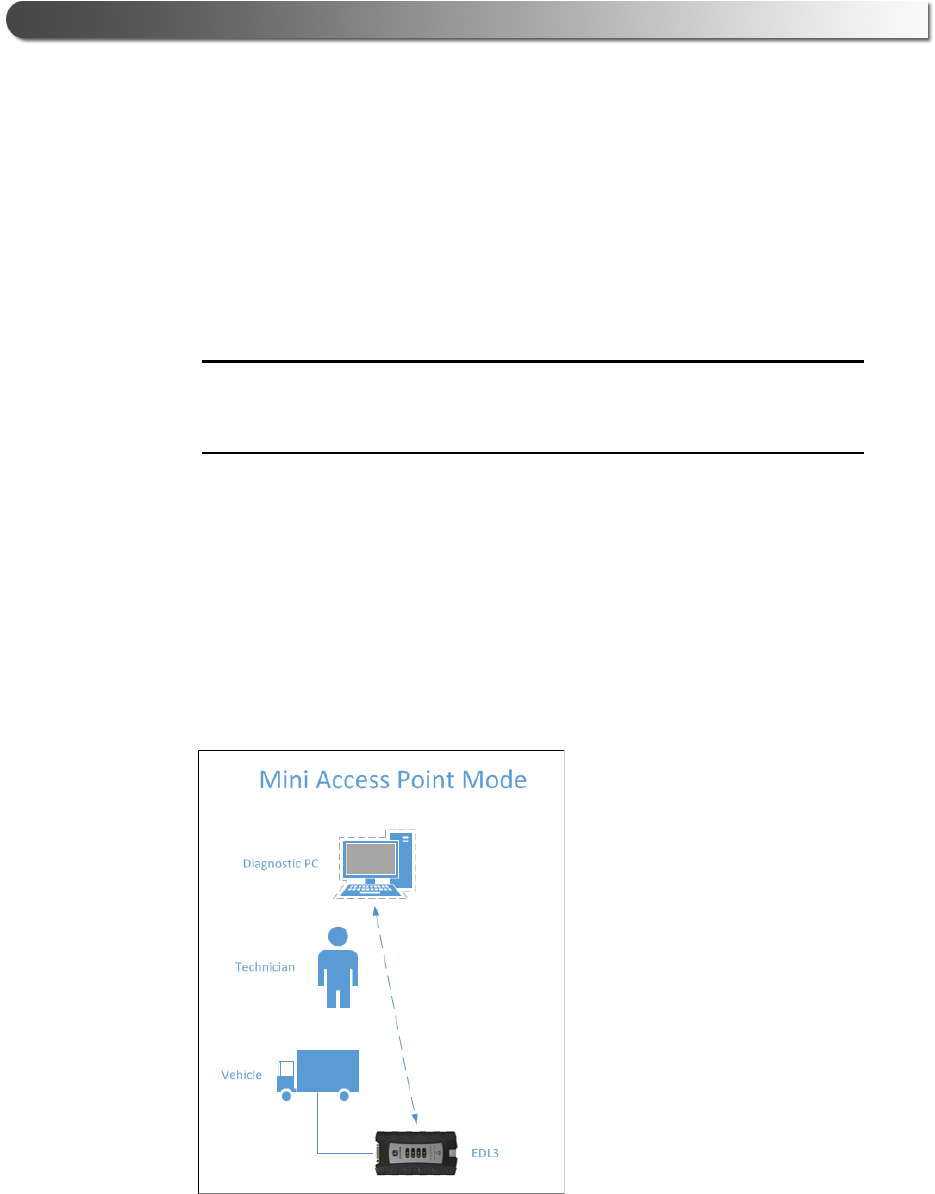
Mini Access Point Mode (Peer-to-Peer)
The easiest and quickest way to connect your EDL3 to your PC is Mini Access
Point mode. In Mini Access Point mode (also known as Access Point Emulation
mode), the PC communicates directly with the EDL3. The EDL3 emulates the
function of an access point, allowing the PC to connect directly to the EDL3, as if
it were an access point. When the PC is connected to the EDL3 in Mini Access
Point mode, neither device is connected to the company network.
Figure 2.3 Mini Access Mode
If you use your PC’s internal wireless network card to connect to your company’s
network and the Internet, you may want to obtain an additional wireless network
card for use with the EDL3. Otherwise when you connect the EDL3 to your PC
using Mini Access Point mode, you will not have access to the Internet until you
have finished your session and reconnected to your company’s network.
For instructions on connecting the EDL3 Data Link Adapter and your PC using
Mini Access Point Mode, see Connect Using Wi-Fi, in Chapter 3 of this manual.
- Communication Options: Wired vs Wireless
John Deere Electronic Data Link v3 Installation and Setup Manual 17
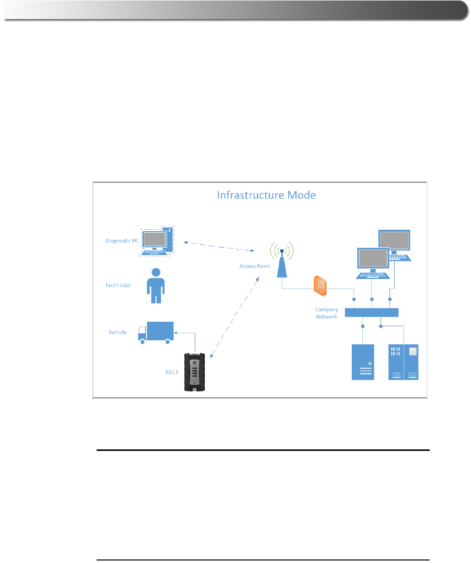
Infrastructure Mode (Connecting to your Company’s Network)
In Infrastructure mode, your PC communicates with your company’s computer
network through a Wireless Access Point (not included), which acts as a bridge
between the wireless network and the wired network. In this mode, the EDL3 is
configured to communicate with the same access point. All communication
between the PC and the EDL3 passes through the access point.
Figure 2.4 Infrastructure Mode
NOTE:
iThe settings for connecting to your company network may differ from one
installation to another. To ensure network security, your Information Tech-
nology (IT) administrator will need to oversee the installation and specify
the appropriate configuration parameters. Your IT administrator should be
able to properly configure the EDL3 for infrastructure mode, using the
EDL3 Explorer utility (see Switching Modes: Mini Access Point and Infra-
structure in Chapter 3 of this manual).

18 John Deere Electronic Data Link v3 Installation and Setup Manual
Chapter 2 • Introducing the John Deere Electronic Data Link v3
John Deere Electronic Data Link v3 Installation and Setup Manual 19
3
Installing the Drivers and
Setting Up the Device
Installation Process Outline, pg. 20
Step 1: Install the Drivers, pg. 21
Step 2: Connect the EDL3 to a Vehicle, pg. 29
Making a Wired USB Connection, pg. 30
Making a Wireless Bluetooth Connection, pg. 31
Connecting via a Class 1, External Bluetooth Adapter, pg. 31
Pair the Device, pg. 34
Making a Wireless Wi-Fi Connection, pg. 38
Mini Access Point Mode, pg. 38
Infrastructure Mode, pg. 42
Using the EDL3 Explorer Utility, pg. 43
This chapter provides instructions for installing the John Deere Electronic Data Link v3
(EDL3) drivers and utilities, connecting the EDL3 to a vehicle, connecting to a wireless
network, and testing the connection. It also provides information on using the EDL3
Explorer utility.
NOTE:
iScreen shots used throughout this manual are for illustrative purposed only. All data
shown is fictitious in nature.

20 John Deere Electronic Data Link v3 Installation and Setup Manual
Chapter 3 • Installing the Drivers and Setting Up the Device
Installation Process Outline
Step 1: Install the EDL3 drivers (pg. 21).
NOTE:
iIf you have previously installed John Deere Service ADVISOR™ software,
the EDL3 drivers are already installed on your laptop or PC. If this is the
case, skip this section and proceed to Step 2 on page 29 of this manual.
Step 2: Connect the EDL3 to the vehicle (pg. 29).
Connect to your PC using one of the following options:
•A wired, USB connection (pg. 30)
• A wireless, Bluetooth® connection (pg. 31)
• A wireless, Wi-Fi connection
There are two options:
—Mini Access Point Mode (pg. 38)
—Infrastructure Mode (pg. 42)

- Step 1: Install the Drivers
John Deere Electronic Data Link v3 Installation and Setup Manual 21
Step 1: Install the Drivers
NOTE:
iIf you have previously installed John Deere Service ADVISOR™ software,
the EDL3 drivers are already installed on your laptop or PC. If this is the
case, skip this section and proceed to Step 2 on page 29 of this manual.
If you are planning to use the EDL3 without Service ADVISOR™ software, or if
you need to update the EDL3 drivers that came with Service ADVISOR™, you will
need to install drivers supplied separately.
NOTE:
iEDL3 drivers may be supplied via download, disk, or USB flash drive.
Remember, you must have Administrator security rights and be logged in as
“Admin” to successfully complete the installation process outlined in this manual.
To install the drivers on your laptop or PC:
1Do one of the following:
—Either download the drivers to your hard disk (following instructions
supplied separately).
or
—Insert either the disk or the USB flash drive containing the drivers into your
PC or laptop.
2Locate and run the following file:
EDL3_setup.exe
22 John Deere Electronic Data Link v3 Installation and Setup Manual
Chapter 3 • Installing the Drivers and Setting Up the Device
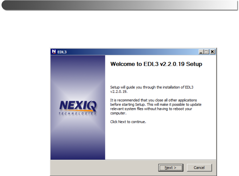
The Welcome to EDL3 Setup screen is displayed.
Figure 3.1 Welcome to EDL3 Setup Screen
3Carefully read the information displayed on the screen, and follow the
recommendations.
4Click Next.
- Step 1: Install the Drivers
John Deere Electronic Data Link v3 Installation and Setup Manual 23
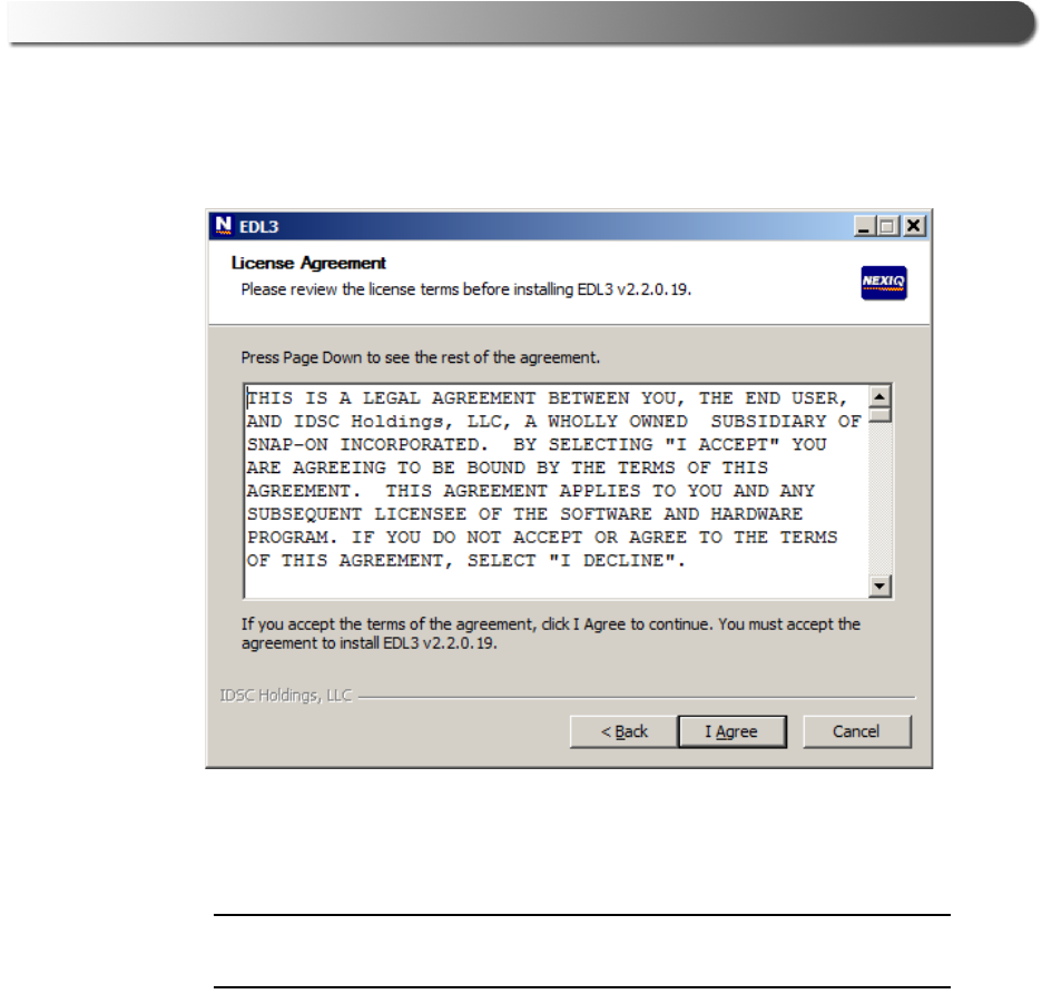
The License Agreement screen is displayed.
Figure 3.2 License Agreement Screen
5Read all the information on this screen, then click I Agree.
NOTE:
iIf you do not agree to the terms, click Cancel. A message is displayed
prompting you to confirm quitting EDL3 Setup. Click Yes to quit.
24 John Deere Electronic Data Link v3 Installation and Setup Manual
Chapter 3 • Installing the Drivers and Setting Up the Device
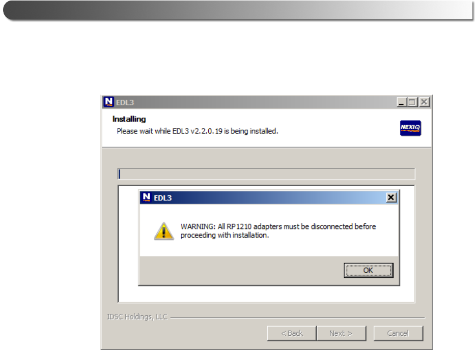
The following warning message is displayed.
Figure 3.3 Warning Message
6Carefully read the warning message, and disconnect all RP1210 adapters to
which your laptop or PC might be connected prior to proceeding with the
installation.
7Once you have complied with the requirements of the warning message, click
OK.
- Step 1: Install the Drivers
John Deere Electronic Data Link v3 Installation and Setup Manual 25
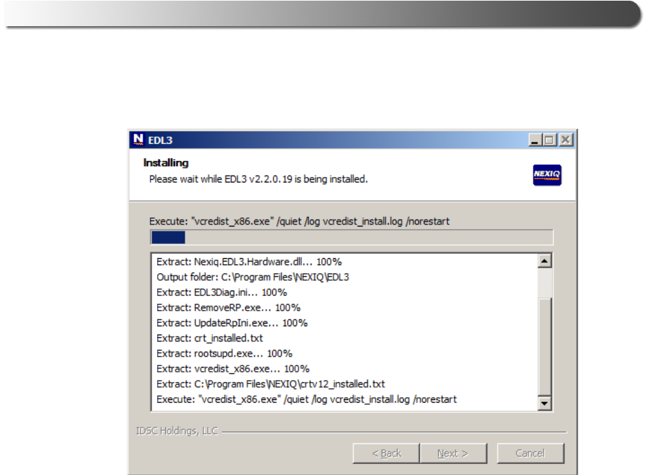
The installation begins and the following screen is displayed.
Figure 3.4 Installation Screen
26 John Deere Electronic Data Link v3 Installation and Setup Manual
Chapter 3 • Installing the Drivers and Setting Up the Device
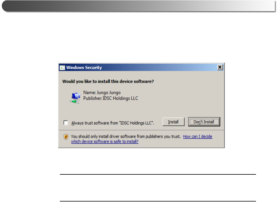
If you are running Windows® 7 or Windows® 8, the following Windows
Security dialog may be displayed.
Figure 3.5 Windows Security Dialog
NOTE:
iYou may want to place a check mark in the Always trust software from
“Jungo LTD” check box. If you leave it unchecked, this dialog may be dis-
played more than once.
8Click Install to continue.
9Wait briefly while the installation continues.
- Step 1: Install the Drivers
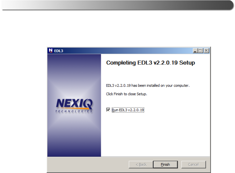
John Deere Electronic Data Link v3 Installation and Setup Manual 27
The following completion screen is displayed.
Figure 3.6 Installation Complete Screen
10 Click Finish.
28 John Deere Electronic Data Link v3 Installation and Setup Manual
Chapter 3 • Installing the Drivers and Setting Up the Device
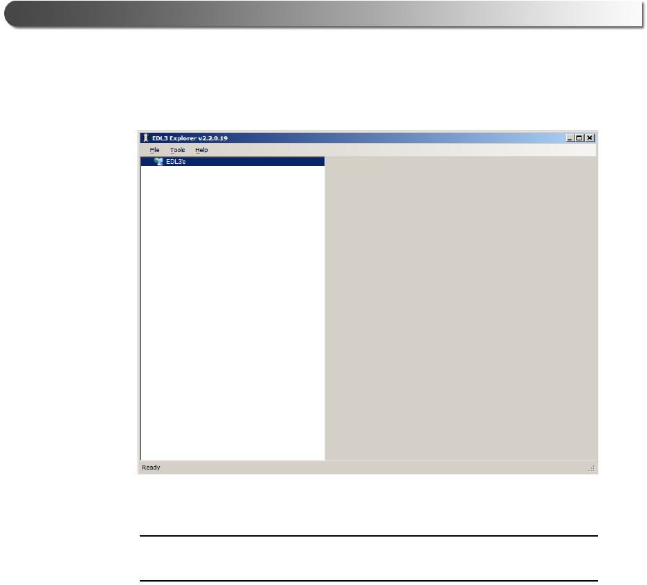
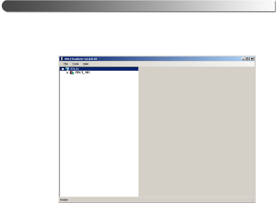
The EDL3 Explorer utility opens.
Figure 3.7 EDL3 Explorer Utility
NOTE:
iFor information on using the EDL3 Explorer, see Using the EDL3 Explorer
Utility on page 43 of this manual.
11 Move on to Step 2: Connect the EDL3 to a Vehicle, next in this manual.

- Step 2: Connect the EDL3 to a Vehicle
John Deere Electronic Data Link v3 Installation and Setup Manual 29
Step 2: Connect the EDL3 to a Vehicle
Once you have installed the EDL3 drivers, you are ready to connect the EDL3 to
a vehicle using an adapter cable. The following adapter is included in the EDL3 kit:
• W1 9-pin Deutsch adapter
Next, you connect the EDL3 to your PC using one of the following options:
•A wired, USB connection (pg. 30)
•A wireless, Bluetooth® connection (pg. 31)
— Connecting via a Class 1, external Bluetooth® adapter
(recommended)
or
— Connecting via Integrated Bluetooth®
•A wireless Wi-Fi connection (pg. 38)
—Mini Access Point Mode (pg. 38)
or
— Infrastructure Mode (pg. 42)

30 John Deere Electronic Data Link v3 Installation and Setup Manual
Chapter 3 • Installing the Drivers and Setting Up the Device
Making a Wired USB Connection
To connect the EDL3 to your PC using a USB cable:
1Connect the USB cable (i.e., an automotive A to Mini-B USB cable) to the USB
port of the PC or laptop.
2Connect the other end of the cable to the port on the bottom of the device.
3Connect the DB26 female end of the appropriate adapter cable to the EDL3.
4Attach the other end of the adapter cable (i.e., the Deutsch connector end) to
the vehicle’s diagnostic connector.
NOTE:
iThe vehicle’s diagnostic connector is typically located under the dash-
board on the driver’s side, or beside the driver’s seat. It can also be
located in the engine compartment, near the electronic control module
(ECM).
Your device is ready to use.

- Step 2: Connect the EDL3 to a Vehicle
John Deere Electronic Data Link v3 Installation and Setup Manual 31
Making a Wireless Bluetooth Connection
NOTE:
iThe EDL3 factory default is Bluetooth® mode in a Non-Discoverable sta-
tus. To confirm that the device is in Bluetooth® mode, press the Reset
button momentarily and the Wireless LED will illuminate blue.
The EDL3 is equipped with a Class 1 Bluetooth® module with a range of up to
100m when communicating with another Class 1 Bluetooth® device. Most PCs
that feature Integrated Bluetooth® are equipped with a Class 2 Bluetooth®
module, which limits the useful range to around 10m.
For maximum wireless range, the use of an external, Class 1 USB Bluetooth®
adapter (sold separately) is recommended.
There are two connection options:
• Connecting via a Class 1, external Bluetooth® adapter (recommended)
• Connecting via Integrated Bluetooth®
The procedure for connecting via Integrated Bluetooth® is much the
same as connecting via an external Bluetooth® adapter. To connect
using your PC’s Integrated Bluetooth®, skip Steps 3 and 4 on page 33
of the following procedure.
Connecting via a Class 1, External Bluetooth Adapter
If you decide to employ an external, Class 1 USB Bluetooth® adapter, you will
have to perform the following tasks:
• Disable your PCs Integrated Bluetooth® device
• Install the drivers supplied with the external adapter, if required
NOTE:
iDepending on the Bluetooth® adapter you are using for your wireless con-
nection, you may need to install the necessary Bluetooth® drivers. For
some adapters the drivers will install automatically.
• Connect the EDL3 to a vehicle
• Pair the EDL3 with your PC (pg. 34)
32 John Deere Electronic Data Link v3 Installation and Setup Manual
Chapter 3 • Installing the Drivers and Setting Up the Device
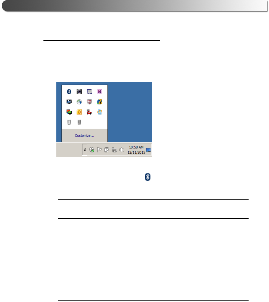
To connect via an external Bluetooth adapter:
1Click on the Show Hidden Icons arrow in your PC’s System Tray.
Figure 3.8 Hidden Icons
The hidden icons are displayed.
2Right-click on the Bluetooth® icon .
NOTE:
iIf your PC has Integrated Bluetooth, skip Steps 3 and 4 and move on to
Step 5.
3Click on Turn Adapter Off (option may not be available in all configurations).
4Plug the Class 1 Bluetooth® adapter you have selected into an available
USB port on your PC, and wait while Windows® installs the required drivers.
NOTE:
iDepending on the Bluetooth® adapter you are using for your wireless con-
nection, you may need to install the necessary Bluetooth® drivers. For
some adapters the drivers will install automatically.
The following message is displayed:
Installing device driver software.
When the installation is complete, the following message is displayed:
Your device is ready to use.

- Step 2: Connect the EDL3 to a Vehicle
John Deere Electronic Data Link v3 Installation and Setup Manual 33
NOTE:
iSome Bluetooth® adapters may require you to configure a Bluetooth®
environment. If this is necessary, an Initial Bluetooth Configuration Wizard
screen will display at the conclusion of the adapter installation process.
If this happens, use the CD that came with the adapter.
5Connect the DB26 female end of the appropriate adapter cable to the EDL3.
6Attach the other end of the adapter cable (i.e., the Deutsch connector end) to
the vehicle’s diagnostic connector.
NOTE:
iThe vehicle’s diagnostic connector is typically located under the dash-
board on the driver’s side, or beside the driver’s seat. It can also be
located in the engine compartment, near the electronic control module
(ECM).
—At this point, the Power LED (green) on the EDL3 should be illuminated
(on).
—If the Power LED is not illuminated, turn the vehicle’s key to the ON posi-
tion, leaving the engine off
7Press and hold the Reset Button until the Wireless LED begins to flash blue
(about 3 seconds).
This will put the EDL3 in Discoverable Mode. When the EDL3 is Discover-
able, a host device can detect, pair, or connect to it. Once a connection is
established, the LED turns solid blue. After two minutes, discoverability will
time out, and the device will go back to Non-Discoverable status.
NOTE:
iSee Device Features in Chapter 2 of this manual for a detailed discussion
of the Reset Button.
8Move on to Pair the Device, next in this manual.
34 John Deere Electronic Data Link v3 Installation and Setup Manual
Chapter 3 • Installing the Drivers and Setting Up the Device
Pair the Device
You use the Windows® utility to pair the device (i.e., the EDL3 with your PC).
To pair the device:
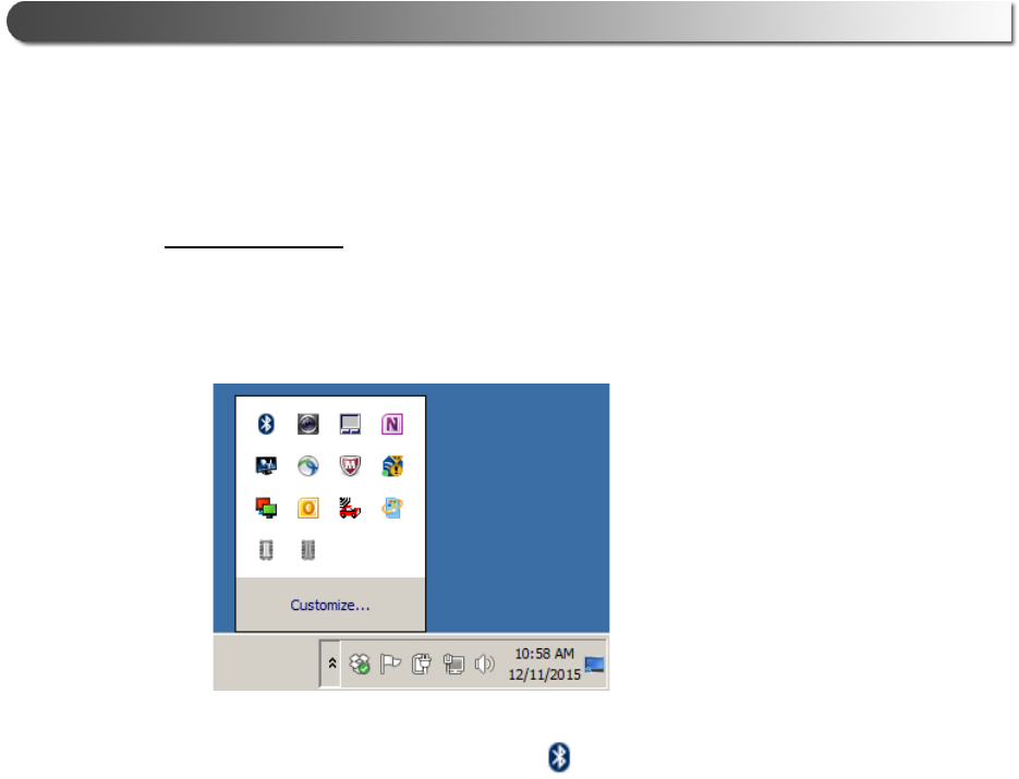
1Click on the Show Hidden Icons arrow in your PC’s System Tray.
Figure 3.9 Hidden Icons
The hidden icons are displayed.
2Right-click on the Bluetooth® icon .
3Click Add a Device.
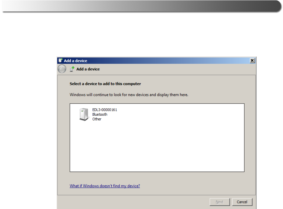
Figure 3.10 Add a Device Screen
- Step 2: Connect the EDL3 to a Vehicle
John Deere Electronic Data Link v3 Installation and Setup Manual 35
The Add a device screen is displayed.
4Select the device displayed that matches the serial number on the back of
your EDL3 (e.g., EDL3_xxxxxx).
36 John Deere Electronic Data Link v3 Installation and Setup Manual
Chapter 3 • Installing the Drivers and Setting Up the Device
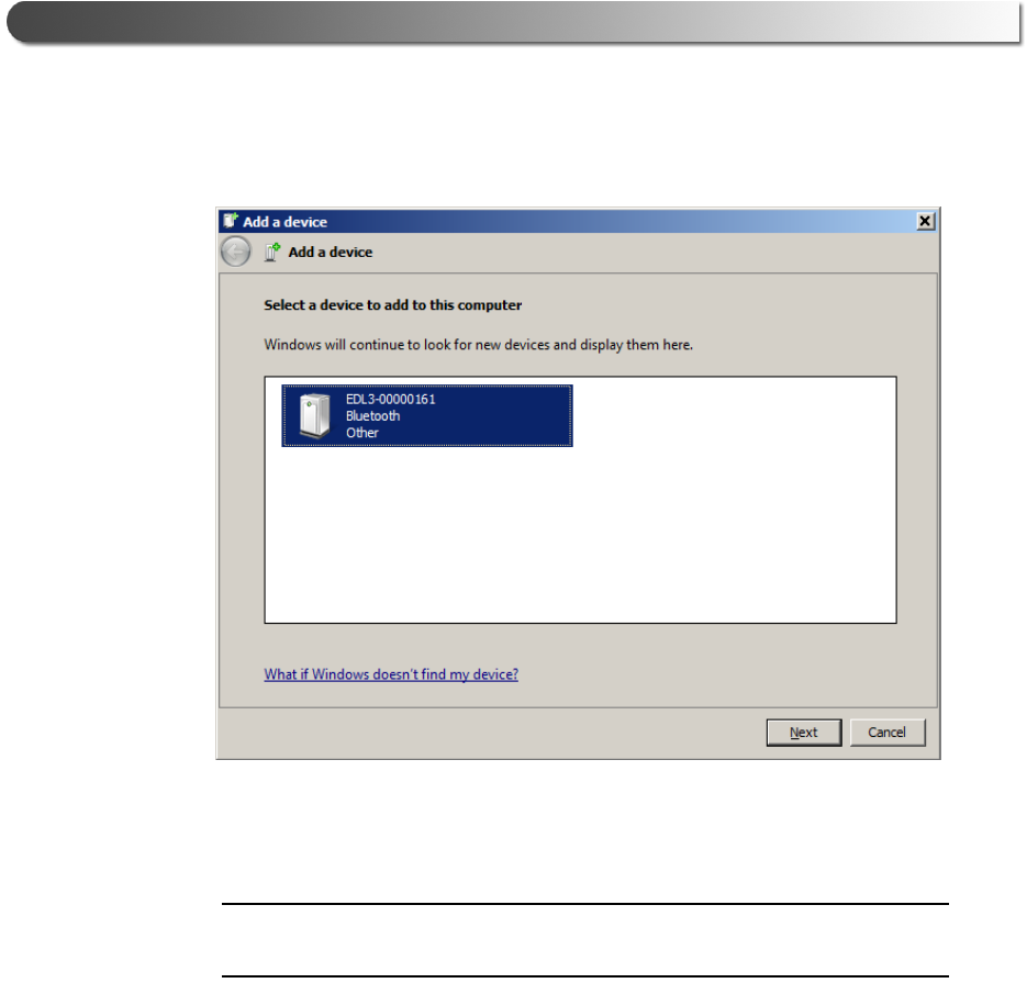
Your selection is highlighted.
Figure 3.11 Add a Device Screen Refreshed
5Click Next.
NOTE:
iYou may be prompted to enter a pairing code for the device. If you are
prompted to enter a PIN or pairing code, enter NEXIQ (all uppercase).
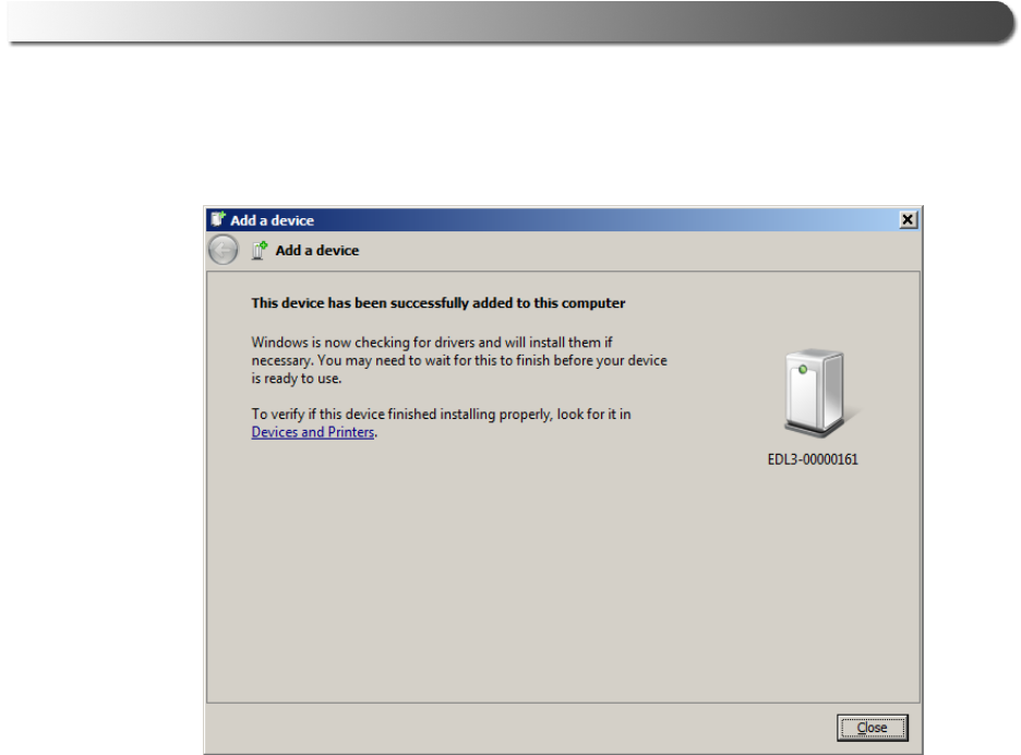
Figure 3.12 Device Successfully Added Screen
- Step 2: Connect the EDL3 to a Vehicle
John Deere Electronic Data Link v3 Installation and Setup Manual 37
The following System Tray message is displayed.
Your device is ready to use.
6Click Close.
38 John Deere Electronic Data Link v3 Installation and Setup Manual
Chapter 3 • Installing the Drivers and Setting Up the Device
Making a Wireless Wi-Fi Connection
When using Wi-Fi, the EDL3 can be configured for either of the following modes:
• Mini Access Point, the Wi-Fi default (pg. 38)
• Infrastructure (pg. 42)
NOTE:
iEDL3 cannot be used in Infrastructure mode until it has been configured
using the EDL3 Explorer utility (see Using the EDL3 Explorer in Chapter 3
of this manual).
Mini Access Point Mode
The easiest and quickest way to connect your EDL3 to your PC is Mini Access
Point mode. In Mini Access Point mode (also known as Access Point Emulation
mode), the PC communicates directly with the EDL3. The EDL3 emulates the
function of an access point, allowing the PC to connect directly to the EDL3, as if
it were an access point. When the PC is connected to the EDL3 in Mini Access
Point mode, neither device is connected to the company network.
Figure 3.13 Mini Access Mode

- Step 2: Connect the EDL3 to a Vehicle
John Deere Electronic Data Link v3 Installation and Setup Manual 39
To connect the EDL3 to your PC using Mini Access Point Mode:
1Connect the DB26 female end of the appropriate adapter cable to the con-
nector on the top of the EDL3.
2Attach the other end of the adapter cable (i.e., the Deutsch connector end) to
the vehicle’s diagnostic connector.
NOTE:
iThe vehicle’s diagnostic connector is typically located under the dash-
board on the driver’s side, or beside the driver’s seat. It can also be
located in the engine compartment, near the electronic control unit (ECU).
—At this point, the Power LED (green) on the EDL3 should be illuminated
(On).
—If the Power LED is not illuminated, turn the vehicle’s key to the ON posi-
tion, leaving the engine Off.
3Press and hold the Reset Button for about ten (10) seconds to switch from
Bluetooth Mode (the factory default) to Mini Access Point Mode.
All of the LEDs on the device will flash momentarily to indicate that the
device has been reconfigured. Once the connection is complete, the
Wireless LED will display white to indicate Wi-Fi Mini Access Point Mode.
NOTE:
iSee Device Features in Chapter 2 of this manual for a detailed discussion
of the Reset Button.
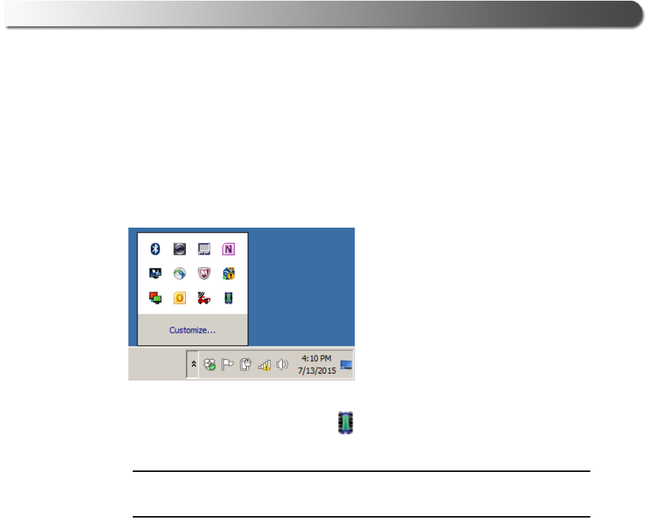
4Navigate to the System Tray on your PC.
Figure 3.14 Windows® System Tray
5Click on the Network icon in the System Tray.
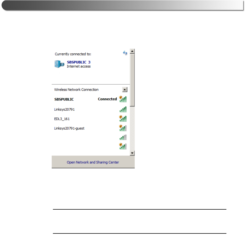
Figure 3.15 Network Selection Screen
40 John Deere Electronic Data Link v3 Installation and Setup Manual
Chapter 3 • Installing the Drivers and Setting Up the Device
The Network Selection screen is displayed.
6Select EDL3_xxxxxx from the list (where xxxxxx is the serial number of the
EDL3).
NOTE:
iIf EDL3_xxxxxx is not displayed, make sure you are connected to the vehi-
cle. Also, make sure you are within range (i.e., within 100 ft.). You may
need to move your PC closer to the vehicle.
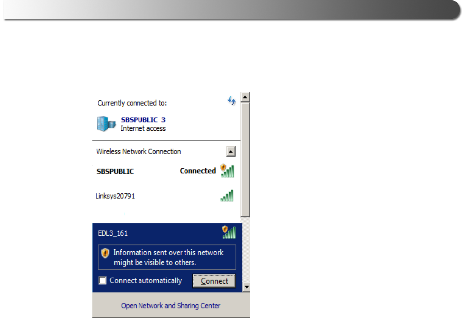
Figure 3.16 Selection Highlighted
- Step 2: Connect the EDL3 to a Vehicle
John Deere Electronic Data Link v3 Installation and Setup Manual 41
EDL3_xxxxxx is highlighted.
7Click Connect.
The device is now connected and ready to use.

42 John Deere Electronic Data Link v3 Installation and Setup Manual
Chapter 3 • Installing the Drivers and Setting Up the Device
Infrastructure Mode
In Infrastructure mode, your PC communicates with your company’s computer
network through a Wireless Access Point (not included), which acts as a bridge
between the wireless network and the wired network. In this mode, the EDL3 is
configured to communicate with the same access point. All communication
between the PC and the EDL3 passes through the access point.
Figure 3.17 Infrastructure Mode
NOTE:
iThe settings for connecting to your company network may differ from one
installation to another. To ensure network security, your Information Tech-
nology (IT) administrator will need to oversee the installation and specify
the appropriate configuration parameters. Your IT administrator should be
able to properly configure the EDL3 for infrastructure mode, using the
EDL3 Explorer utility (see Switching Modes: Mini Access Point and Infra-
structure on page 46 of this manual).
- Using the EDL3 Explorer Utility
John Deere Electronic Data Link v3 Installation and Setup Manual 43
Using the EDL3 Explorer Utility
The EDL3 Explorer utility opened automatically when you installed the EDL3
drivers and utilities (see Figure 3.7, on page 28).
To re-open the EDL3 Explorer once it has been closed, click on the Show Hidden
Icons arrow in your PC’s System Tray.
Figure 3.18 Hidden Icons
Then, double-click on the EDL3 icon 7 .
NOTE:
iYou can also access the EDL3 Explorer from your PC’s Start menu. Click
Start and then select All ProgramsDeere EDL3 EDL3 Explorer.
44 John Deere Electronic Data Link v3 Installation and Setup Manual
Chapter 3 • Installing the Drivers and Setting Up the Device
The EDL3 Explorer opens.
Figure 3.19 EDL3 Explorer
The following menu options are provided:
• File (pg. 48)
•Tools (pg. 49)
•Help (pg. 52)
Each menu option includes a number of features. Each of the menu options
are discussed in the following sub-sections.
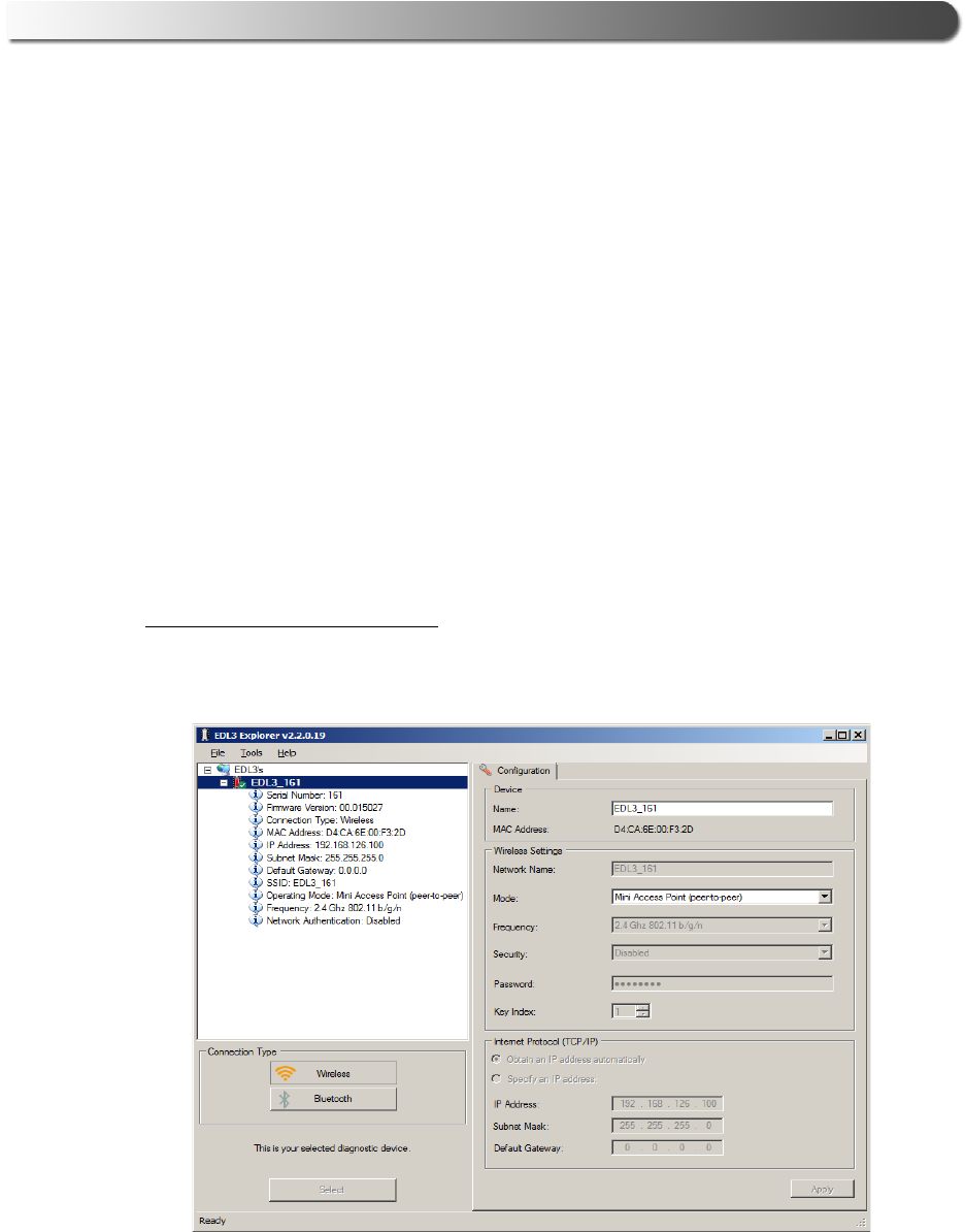
When you click on a EDL3 in the list in the left pane, the Configuration tab is
displayed (Figure 3.20).
- Using the EDL3 Explorer Utility
John Deere Electronic Data Link v3 Installation and Setup Manual 45
The Configuration Tab
The Configuration tab provides the following information:
• Device:
—Name
— MAC Address
• Wireless Settings
• Internet Protocol (TCP/IP) Settings
This information can be useful when troubleshooting network connection prob-
lems. You also use the Configuration tab when switching between the two
wireless Connection Types (i.e., Wireless and Bluetooth), or when setting up a
Wi-Fi connection in Infrastructure Mode.
To access the Configuration tab:
1Click on an EDL3_xxxxxx in the list in the left pane of the Explorer.
Figure 3.20 Configuration Tab
46 John Deere Electronic Data Link v3 Installation and Setup Manual
Chapter 3 • Installing the Drivers and Setting Up the Device
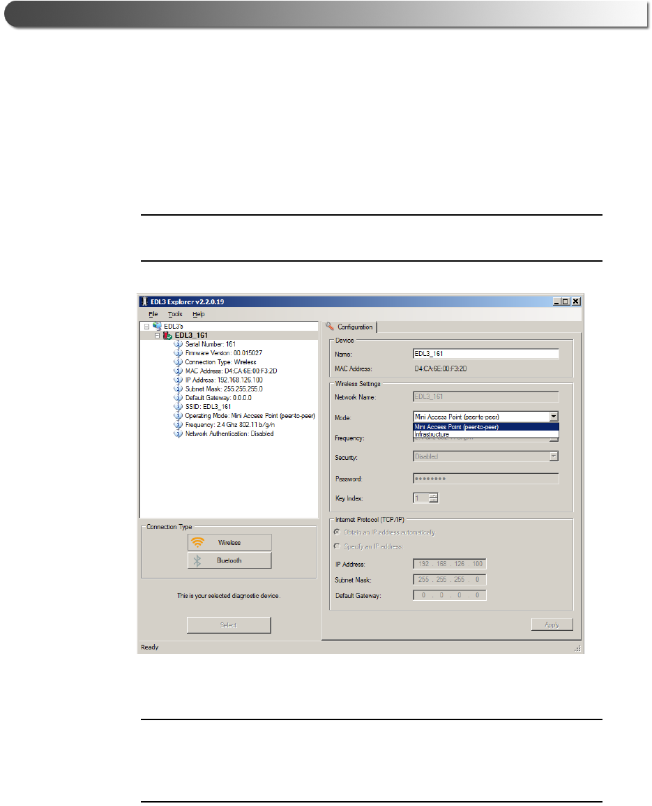
Switching Modes: Mini Access Point and Infrastructure
From the EDL3 Explorer Configuration tab, you can use the Mode drop-
down menu under Wireless Settings to switch between Mini Access Point
and Infrastructure modes.
NOTE:
iFor a graphic depiction of a typical Infrastructure Mode setup, see
Figure 3.17, on page 42.
Figure 3.21 Wireless Settings: Mode Drop-down Menu
NOTE:
iYou can also use the Reset Button to switch from Infrastructure Mode
back to Mini Access Point Mode (the Wi-Fi default). Just push and hold the
button until the wireless LED changes color from orange to white (about 3
seconds).
Once, you have selected Infrastructure from the drop-down menu, addi-
tional fields in the Wireless Settings portion of the screen are available.

- Using the EDL3 Explorer Utility
John Deere Electronic Data Link v3 Installation and Setup Manual 47
The following Wireless Settings fields are available:
• Network Name
• Frequency (used to switch between 2.4 and 5 GHz)
• Security (WEP, WPA/WPA2)
• Password
• Key Index (only available with the WEP security selection)
NOTE:
iThe settings for connecting to your company network may differ from one
installation to another. To ensure network security, your Information Tech-
nology (IT) administrator will need to oversee the installation and specify
the appropriate configuration parameters.
The Internet Protocol (TCP/IP) portion of the screen is also available to
you to enter the required settings. There are two options:
• Obtain an IP address automatically (i.e., a dynamic IP address)
• Specify an IP address (i.e., a static IP address that does not change)
— IP Address
— Subnet Mask
— Default Gateway
NOTE:
iYou will need to obtain this information (i.e., IP Address, Subnet Mask)
from the designated IT person or network administrator for your location.
Depending on how your local network is configured, you may also need to
enter Default Gateway information.
48 John Deere Electronic Data Link v3 Installation and Setup Manual
Chapter 3 • Installing the Drivers and Setting Up the Device
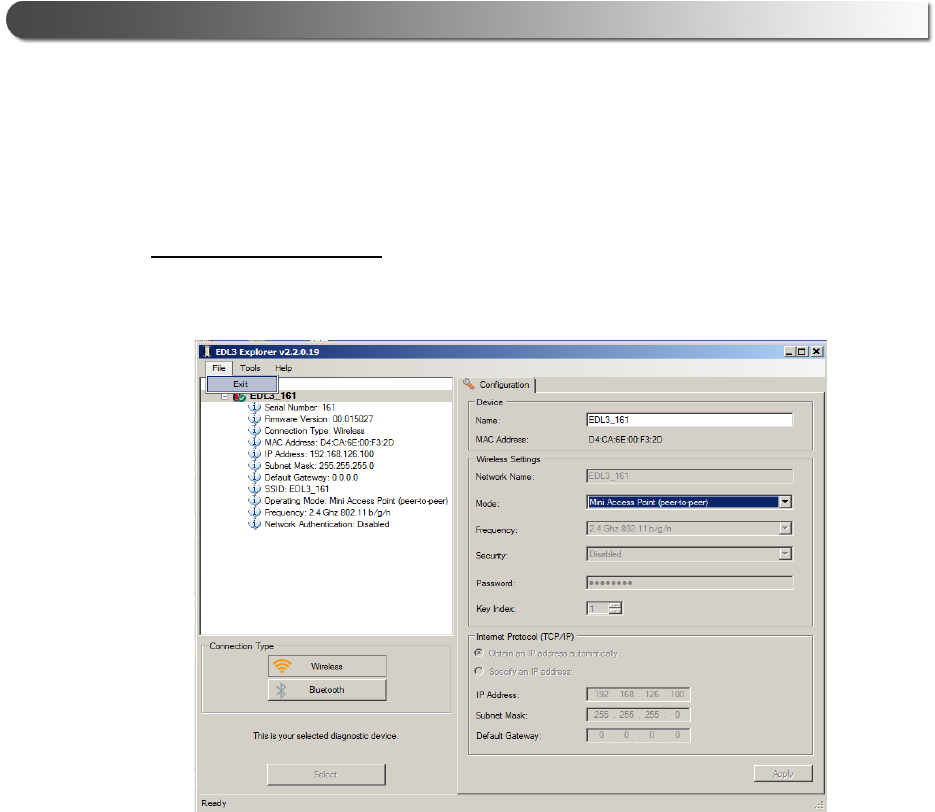
The File Menu
The File menu has one feature, Exit. You use the Exit feature to close the EDL3
Explorer.
To exit the EDL3 Explorer:
1Select File from the EDL3 Explorer menu bar.
Figure 3.22 Exit Selected
2Select Exit.
The EDL3 Explorer closes.
- Using the EDL3 Explorer Utility
John Deere Electronic Data Link v3 Installation and Setup Manual 49
The Tools Menu
The Tools menu provides the following features:
•Ping
•Options
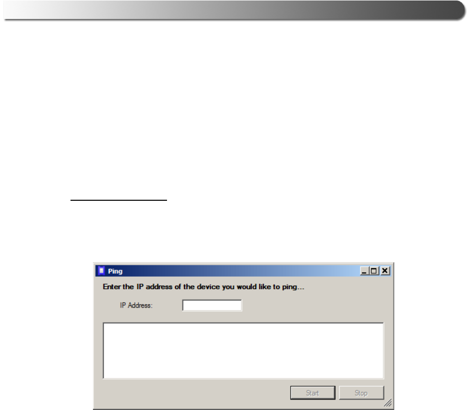
Ping
The Ping feature uses the PING protocol to check for the presence of a device on
the network.
To check for a device:
1Select Tools from the EDL3 Explorer menu bar.
2Select Ping.
Figure 3.23 Ping Dialog Box
3Enter the IP address of the device you want to locate (e.g., 192.168.123.107).
4Click Start.
The EDL3 Explorer searches for the device and, if found, displays the reply.
5Click Stop.
6Click the Close button on the dialog box.
50 John Deere Electronic Data Link v3 Installation and Setup Manual
Chapter 3 • Installing the Drivers and Setting Up the Device
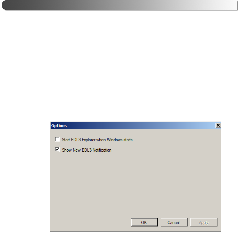
Options
The Options feature provides the following features, which are presented as check
boxes:
• Start EDL3 Explorer when Windows starts (pg. 50)
• Show New EDL3 Notification (pg. 51)
Start EDL3 Explorer when Windows Starts
You use this feature to manage when the EDL3 Explorer opens.
The default is to not open the EDL3 Explorer when Windows starts.
Figure 3.24 Options Menu
To change the default, click on the check box to add the check mark. Then click
OK.
- Using the EDL3 Explorer Utility
John Deere Electronic Data Link v3 Installation and Setup Manual 51
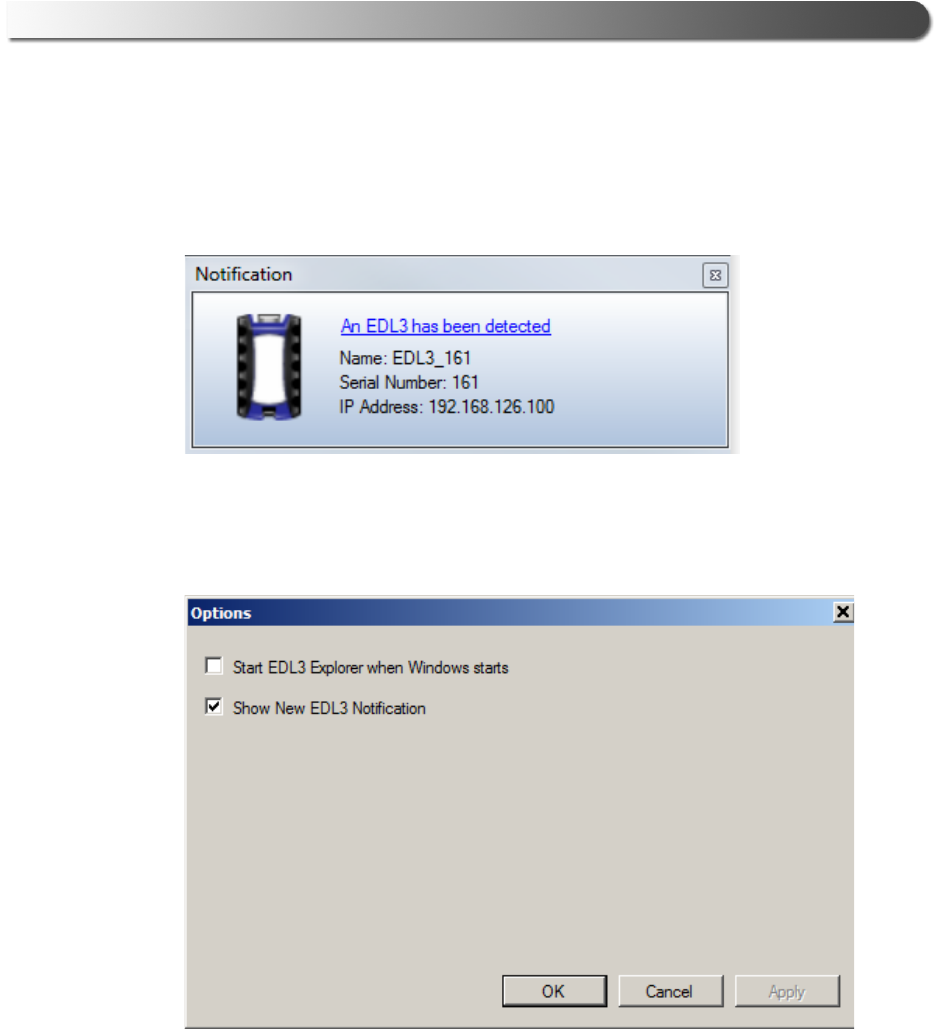
Show New EDL3 Notification
You use this feature to manage when to display the New INLINE7 notification
message box.
Figure 3.25 Notification Box
The default is to display the notification message box whenever a new EDL3 is
detected.
Figure 3.26 Options Menu
To change the default, click the box to remove the check mark. Then click OK.
52 John Deere Electronic Data Link v3 Installation and Setup Manual
Chapter 3 • Installing the Drivers and Setting Up the Device
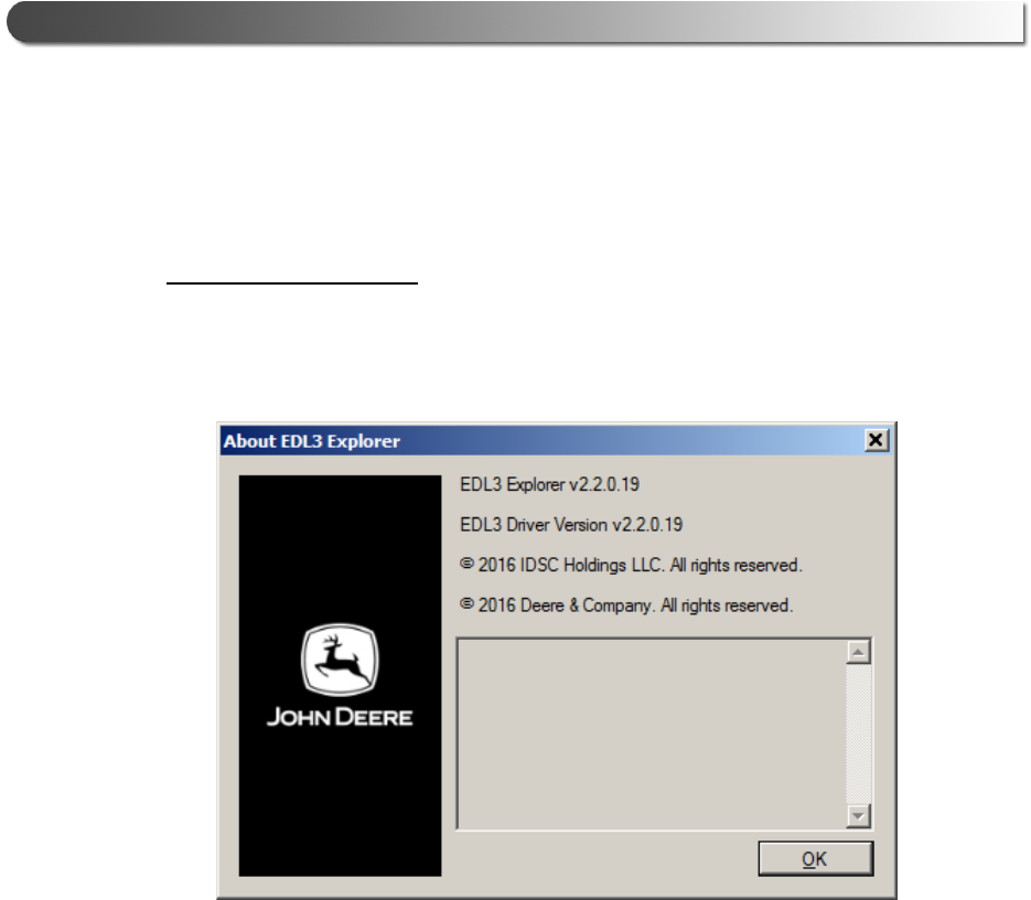
The Help Menu
The Help menu has one feature, About. You use the About feature to display in-
formation about the EDL3 Explorer.
To access the Help menu:
1Select Help from the EDL3 Explorer menu bar.
2Select About.
Figure 3.27 About EDL3 Explorer
3When you have finished reviewing the information, click OK to close the
dialog box.