Users Manual
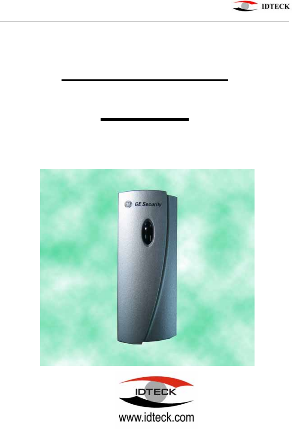
GE616 PROXIMITY READER
USER’S MANUAL
GE616
V5.2.0
Proximity Reader
MANUAL 20050308 - 1 - GE616

GE616 PROXIMITY READER
CONTENTS
1. Introduction page 3
2. Identifying supplied parts page 3
3. Specification page 3
4. Installation page 4
5. Wire Color Table of the Reader page 5
6. Wire Connection to Controller page 5
7. Operation page 6
8. FCC Registration Information page 7
9. Warranty and Service page 8
MANUAL 20050308 - 2 - GE616
GE616 PROXIMITY READER
1. Introduction
The GE616 is an elegant looking and an attractive 4" read range proximity reader which can be
mounted to metal door frame(mullion) or any flat wall surface. The GE616 use the same electronics
module in epoxy potting that ensure you successful operation even in harsh environments. The
different bezels allow you to interchange the bezel for different applications or wall conditions.
Two color LED of green and red, inside Piezo buzzer sound will guarantee you an accurate and reliable
system operations.
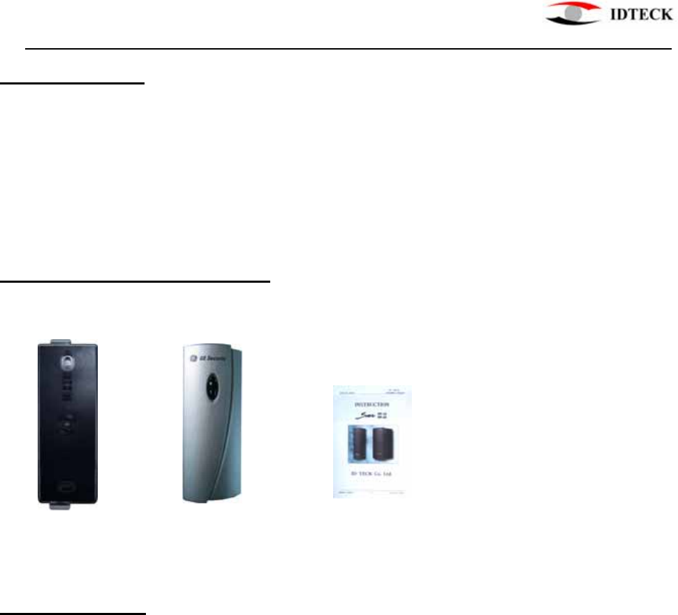
2. Identifying supplied parts
Please unpack and check the contents of the box.
Reader Module GE616 Bezel Instruction
(1 ea) (1 ea) (1 ea)
3. Specification
Read Range/Time Up to 4"(10cm) / 30ms
Input Voltage/Current DC 5V ~ 17V, Max. 180mA
Output Format 26 bit Wiegand, ABA Track II, RS232C
External Buzzer control Input Low Active, DC 0 ~ 12V, Max. 50 mA
External LED control Input Low Active, DC 0 ~ 12V, Max. 50 mA
LED/Buzzer 2 Color LED(Red and Green) / Piezo Buzzer
Color Dark Pearl Gray
Operating Environment -31℉ ~ 149℉(-35℃ ~ +65℃), 0~90% Humidity
Overall Size(WxHxD) GE616 : 1.82"x4.81"x0.87"(46x122x23mm)
RF-20 : 3.00"x4.89"x0.87"(76x124x23.5mm
Weight 0.35lb(160g)
MANUAL 20050308 - 3 - GE616
GE616 PROXIMITY READER
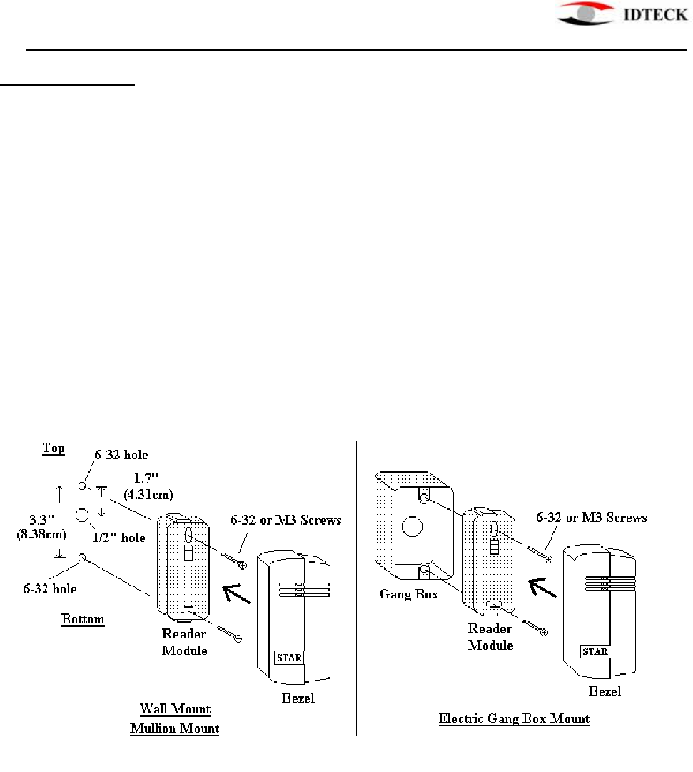
4. Installation
4-1. Mullion/Wall Mount
Drill two 6-32 or M3 holes 3.3"(8.38cm) apart in vertical and drill one 1/2" hole for
the reader cable 1.7"(4.31cm) apart from the top hole.
(If you have installed electric gang box then skip this step.)
4-2. Put reader cable into the center hole and install the reader module by using two
6-32 or M3 screws.
4-3. Put bezel into the reader module then push bezel until you hear the locking sound.
MANUAL 20050308 - 4 - GE616
GE616 PROXIMITY READER
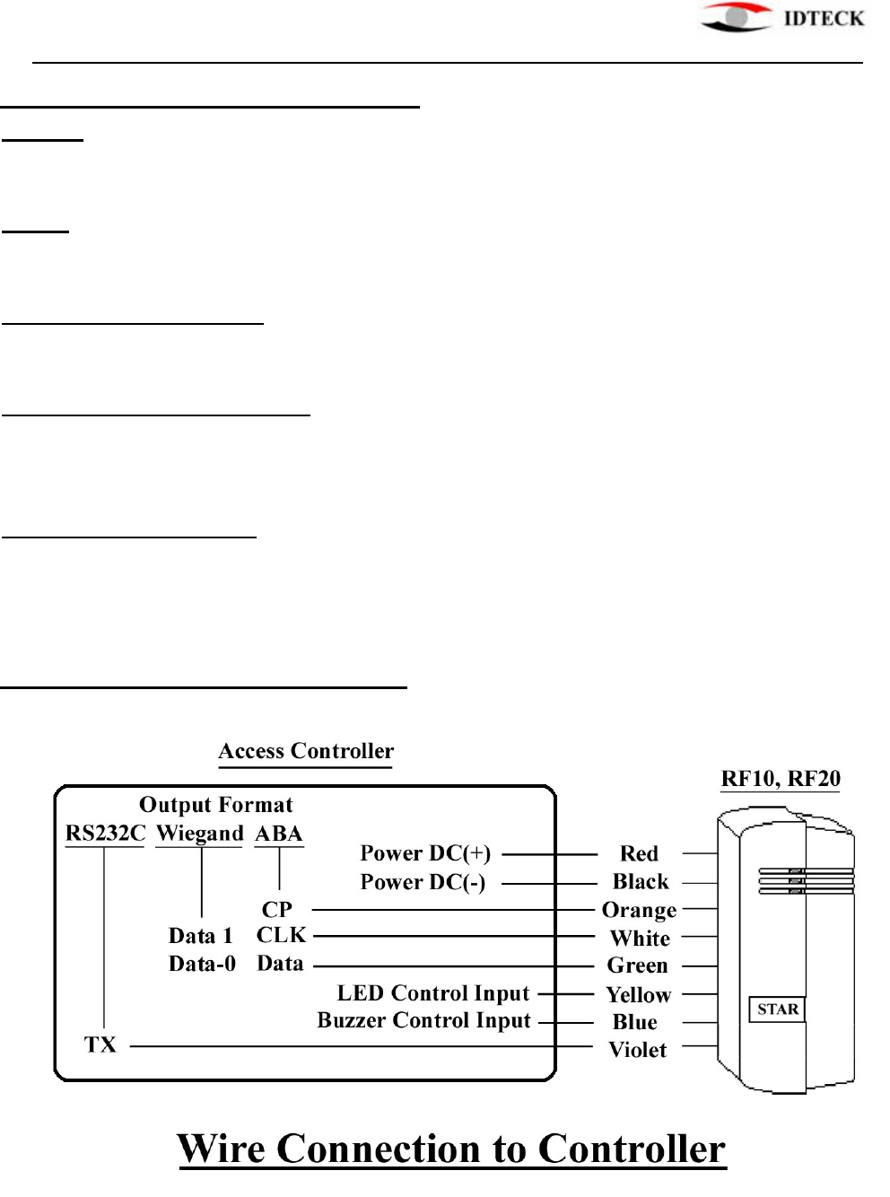
5. Wire Color Table of the Reader
POWER
Power(DC +5V~+17V) DC(+) Red wire
Power(DC Ground) DC(-)(GND) Black wire
INPUT
Buzzer control input BUZZER Blue wire
LED control input LED Yellow wire
OUTPUT(Wiegand Format)
Wiegand Data-0 Data-0 Green wire
Wiegand Data-1 Data-1 White wire
OUTPUT(ABA Track II Format)
ABA(Card Present) CP Orange wire
ABA(Clock) CLK White wire
ABA(DATA) Data Green wire
OUTPUT(RS232C Format)
RS232C(TX) TX Violet wire
6. Wire Connection to Controller
MANUAL 20050308 - 5 - GE616

GE616 PROXIMITY READER
7. Operation
7-1. Apply power and you can see Red LED is on indicating the reader is in standby.
7-2. Present proximity card to the reader until you hear beep sound and the LED is
changing the color to Green simultaneously and the reader send RF card data to the
controller then LED changes the color to Red again for next reading.
7-3. LED Control;
To change the LED colors, you may connect LED Control Input(Yellow wire) to
power ground then the Green LED is on indicating the reader is in standby.
Present proximity card then the LED changes the color to Red simultaneously then
Green again for next reading.
7-4. Buzzer Control;
When the reader reads proximity card, only one beep sound generates in normal
operating mode but you can generate more beep sounds to distinguish whether the
access is granted or denied.
To generate more beeps, you may control the Buzzer Control Input(Blue wire) to power ground
then you can turn beeper on while you hold Buzzer Control Input to power ground.
MANUAL 20050308 - 6 - GE616

GE616 PROXIMITY READER
8. FCC REGISTRATION INFORMATION
FCC REQUIREMENTS PART 15
Caution: Any changes or modifications in construction of this device which are not expressly approved by the responsible
for compliance could void the user's authority to operate the equipment.
NOTE: This device complies with Part 15 of the FCC Rules.
Operation is subject to the following two conditions;
1. This device may not cause harmful interface, and
2. This device must accept any interference received, including interference that may cause undesired
operation.
This equipment has been tested and found to comply with the limits for a Class A Digital Device, pursuant to Part 15 of
the FCC Rules. These limits are designed to this equipment generates, uses, and can radiate radio frequency energy and, if
not installed and used in accordance with the instructions, may cause harmful interference to radio communications.
However, there is no guarantee that interference will not occur in a particular installation. If this equipment does cause
harmful interference to radio or television reception, which can be determined by turning the radio or television off and on,
the user is encouraged to try to correct interference by one or more of the following measures.
1. Reorient or relocate the receiving antenna.
2. Increase the separation between the equipment and receiver.
3. Connect the equipment into an outlet on another circuit.
4. Consult the dealer or an experienced radio/TV technician for help.
MANUAL 20050308 - 7 - GE616

GE616 PROXIMITY READER
9. Warranty and Service
The following warranty and service information applies only to the United States of America and Republic of Korea. For
the information in other countries, please contact your local distributor.
To obtain in or out of warranty service, please prepay shipment and return the unit to the appropriate facility listed below.
IN THE UNITED STATES
RF LOGICS Inc. Service Center
3026 Scott Blvd.,
SANTA CLARA, CA95054
Tel.: (408) 980-0001
Fax.: (408) 980-8060
E-mail: rflogics@rflogics.com
Web-site: www.rflogics.com
OUTSIDE OF THE UNITED STATES
ID TECK CO., LTD. Service Center
5F Ace Techno Tower Bldg.,
684-1 Deungchon-dong, Gangsuh-gu,
SEOUL 157-030, KOREA
Tel.: +82 (2) 2659-0055
Fax.: +82 (2)2 659-0086
E-mail: webmaster@idteck.com
Web-site: www.idteck.com
Please use the original container, or pack the unit(s) in a sturdy carton with sufficient packing to prevent damage, include
the following information:
1. A proof-of-purchase indicating model number and date of purchase.
2. Bill-to address
3. Ship-to address
4. Number and description of units shipped.
5. Name and telephone number of person to contact.
6. Reason for return and description of the problem.
NOTE: Damage occurring during shipment is deemed the responsibility of the carrier, and claims should be made directly
to the carrier.
MANUAL 20050308 - 8 - GE616