Contents
- 1. USERS MANUAL 1
- 2. USERS MANUAL 2
USERS MANUAL 1

Notice
Copyright
VIP Systems hold copyright of this manual, which is protected by the
Copyright Act.
Therefore, without previous permission of VIP Systems, any part of this
manual may not be copied in any way of machinery, electronics, or any
method.
The contents of this manual could be changed without previous notice
for a reason of trust, improvement of design and function, etc.
Manufacturing company does not guarantee loss regarding data. Therefore,
take care of important data not to be lost, and always back up them.
Although this manual was written making assurance doubly sure, manufa
cturing company and supplier do not assume the responsibility for the result
caused by an error, omitted contents of this manual.
Registered in Electromagnetic compatibility(Class B)
This product was registered in electromagnetic compatibility(Class B).
you can use it safely at any place.
NOTE: This equipment has been tested and found to comply with the limits for a Class
B digital device, pursuant to Part 15 of the FCC Rules. These limits are designed to
provide reasonable protection against harmful interference in a residential installation.
This equipment generates, uses and can radiate radio frequency energy and, if not
installed and used in accordance with the instructions, may cause harmful interference
to radio communications.
However, there is no guarantee that interference will not occur in a particular
installation. If this equipment does cause harmful interference to radio or television
reception, which can be determined by turning the equipment off and on, the user is
encouraged to try to correct the interference by one or more of the following measures:
-- Reorient or relocate the receiving antenna.
-- Increase the separation between the equipment and receiver.
-- Connect the equipment into an outlet on a circuit different from that to which the
receiver is connected.
-- Consult the dealer or an experienced radio/TV technician for help.
THIS DEVICE COMPLIES WITH PART 15 OF THE FCC RULES.
OPERATION IS SUBJECT TO THE FOLLOWING TWO CONDITIONS:
(1) THIS DEVICE MAY NOT CAUSE HARMFUL INTERFERENCE, AND
(2) THIS DEVICE MUST ACCEPT ANY INTERFERENCE RECEIVED,
INCLUDING INTERFERENCE THAT MAY CAUSE UNDESIRED OPERATION
THE MANUFACTURER IS NOT RESPONSIBLE FOR ANY RADIO OR TV
INTERFERENCE CAUSED UNAUTHORIZED MODIFICATIONS TO THIS EQUIPMENT.
SUCH MODIFICATIONS COULD VOID THE USER'S AUTHORITY TO OPERATE THE
EQUIPMENT.

Suggestions
For right and safe set up and use of this product, please read this user's manual
carefully in advance.
Safety device is already installed in this product to prevent user's injury, but
pay regard to the following details for safe use.
Suggestions when installing
Prevent injury or damage of product by installing on the safe place(on the firm
and even surface)
Install at a place of good ventilation for preventing over moisture and
overheating.
Install away from magnetic objects.
Confirm where voltage used is appropriate when connecting to power source.
For AC adapter and power source cord, use belongings wrapped up with the
product, and do not put heavy stuff on them.
To prevent danger of an electric shock and fire, do not use damaged consent
or the one that is insufficient for standard.
If you connect power source cord to extended cord, make sure that electric
current of every equipments connected to extended cord is less than standard
value stated on extended cord.
Suggestions for use
In case peripheral instruments are connected to this product, turn on
peripheral instruments first when approving power source, and turn off this
product first when cutting off power source to prevent damage of product.
Make sure that any liquid should not get in to this product. It may cause damage
of product, fire, or electric shock.
When cleaning of this product, separate AC adapter before wiping, and never
use liquid or spray detergent. Wipe it using paper or cloth wetted with
exclusive detergent for computers.
When the product is not used for a long time, separate it from the main
power source consent to prevent damage caused by excessive electric current.
To pull out power source cord, grip plug firmly rather than pulling the line.
Do not leave this product at a place where ventilation is bad, and temperature
is over 60 (140 ), which may damage the product.

Maximum temperature at which this product can operate normally is 35 ,
so keep it away from electric range including heater.
Pay attention not to damage hard disk data built in this product, and please
always back up important data for preventing the worst case.
Do not take this product to pieces at your will. For safety, only qualified
service staff can dismantle repair and convert.
If the following situations happen, please inquire of service staff about
those matters for inspections.
In case liquid gets into the product, or it is exposed to moisture.
In case a product does not operate well, or you can not operate it according
to user's manual.
In case product is damaged or there is distinct damage by dropping.

Notice
Suggestions
Contents
Chapter 1 Introduction
Undo a product package
Chapter 2 Look into computer
computer rear side(connecting part of connectors)
Chapter 3 C o mputer se tting ch ange
BIOS setup utility
OSD(On Screen Display) program
System upgrade
Chapter 4 R e installing co mputer
Reinstalling windows XP
Installing TV driver, program
Installing touch screen program and setup
Chapter 5 U s ing co mputer
Using windows XP Home Edition
TV User's Guide
1
2
4
5
5
7
8
9
9
13
14
15
15
16
28
28
28
30
Contents

Congraturation on your purchase of eSTATION ALL-In-On PC.
Characteristics of product
Estation is one body PC of 15 inch TFT-LCD monitor and desktop PC. And it
harmonizes with any working environment due to ultra light weight(5.7 Kg)
and polished design of space-saving type. Furthermore, in case of separating
stand and applying exclusive adapter, you can use it as wall mounted.
Because necessary main function is built in the body so that anyone can use
easily by connecting power source cord. It adjusts to various working envir
onment of user, and supports not only the existing all kinds of peripheral
instruments, but also PCMCIA card slot, USB port, IEEE1304 adapter, TV
tuner/capture function(option), etc.
To rebuilt, the newest peripheral instruments can be used through built
in network adapter, wire networking is possible without installing
additional devices. And it supports to be able to operate wireless networking by
using PCMCIA wireless lan card, which improves office working environment,
maintenance, and mobility.
Because it supports Window XP, the latest operation system of Microsoft, more
safe and faster computing environment is provided.
By adopting 15 inch TFT-LCD monitor, harmful electron is wave and electricity
used is minimized, and it prevents eye fatigue even while using for the long
time.
Chapter 1 Introduction

Undo product package
This p roduct is s afely w rapped u p in f irm c ardboard p aper b ox .
The f ollowing g oods s houldb e included in t he b ox.
15 inch TFT-LCD monitor one body type PC main body
network adapter(RealTek RTL8130C Ethernet-based 10/100Mbps, basic built in)
PCMCIA(PC) card slot(Type / support, basic built in)
Combined use of 110/220V AC/DC adadpter
AC power source cord
Combo cable(for 2 serial communication devices and printer connection)
CD for installing Microsoft operating system and user's manual
eSTATION user's manual(this pamphlet)
Touch screen CD, TV Install program
TV tuner(main body built in type)
adapter for wall tapestry
Basic optional equipment
It supports USB booting function through USB device. The following devices
support this function.
USB floppy disk device
- manufacturing company : YEDATA
- model name : YD-8U10
USB CD-ROM or CD-R/RW device
- manufacturing company: Sarotech, Corp.(http://www.sarotech.om)
- model name: NCD-241IU/NCR-882U2
Other peripheral equipment
This product supports the following other peripheral equipment at the same
time.
Printer(LPT1)
Serial communication devices(COM1)
USB devices(USB 1.1 support)
IEEE 1394 device
PCMCIA(PC) card
External speaker
External mike
External A/V device
Touch screen
This chapter briefly explains about the exterior of computer, all kinds of buttons,
LED display, and additional linking device.
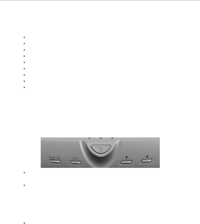
Computer front side(control part)
Power button
- Power: it turns on/off the power source of computer(TFT-LCD monitor and body)
Control button for monitor OSD(ON Screen Display) control
- MENU: it is used to end or call main menu, and to end after saving current control
valve on control screen of each relevant item.
- SEL: it is used to select appropriate item on main menu/sub menu screen.
- Up/Down: it is used to move for selecting appropriate item on main menu/sub menu
screen, or to move to desired control valve from control screen of the selected item.
LED indicator light
- ACTIVE: it indicates data being transmitted and received through network line.
- HDD: it indicates computer is recognizing HDD.
- POWER: it indicates power is authorized on computer.
Chapter 2 Look into computer
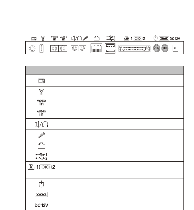
Computer rear side(connecting part of connectors)
antenna cable for TV
IEEE 1394
video input terminal of the exterior AV device
Link
Link
Link video input terminal of the exterior AV device
Link the exterior speaker device or headphone
Link the exterior mike device
Link 10/100 Mbps ethernet(LAN) cable
Link USB device(possible to link 2 at the same time)
Link combo cable (2 serial/LPT 1)
it does not support com port due to use of touch screen
PS/2 mouse link
PS/2 keyboard link
AC/DC adapter link
Linking device
Icon

Chapter 3 Computer setting change
This chapter shows how to change to be suited for use r environment in brief by
using BIOS set up utility th an can change environment of system and OS D/(On
Screen Display) that can change screen set ting of LCD monitor.
In addition. it explains about system upgrade.
BIOS set up utility
For this product, BIOS based on the newe st Phoenix BIOS 4.0 version of Phoen ix
Technology, Inc. is applied, and for each envir onment variable, system environment
value which is the best suite d to this product is applied as def ault.
Furthermore, because it provides BIOS set up utility that use rs can change system
environment at their will, users can change sy stem environment variable for their
environment. In particular, it is used when ch anging booting order, setting password,
etc. or adding new device, But, beware that if you set BIO S set up wrongly, system
error could happen.
[Reference]
BIOS set up is an operatio n that sets up appropria tely and stores hardware
constituent content of system. Set up conte nts is saved CMOS RAM within system,
so it is stored by the inside batter y even when power get turn ed off.
How to change BIOS setting
It explains shortly regarding how to change set up by using BIOS set up utility.
1. Turn on your computer.
2. If booting screen appears, press <F2> button to operate BIOS set up utili ty. IF
you press <F2> button too late at this time , window is booted, so press < F2>
button again restarting com puter.
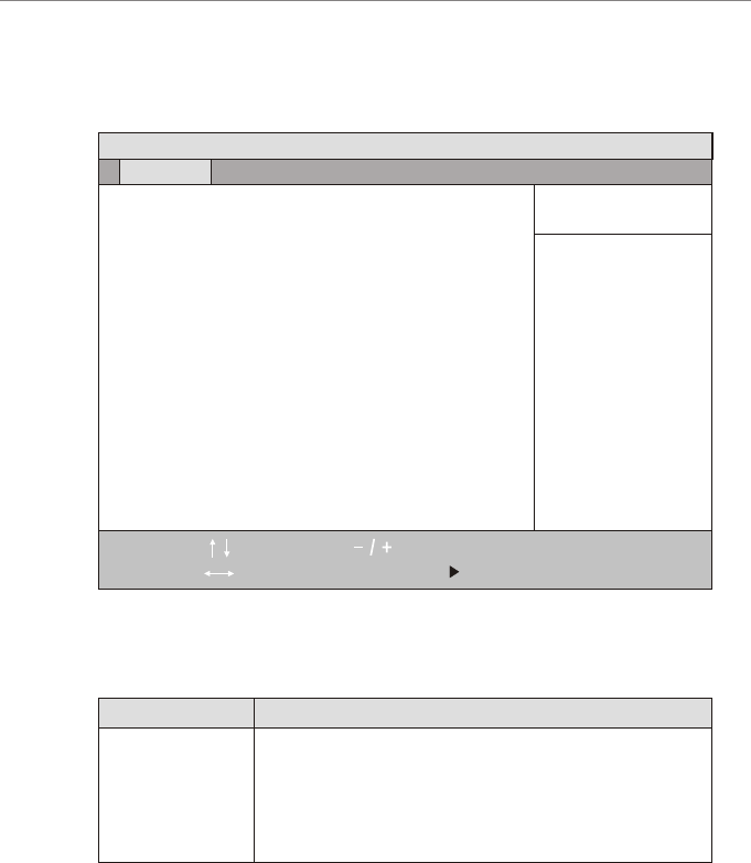
PhoenixBIOS set up utility provides 5 menus.
PhoenixBIOS set up utility provides 5 menus.
Main menu
Advanced menu
Power menu
Boot menu
Exit menu
System Time
System Date
Legacy Diskette A :
Primary Master
Primary Slave
Secondary Master
Secondary Slave
System Memory
Extended Menory
[09:43:29]
[03/16/2002]
[Disabled]
[FUJITSU MHK2060AT]
[None]
[None]
[None]
640 KB
129024 KB
PhoenixBIOS Setup Utility
You can see the basic spec of computer or change set up.
You can set up regarding main chipset, peripheral, etc.
You can set up regarding power mode.
You can set up changing booting order.
You can set up regarding set up exit.
Main Advanced Power Boot Exit
Help
Exit
F1
Esc EnterEnter
F9
F10
Select Item
Select Menu
Change Values
Select Sub-Menu
Setup Defaults
Save and Exit
Explanation of Menu
Menu
<Tad>, <Shift-Tab>, or
<Enter> selects fields
Item Specific Help

4. Change setup using keyboard.
Each key and its function of keyboard that is used to change setup are as
follows.
To use help
To move menu
To move item
To changevalu e ofitem
To enter intosubmen u
To move fromsubmen u to
upper menu
To restoreinit ialvalu e which
set in fromfact ory.
To end savethecha nged
value.
Press <F1> key.
Use left and right arrow keys
Use up and down arrow keys
Use+and - keys. For help to each item, please
refer tohel p appearing ontherig htsideof screen.
Press
<enter>ke y.Itemwi th mark indicates
there issub menu.
Press <Esc>ke y.
Press <F9>key .
Press <F10>ke y.
5. To end setup saving every changed contents in CMOS RAM, press <F10> key.
Then system will be rebooted with the changed contents.
How to boot a system with USB device.
This product is able to boot a system by using USB FDD and USB CD-ROM
drive in 'basic optional equipment' of Chapter 1 Introduction.
1. Execute PhoenixBIOS set up utility.
2. Move from PhoenixBIOS set up utility main menu screen to advanced menu.
3. After a while, PhoenixBIOS set up utility main menu screen will appear as
follows.
Function How to use keyboard
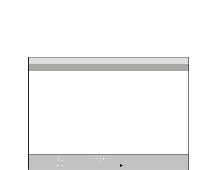
3. Move to Advanced Chipset Control item from Advanced menu, and press
<Enter> key, that enter into Advanced chipset Control sub menu screen.
4. Move to from Advanced chipset Control sub menu screen to Legacy USB
support item, and change the value as [Enabled].
5. To move from Advanced chipset Control sub menu to the upper level,
Advanced menu, press <Esc> key.
6. After moving from Advanced menu to Boot menu, in case of booting as
USB FDD in booting order, change for Removable Devices to be placed at
top level, and in case of booting as USB CD -ROM, change for CD-ROM
Drive to be placed at top level.
7. To end set up after saving changed contents in CMOS RAM, press <F10>
key. Then, system is booted with USB device which system is connected.
Video boot type
Video BIOS Update
Video BIOS
Enable memory gep :
Enable CD hole
Frequency Ratio
Legacy USE Support
[Onboard Video 1 MB]
[Enabled]
[Default VB]
[Disabled]
[]Disabled
[2X]
[Enabled]
PhoenixBIOS Setup Utility
Advanced
Advance Chipset Control
Help
Exit
F1
Esc EnterEnter
F9
F10
Select Item
Select Menu
Change Values
Select Sub-Menu
Setup Defaults
Save and Exit
Enable support for
Legacy Universal Serial
Bus
Item Specific Help

OSD(On Screen Display) program
For LCD monitor of this product, 15 inch TFT-LCD smart panel is applied,
and it also provides standard OSD program for user to be able to change
screen setting
[Reference]
OSD program means screen control program of monitor, and user can
control with their desired value about the following items.
Brightness control
Contrast
Position control ; H-Position / V-Position / Phase / Clock
Auto-Adjustment
Language select ; English / French / Deutsch / Italian / Spanish
Color control
OSD Adjust ; Display Position / Display Time
Information ; Resolution, Horizontal & Vertical frequencies
How to operate OSD program
It explains briefly about how to operate OSD program.
1. With computer turned on, press <MENU> key on control part of
computer in front side.
2. When OSD main menu screen appears, move to the icon indicating items
that you want to control by using <up( )> / <down( )> key, and then
press
<SEL> key.
3. In case there is sub menu in the selected item, move to the relevant item
by using <up( )> / <down( )> key, and then press <SEL> key.
4. If the control screen regarding the relevant item appears, change it into
desired value by using <up( )> / <down( )> key, and then press
<MENU> key. Then the relevant item is saved as the changed value, and
returned to OSD menu(main or sub menu) screen.
5. When control is completed, press <MENU> key on OSD main menu screen to
end OSD program.

System upgrade
Hardware upgrade
This product does not guarantee in case that user personally upgrade a
system for user safety and normal operation of system.
If you take a computer to pieces at random, computer could be damaged a
lot, and there is danger of electric shock.
Therefore, if you would like to install new TV tuner, or upgrade CPU, hard
disk or memory, please make inquires of ESTATION center.
The newest version of each manufacturing company is installed regarding
basic driver and application program when shipping from factory. However,
because each manufacturing company continues to present improved version
for customers, please visit the following site regularly about main software in
stalled previously to this product so you can upgrade with the newest version.
Microsoft Corporation Windows XP Home Edition.
810E chipset software installation utility, video driver, and capacity
improving utility of Intel Corporation.
Software upgrade
[Notice]
In case of installing driver or utility using eSTATION rebooting of system is
necessary in most cases. In case of rebooting of system, please boot with
Master CD taken out to prevent booting with Master CD.
After installing the above every driver and program, confirm whether each
device is working normally by selecting 'device manager' on [hardware] tap
screen of 'system registration information' which appears by clicking [start] -
[control panel] - [capacity and maintenance management] - [system] to
confirm the existence of abnormal condition. If yellow exclamation mark is
seen in front of device name, or device name is not appeared, it means device
is not working normally, or device is not installed properly. In these cases, you
should update driver or install again regarding the device.

Chapter 4 Reinstall Windows XP
1. Link USB CD-ROM drive to computer and put Windows XP Home Edition
installation CD into CD-ROM drive. Then "Windows Setup" screen is
appeared when starting computer, and it starts to install automatically.
2. According to direction on screen, continue to install Windows XP Home
Edition.
Install according to the following step by selecting each driver and application
program in WinXP item on automatic operation screen.
Install video driver(requisite)
Install sound driver(option)
Install lan driver(option)
Install TV driver and application program(requisite)
Touch screen drive(requisite)
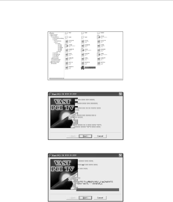
Install TV DRIVER&PROGRAM
1. First, operate TV DRIVER in MASTER CD.
A) select setup
B) select NEXT
C) select NEXT
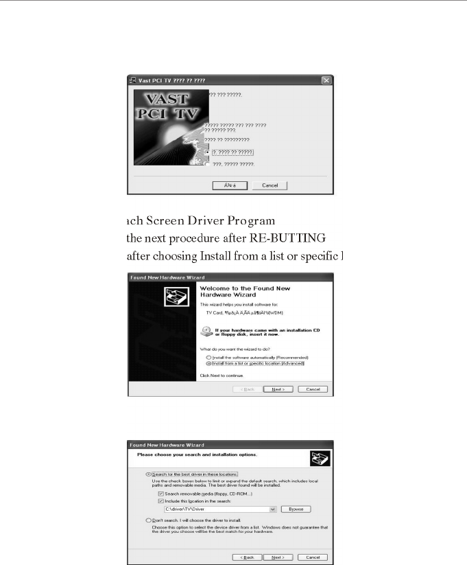
E) proceed to the next procedure after RE-BUTTING
F) select Next after choosing Install from a list or specific location {Advanced}
D) select NEXT
*Install Tach Screen Driver Program
G) Select Next
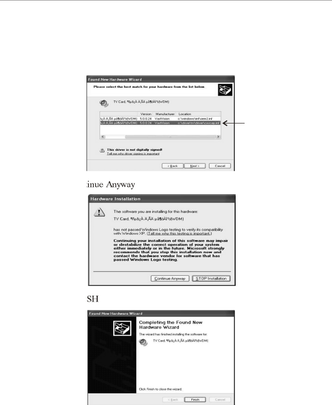
H) According to frequency of TV program installment, driver could happen
several times as shown in the figure.
After selecting the last driver "B", please choose NEXT.
I) Select Continue Anyway
J) select FINISH
B

K) RE-BUTTING after 4 times repetitive operation to figure No.H-J.
L) After confirming whether error exists in device manager of SYSTEM
registration information of my computer as TV driver is finished. select
TV PROGRAM POWER VCR /PVCR3_2001F for automatic
installation.
M) After installing TV Program, install INDEO Program in order.
N) As TV Program installation is finished. refer to chapter Use TV program
for setting.
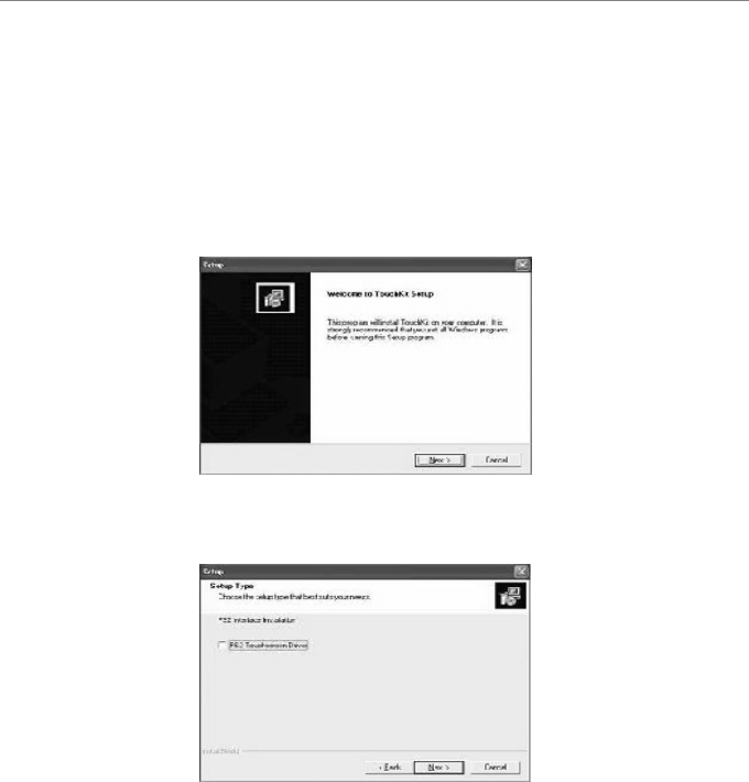
Installing touch screen program and setup
Follow these steps to install TouchKit.
1. Put the TouchKit CD to CD-ROM.
2. Open the "Win2000_XP" directory.
3. Double click the Setup.exe, then windows starts to run the installation
program.
4. Just click [Next>] button to continue installation.
5. Check the check box if PS/2 touch controller is to be installed. The default
setting is unchecked. Then Press [Next>] to continue installation.
6. Choose the setup type that best suits your needs. There are two touchKit
accessory utilities for choosing, "Rotation Monitor Utility" and "Shutdown
Utility". Users can instal the utility they want by checking the box. Then
Press [Next>] to continue installation.
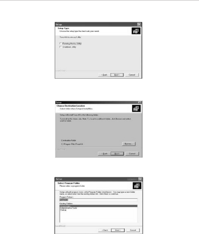
7. Select the appropriate folder where set-up files will be installed. Then press
[Next>] to continue installation.
8. Then type in the name of program folder for TouchKit or press [Next>] to
continue. There will be a default name for it.
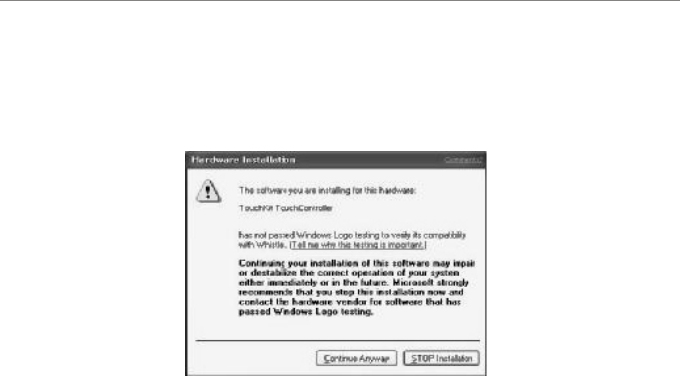
During Installation, the Touchkit controller driver will be installed automatically.
windows XP will prompt a warning message before driver certificated. Now,
Press [continue>] to continue installation.
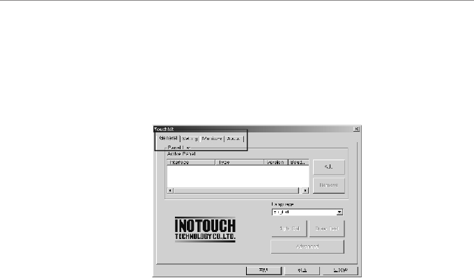
Configuration Utility and Right Button Emulator
There are three property pages in TouchKit utility, and they are General,
Setting and About. Each property page contains different functions for users
to do the adjustments. Therefore, users can easily manage all the TouchKit
controllers through TouchKit Utility.
Functional Group Tap
General
General property page contains the functions of language selection, devices add/
remove, 4 points calibration, Draw test and advanced. Furthermore, there are two
functions int he Advanced, they are 25 points calibration and the support of
multiple monitors.
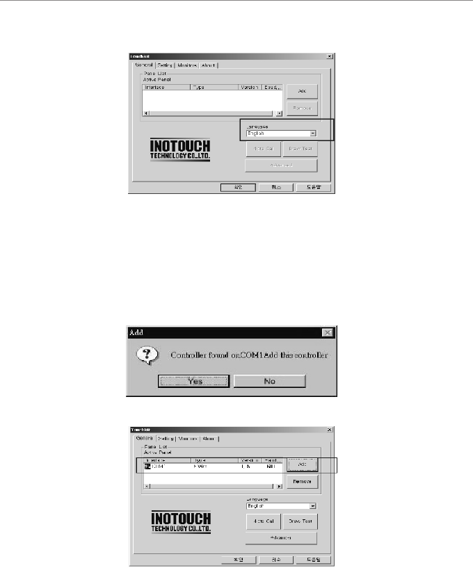
<Language>
TouchKit supports multi-lnguage user interface. User could select native
language that is compatible to operation system support. For example, if the
operation system is a traditional Chinese version, user could see the normal
display words under the traditional Chinese and English mode. There are eight
different languages, English, Traditional Chinese, Simplified Chinese, French,
Spanish, German, Japanese and Korean, supported in this feature of TouchKit.
Note to select the
compatible language first.
Select the compatible language first or user may not see the normal display of
each button.
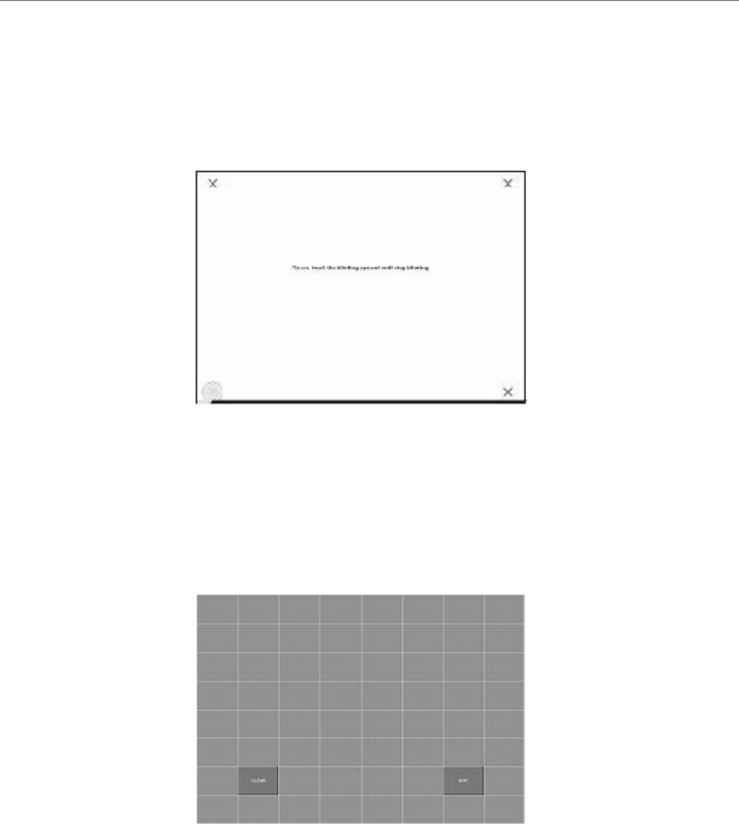
<Add> & <Remove>
Please check the touch panel devices (including its controller) are equipped well,
then click [Add] button to add all of those RS-232 and PS/2 components to the
<Panel List> dialogue box.
There is one devices found. Press [Yes] to continue.
Device is found in COM1
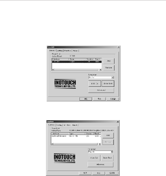
The controller is displayed on the Panel List box. user can get the information of
interface - type - firmware version and baud rate for each controller.
Select one device after import more than one device at the panel list window.
the one selected will activate the panel, and remember to do the calibration
before starting to use touch panel.
There are three buttons, <4pts Cal> <Draw Test> <Advanced>, at the lower
section of the <General> property page.
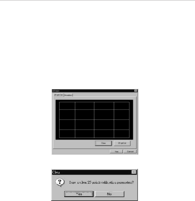
<4pts Cal>
Correct 4 point locations on screen with the panel. Press [4pts Cal], screen
displays as follows.
Touch the blinking symbol on panel until beep or stop blinking.
<Draw Test>
Test the drawing position related to the display screen on panel.
Click on the [Draw Test] button. There will be a squared blue display showing.
In drawing test window, user can click <Clear> button to clear the window. Also,
User can Click <Quit> or press mouse right button to quit from the drawing test.
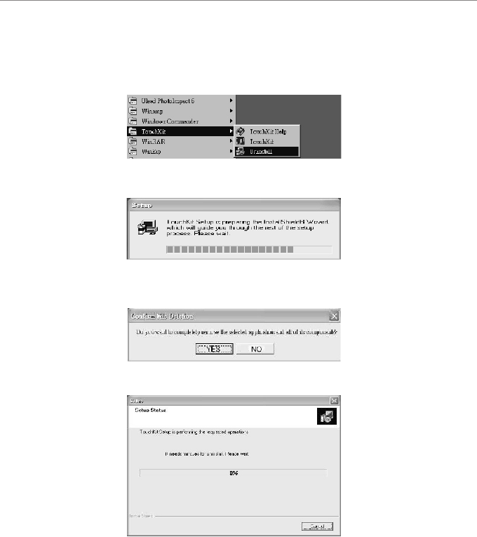
Press [Clear] to clear the previous calibration records.
Press [Yes] to clear previous records.
The record will become default record.
Press [25ptCal] to do 25 points calibration. Correct 25 point locations on screen
with the panel.
If no "touch action" happen within minutes, it will quit from the draw test window
automatically. In drawing test window, user can verify the panel linearity,
calibration capability, and drawing line quality.
<Advanced>
Touchkit provide more accuracy 25 points calibration for touch sensor. In
addition, Touchkit supports multiple monitors configuration in Windows
98/ME/2000/XP. Also, touchkit provide controller setting for capacitive touch
sensor. If the capacitive controller is selected, a capacitive setting property page
appears on the advanced sheet. In general case, it does not need to do 25
points calibration other then bad linearity sensor.
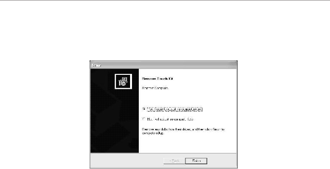
For Windows XP / XP Tablet PC Edition
Follow these steps to uninstall TouchKit.
1. Go to Start / All programs / TouchKit / Uninstall, and execute it.
2. TouchKit setup dialog appears, ad prepares to uninstall.
3. Confirm dialog, press [YES] to start un-installation; [NO] to cancel
un-installation.
4. Start to uninstal TouchKit.
If user does not want to uninstall TouchKit at this moment, press [Cancel]
to terminate the uninstall process.
5. touchKit driver will not be unloaded until system re-boot. Press [Yes>] to
re-boot immediately or [No>] to re-boot later.
Use Windows XP Home Edition
to use application program, like Windows XP Home Edition that Microsoft
provides basically and for basic use of windows XP Home Edition, please
refer
to the manual(brochure) of Microsoft Windows XP Home Edition and
Microsoft Windows XP Home Edition help and support center.
For referring to the help and support center, click your necessary
items on a guide screen appearing by clicking [start]-[help and support]
on Window Wallpaper.
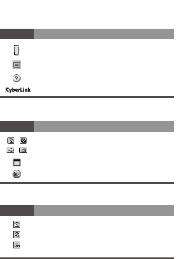
Main Controls
Video Display
Channel Surfing
Icon Description
Turns PowerVCR off
Minimizes PowerVCR
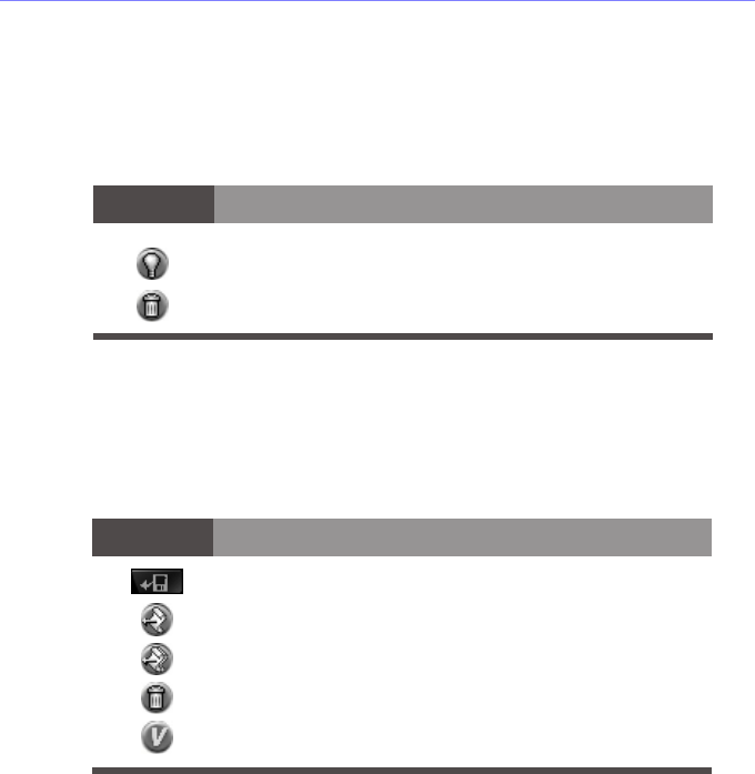
Accesses Online Help
About PowerVCR
Icon Description
Switches between large and small screen mode
Activates the Always On Top function (off/on)
Maximizes video display to full screen
Enters the surfing mode for previewing channels
simultaneously
Icon Description
Cancels surfing mode
Enables auto page mode
Scans channels
TV User's Guide
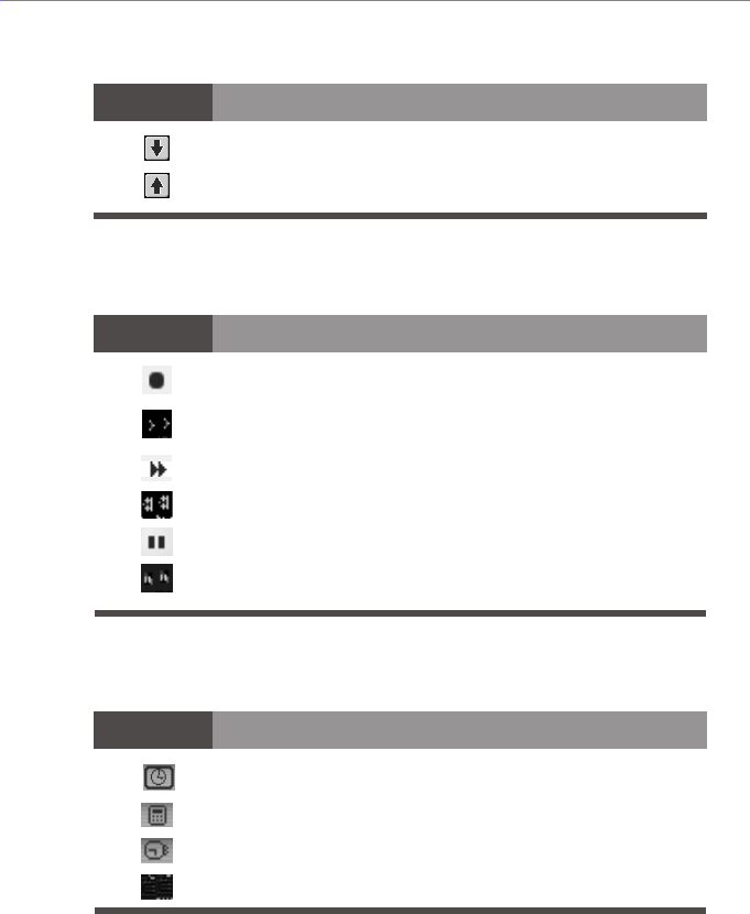
Icon Description
Icon Description
Control Wheel
Display Area
Goes to next page
Returns to previous page
Records video content
Plays video files
Fast forwards video files
Rewinds video files
Pauses video files
Stops video files
Icon Description
Displays replay indicator status
Displays current channel
Displays time remaining until next scheduled task
Displays current file size
Modes
1. Live/Digital Recorder
In this mode, you may watc h live video content and record video content.
TV Tuner Control
Configures PowerVCR's System Settings
Captures still images during playback or from TV
Enables the Time-shifting playback feature
Shows/hides the TV tuner control
Controls playback volume
Goes to next channel
Returns to previous channel
Auto scans for available channels
Returns to the last channel viewed
Icon Description
Icon Description
Displays total time for current file
Displays hard disk space available
Icon Description

2. Instant TV Replay
In this replay mode, you may pause, rewind, play in slow motion, instantly replay
live television, or skip commercials. Video recording is not allowed here. The
default video replay limit is 30 minutes of live video.
Please refer to the "Control Wheel" on page 17 for information on navigating in
the Instant TV Replay mode.
Note: There is no Stop function in the Replay mode.
3. PowerDVD
In this mode, you may enjoy DVD movie titles with the industry's most advanced
DVD software player.
To start PowerDVD, click the PowerDVD mode. PowerVCR will automatically
switch to PowerDVD with only the Master panel remaining. Afterwards, you
may turn off PowerDVD or simply click on Live/Digital Recorder in the Master
panel to return to PowerVCR.
Please refer to the PowerDVD User's Guide for more information on operating
PowerDVD.
4. File Player
In this mode, you may play existing video files. There are two types of files:
MPEG video files and playlist files. Playlist video files contain the description of
the video file(s) and if greater than one, are played in its original playback
sequence.
Opens files for playback
Navigates during playback by advancing or reversing
Steps left during pause or stop mode
Steps right during pause or stop mode
Icon Description
5. Recording Scheduler
In this mode, you may schedule record times and its associated channel. Set the
automatic recording frequency to record serial programs.
Scheduling Wizard that guides you through the scheduling
process
Deletes scheduled tasks
Icon Description
19
Icon Description
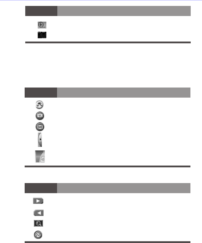
6. File Converter
In this mode, you may convert AVI files to MPEG files according to your
specified recording profile or you may extract DAT files from video CDs to
MPEG-1 files for further editing.
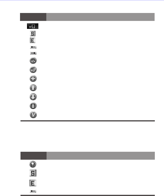
Opens files for converting
Converts selected files
7. Video Trimmer
In this mode, you may choose to cut and splice video clip segments or merge
clips into a new video file.
Converts all files
Deletes conversion tasks
Shows PowerVCR
8. DV Tape Transcoder
In this mode, you may choose to cut and convert DV video clip segments into
new video files.
Step left trim
Step right trim
Edits (trims) selected files
Edits all selected items (merge)
Adds next segment of current tape as a new clip
Goes up to previous task
Goes down to next task
Deletes task
Shows PowerVCR
Adds a new task
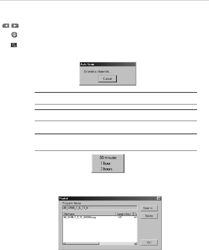
The start trimming position
The end trimming position
Step left trim
Icon Description
The end trimming position
Icon Description
Opens files for editing/trimming
The start trimming position

9. i-Power
In this mode, you may access Internet resources directly from PowerVCR and
also the fantastic CyberEPG service. It provides the latest electronic TV program
guide and links for the PowerVCR Recording Scheduler to automatically
schedule recording tasks.
Please refer to your Internet browser's online help for more information on
surfing the Internet and "i-Power" on page 77.
Step right trim
Transcodes (trims) selected clip
Transcodes all clips
Adds next segment of current tape as a new clip
Marks current tape position as the start trimming position.
Marks current tape position as the end trimming position.
Deletes task
Shows PowerVCR
Icon Description

RECORDING AND PLAYING VIDEO
FILES
After properly setting up your software and hardware peripherals, you are ready
to begin recording and playing video files. Before you begin, you may want to
configure your system settings if the default settings don't suit your need. Refer to
"Chapter 5: Changing System Settings" on page 39 for more information.
Displaying Options
PowerVCR has flexible displaying options located on the video display panel:
Click on the Always on Top icon so that the video display is always visible
and overlaps all desktop application windows
Click on the Resize to enlarge or minimize your video display
Click on Full Screen to enlarge your video display to its maximum
Tips: Double-click on any given area of the video display once to enlarge it to full
screen and once more to restore to window.

Recording
Now you may start recording after everything has been set up properly. If you
would like to configure your system settings before you begin recording or select
another recording profile, please refer to "Chapter 5: Changing System Settings"
on page 39 first.
Channel Surfing
Before recording, you might just want to learn how to surf with PowerVCR. The
incredible surfing function gives you a break from all the channel flipping and
mouse-clicking endured when watching TV by providing a preview of sixteen
channels at a time.
1Be sure that your TV Tuner card (or capture card) is installed correctly or
your PowerVCR screen will be blank.
2Click on Surf Channels located in the video display area.
3Click on Auto Page to allow a continuous refresh of sixteen new channels.
4Click Next and Previous Page to preview other channels.
5Click Auto Scan to scan for available channels.
6Click Cancel Surfing to exit or select one specific channel by clicking on it
to return to the normal display.
Recording with the TV Tuner Control
1Be sure that your TV Tuner card (or capture card) is installed correctly or
your PowerVCR screen will be blank.
2Start PowerVCR. Click the source indicator until the indicator reads TV if
you have an antenna or CATV if you have a cable wire.
Note: PowerVCR will automatically detect and select the country region of your
cable provider and the correct video signal format. If not, please see "Chapter 5:
Changing System Settings" on page 39 for more details.
3
Click the arrow located on the right edge of the PowerVCR panel to activate
the TV Tuner Control.
4Select a desired channel by using the number pad or left and righ t arrows.
5Click on Return to return to the last channel.
6Click Auto Scan to scan all the possible channels. To cancel the scanning,
click Cancel once the Auto Scan dialog box appears and you wi ll be
returned to the original channel.
7After you have selected the desired channel, click Record .
Note: Unlike the playback volume, the recording volume is automatically set and
is not allowed for adjustment in PowerVCR II.
Note: Keep in mind that the TV Tuner Control only works with capture devices
utilizing WDM drivers.
Tips: While recording, click on the recording button to display the Recording
Timer menu. Select one of the time durations and PowerVCR will automatically
stop the recording once the set time duration has expired.
8Click Stop when you are finished.
9The playlist will appear for you to save it.