IEI Integration DS101WIFI 802.11abgn Bluetooth Mini PCIe module User Manual DS101 OM 0815
IEI Integration Corp. 802.11abgn Bluetooth Mini PCIe module DS101 OM 0815
Users Manual
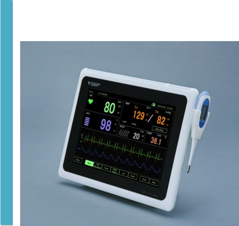
Patient Monitor
DS-101 System
Ver.03
Operation Manual
* Before using the product,
please read this manual thoroughly.
* Store this manual where it can
be always referred to.
Fukuda Denshi Co Ltd.

© 2017 Fukuda Denshi. All rights are reserved. To support the intended use of the product described in this
publication, the purchaser of the products is permitted to copy this publication, for internal distribution only,
from the media provided by Fukuda Denshi. Fukuda Denshi assumes no responsibility for any injury to
anyone, or for any illegal any improper use of the product, which may result from failure to use this product
in accordance with the instructions, cautions, warnings, or statement of intended use published in this
manual.
Fukuda is registered trademark of Fukuda Denshi.
Software in this product is Copyright 2016 Fukuda Denshi or its venders. All rights are reserved. Japan
copyright laws and international treaty provisions applicable protect the software worldwide. Under such
laws, the licensee is entitled to use the copy of the software incorporated with this instruments as intended
in the operation of the product in which it is embedded. The software may not be copied, decompiled,
reverse-engineered, disassembled, or otherwise reduced to human-perceivable form. This is not a sale of
the software or any copy of the software; all right, title, and ownership of the software remain with Fukuda
Denshi or its vendors.
For information about any Fukuda Denshi product, call Fukuda Denshi technical Support:
USA +1 800 365 6668
+1 425 881 7734M
Japan +81 3 3822 2171
United Kingdom +44 1483 728 065
China +86 01 6788 0514
Fukuda Denshi Co. Ltd.
3-39-4 Hongo Bunkyo Tokyo
113-8483 Japan
BriteMED Technology Inc.
3F., NO.306, 306-3, SEC. 1, DATONG RD., SIJHIH DIST., NEW TAIPEI CITY 221, TAIWAN
www.fukuda.com

Page 1
Contents
Contents ......................................................................................................................................................... 1
Introduction ..................................................................................................................................................... 4
Intended Use ............................................................................................................................................... 4
Contraindications ........................................................................................................................................ 4
Symbols .......................................................................................................................................................... 5
Documentation symbols ............................................................................................................................. 5
Power symbols ............................................................................................................................................ 5
Connectivity symbols .................................................................................................................................. 5
Miscellaneous symbols ............................................................................................................................... 5
Screen elements ............................................................................................................................................. 6
About warnings and cautions ......................................................................................................................... 7
General warnings and cautions .................................................................................................................. 7
Controls, indicators, and connectors ............................................................................................................ 13
Setup............................................................................................................................................................. 15
Packing list ................................................................................................................................................ 15
Installation precautions ......................................................................................................................... 18
Mounting the system ............................................................................................................................. 18
Charging the system ............................................................................................................................. 19
DS-101 connection ................................................................................................................................ 20
NIBP relay horse Connection ................................................................................................................ 21
ECG cable connection .......................................................................................................................... 22
SpO2 cable connection ......................................................................................................................... 22
Power up the system ............................................................................................................................. 23
Replacing the battery ............................................................................................................................ 23
Start up ...................................................................................................................................................... 26
Power on screen ................................................................................................................................... 26
Patient login ........................................................................................................................................... 26
Patient registration ................................................................................................................................ 27
Default Setting ....................................................................................................................................... 27
Monitoring ..................................................................................................................................................... 29
Main Screen .............................................................................................................................................. 29
Large screen ............................................................................................................................................. 30
Wave ......................................................................................................................................................... 31
Dual channel mode ............................................................................................................................... 31
ECG cascade mode .............................................................................................................................. 31
ECG mode ............................................................................................................................................. 31
SpO2 mode ........................................................................................................................................... 32
Pause .................................................................................................................................................... 32
Full Disclosure ....................................................................................................................................... 32
Trend ..................................................................................................................................................... 33
Alarm History ......................................................................................................................................... 33
List ......................................................................................................................................................... 33
Event ..................................................................................................................................................... 33
Print ....................................................................................................................................................... 34
Save ...................................................................................................................................................... 34
Page 2
Menu ...................................................................................................................................................... 35
Menu ............................................................................................................................................................. 36
Display Mode ............................................................................................................................................ 36
Patient ................................................................................................................................................... 36
ALARM .................................................................................................................................................. 37
Review ................................................................................................................................................... 37
Parameter Set-up .................................................................................................................................. 42
Set-up .................................................................................................................................................... 44
Power Off ............................................................................................................................................... 48
Alarms ........................................................................................................................................................... 49
Alarm types ............................................................................................................................................... 49
Non-latching alarm .................................................................................................................................... 49
Alarm notification locations ....................................................................................................................... 49
Icons on the Main screen .......................................................................................................................... 50
Reset (pause or turn off) audio alarms ..................................................................................................... 51
Disable the alarm for a period ................................................................................................................... 51
Modify audio pause, alarm pause period .................................................................................................. 52
Adjust vital sign alarm limits ...................................................................................................................... 52
Default alarm limit ..................................................................................................................................... 53
Modify audio alarm notification ................................................................................................................. 53
Alarm Confirmation ................................................................................................................................... 54
On Main screen ......................................................................................................................................... 54
On Review screen ..................................................................................................................................... 54
Alarm message and situation ................................................................................................................... 55
Physiological alarms: Priority High ........................................................................................................ 55
Technical alarms: Priority Low............................................................................................................... 55
Patient monitoring ......................................................................................................................................... 57
ECG .......................................................................................................................................................... 57
ECG frame............................................................................................................................................. 57
ECG display........................................................................................................................................... 57
ECG Electrode Placement .................................................................................................................... 58
ECG Alarm............................................................................................................................................. 58
ECG Monitor Setting (Lead, Sensitivity, Filter, Pacing Detect) ............................................................. 59
RESP (Respiration) ................................................................................................................................... 60
RESP frame ........................................................................................................................................... 60
RESP display ......................................................................................................................................... 61
RESP Alarm ........................................................................................................................................... 61
RESP Setting ......................................................................................................................................... 61
SpO2 ......................................................................................................................................................... 62
SpO2 frame ........................................................................................................................................... 62
Pulse wave display ................................................................................................................................ 63
PR display ............................................................................................................................................. 63
SpO2 and PR Alarm .............................................................................................................................. 63
Measure SpO2 and pulse rate .............................................................................................................. 64
NIBP .......................................................................................................................................................... 65
NIBP frame ............................................................................................................................................ 65
NIBP measure window .......................................................................................................................... 66
NIBP Alarm ............................................................................................................................................ 66
Page 3
Select a cuff ........................................................................................................................................... 67
Cuff measurements ............................................................................................................................... 67
Position the cuff ..................................................................................................................................... 67
NIBP measurement ............................................................................................................................... 68
Take a manual NIBP measurement ...................................................................................................... 69
Interval NIBP measurement and other setting ...................................................................................... 69
Temperature .............................................................................................................................................. 70
Temperature frame ................................................................................................................................ 70
Temperature measurement display ....................................................................................................... 70
Thermometer ......................................................................................................................................... 70
Take a temperature in the Predictive mode .......................................................................................... 70
12 Lead ECG ............................................................................................................................................ 73
12 Lead ECG display ............................................................................................................................ 73
12 Lead ECG Alarm .............................................................................................................................. 73
12 Lead ECG Setting (Sensitivity, Filter, Pacing Detect) ...................................................................... 74
12 Lead ECG Electrode Placement ...................................................................................................... 75
12 Lead ECG Measurement ................................................................................................................. 75
12 Lead ECG Measurement Value ....................................................................................................... 77
Specification ................................................................................................................................................. 78
Specification .............................................................................................................................................. 78
Dimensions ............................................................................................................................................... 81
Standards and compliance ........................................................................................................................... 83
FCC warning ............................................................................................................................................. 83
Safety ........................................................................................................................................................ 83
Performance.............................................................................................................................................. 83
Sound Pressure ..................................................................................................................................... 83
ECG ....................................................................................................................................................... 84
Respiration ............................................................................................................................................ 85
SpO2 (Arterial Oxygen Saturation) ....................................................................................................... 85
NIBP (Non-Invasive Blood Pressure) .................................................................................................... 85
Hazardous Materials Disclosure ................................................................................... 錯誤! 尚未定義書籤。
Electromagnetic Compatibility ...................................................................................................................... 86
Precautions for Safe Operation under Electromagnetic Influence ....................................................... 86
EMC Guidance ...................................................................................................................................... 86
Troubleshooting ............................................................................................................................................ 90
Version History .............................................................................................................................................. 94

Page 4
Introduction
This manual (direction for use) is designed to help you understand the capabilities and
operation of the Fukuda DS-101 series of monitors. The information in this manual, including
the illustrations, is based on a monitor configured with electro-cardiogram (ECG), heart rate,
noninvasive blood pressure (NIBP), body temperature, pulse oximetry (SpO2), and pulse
rate. If your monitor configuration lacks any of these options, some information in this manual
may not apply.
Before using the monitor, read the sections of the manual that pertain to your use of the
monitor.
Intended Use
The DS-101 Patient Monitoring System” is intended for monitoring single adult patient
conditions by measuring/displaying/recording/alarming the patient’s parameters which
include Electrocardiograms (ECG), Heart Rate (HR), Pulse Rate (PR), Respiration (RESP),
Oxygen Saturation of Arterial Blood (SpO2), non-Invasive Blood Pressure (NIBP).
The device is intended to be operated by trained healthcare professionals in hospital
environment, private practices, and during patient transport using battery power.
The device is also used as a data collection terminal with it’s equipped NFC Reader to read
data, such as patient temperature data, from a passive NFC Tag. The NFC Reader
interface does not provide any measurement functions.
The device is not intended to be used in Home, Ambulance, Airplanes, MRI environment,
hyperbaric oxygen chambers, or near flammable anesthetic gasses.
Contraindications
This system is not intended to be used.
l On patients connected to heart/lung machines
l On patients being transported outside a healthcare facility
l Near an MRI machine
l In a hyperbaric chamber
l Near flammable anesthetics
l Near electro-cauterization devices
Page 5
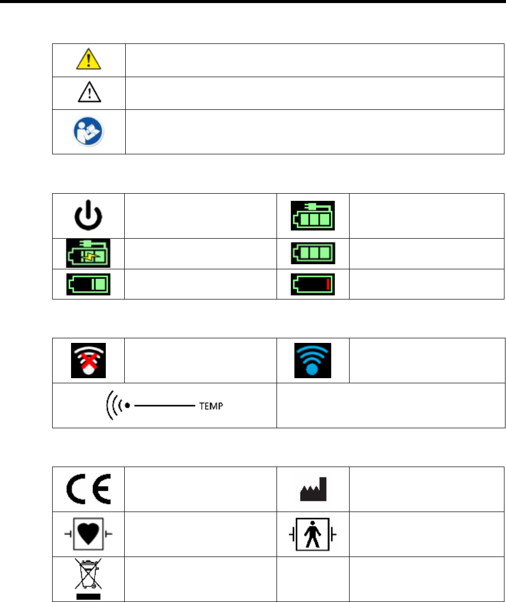
Symbols
Documentation symbols
WARNING The warning statements in this manual identify conditions or
practices that could lead to illness, injury, or death
Caution The caution statements in this manual identify conditions or practices
that could result in damage to the equipment or other property, or loss of data
Read operating instructions
Power symbols
Power on / standby
Monitor is plugged into
Alternating Current power
present, battery fully charged
Alternating Current power
present, battery is charging Battery power operation
Battery level Battery Low / Charge Battery
Connectivity symbols
Wireless LAN is not
connected.
Wireless LAN is connected
Temperature Sensor touch area
Miscellaneous symbols
Meets essential requirements
of European Medical Device
Directive 93/42/EEC
Manufacturer
Defibrillation-proof Type CF
applied parts
Defibrillation-proof Type BF
applied parts
Recycle the products
separate from other
disposables.
Page 6
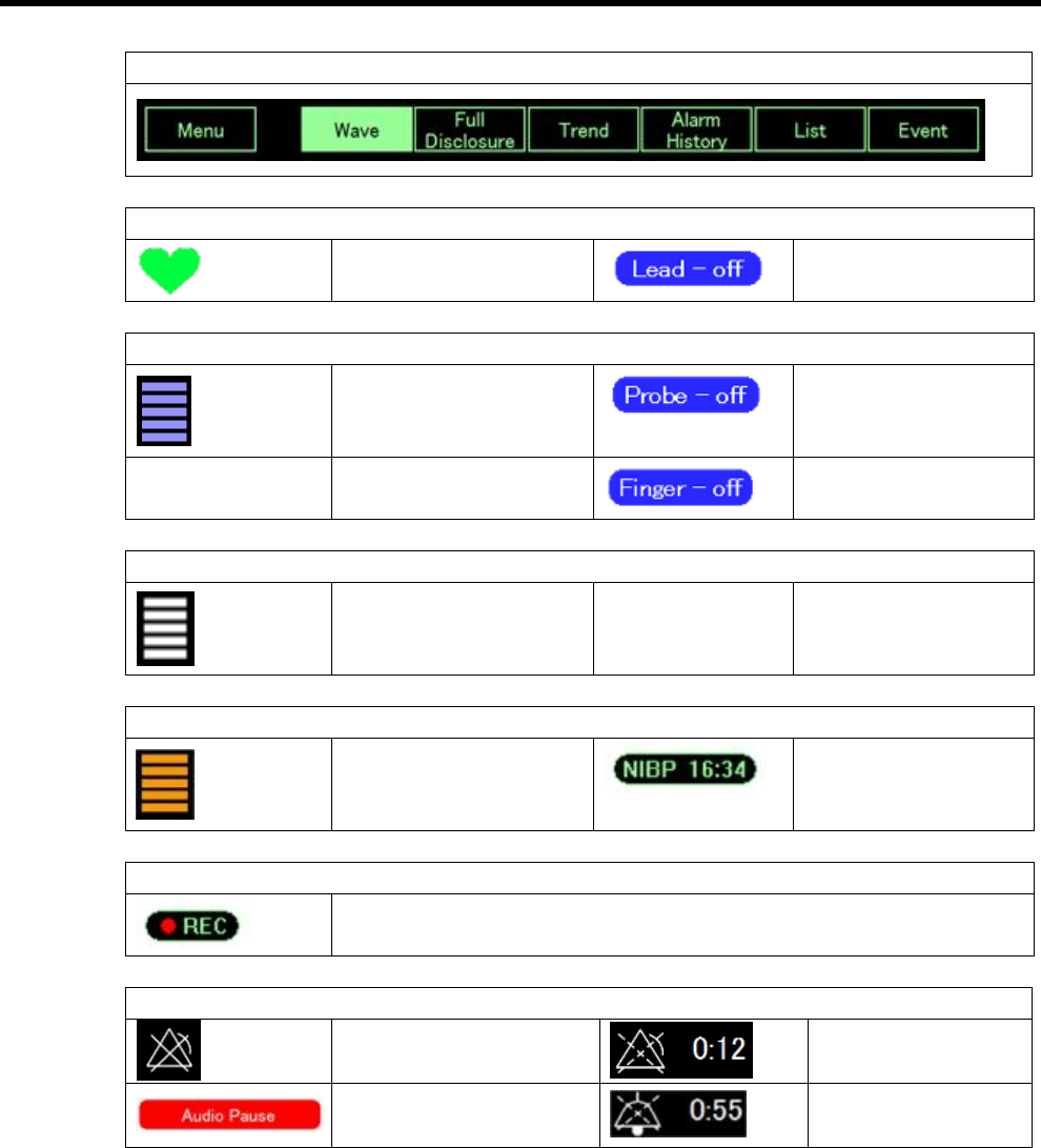
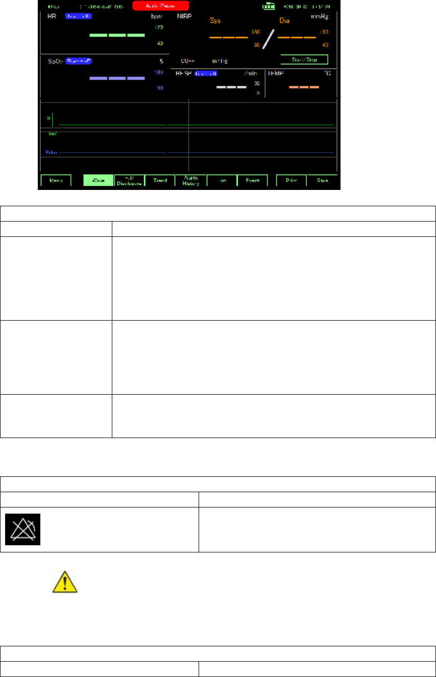
Screen elements
Navigation
HR
Sync Mark
Lead off
SpO2
SpO2 Sync Bar
Probe Off message
Finger Off message
RESP
Resp Sync Bar
NIBP
NIBP Oscillation Bar
NIBP Auto Interval
Timer
Save
Auto Save On
Alarm and information messages
Alarm Off
Alarm Pause &
Count Down Timer
Audio Pause Button Audio Pause &
Count Down Timer
Page 7
About warnings and cautions
Warning and caution statements can appear on the monitor, on the packaging, on the
shipping container, or in this document.
The monitor is safe for patients and clinicians when used in accordance with the instructions
and with the warning and caution statements presented in this manual.
Before using the monitor, familiarize yourself with the sections of this direction for use that
pertains to your use of the monitor.
l Failure to understand and observe any warning statement in this manual could lead to
patient injury, illness, or death.
l Failure to understand and observe any caution statement in this manual could lead to
damage to the equipment or other property, or loss of patient data.
General warnings and cautions
WARNING Many environmental variables, including patient physiology
and clinical application, can affect the accuracy and performance of the
monitor. The clinician must verify all vital signs information before treating
the patient. If there is any question about the accuracy of measurements,
verify the measurement using another clinically accepted method.
WARNING Alarm limits are patient- or facility-specific. The clinician must
set or verify alarm limits appropriate for each patient. Each time the
monitor is powered on, you must check that the alarm settings are
appropriate for your patient before you start monitoring.
WARNING The monitor is not intended for use during patient transport
outside of the medical facility. Do not use the monitor to take
measurements on any patient in transit.
WARNING Use only Fukuda Denshi approved accessories. Using
unapproved accessories with the monitor can affect patient and operator
safety and adversely affect product performance and accuracy. To ensure
patient safety and optimal product performance, use only Fukuda Denshi
recommended accessories and supplies (i.e., cuffs, horses, thermometer,
SpO2 sensors, etc.) and use according to the accessory manufacturer’s
direction for use.
WARNING Inaccurate measurement risk. Do not connect more than one
patient to a monitor.
WARNING Inaccurate measurement risk. Dust and particle ingress can
affect the accuracy of blood pressure measurement. Use the monitor in
clean environments to ensure measurement accuracy. If you notice dust or
lint build-up on the monitor’s vent openings, have the monitor inspected

Page 8
and cleaned by a qualified service technician.
WARNING Liquid can damage electronics inside the monitor. Prevent
liquids from spelling on the monitor.
If liquids are spilled on the monitor:
1. Power down the monitor
2. Disconnect the power plug.
3. Remove battery pack from the monitor.
Note Remove battery pack shall be proceed by trained specialist and
shall not be proceed by user
4. Dry off excess liquid from the monitor.
Note If liquids possibly entered the monitor, remove the monitor from
use until it has been properly dried, inspected, and tested by qualified
service personnel.
5. Reinstall battery pack.
6.
Power on the monitor and verify that the monitor functions normally
before using it.
If liquids enter the USB Box
1. Power down the monitor
2. Disconnect the USB connector.
3. Dry off excess liquid from the USB Box.
Note If liquids possibly entered the USB Box, remove the monitor
from use until it has been properly dried, inspected, and tested by
qualified service personnel.
4. Connect the USB connector
Power on the monitor and verify that the monitor
functions normally
before using it.
WARNING Safety risk. Damaged cords, cables, and accessories can
affect patient and operator safety. Never lift the monitor by the power
supply cord or patient connections. Routinely inspect the AC power cord,
blood pressure cuff, SpO2 cable, and other accessories for strain relief
wear, fraying, or other damage. Replace as necessary.
WARNING Fire and explosion hazard. Do not operate the monitor in the
presence of a flammable anesthetic mixture with air, oxygen, or nitrous
oxide; in oxygen-enriched environments; or in any other potentially
explosive environment.
WARNING The monitor may not function properly if dropped or damaged.
Protect it from severe impact and shock. Do not use the monitor if you
notice any signs of damage. Qualified service personnel must check any
monitor that is dropped or damaged for proper operation before putting the
monitor back into use.
WARNING Defective batteries can damage the monitor. If the battery
shows any sign of damage or cracking, it must be replaced immediately
and only with a battery approved by Fukuda Denshi.
WARNING Electric shock hazard. Do not open the monitor or attempt
repairs. The monitor has no user-serviceable internal parts. Only perform
routine cleaning and maintenance procedures specifically described in this
manual. Inspection and servicing of internal parts shall only be performed
by qualified service personnel.

Page 9
WARNING Inaccurate measurement risk. Do not expose to temperatures
higher than 42.9°C
WARNING Inaccurate measurement risk. Do not use the monitor on
patients who are on heart-lung machines.
WARNING Use the monitor only as described in this directions for use. Do
not use the monitor on patients as described in the Contraindications.
WARNING Inaccurate measurement risk. Do not use the monitor on
patients who are experiencing convulsions or tremors.
WARNING Wall mounted equipment and accessories must be installed in
accordance with accompanying instructions. Fukuda Denshi is not
responsible for the integrity of any installation not performed by authorized
Fukuda Denshi service personnel. Contact an authorized Fukuda Denshi
service representative or other qualified service personnel to ensure
professional installation for safety and reliability of any mounting
accessory.
WARNING Do not place the monitor in any position that might cause it to
fall on the patient.
WARNING Fukuda Denshi is not responsible for the integrity of a facility’s
power. If the integrity of a facility’s power or protective earth conductor is in
doubt, always operate the monitor on battery power alone when it is
attached to a patient.
WARNING Equipment damage and personal injury risk. When
transporting the monitor on a mobile stand, properly secure all patient
cables and cords to keep them clear of the wheels and to minimize trip
hazards.
WARNING For operator and patient safety, peripheral equipment and
accessories that can come in direct patient contact must comply with all
applicable safety, EMC, and regulatory requirements.
WARNING All signal input and output (I/O) connectors are intended for
connection of only devices complying with IEC 60601-1, or other IEC
standards (for example, IEC 60950), as applicable to the monitor.
Connecting additional devices to the monitor may increase chassis or
patient leakage currents. To maintain operator and patient safety, consider
the requirements of IEC 60601-1. Measure the leakage currents to confirm
that no electric shock hazard exists.
WARNING Equipment failure and patient harm risk. Do not cover the air
intake or exhaust vents on the rear and base of the monitor. Covering
these vents could cause overheating of the monitor or muffing of alarms.
WARNING This equipment is not suitable for use in the presence of
electro-surgery.
WARNING Cross-contamination or nosocomial infection risk. Clean and
maintenance the monitor on a routine basis according to your facility’s
protocol and standards or local regulations. Thorough hand-washing
before and after contact with patients greatly reduce the risk of
cross-contamination and nosocomial infection.
WARNING Do not modify this equipment without authorization of the
manufacturer
Page 10
WARNING Conductive parts of electrodes and associated connectors for
type BF or CF applied parts, including the NEUTRAL ELECTRODE,
should not contact any other conductive parts including earth
WARNING The stored data will not be affected. The measurement
accuracy will temporarily decrease during electrosurgery, but it will not
compromise the safety of patient and the equipment.
WARNING To avoid the risk of electric shock, this equipment must only be
connected to a supply mains with protective earth.
WARNING When using SpO2 function under the room temperature of 40
℃, SpO2,SpO2 test finger temperature will up to 43℃
Warning The performance of the AUTOMATED SPHYGMOMANOMETER
can be affected by extremes of temperature, humidity and altitude
Warning Connection to other equipment could result in previously
unidentified risks to patients, operators or third parties. Fukuda Denshi is
not responsible for the integrity of any installation or upgrade not
performed by authorized Fukuda Denshi service personnel. Contact an
authorized Fukuda Denshi service representative or other qualified service
personnel to ensure professional installation for safety and reliability
Warning Changes to other equipment could introduce new risks that
require additional analysis, changes including
- changes in network configuration
- connection of additional items
- disconnection of items
- update of equipment
Warning Devices connect to the system shall fulfill 60601-1 requirement
WARNING Please do not absolutely installation and operation of the
program other than Fukuda Denshi specified in the device. Normal
operation of this equipment cannot be guaranteed.
WARNING Please do not insert USB memory or other equipment while
operating this device. When an application or installation starts
automatically. Normal operation of this device can not be guaranteed
Caution Japan’s Law restricts this monitor to sale, distribution, or use by or
on the order of a physician or licensed healthcare professional.
Caution Electromagnetic interference risk. The monitor complies with
applicable domestic and international standards for electromagnetic
interference. These standards are intended to minimize medical
equipment electromagnetic interference. Although this monitor is not
expected to present problems to other compliant equipment or be affected
by other compliant devices, interference issues still may occur. As a
precaution, avoid using the monitor in close proximity to other equipment.
In the event that equipment interference is observed, relocate the
equipment as necessary or consult manufacturer’s direction for use.
Caution Use only a Class I (grounded) AC power supply cord for powering
this monitor.
Caution Do not use a long press of to power down the monitor when
it is functioning normally. You will lose patient data and configuration

Page 11
settings.
Caution Never move the monitor or mobile stand by pullimg on any of the
cords as this may cause the monitor to tip over or may damage the cord.
Never pull on the power cord when removing it from the power outlet.
When disconnecting the power cord, always grasp the attachment plug
and not the cord. Keep the cord away from liquids, heat, and sharp edges.
Replace the power cord if the strain relief or cord insulation is damaged or
being to separate from the attachment plug.
Caution Use only the Fukuda Denshi USB client cable to connect a USB
Box to the USB port.
Caution If the touchscreen is not responding properly, refer to the
troubleshooting section. If the problem cannot be resolved, discontinue
use of the monitor and contact an authorized Fukuda Denshi service
center or qualified service personnel.
Caution Summation of leakage currents when several items of ME
EQUIPMENT are interconnected
Caution The electrocardiograph incorporates a means to protect the
patient against burns when used with HIGH FREQUENCY(HF)
SURGICAL EQUIPMENT
Caution Cleaning and maintenance procedures
l When cleaning the touch panel, never use strong-acidic cleaning
solution.
l A special coating is applied to the surface of the touch panel. Do not
wipe the surface with a cloth or gauze with coarse texture. Wipe the
surface with an eyeglass cleaning cloth.
l Clean the equipment frequently so stains can be removed easily.
l To prevent injury, it is recommended to wear gloves when cleaning
the equipment.
l Do not allow liquids or cleaning solution to enter the equipment or
connectors.
l Do not use organic solvents, thinner, toluene and benzene to avoid
damaging the resin case.
l Do not polish the housing with abrasive or chemical cleaner.
l When sterilizing the entire room using a spray solution, pay close
attention not to have liquids get into the equipment or connectors,
The surface resin coating may be damaged, resulting in
discoloration, scratches, or other problems.
Example: Do not use chemical cloth, scrub brush, abrasive, polishing
powder, hot water, volatile solvent and chemicals (cleanser, thinner,
benzine, benzol, and synthetic detergent for house and furniture), or
sharp-edged tools.
l Do not open the housing.
l Avoid alcohol or other liquids from getting into the equipment.
l For safe operation of the equipment, regular inspection and
maintenance are required. Once a year, check all cables, devices,
and accessories for damage, earth impedance, earth and leakage
currents, and all alarm functions. Also, ensure that all safety labels
are legible. Maintain a record of these safety inspections.

Page 12
l Regular testing of devices and accessories on a daily basis (by the
clinical OPERATOR) and on a scheduled basis (as a service activity)
is recommended.
Caution Immediate maintenance has to be carried out for the following
case.
l When the equipment was subjected to extreme mechanical stress,
e.g. after a heavy fall.
l When the equipment was subjected to liquid spill.
l When the monitoring function is interrupted or disturbed.
l When parts of the equipment enclosure are cracked, removed, or
lost.
l When any connector or cable shows signs of deterioration.
Caution To prevent intrusion of computer viruses, please use this system
in the closed network except for sending mail
Caution When using this system on a wireless network, please set the
connected device by MAC address on access point and router.
Caution When using this system on a wireless network, please set the
connected device by MAC address on access point and router.
Page 13
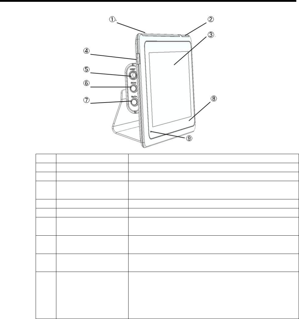
Controls, indicators, and connectors
No.
Feature Description
1 Light bar Provides a visual alarm with red and blue LEDs.
2 Light bar Provides a synchronized heartbeat with green LEDs.
3 LCD screen 1280 x 800 pixels color touchscreen provides a graphical
user interface.
4 Power switch Power-on/Standby switch.
5 NIBP connector Self-contained module for easy replacement.
6 ECG connector Self-contained module for easy replacement. Supports
3lead or 10lead ECG cables.
7 SpO2 connector Self-contained module for easy replacement. Supports
Clip-type or Tape-type SpO2 sensors.
8 NFC touch area Receive body temperature by thermometer into contact
with this place
9 Power Light The LED indicates the charging status
l Green: Power on (Both AC and battery powered)
l Amber: The battery is charged.
l Amber blanking: The battery is charging.
l Black: Power off without AC powered
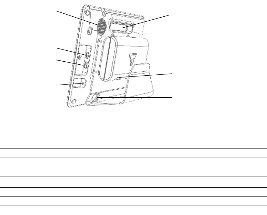
Page 14
No.
Feature Description
1 Speaker Provides an audible Alarm (low or high) and synchronized
heartbeat sound.
2 Handle
3 AUX-1 connector Provides a connection to secure USB-memory for software
upgrades.
4 AUX-2 connector Provides a connection to optional medical devices.
5 IO connector Connect to display module
6 Power connection Provides an external AC power connection.
7 IO connector Connect to Main module.
①
②
③
④
⑥
⑦
⑤
Page 15
Setup
WARNING The labels on the external box are best to be read at a distance
of 30 cm due to the small label size.
To unpack the DS-101, follow the steps below:
1. Use box cutters, a knife or a sharp pair of scissors that seals the box.
2. Open the box.
3. Lift the DS-101 out of the box.
4. Pull the plastic cover off the DS-101.
5. Make sure all the components listed in the packing list are present.
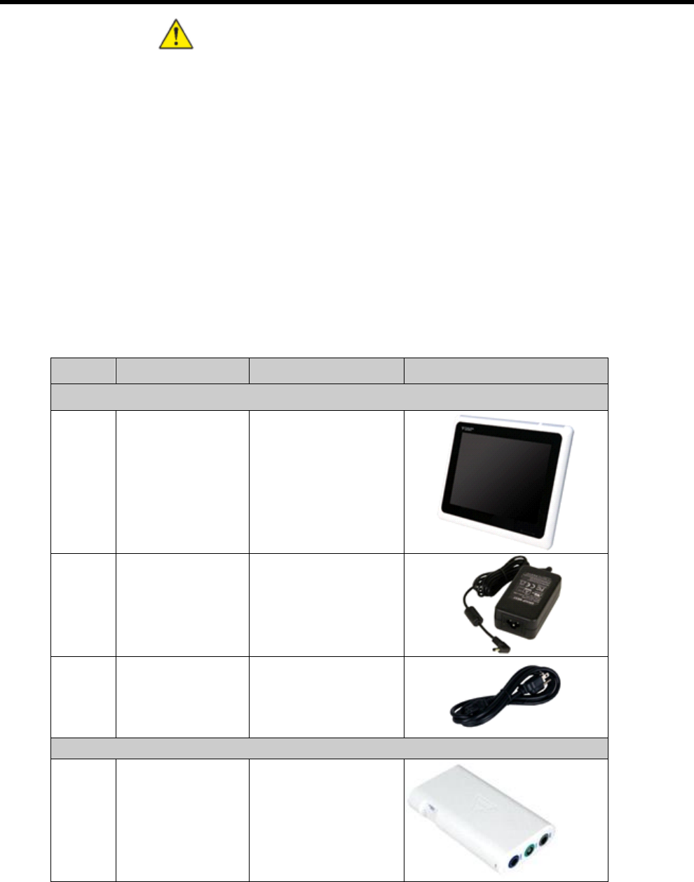
Packing list
The DS-101 is shipped with the following components:
Note If any of these items are missing or damaged, contact the distributor
or sales representative immediately.
Quantity
Description Model Name Image
DS-101
1 Panel PC DS-101
1 AC adaptor 3P ADP-101
1 Power cord
USB-BOX
1 Multiport Data
Collector
HS-101

Page 16
1 USB Cable USB-101
Stand
1 Stand 101STAND
Accessory
1 SpO2 sensor
Reuseable(3m) Clip
type
SPO-10RAC3M
1
ECG CABLE (3
Leads)
CMO-101HR3
1 NIBPcuff for adult M
(23-33 cm)
(30 to 280mmHg)
CUF-101M
1 NIBP relay horse OA-101AP
Page 17
Accessory (Option)
1
SpO2 sensor
Reuseable(3m)
Tape type
SPO-11RAT3M
1
ECG CABLE
12Leads (3m)
CMO-101HR12
1 NIBP cuff for adult L
(31-43 cm)
(30 to 280mmHg)
CUF-101L
1 NIBPcuff for adult S
(17-25 cm)
(30 to 280mmHg)
CUF-101S
1 NFC Thermometer
BT-A71-NFC
Page 18
Hardware installation
Installation precautions
WARNING Failure to take installation precautions during the maintenance
of the device may result in permanent damage to the device and severe
injury to the user.
When installing the DS-101, please follow the precautions listed below:
1. Install and keep the instrument away from splashing water.
2. Protect the instrument from shock and vibration while transporting it.
3. Do not install the instrument where humidity, ventilation, or direct sunlight.
4. Do not install the instrument in a chemical storage area or where gas is generated.
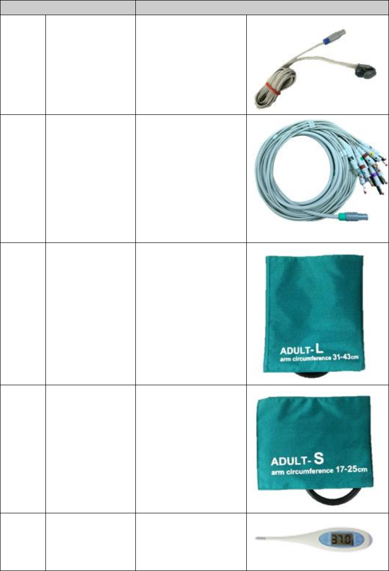
Mounting the system
The DS-101 came with a USB-BOX and a stand. To mount the USB-BOX and the stand, follow the
steps below.
1. Secure the USB-BOX to the stand with four flat-head retention screws.
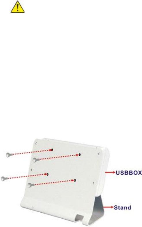
2. Secure the stand to the rear panel of the DS-101 with four retention screws.
Page 19
3. Connect the micro USB cable. Plug the 180-degree connector into the Display connector of
the USB-BOX, and plug the 90-degree connector into the Module connector of the DS-101.
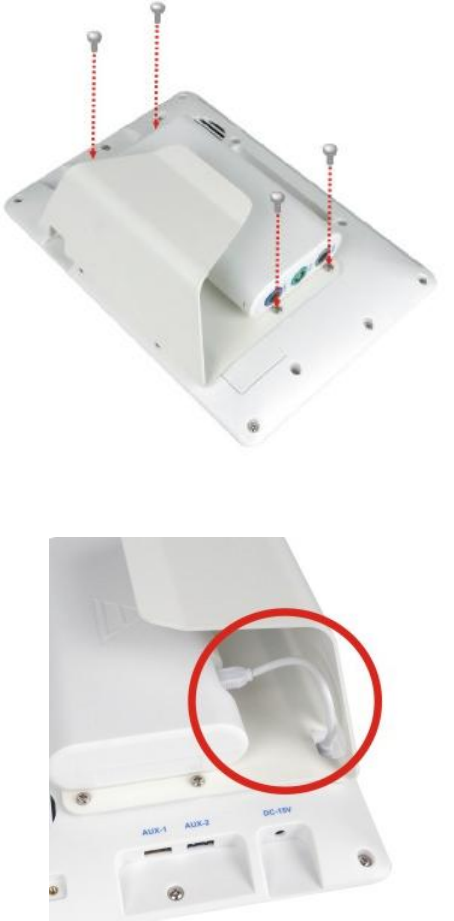
Charging the system
To charge the DS-101, follow the steps below.
1. Connect the DS-101 with a power source through the power adapter came with the package.
2. The system starts to charge the battery and the power status LED lights up in amber indicating
the battery is being charged.
Page 20
3. The user can turn on the system to check the battery capacity on the top right corner of the screen.
Note The battery can only be fully charged when the battery level is lower
than 95% due to battery overcharge protection. In other words, the battery
will not be charged after plugging in the power source when the battery
level is in between 95% and 99%.
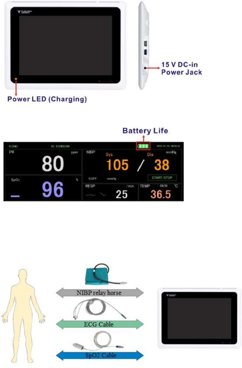
DS-101 connection
Illustrate the connection concept of the DS-101. Please follow the detailed instruction below to connect
the cables for patient monitoring.
Page 21
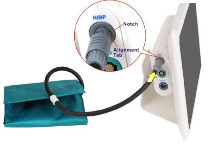
NIBP relay horse Connection
Line up the alignment tab of the NIBP relay horse connector with the notch of the NIBP connector
of the USBBOX. Then, plug in the connector and make sure the connection is secure.
Page 22
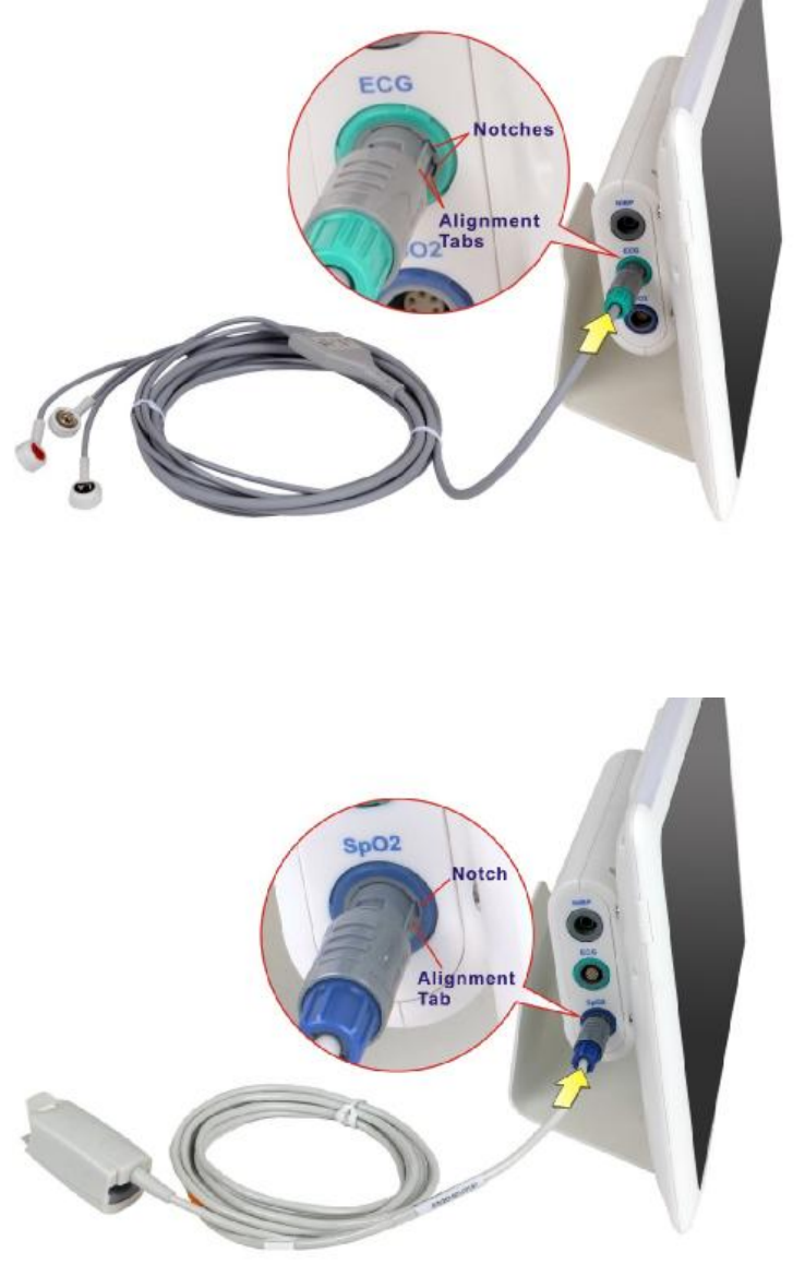
ECG cable connection
Line up the alignment tabs of the ECG cable connector with the notches of the ECG connector of the
USBBOX. Then, plug in the connector and make sure the connection is secure.
SpO2 cable connection
Line up the alignment tab of the SpO2 cable connector with the notch of the SpO2 connector of the
USBBOX. Then, plug in the connector and make sure the connection is secure.
Caution Observe the patient and instrument closely during use. If any
abnormality is observed, immediate proper action, such as stopping the
operation of the instrument, should be taken for the safety of the patient..
Page 23
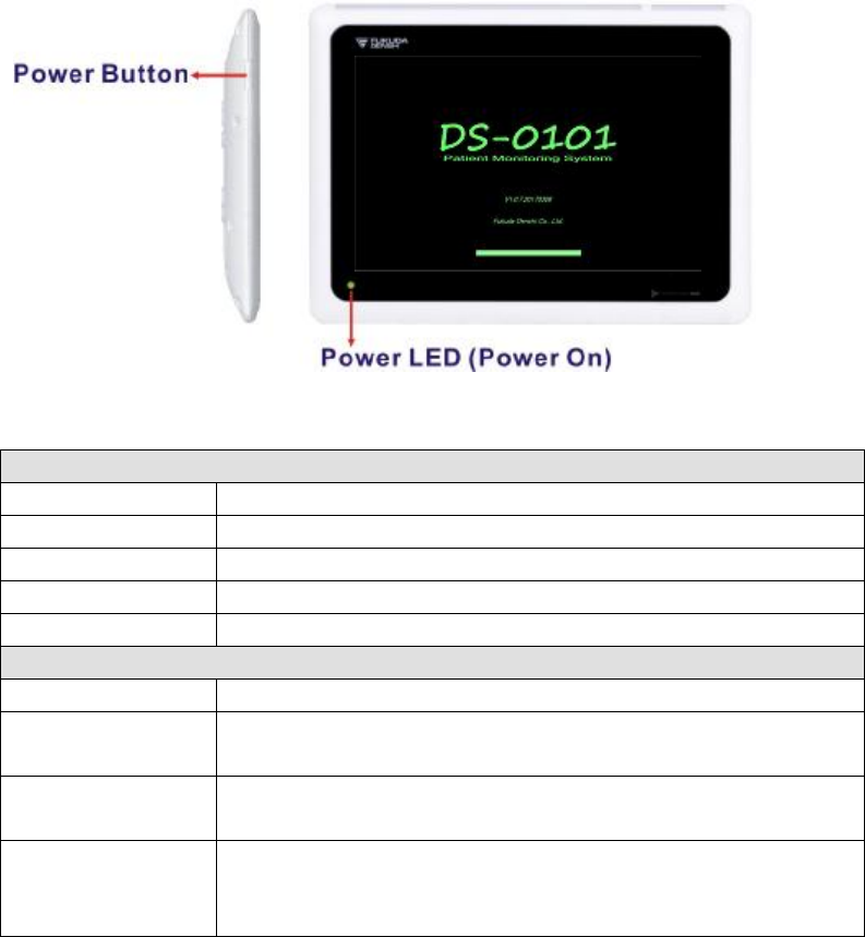
Power up the system
To power-up the system, push the power button on the right side panel for three seconds until the
power status LED on the front panel lights up in green.
The following table lists the power LED status description.
DS-101 Status: Power On or Sleep
Power LED Status
Green Power on
Solid amber The battery is fully charged
Slowly flash in amber The battery is being charged
LED off Power cable disconnected
DS-101 Status: Power Off
Battery Power Status
Lower than 5% The power LED flash rapidly in amber after long-pressing the power button. The
battery power is too low to power up the DS-101.
5% ~ 10% The power LED light up in green after long pressing the power button. The
DS-101 can be powered on to access the software application.
Higher than 10% The power LED light up in green after long pressing the power button. The
DS-101 can be powered on to access the software application. When the power
is lower than 10%, the DS-101 will shut down automatically.
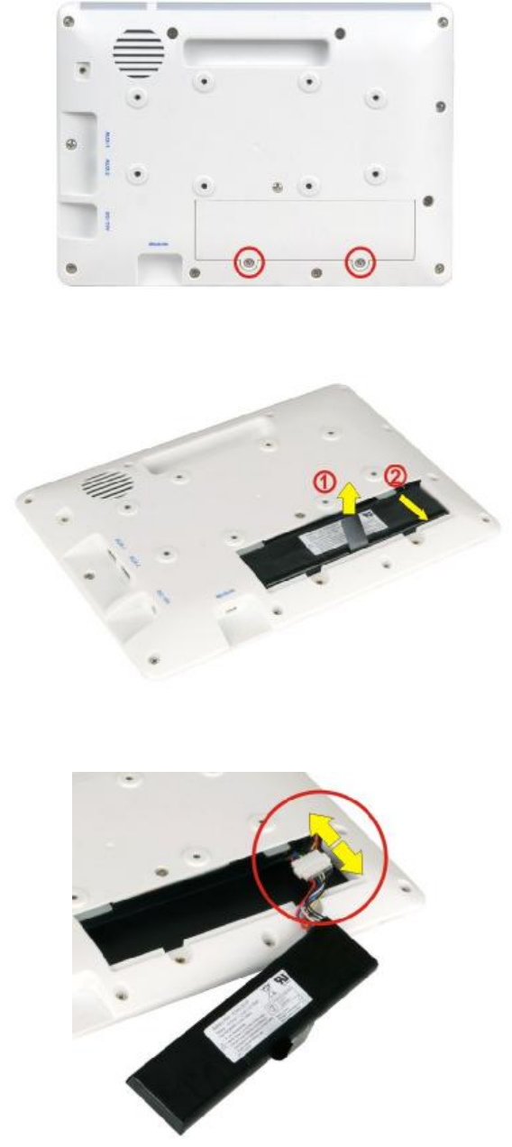
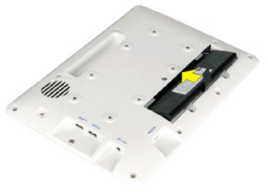
Replacing the battery
This section describes how to replace the battery if necessary.
1. Remove the two retention screws that secure the battery access panel. Then, lift the panel to
remove it.
Page 24
2. Lift the battery pack and pull it out gently until the battery connector shows.
3. Disconnect the battery connector.
4. Connect the battery connector of the new battery pack to the battery connector of the DS-101
by correctly orienting the connector (align keying feature) onto the mating connector.
Page 25
5. Gently organize and insert the connectors and cables back to the original position inside the
DS-101.
6. Slide the new battery pack in at an angle to install it.
7. Secure the battery access panel with the two previously removed retention screws.
Page 26
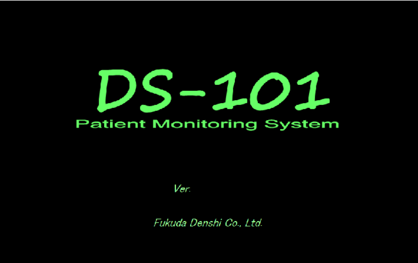
Start up
Power on screen
The following screen appears when the system is turned on.
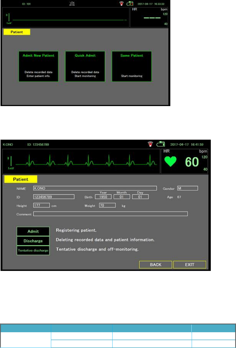
Patient login
The top of the Patient page displays the heart rate (HR) and the waveform detected by the sensor.
The page also contains three option buttons for users to choose:
l Admin New Patient: Delete patient data, and enter the Patient Register page (refer to Section
0).
l Quick Admit: Delete patient data, and enter the Monitor Mode page or the Large Mode page.
l Same Patient: Return to the Monitor Mode page or the Large Mode page to monitor the
current patient.
Page 27
Patient registration
The Patient Registration page shown below allows users to input patient information.
Default Setting
The default setting at the start of monitoring is as follows.
The system setting can set whether to default or continue.
Parameter
Parameter Item Detail Default
ECG Monitor ECG Lead I, II, III II
Sensitivity x0.5, x1, x2, x4 x1

Page 28
Filter Diag., Monitor, Drift Cut Drift Cut
Hum Filter ON, OFF ON
Pacing Detect ON, OFF OFF
ECG 12 leads Sensitivity x0.25, x0.5, x1, x2, x4 x1
Low Cut Filter 0.05Hz, 0.15Hz, 0.3Hz 0.05
High Cut Filter 30Hz, 150Hz, 250Hz, OFF OFF
Hum Filter ON, OFF ON
Pacing Detect ON, OFF OFF
NIBP Pressure Pre-set 120, 150, 180, 200 180
Pressure Limit 150, 200, 250, 300 250
Auto Interval ON, OFF OFF
RESP RESP Lead I, II II
Sensitivity x0.2, x0.5 x1, x2, x4 x1
Patient admit-discharge
Item Default
Birth Year 1970
Month 1
Day 1
Height 0
Weight 0
Alarm Limit
Parameter Unit Lower Limit Upper Limit
HR/PR BPM 40 120
SpO2 % 90 100
Resp /min 5 30
NIBP Sys mmHg 80 180
NIBP Dia mmHg 40 100
Page 29
Monitoring
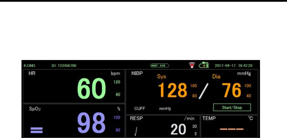
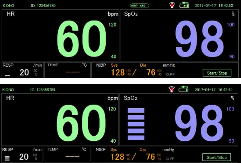
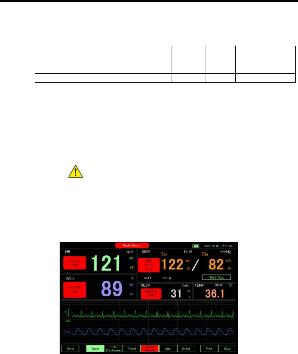
Main Screen
Patient information, battery life, dates and countdown timer are displayed at the top
of the page in the Monitor Mode. The countdown timer in green indicates the
remaining time for next auto blood pressure check. If the number is absent, that
means the auto check function is disabled.
Other displayed values are described below:
l HR: heart rate. A heart icon and a beep will be generated every time the ECG peak
is detected. The numbers under bpm on the right indicate the normal range of heart
rate. If the heart rate exceeds the normal range, the warning sound and icon will be
triggered.
l PR: pulse rate (displayed when SpO2 is selected without ECG channel). A beep will
be generated every time the SpO2 peak is detected.
l SpO2: oxygen saturation
¡ The five blocks on the left show the level of heart beat strength. The three
blocks on the top show the level of the signal strength.
¡ The number beside the percentage sign (%) indicates the normal range. If the
oxygen saturation exceeds the normal range, the warning sound and icon will
be triggered.
l NIBP: blood pressure
¡ The five blocks on the left show the strength level of the blood flow
¡ Time: the time at which the checkup is completed
¡ Sys in orange: Systolic pressure. The small number on the side indicates the
normal range of systolic pressure. If the systolic pressure exceeds the normal
range, the warning sound and icon will be triggered.
¡ Dia in orange: Diastolic pressure. The small number on the side indicates the
normal range of diastolic pressure. If the diastolic pressure exceeds the normal
range, the warning sound and icon will be triggered.
¡ CUFF: the pressure of the cuff
¡ Press START/STOP to start the checkup. After start, press START/STOP
again can stop the checkup.
¡ Press any place other than the START/STOP button to enter the page with
detail information of the NIBP check.
Page 30
l RESP: the number of breaths
l TEMP: press TEMP to enter the page with detail temperature information
Large screen
Patient information, battery life, dates and countdown timer are displayed at the top of the page in the
Monitor Large Mode. The countdown timer in green indicates the remaining time for next auto blood
pressure check. If the number is absent, that means the auto check function is disabled.
Other displayed values are described below:
l HR: heart rate. A heart icon and a beep will be generated every time the ECG peak
is detected. The numbers under bpm on the right indicate the normal range of heart
rate. If the heart rate exceeds the normal range, the warning sound and icon will be
triggered.
l PR: pulse rate (displayed when SpO2 is selected without ECG channel). A beep will
be generated every time the SpO2 peak is detected.
l SpO2: oxygen saturation
¡ The five blocks on the left show the level of heart beat strength. The three
blocks on the top show the level of the signal strength.
¡ The number beside the percentage sign (%) indicates the normal range. If the
oxygen saturation exceeds the normal range, the warning sound and icon will
be triggered.
l RESP: the number of breaths. The block on the left blinks every time a breath is
detected.
l TEMP: press TEMP to enter the page with detail temperature information
l NIBP: blood pressure
¡ The block on the left blinks every time blood flow is detected.
¡ Sys in orange: Systolic pressure. The small number on the side indicates the
normal range of systolic pressure. If the systolic pressure exceeds the normal
Page 31
range, the warning sound and icon will be triggered.
¡ Dia in orange: Diastolic pressure. The small number on the side indicates the
normal range of diastolic pressure. If the diastolic pressure exceeds the normal
range, the warning sound and icon will be triggered.
¡ CUFF: the pressure of the cuff
¡ Press START/STOP to start the checkup. After start, press START/STOP again
can stop the checkup.
¡ Press any place other than the START/STOP button to enter the page with
detail information of the NIBP check.
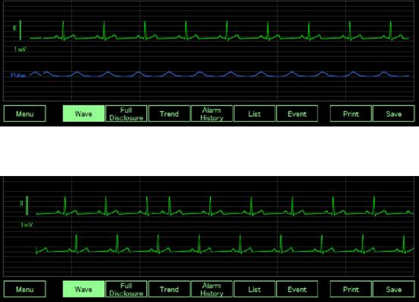
Wave
Dual channel mode
The upper waveform is ECG signal and the lower one is pulse wave.
ECG cascade mode
Display ECG waveform in two areas.
ECG mode
If ECG waveform is displayed in a bigger area, user can change waveform amplitude to see
more detail.
Page 32
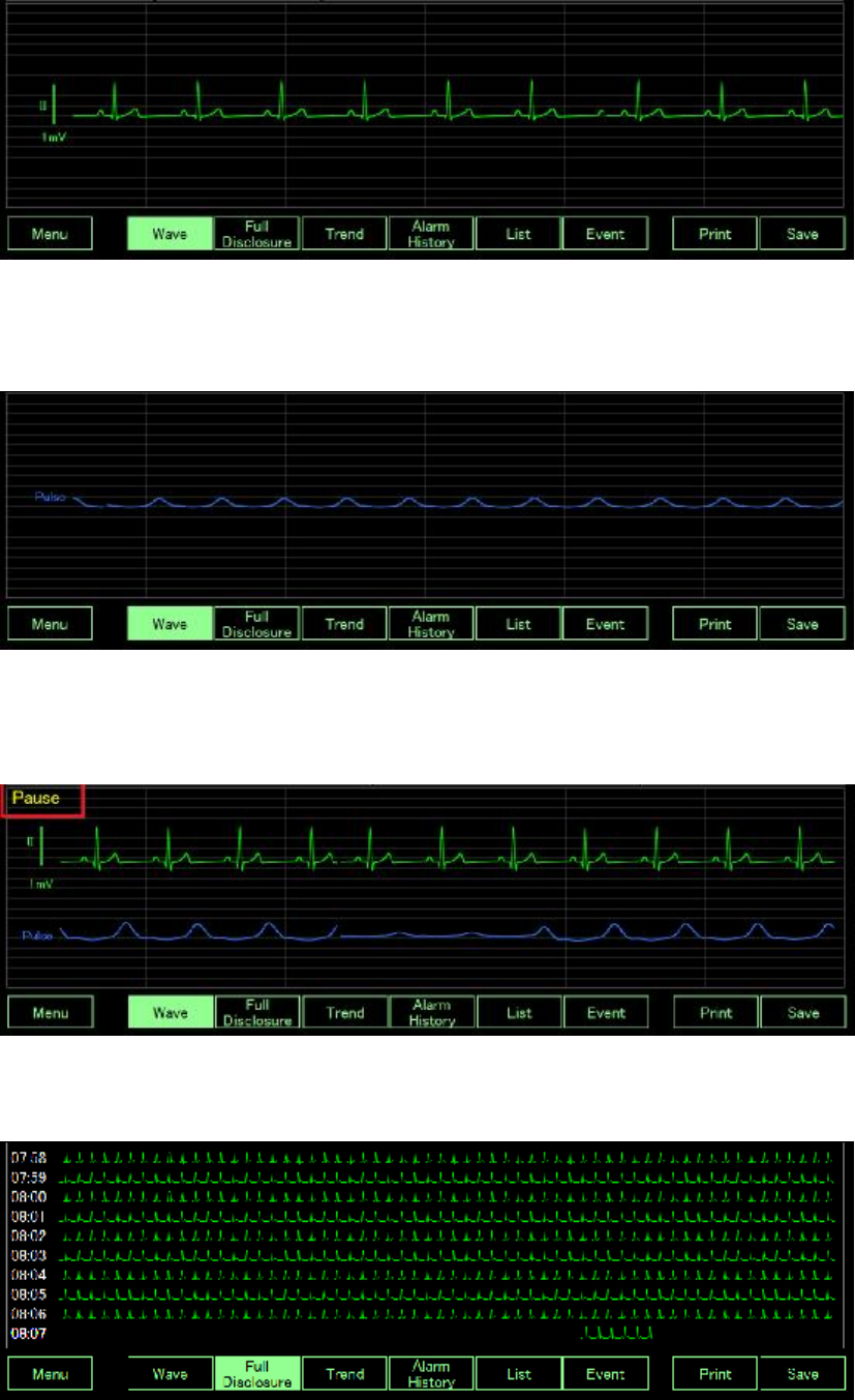
SpO2 mode
If SpO2 waveform is displayed in a bigger area, user can change waveform amplitude to see
more detail.
Pause
If an abnormal waveform is found, the user can click at the waveform display area to stop
waveform update, allowing the user to check the abnormal waveform.
Full Disclosure
User can review previous waveform.
Full disclosure begins halfway corresponding to the time (second) when pressing the Full
Page 33
Disclosure button as shown in the figure. When it comes to the right end, it scrolls and
displays the data for one minute
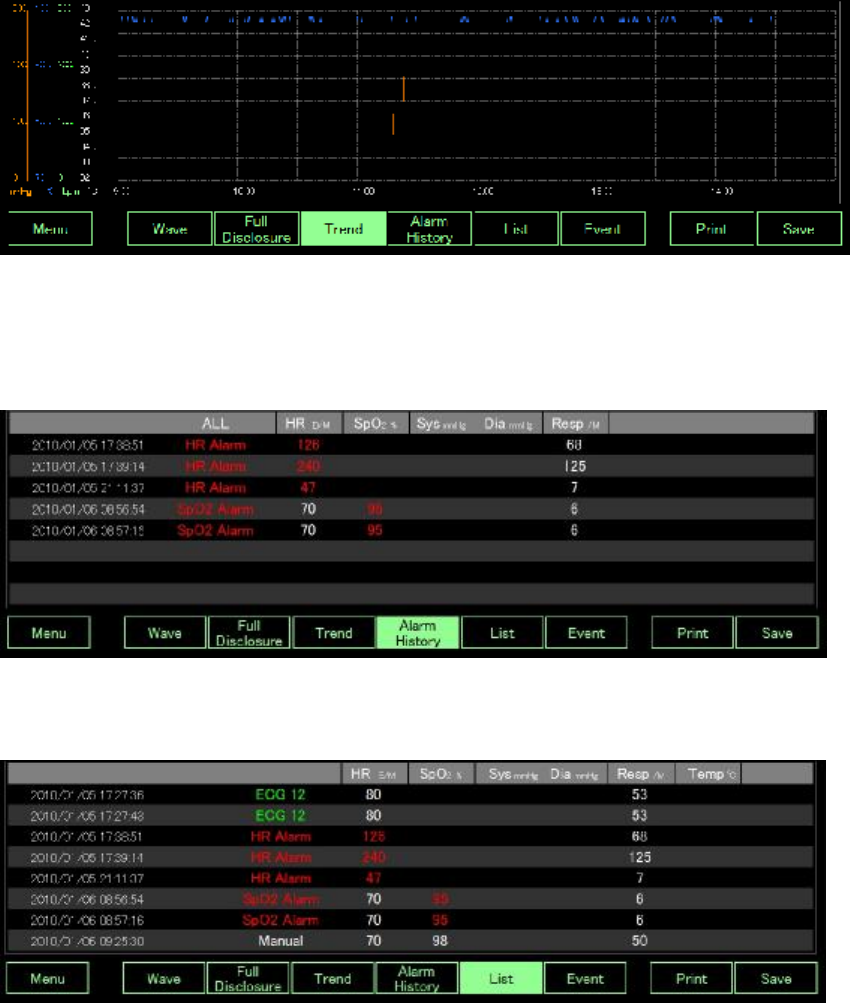
Trend
User can check NIBP, SpO2, heart rate or temperature trend.
Alarm History
User can check the latest alarm history.
List
User can check all latest events in a list.
Event
If there are ECG/SpO2/NIBP/Respiration/Temperature/Manual operations, those events will
be recorded on the timescale.
Page 34
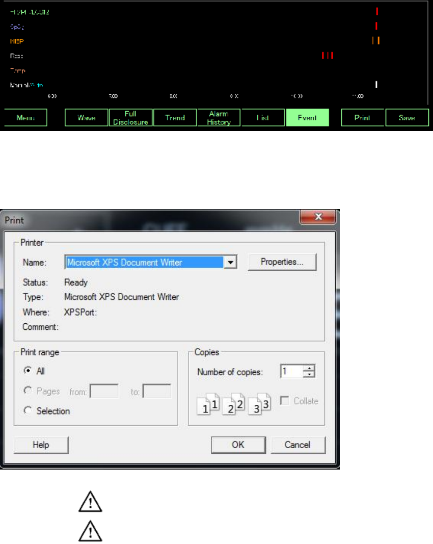
Print
If the user clicks the Print button then the following message box will pop up. The user can
select proper printer to print the waveform.
Caution Print setting need to go to Window Desktop as descript in Power
off section.
Caution Print function is based on Window system, Fukuda Denshi is not
responsible for the integrity of any installation or upgrade not performed by
authorized Fukuda Denshi service personnel. Contact an authorized
Fukuda Denshi service representative or other qualified service personnel
to ensure professional installation for safety and reliability
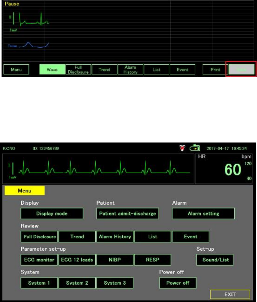
Save
Once the Save button is clicked, the button is disabled and the color is changed to gray. The
system will start storing the image.
Page 35
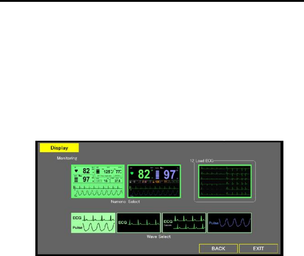
Menu
The Menu page contains several buttons for accessing the setting options of each function.
In dual channel mode, ECG mode and ECG Cascade mode, the upper area of the Menu
page always displays ECG waveform and heart rate number. In SpO2 mode, the upper area
always displays SpO2 waveform and pulse rate number.
Click EXIT to go back to the Main Screen.
Page 36
Menu
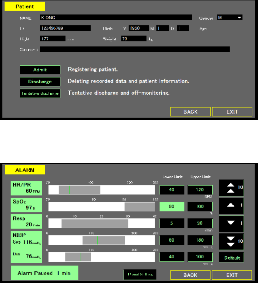
Display Mode
The Display page allows users to select monitor mode and waveform display mode. The
options include:
l Mode Select:
¡ Main Screen
¡ Large Screen
¡ 12 Lead ECG
l Monitor Wave:
¡ Dual Channel
¡ ECG
¡ ECG Cascade
¡ SpO2
l BACK: go to Menu page.
l EXIT: exit the Menu page and go back to the Main Screen.
Patient
The Patient page allows users to input patient information, delete patient record or tentative
discharge.
Page 37
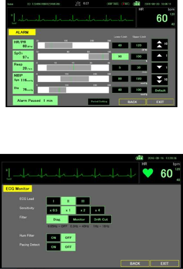
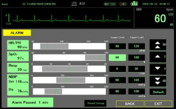
ALARM
Click each icon to enable or disable alarm function. User can set a normal range. If the
measured value is not in the normal range then the alarm will be triggered.
Review
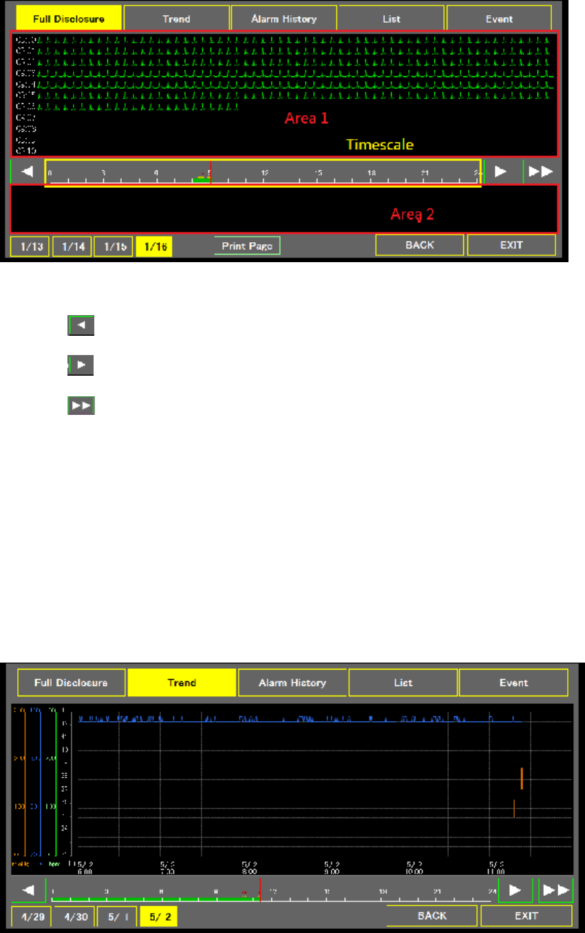
Full Disclosure
Users can check ECG shrinking waveform in the upper area (Area 1). If the user wants to
see certain part of ECG, please click on Area 1 to have the ECG waveform display original
ECG waveform in Area 2.
Page 38
The Full Disclosure page also contains the following buttons:
l : go back 10 minutes.
l : go forward 10 minutes.
l : jump to the end.
l Timescale :
¡ Green bar: there are ECG waveforms in the database.
¡ Yellow dots: there are events at that time
¡ Red dots: there are alarms triggered at that time
l 1/13, 1/14, 1/15, 1/16: change Timescale range.
l Print Page: print full disclosure waveform.
l BACK: go to Menu page
l EXIT: go to Main Screen.
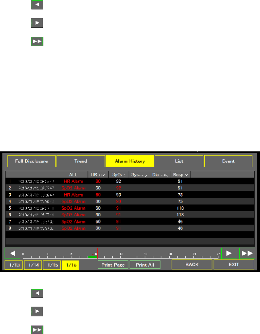
Trend
The Trend page displays ECG, SpO2, temperature trend and the time of NIBP
measurement.
Page 39
The Trend page also contains the following buttons:
l : go back 6 hours.
l : go forward 6 hours.
l : jump to the end.
l Timescale :
¡ Green bar: there are ECG waveforms in the database.
¡ Yellow dots: there are events at that time
¡ Red dots: there are alarms triggered at that time
l 1/13, 1/14, 1/15, 1/16: change Timescale range.
l BACK: go to Menu page
l EXIT: go to Main Screen.
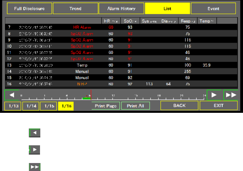
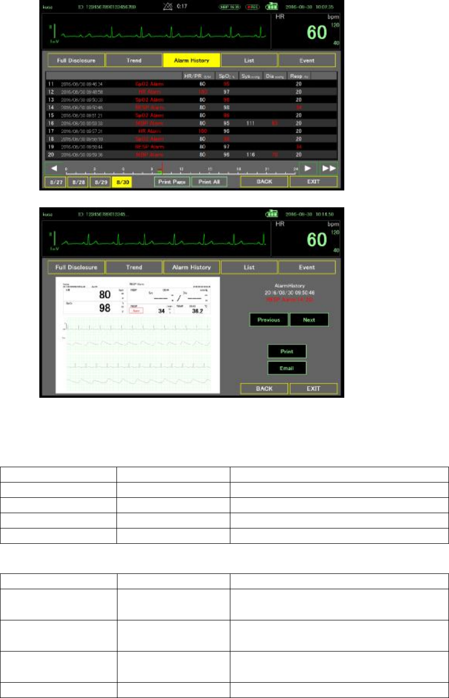
Alarm History
The Alarm History page displays heart rate, SpO2, NIBP, respiration alarm time and related
data. If you double click the alarm column, it will lead to the Review page.
The Alarm History page also contains the following buttons:
l : jump to previous 10 items.
l : jump to next 10 items.
l : jump to the end.
l Timescale :
l Green bar: there are ECG waveforms in the database.
l Yellow dots: there are events at that time
l Red dots: there are alarms triggered at that time
l 1/13, 1/14, 1/15, 1/16: change Timescale range.
l Print Page: print current list.
l Print All : print all alarm list (the maximum number is 100)
l BACK: go to Menu page
Page 40
l EXIT: go to Main Screen.
List
The List page displays all alarm, manual operation, time and related data. If you double click
alarm column, it will lead to the Review page.
The List page also contains the following buttons:
l : jump to previous 10 items.
l : jump to next 10 items.
l : jump to the end.
l Timescale :
¡ Green bar: there are ECG waveforms in the database.
¡ Yellow dots: there are events at that time
¡ Red dots: there are alarms triggered at that time
l 1/13, 1/14, 1/15, 1/16: change Timescale range.
l Print Page: print current list.
l Print All : print all alarm list (the maximum number is 400)
l BACK: go to Menu page
l EXIT: go to Main Screen.
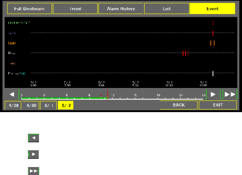
Event
The Event page shows marks of ECG, SpO2, NIBP, RESP, temperature and Manual
operation events.
Page 41
The Event page also contains the following buttons:
l : go back 1 hour.
l : go forward 1 hour.
l : jump to the end.
l Timescale :
¡ Green bar: there are ECG waveforms in the database.
¡ Yellow dots: there are events at that time
¡ Red dots: there are alarms triggered at that time
l 1/13, 1/14, 1/15, 1/16: change Timescale range.
l BACK: go to Menu page
l EXIT: go to Main Screen.
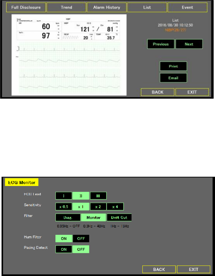
Review
The Review page will be shown when the user double clicks an item from the list of the Alarm
History page or the List page. The texts on the right side indicate the occurred time and the
name of the selected item. Take the following figure as an example: HR Alarm of List means
the information shown on the left is the content of the HR alarm in the List page, the 7th item
of 16 items from the list.
Page 42
The Review page also contains the following buttons:
l Previous: previous stored image.
l Next: next stored image.
l Print: print image
l Email: email to someone.
l BACK: go to Alarm History page or List page.
Parameter Set-up
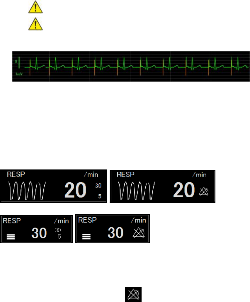
ECG monitor
The ECG Main Screen contains the following setting options and buttons:
l ECG Lead: select Lead source.
l Sensitive: adjust ECG amplitude
l Filter: select filter
l Hum Filter: disable or enable hum filter
l Pacing Detect: disable or enable pacing detect
l BACK: go to Menu page.
l EXIT: go to Main Screen.
ECG 12 Leads
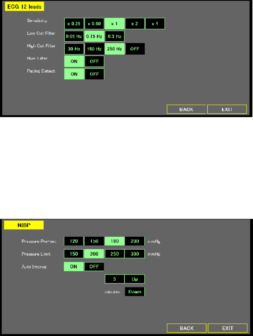
Page 43
The ECG 12 Leads page contains the following setting options and buttons:
l Sensitive: adjust ECG amplitude
l Low Cut Filter: select frequency
l High Cut Filter: select frequency
l Hum Filter: disable or enable hum filter
l Pacing Detect: disable or enable pacing detect
l Rhythm Lead: select ECG source
l BACK: go to Menu page.
l EXIT: go to Main Screen.
NIBP
The NIBP page contains the following setting options and buttons:
l Pressure Pre-Set & Pressure Limit: setting the air pump range.
l Auto Interval:
¡ OFF: Disable
¡ ON: Enable auto measurement function. User can control Up & Down to adjust
interval. A countdown timer will be displayed on the top of the Main Screen.
l BACK: go to Menu page.
l EXIT: go to Main Screen.
RESP
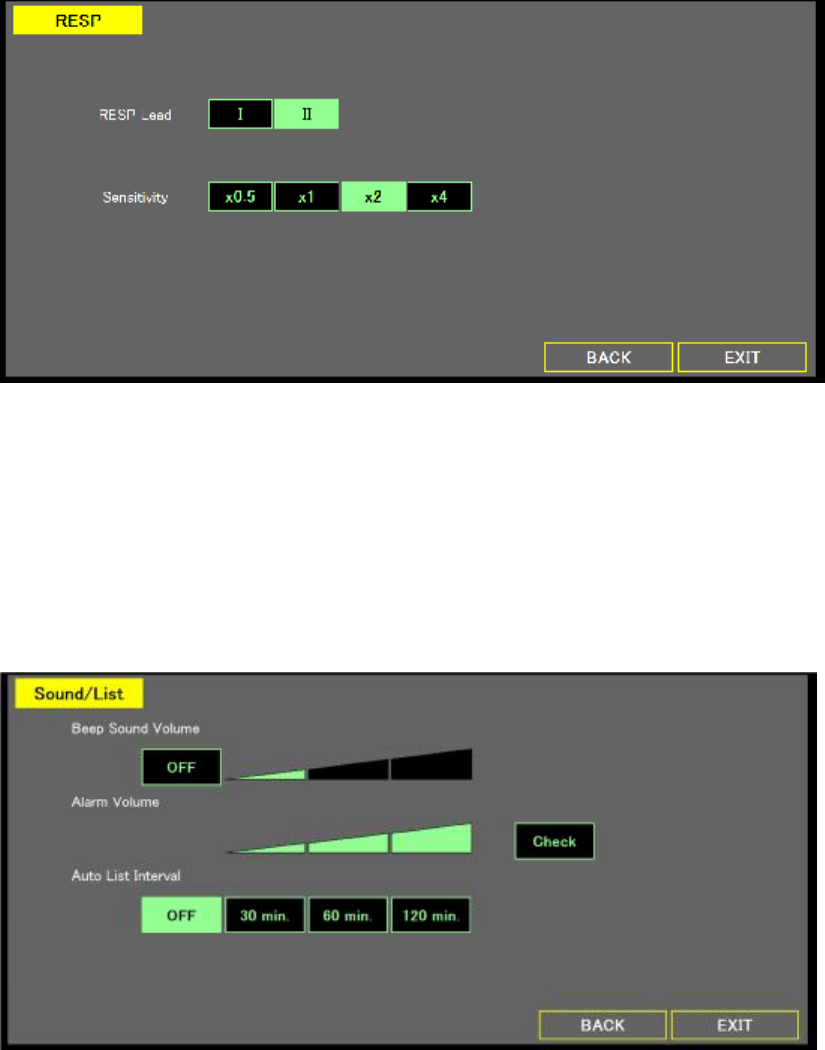
Page 44
The RESP page contains the following setting options and buttons:
l RESP Lead: select respiration lead
l Sensitivity: adjust waveform amplitude.
l BACK: go to Menu page.
l EXIT: go to Main Screen.
Set-up
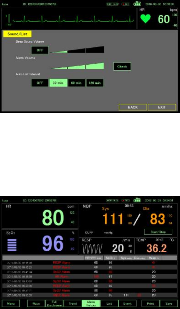
Sound/List
The Sound/List page contains the following setting options and buttons:
l Beep Sound Volume: adjust beep sound volume.
l Alarm Volume: adjust alarm volume.
l Auto List Interval: depend on interval setting to store Monitor image.
l System Mode: select different parameter setting.
l BACK: go to Menu page.
l EXIT: go to Main Screen.
System
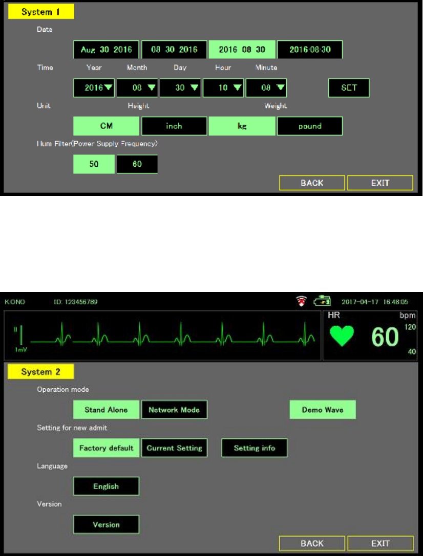
Page 45
The System 1 page contains the following setting options and buttons:
l Date: select date format
l Time: set system time
l Unit: change height and weight unit.
l Language: select language
l Hum Filter: select filter frequency.
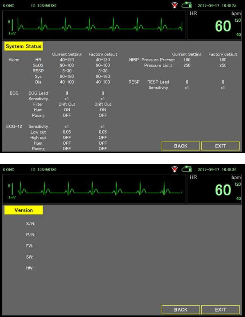
The System 2 page contains the following setting options and buttons:
l Operation mode: Use as “Stand Alone” or “Network Mode”, currently these two mode
has no difference. For demonstration purpose adding “Demo Wave” mode
l Setting for new admit: For adding new user, using “Factory default” setting or “Current
Setting” for new user, able to click “Setting info” has a summary page for all the settings
as below picture
l Language: Select proper language for use, currently support English only
l Version: Click Version button to have the related information including hardware and
software as below picture
Page 46
Page 47
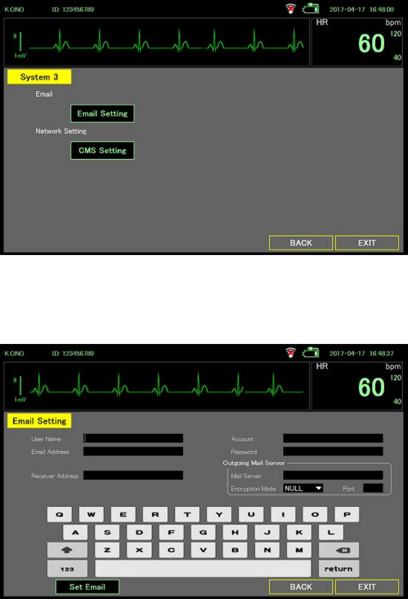
The System 3 page contains the following setting options and buttons:
l E-mail Setting: Set the email related information for sending mail function, image as
below.
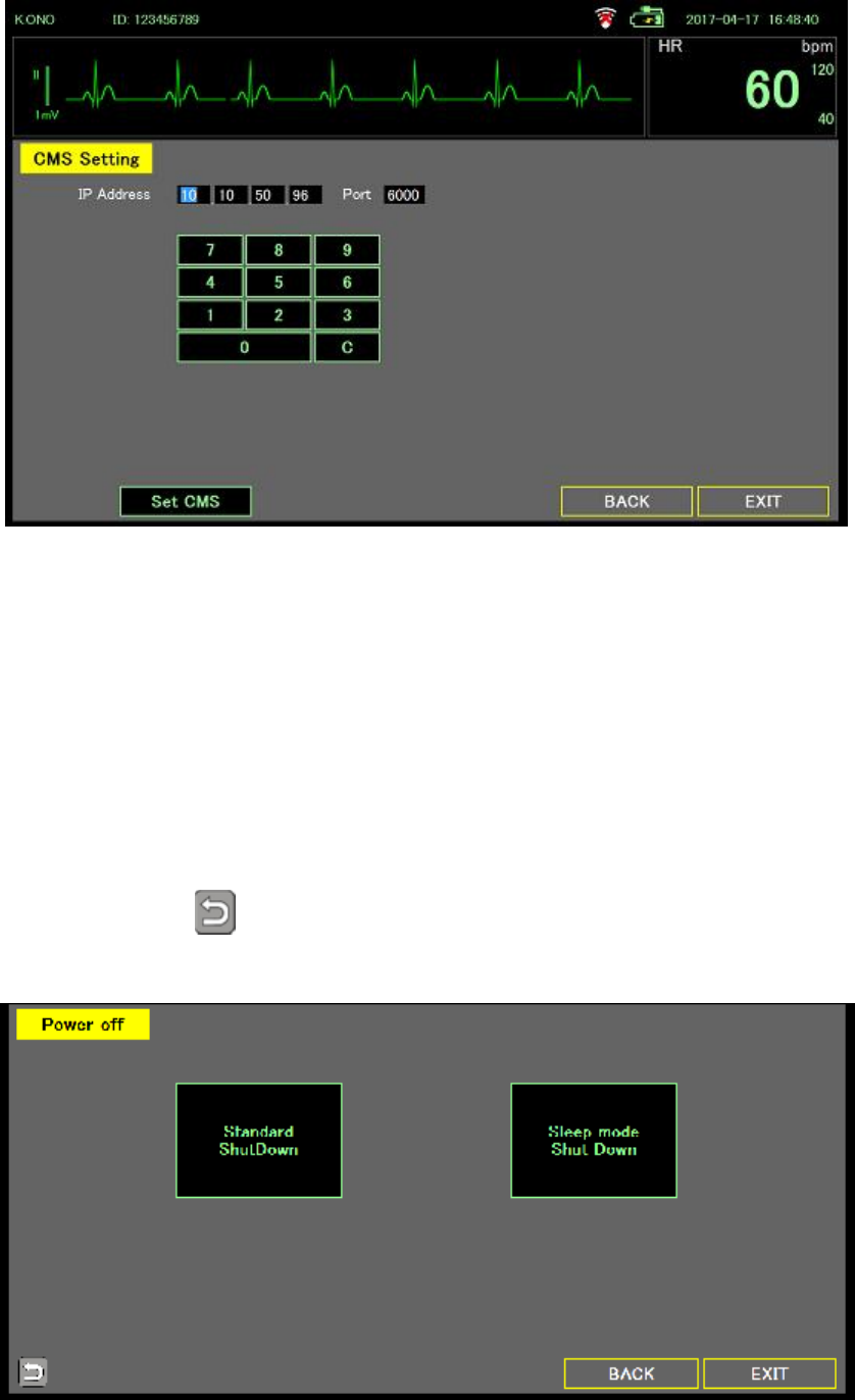
l CMS Setting: Setting up CMS IP information, current version software does not enable
this function.
Page 48
Power Off
The Power Off page provides the following three options for users to power off the system or
to close the application:
l Standard Shutdown
Press “Standard ShutDown” button.
DS-101 turns off
l Sleep Mode
Press “Sleep mode Shut Down” button.
DS-101 enters sleep mode. Press the power button to start up quickly.
l Exit Software
Press button.
Entering the password and return key, ends DS-101 and returns to Windows.
Page 49
Alarms
The monitor presents physiological alarms and technical alarms. Physiological alarms occur
when vital sign measurements fall outside of set alarm limits.
Alarm types
Type Priority Color Alarm audio tone
Heart Rate, Respiration rate, SpO2, NIBP, or
Pulse rate limit exceeded
High Red 5-pulse tone
Some technical alarms Low Blue 1-pulse tone
Non-latching alarm
The alarm of this monitor is non-latch type.
The alarm stops when the vital sign returns within the set alarm limits.
However, alarms that occurred in the past can be confirmed in the alarm history screen.
If there is an unconfirmed alarm, change the Alarm History button to red and inform it
Alarm notification locations
WARNING If you are relying on visual alarm notifications, maintain a clear
line of sight with the monitor. If you are relying on audio alarm notifications,
ensure that you can hear audio alarms from where you are. Set the
volume as needed considering the environment and ambient noise levels.
LED light bar
The light bar on the top of the monitor illuminates as follows:
l Flashing red for high priority alarms
l Constant blue for low priority alarms
Main screen
Page 50
Main screen notifications
Notification Description
Information area Audio pause button appears when alarm occurs. If the audio
pause button is pressed, a timer countdown appears.
If monitoring is started within 1 minute (or 2 minutes), or alarm
pause button is pressed, alarm does not work. During that time
countdown timer is displayed. (Depending on the setting in 1 or 2
minutes)
Parameter area Display alarm information with red (high priority) or blue (low
priority) frame.
If multiple alarms are active, the most recent alarm message
appears.
You can confirmation each alarm on the alarm history screen.
Menu area Alarm History button changes color to red. By pressing this button
you can confirmation alarm on the alarm history screen, and the
button changes color to black.
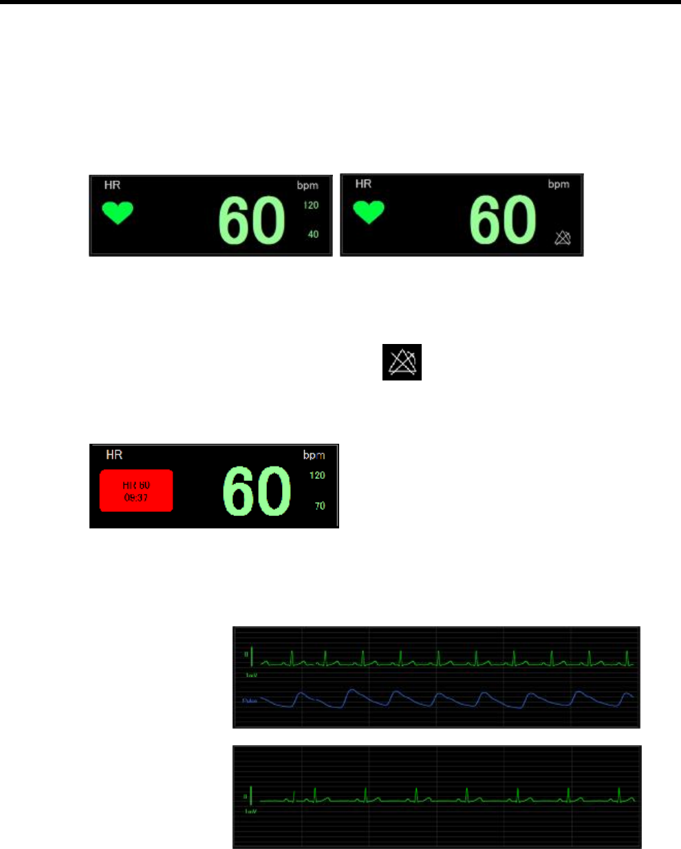
Icons on the Main screen
Icons in the parameter area
Icon Name and status
Alarm off.
No visual or audio alarms occur for this limit.
WARNING Alarm does not work during 12-lead ECG measurement. Also,
the countdown timer of Alarm Pause is displayed from the start of
monitoring and returning to monitoring from the 12-lead ECG
measurement during which the alarm will not operate
Icons in the information area
Icon Name and status
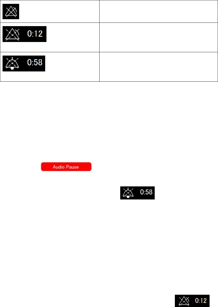
Page 51
Alarm off.
No visual and audio alarms occur.
Alarm paused.
Audio and visual notifications are paused for a
period ranging from 1 to 2 minutes. This icon
remains until the pause time counts down to 0.
Audio paused.
The audio tone is paused for a period ranging
from 1 to 2 minutes. This icon remains until the
pause time counts down to 0.
Reset (pause or turn off) audio alarms
1. Alarm occur
l Audio and visual alarm occur when vital sign measurements fall outside of set
alarm limits
l Flashing red LED and 5-pulse tone sound.
l Alarm message frame appears on parameter area.
l Sound Pause button appears on information area.
2. Audio paused
l Touch button.
l Audio alarm stops but flashing LED continues.
l Audio pause count down timer appears.
l Investigate the cause of the alarm and deal with it
l Change the alarm limits if necessary
l Alarm messages will not disappear unless Vital signs returns within alarm limits
Disable the alarm for a period
You can disable the alarm for a certain period of time
1. Go to the Alarm setting screen.
l Touch the Menu button on Main screen.
l Touch the Alarm setting button on Menu screen.
2. Disable the alarm for a period.
l Touch the Alarm Paused key
If the alarm is off, the icon on the Main screen in the parameter area.
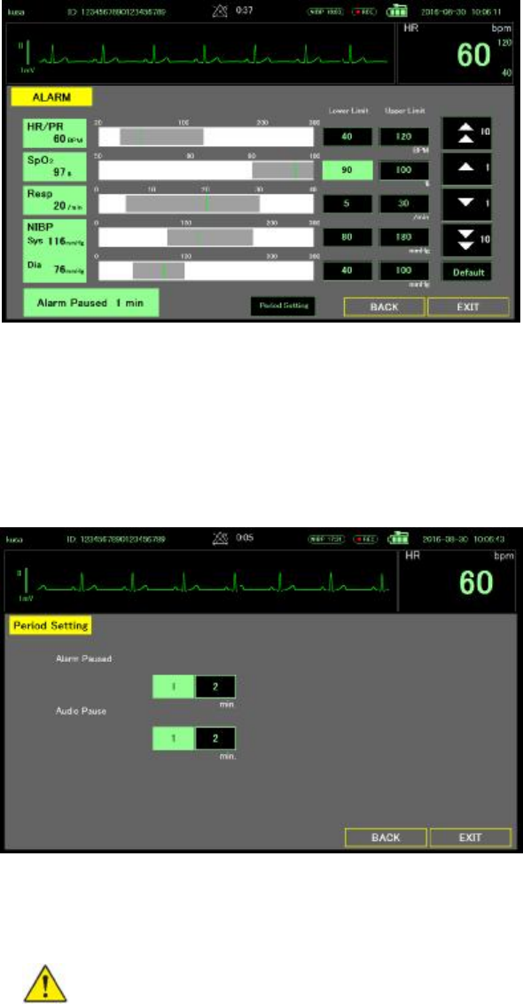
Page 52
Modify audio pause, alarm pause period
You can modify the period of audio alarm pause
1. Touch the Menu key.
2. Touch the Alarm setting key.
3. Touch the Period setting key
4. On the Period setting screen, modify period.
Adjust vital sign alarm limits
You can adjust vital sign alarm limits or turn off alarm limit checking for individual parameters.
WARNING Alarm limits are user adjustable. All alarm limit settings should
be set accordingly for each patient.
1. Go to the Alarm setting screen.
l Touch the Menu button on Main screen.
l Touch the Alarm setting button on Menu screen.
2. Adjust vital sign alarm limits.
l To adjust a limit: Enter the desired upper and lower alarm limits using the up/down
arrow key by touch the Lower/Upper limit button.
l To turn alarm off: Touch the parameter button for which you want to turn off the
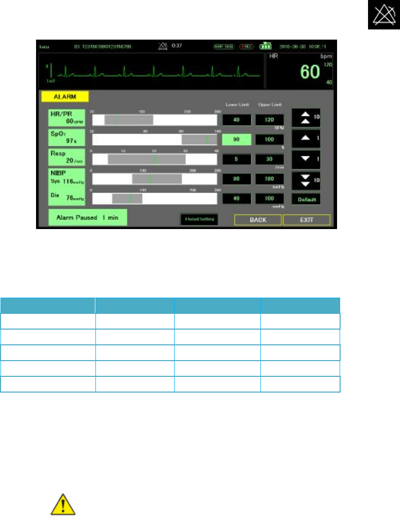
Page 53
alarm.
If you turn off alarm, no visual or audio alarm signals will occur for those parameters.
If the alarm is off, the icon on the Main screen in the parameter area.
Default alarm limit
You can set the alarm limit to default with touch the “Default” button.
Default alarm limits are follows.
Parameter Unit Lower Limit Upper Limit
HR/PR BPM 40 120
SpO2 % 90 100
Resp /min 5 30
NIBP Sys mmHg 80 180
NIBP Dia mmHg 40 100
NOTE Whether the alarm limit at patient admit to the default value or to use the previous
patient value depends on System setting
Modify audio alarm notification
You can modify the volume of all audio alarm.
WARNING The alarm volume should be loud enough for you to hear it
from where you are. Set the volume considering the environment and
ambient noise level.
l Touch the Menu key.
l Touch the Sound/List key.
l On the Sound/List screen, modify alarm volume level.
Page 54
Note You can check the alarm sound volume by pressing the Check key.
Alarm Confirmation
You can check past alarms.
On Main screen
1. Touch the Alarm History key.
2. You can check up to 8 alarms in the past.
On Review screen
1. Touch the Menu key.
2. Touch the Alarm History in the Review category.
3. You can check up to 200 alarms with the arrow keys
Page 55
4. Double-click on the alarm time to check the waveform at that time.
Alarm message and situation
Physiological alarms: Priority High
Alarm messages Display area Situation
HR XX hh:mm ECG frame Heart Rate alarm limit exceeded at hh:mm
RESP XX hh:mm REP frame Resp rate alarm limit exceeded at hh:mm
SpO2 XX hh:mm SpO2 frame SpO2 alarm limit exceeded at hh:mm
NIBP XX/YY hh:mm NIBP frame NIBP alarm limit exceeded at hh:mm
Technical alarms: Priority Low
Alarm messages Display area Situation
Lead-off ECG frame ECG lead is not connect or 1 or more
electrodes out of the body
Lead-off 12L ECG screen ECG lead disconnect or 1 or more
electrodes out of the body
Lead-off RESP frame ECG lead disconnect or 1 or more
electrodes are out of the body
Probe-off SpO2 frame SpO2 sensor is not connect

Page 56
Finger-off SpO2 frame SpO2 sensor is out of finger
Page 57
Patient monitoring
ECG
ECG frame
From the ECG frame, you can measure Heart Rate (HR).
Located in the upper right corner of the Main screen, the ECG frame contains data and
features relevant to ECG. (Main Screen and Larged Screen)
l You can check the Heart Rate
l You can see the synchronized heart beat with blinking heart mark.
l You can see Heart Rate alarm limits. (Upper and Lower), right of the Heart Rate.
l If alarm is off, you can see alarm off mark.
l When either of If HR goes out of the alarm range, the red LED flashes, an alarm tone
sounds and an alarm message is displayed.
ECG display
The ECG waveform is always display on the bottom of the Main screen, expect of SpO2 only
modes.
ECG & SpO2 mode
ECG mode
Page 58
ECG cascade mode
l ECG lead is displayed on the left side of the screen.
l Calibration bar linked to the ECG sensitivity is displayed on the left side of the screen.
l Touch the screen to fix the waveform.
WARNING If the system shows “LEAD OFF”, please refer to the trouble
shooting section
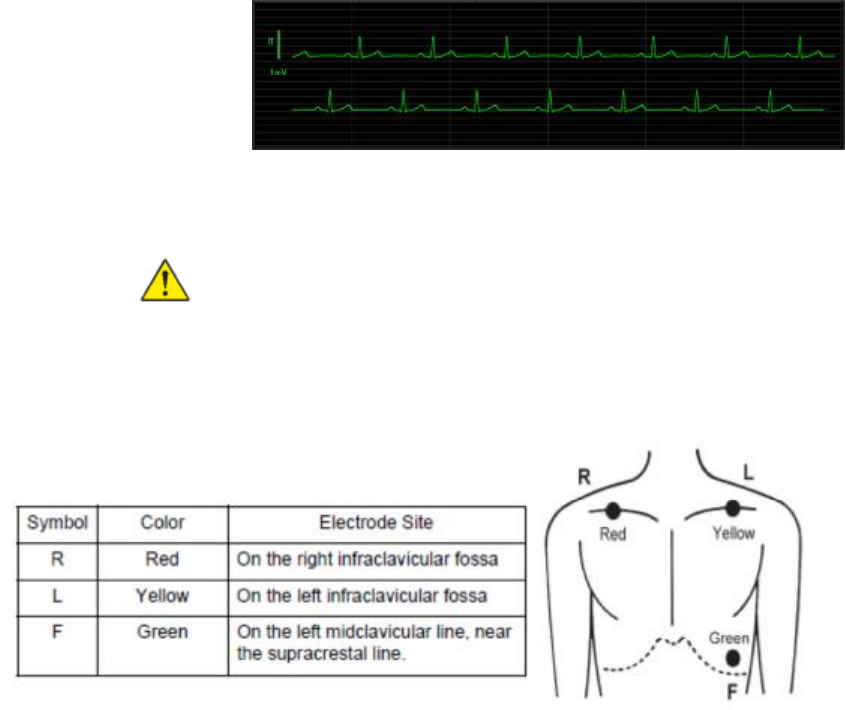
ECG Electrode Placement
Please place electrode as below graph
ECG Alarm
1. Touch the Menu key.
2. Touch the Alarm Setting key.
3. Heart Rate is displayed in the HR/PR key and the green line on the bar graph
4. To set the Hart Rate alarm limits, use the arrow key on the right side of the screen to
follow these steps:
l Touch the Lower Limit key, change limit using arrow key.
l Touch the Upper Limit key, change limit using allow key.
l Alarm limit is changed immediately.
5. If you want to turn off the alarm, press the HR/PR key to make it black.
Page 59
ECG Monitor Setting (Lead, Sensitivity, Filter, Pacing Detect)
1. Touch the Menu key.
2. Touch the ECG Monitor key.
3. You can configure the lead, sensitivity, filter, and pacing detect.
4. Select ECG Lead.
l The ECG function can use 3 wire and 10 wire lead.
l Only I, II, III leads can be selected regardless of which lead is used.
l Choose the lead with the QRS of ECG, the largest on the monitor.
5. Select Sensitivity
The height of the vertical ruler that appears to the left of the ECG waveform indicates 1
mV amplitude and is 10 mm high if x1 is chosen.
6. Select the Filter in accordance with the intended use.
l Diag.: Use when observing the ST change due to ischemia.
l Monitor: Usually, use this mode.
l Drift Cut: Select when using in an environment with a lot of ac noise. Waveform
distortion increases.
Note This DS-101 does not have arrhythmia detection. Please
carefully observe the patient's condition by using upper / lower limit
alarm of Heart Rate.
Page 60
Note Detection of ischemia is the interpretation of the clinician only,
the DS-101 does not provide automated ischemia detection.
Note It is normal for the ECG baseline to wander slightly in Diag. Filter.
7. Turn on the Hum Filter with the intended use.
Turn on when AC noises enter even if electrode and lead wires are adjusted.
8. Turn on the Pacing Detect with the intended use.
l Used for pacemaker patients.
l Pacing Detection is on, the DS-101 displays pacemaker signals exactly as they are
captured.
WARNING PACEMAKER PATIENTS. See this manual for disclosure of
the pacemaker pulse rejection capability of this instrument”
WARNING Heart Rate may continue to count the pacemaker rate during
occurrences of cardiac arrest or some arrhythmias. Do not rely entirely
upon rate meter alarms. Keep pacemaker patients under close
surveillance
RESP (Respiration)
RESP frame
From the RESP frame, you can measure Respiration Rate (RR).
Located in the center of the Main screen, the RESP frame contains data and features
relevant to Respiration.
Main Screen
Large Screen
l You can check the Respiration Rate
l You can see the synchronized chest motion with RESP wave (Main Screen) or 5 level
bar (Large Screen).
l You can see Respiration Rate alarm limits. (Upper and Lower), right of the RR.
l If alarm is off, you can see alarm off mark.
l When either of If RR goes out of the alarm range, the red LED flashes, an alarm tone
sounds and an alarm message is displayed.
Page 61
RESP display
l The Respiration waveform is display on the left of the RESP frame (Main Screen).
l The Respiration synchronized bar is display on the left of the RESP frame (Large
Screen).
RESP Alarm
1. Touch the Menu key.
2. Touch the Alarm Setting key.
3. Respiration rate is displayed in the Resp key and the green line on the bar graph.
4. To set the Respiration Rate alarm limits, use the arrow key on the right side of the
screen to follow these steps:
l Touch the Lower Limit key, change limit using arrow key.
l Touch the Upper Limit key, change limit using allow key.
l Alarm limit is changed immediately.
5. If you want to turn off the alarm, press the Resp key to make it black.
RESP Setting
1. Touch the Menu key.
2. Touch the ECG Monitor key.
3. You can configure the lead, sensitivity.
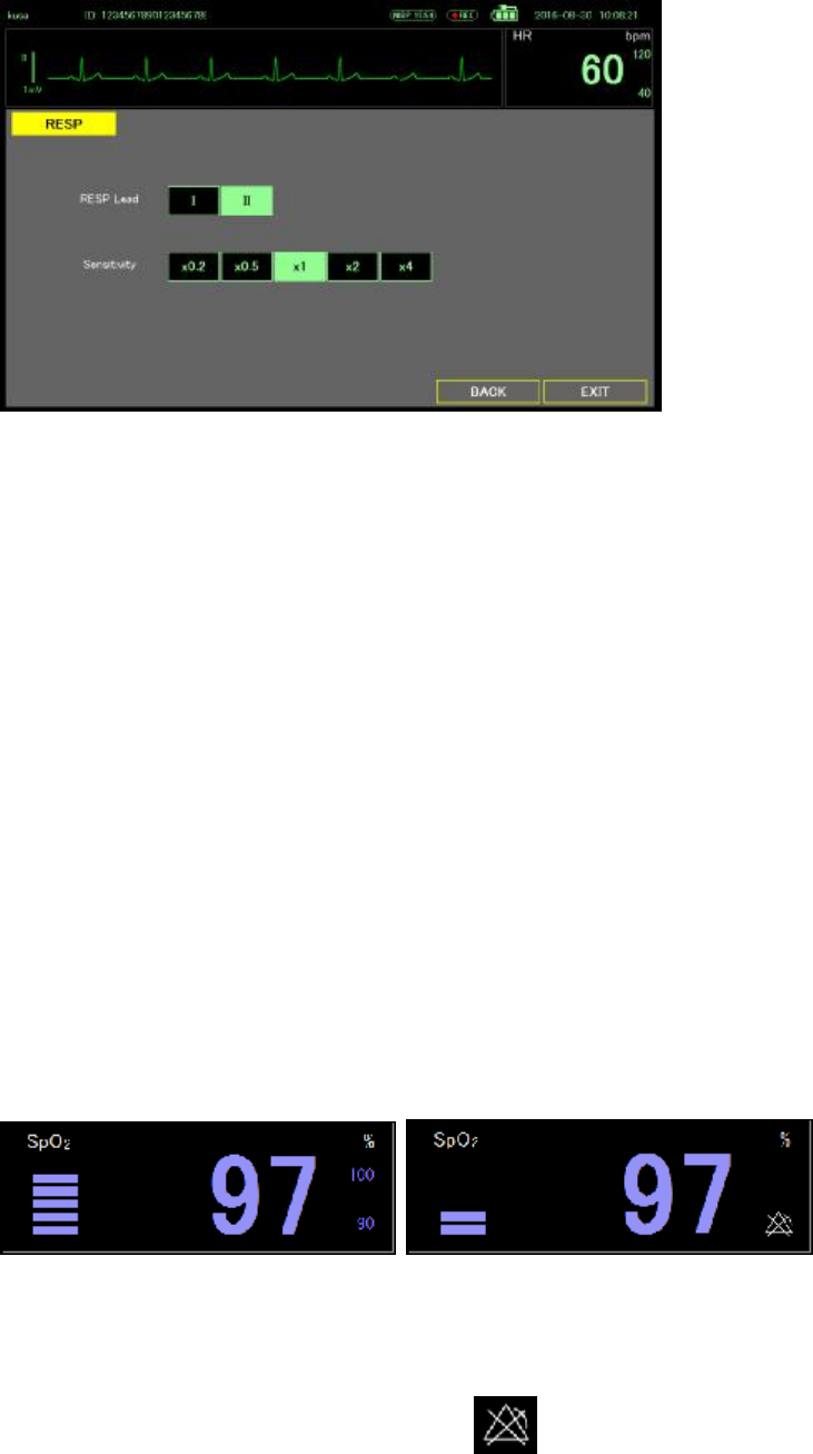
Page 62
4. Select RESP Lead
Respiration Rate is measured with the ECG leads. As the chest expands and contracts
during the respiration cycle, the resistance, or impedance, between the RA-LA
electrodes (Lead I) changes. The result of these changes indicates the respiration rate.
If the respiration waveform is small, change it to lead II (RA-LF).
5. Select Sensitivity.
The amplitude of the respiration waveform is 10 mm with 1-ohm impedance change at
x1.
To detect respiratory rate, a waveform of 3 mm or more is required. Adjust the sensitivity
within the range not picking up heartbeat.
SpO2
SpO2 frame
From the SpO2 frame, you can measure the SpO2% and Pulse Rate (PR).
Located in the under of ECG frame on the Main screen, the SpO2 frame contains data and
features relevant to SpO2. (Main Screen and Large Screen)
Main Screen Alarm ON Alarm OFF
l You can check the SpO2 %
l You can see the oximetry pulse volume, displayed as a vertical bar graph.
l You can see SpO2 % alarm limits. (Upper and Lower), right of the SpO2 %
l If alarm is off, you can see alarm off mark.
l When either of If SpO2 % goes out of the alarm range, the red LED flashes, an alarm
tone sounds and an alarm message is displayed.
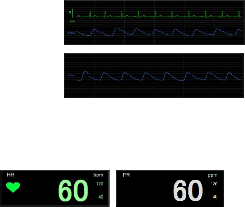
Page 63
Pulse wave display
l The Pulse waveform is always display on the bottom of the Main screen, expect of ECG
1ch, ECG cascade modes.
ECG & SpO2 mode
SpO2 mode
l Amplitude of the pulse wave is automatically adjusted.
l Touch the screen to fix the waveform.
PR display
When pulse only mode is selected, Heart Rate (HR) display changes to Pulse Rate (PR)
display. You can check the Pulse Rate on ECG frame.
HR display PR display
Note When the pulse only mode is selected, ECG and RESP related alarm
are turned off. (Including ECG and RESP lead off warning)
SpO2 and PR Alarm
1. Touch the Menu key.
2. Touch the Alarm Setting key.
3. SpO2 % is displayed in the SpO2 key and the green line on the bar graph.
4. To set the SpO2 alarm limits, use the arrow key on the right side of the screen to follow
these steps:
l Touch the Lower Limit key, change limit using arrow key.
l Touch the Upper Limit key, change limit using allow key.
l Alarm limit is changed immediately.
5. In the pulse only mode, use the arrow on the right side of the screen to set the alarm
limits of the Pulse Rate
6. If you want to turn off the SpO2 alarm, press the SpO2 key to make it black.
7. If you want to turn off the PR alarm, press the HR/PR key to make it black.
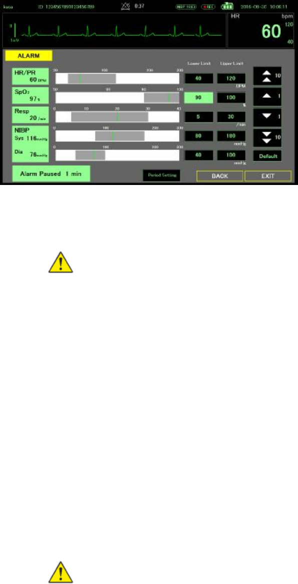
Page 64
Measure SpO2 and pulse rate
SpO2 and pulse rate monitoring continuously measures saturation level of oxygen in
hemoglobin as well as the pulse in a patient through a pulse Oximeter.
WARNING The accuracy of the SpO2 measurement can be affected by
any of the following:
l The presence of significant amounts of dysfunctional hemoglobin,
such as carboxyhemoglobin or methemoglobin
l The presence of concentrations of some intravascular dyes, sufficient
to change the patient’s usual arterial pigmentation
l Patient movement
l Patient conditions such as shivering and smoke inhalation
l Painted nails
l Poor oxygen perfusion
l Anemia or low concentrations of hemoglobin
l Hypotension or hypertension
l Severe vasoconstriction
l Shock or cardiac arrest
l Venous pulsations or sudden and significant changes in pulse rate
l Proximity to an MRI environment
l Moisture in the sensor
l Excessive ambient light, especially fluorescent
l Wrong sensor or sensor too tight
1. Verify the SpO2 sensor cable is connected to the monitor.
WARNING Patient injury risk. The SpO2 sensor and extension cables are
intended only for connect to pulse oximetry equipment. Do not attempt to
connect these cables to a PC or any similar device. Always follow the
sensor manufacturer’s directions for use for care and use of the SpO2
sensor.
2. Clean the application site. Remove anything, such as nail polish, that could interfere
with sensor operation.
Note Do not use disposable sensors on patients who have allergic
reactions to the adhesive.
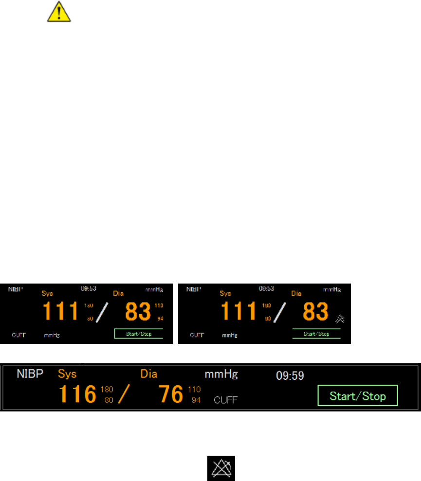
Page 65
3. Attach the SpO2 sensor to the patient according to the manufacturer’s directions for use,
observing all warnings and cautions.
Note If a sterile sensor is required, select a sensor that has been
validated for sterilization, and follow the sensor manufacturer’s
direction for use to sterilize the sensor.
Place the SpO2 sensor and the NIBP cuff on different limbs to reduce unnecessary
alarms when you monitor NIBP and SpO2 at the same time.
Note A range of different sensors is available for different patient
sizes and measurement sites. Consult the SpO2 sensor
manufacturer’s direction for use to select the correct sensor based on
the patient’s weight.
4. Confirm the monitor display SpO2 and pulse rate data within 15 seconds of being
connected to a patient.
WARNING Patient injury risk. Incorrect application or a long duration of
use of an SpO2 sensor may cause tissue damage. Inspect the sensor site
periodically as directed in the sensor manufacturer’s direction for use.
During an SpO2 measurement, the displayed pulse rate is derived from the SpO2
sensor. If SpO2 is not available, the pulse rate is derived from NOBP.
Detaching the sensor during an SpO2 measurement in Monitor mode triggers an alarm.
If SpO2 is being measured continuously on a patient for an extended period, change the
sensor location at least every three hours or as indicated by the sensor manufacturer’s
direction for use.
NIBP
NIBP frame
From the NIBP frame, you can measure blood pressure.
Located in the upper right corner of Main screen, the NIBP frame contains data and features
relevant to noninvasive blood pressure measurement.
Main Screen Alarm ON Alarm OFF
Large Screen
l The frame can display Systolic and Diastolic measurements.
l You can see blood pressure alarm limits. (Upper and Lower)
l If alarm is off, you can see alarm off mark.
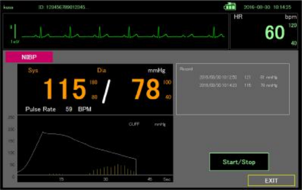
Page 66
l When measuring blood pressure, cuff pressure is displayed and pulsation is indicated
by vertical bar graph.
NIBP measure window
Touch the NIBP frame except the start/stop key opens a NIBP Measure window
l The frame can display Systolic and Diastolic measurements.
l You can see blood pressure alarm limits. (Upper and Lower)
l You can see previous NIBP measurement data.
l When blood pressure is measured, a graph of cuff pressure and pulsation is displayed.
NIBP Alarm
1. Touch the Menu key.
2. Touch the Alarm Setting key.
3. Sys Dia is displayed in the NIBP key and the green line on the bar graph.
4. To set the NIBP alarm limits, use the arrow key on the right side of the screen to follow
these steps:
l Touch the Lower Limit key, change limit using arrow key.
l Touch the Upper Limit key, change limit using allow key.
l Alarm limit is changed immediately.
5. If you want to turn off the NIBP alarm, press the NIBP key to make it black.
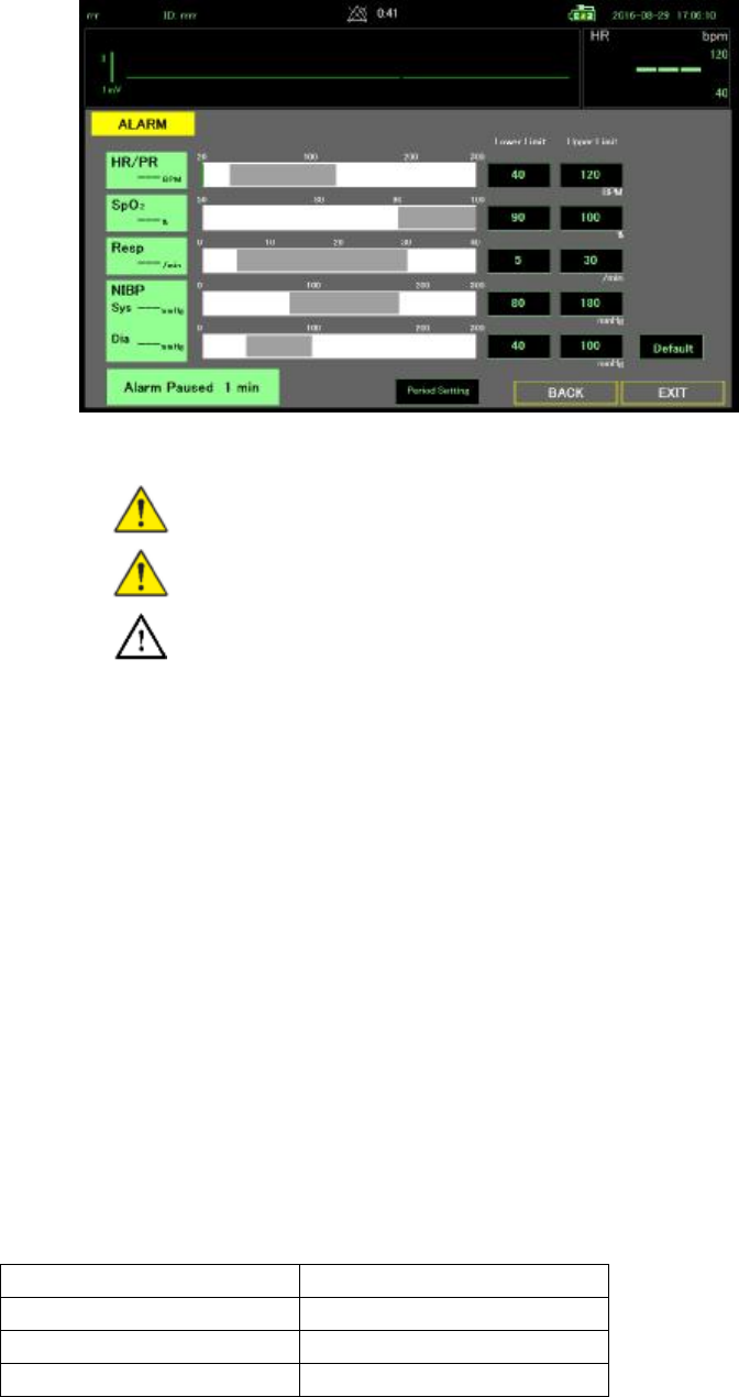
Page 67
Select a cuff
WARNING Use only blood pressure cuffs and hoses listed as approved
accessories to ensure safe and accurate NIBP measurements.
WARNING This blood pressure measurement cannot be used for
neonates and pediatric.
Caution Correct sizing of the blood pressure cuff is important for accurate
blood pressure readings. A cuff that is too small might provide false high
readings, while a cuff that is too large might provide false low readings.
The monitor uses the oscillometric method to determine blood pressure; therefore, if the cuff
extends to the antecubital fossa (bend in the elbow), you can still acquire an accurate blood
pressure reading.
Before taking an NIBP measurement, follow these steps to select the appropriate cuff for the
patient.
1. Measure the circumference of the patient’s bare upper arm. Midway between the elbow
and shoulder.
2. Choose the appropriate cuff size based on the circumference measurement. If the
circumference of the patient’s arm falls between two cuff sizes, use the large cuff size.
3. Cuff size can also be selected using the circumference index at the end of the cuff. The
size of the cuff is fit if the patient's upper arm's end is between the two arrows of the
index mark
4. Wrap the cuff by placing the arterial index mark on the inside of the patient's bare upper
arm.
Cuff measurements
The following tables provide measurement for BriteMed pressure cuffs.
Cuff Circumference (cm)
ADULT-S 17.0 – 25.0
ADULT-M 23.0 – 33.0
ADULT-L 31.0 – 43.0
Position the cuff
Note The monitor and cuffs were validated using the bare upper arm
site.

Page 68
WARNING Patient injury risk. Do not use the NIBP for continuous
monitoring without frequently checking the patient’s limb. When a patient
is being monitored frequently or for a prolonged period, regularly remove
the cuff to inspect it and to check the cuff site for ischemia, purpura, or
neuropathy.
WARNING Inaccurate measurement risk. Do not place the cuff where it
can disturb proper circulation. Do not place the cuff on any area where
circulation is compromised or on any extremity used for intravenous
infusions. Do not use an SpO2 finger clip sensor and a blood pressure cuff
simultaneously on the same limb. Doing so many causes a temporary loss
of pulsation flow, resulting in either no reading or an inaccurate SpO2 or
pulse rate until the flow returns.
WARNING The blood pressure cuff must be properly positioned to ensure
blood pressure accuracy and patient safety. Wrapping the cuff too loosely
(preventing proper inflation) may result in inaccurate NIBP readings.
Caution If a site other than the bare upper arm is used, the blood pressure
measurements may be different. It is important to document the alternate
site on the patient record.
Caution To minimize inaccurate measurement, limit patient movement
during an NIBP measurement cycle.
Before taking an NIBP measurement, follow these steps and select the appropriate cuff for
the patient.
1. Comfortably seated, Legs uncrossed, Feet flat on the floor, Back and arm supported, to
relax as much as possible and not talk during the measurement procedure. Recommend
to have 5 min elapse before the first reading is taken
2. Position middle of the CUFF at the level of the right atrium of the heart
3. Wrap the cuff snugly so that there is room for no more than two fingers between the cuff
and the patient’s bare upper arm.
4. Position the alignment mark on the cuff directly over the brachial artery.
5. Ensure that the blood pressure tubing has no kinks or twists.
NIBP measurement
The monitor enables you to take manual and automatic NIBP measurement
WARNING NIBP readings may be inaccurate for patients experiencing
moderate to severe arrhythmia
WARNING Inaccurate measurement risk. Pulse rate measurements
generated through the blood pressure cuff or through SpO2 are subject
artifact and might not be as accurate as heart rate measurements
generated through ECG or through manual palpation.
Caution Inaccurate measurement risk. Any external compression of the
blood pressure hose or cuff may cause system errors or inaccurate
measurements.
At the start of a measurement, the monitor inflates the cuff to the appropriate level. In the
NIBP frame or NIBP measure window, the cuff display shows the cuff inflation pressure while
the blood pressure measurement is in progress.

Page 69
The monitor measures blood pressure as the cuff is inflating. If patient movement, excessive
noise, or an arrhythmia prevent the monitor from determining the blood pressure while the
cuff is inflating, the monitor inflating the cuff pressure again.
When the measurement is complete, the NIBP frame displays the measurement until you
start another NIBP measurement.
Take a manual NIBP measurement
WARNING Patient injury risk. Never install Luer Lock connectors on
Fukuda Denshi blood pressure cuff tubing. Using these connectors on
blood pressure cuff tubing creates the risk of mistakenly connecting this
tubing to a patient’s intravenous line and introducing air into the patient’s
circulatory system.
Caution Inaccurate measurement risk. Any external compression of the
blood pressure hose or cuff may cause system errors or inaccurate
measurements.
1. Properly size the blood pressure cuff and position it around the patient’s bare upper arm.
2. Touch Start/Stop to take a measurement.
Interval NIBP measurement and other setting
The monitor can take NIBP measurements automatically based on intervals you choose.
The NIBP setting screen provides interval features.
1. Touch the MENU key
2. Touch the NIBP key
3. Select Pressure Pre-set. The cuff inflates to this pressure for the first time. When it can
not be measured, the cuff inflates to 50 mmHg higher pressure.
4. Select Pressure Limit. The cuff does not inflate above this pressure.
5. If you want interval measurement touch Auto Interval ON key.
6. When the Auto Interval is turned on, the interval setting key is displayed and can be set
using the up and down keys
7. Turn on Interval measurement, and when you exit the setting screen the interval timer
starts counting down
8. When the countdown becomes 0, blood pressure is measured.
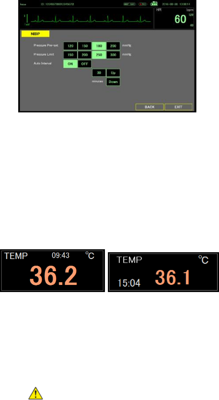
Page 70
When the interval measurement is complete, the NIBP frame displays the measurement
until the next measurement is complete.
The result of the interval measurement is saved as event data.
Note The result of the interval measurement is saved as event data
Note During intervals, each automatic and manual measurements clears all
measurements from NIBP frame.
Temperature
Temperature frame
From the temperature frame you can measure patient temperature.
Located in the middle right of the Main screen, or center of Enlarge screen, the temperature
frame contains data and features relevant to temperature measurement.
Main Screen Enlarge Screen
Temperature measurement display
The frame can display temperature in Celsius or Fahrenheit. You can configure the default
view in Settings. And display measurement time also.
Thermometer
The monitor receives thermometer data via NFC
Thermometer calculates patient's body temperature with thermistor and prediction algorithm.
Take a temperature in the Predictive mode
WARNING Inaccurate measurement risk. To ensure optimal accuracy,
always confirm that the correct mode and site are selected.
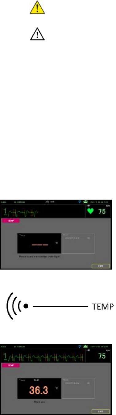
Page 71
WARNING Patient injury risk. Prior to taking a temperature, instruct the
patient not to bite down on the probe as patient injury and damage to the
probe may result.
Caution Probe covers are disposable, nonsterilized, and single-use.
Probes are also nonsterilized. Do not autoclave proves and probe covers.
Ensure that prove covers are disposed of according to facility
requirements or local regulations.
1. Press the power button on the thermometer to turn it on. Sounds urge measurement
2. Insert the probe into a new probe cover.
3. Hold the probe tip in place at the measurement site.
l For oral temperatures, place the probe tip under the patient’s tongue on either side of the
mouth to reach the sublingual pocket and ask the patient to close his/her lips.
l For axillary temperatures, lift the patient’s arm so that the entire axilla is easily seen and
place the probe tip as high as possible in the mid-axilla. Verify that axillary tissue
completely surrounds the probe tip and place the arm snugly at the patient’s side.
4. While the measurement is taking place, the thermometer sounds a tone.
5. The thermometer sounds a burst tone when the final temperature is reached (in
approximately 6 to 15 seconds).
6. Touch the temperature frame, temperature measurement screen displayed.
7. Touch the thermometer to NFC area of the monitor
NFC area
8. Sounds when the monitor receives temperature data from the thermometer. The temperature
measure screen displays the temperature.
9. You can check the previous temperature data on record frame.
Page 72
10. Touch exit to return Main screen, and temperature frame displays the temperature.
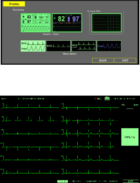
Page 73
12 Lead ECG
In this mode, 12-lead electrocardiogram for measurement is measured with 10 leads cable. 3
lead cable is not suitable to use.
Vital sign alarm does not function because it is not continuous monitoring.
For that reason, Display setting of the MENU is separate from Monitoring.
12 Lead ECG display
12 lead ECG is displayed for limb lead and chest lead for 5 sec.
12 Lead ECG Alarm
12 L ECG does not have HR or arrhythmia alarm, it has only lead-off alarm.
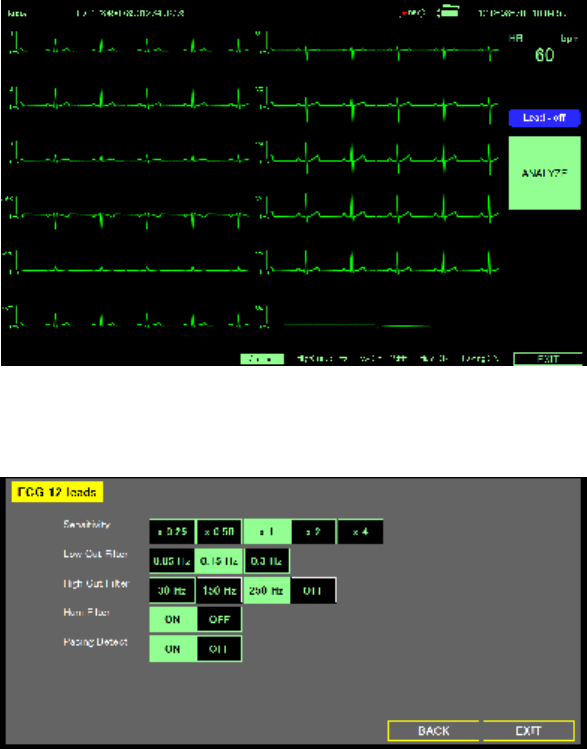
Page 74
12 Lead ECG Setting (Sensitivity, Filter, Pacing Detect)
1. Touch the Menu key.
2. Touch the ECG 12 Leads.
3. You can configure the sensitivity, filter, and pacing detect.
4. Select Sensitivity
The height of the vertical ruler that appears to the left of the ECG waveform indicates 1
mV amplitude and is 10 mm high if x1 is chosen.
5. Select the Low Cut Filter in accordance with the intended use.
l 0.05Hz: This is standard for measurement ECG.
l 0.15Hz: Select when using 12-lead ECG as monitoring instead of diagnosis,
draw less baseline drift.
l 0.3Hz: Select when patient's body movements are large, reduce the baseline
drift.
l 0.3Hz: Select when using in an environment with a lot of ac noise. Waveform
distortion increases.
6. Select the High Cut Filter in accordance with the intended use.
l OFF: This is standard for measurement ECG.
l 250Hz: Select this will reduce fine noise on the waveform
l 150Hz: Select when patient's EMG noise is large, reduce the EMG noise.
l 30Hz: Select when using in an environment with a lot of ac noise. Waveform
distortion increases.
7. Turn on the Hum Filter with the intended use.
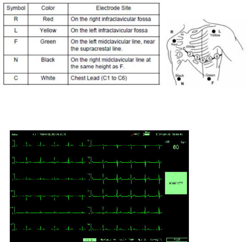
Page 75
Turn on when AC noises enter even if electrode and lead wires are adjusted.
8. Turn on the Pacing Detect with the intended use.
l Used for pacemaker patients.
l Pacing Detection is on, the DS-101 displays pacemaker signals exactly as they are
captured.
12 Lead ECG Electrode Placement
For 12 lead ECG, please place electrode as below graph
12 Lead ECG Measurement
Measurement value can be obtained by pressing the analysis button and measuring the 12L
ECG for 10 seconds
1. Monitor the 12L ECG.
2. If you want to go back to Monitoring mode, Touch EXIT button.
3. Display monitoring condition with bottom area.
4. You can change the sensitivity by touch the Gain button
5. Touch ANALYZE key when ECG waveform stabilizes.
6. Measured value is displayed after taking in the waveform for 10 seconds
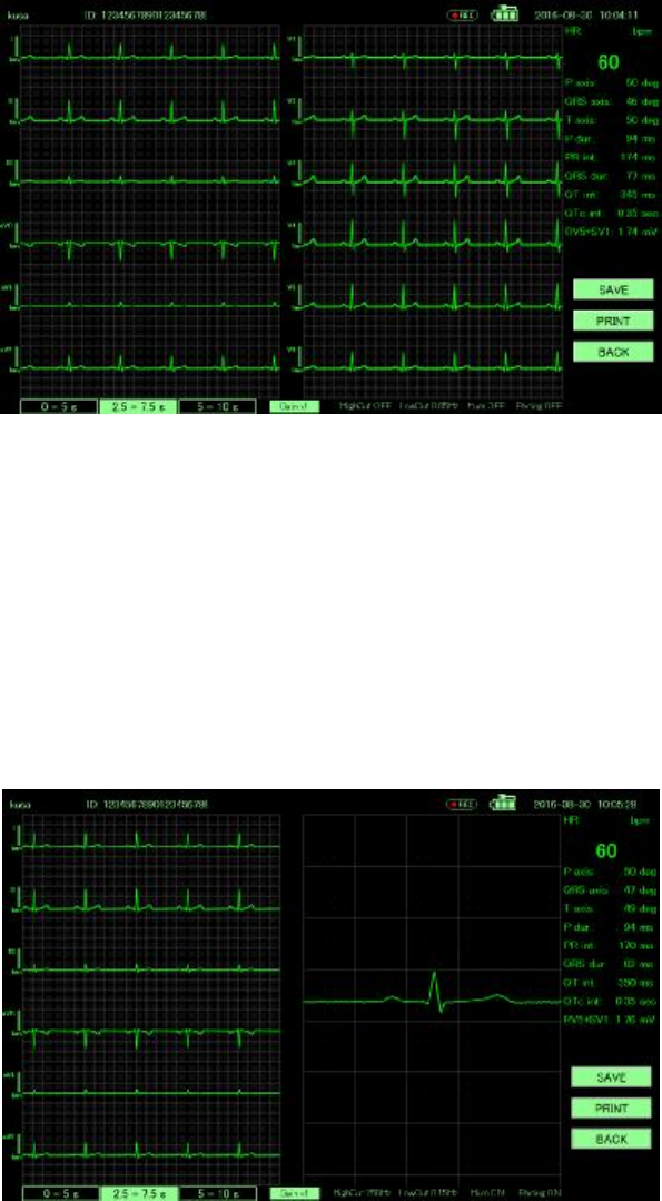
Page 76
7. You can see 7 button
l SAVE: Save 12L ECG waveform with measurement value. Reviewable by List.
l PRINT: Print 12L ECG waveform with measurement value.
l BACJ: Go back to 12L ECG display mode.
l 0 – 5 s: Review 0 – 5sec waveform
l 2.5 – 7.5 s: Review 2.5 – 7.5sec waveform
l 5 – 10 s: Review 5 – 10sec waveform
l Gain: You can change the sensitivity, Touching x1(10mm/s) – x2(20mm/s) –
x4(40mm/s) – x0.25(2.5mm/s) – x0.5(5mm/s) in turn
8. You can see the enlarged waveform by touching the waveform.
9. Print image is as follows.
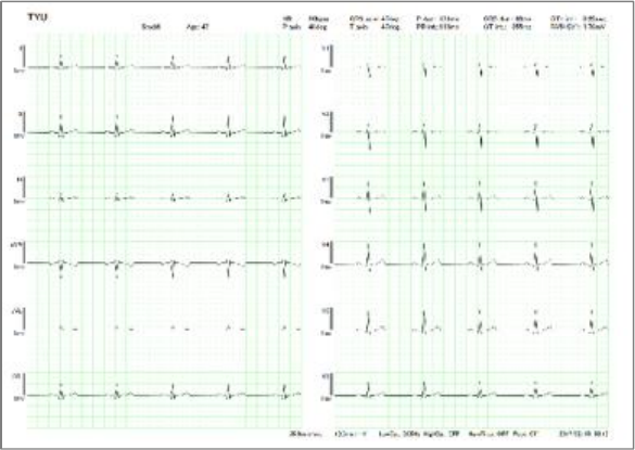
Page 77
12 Lead ECG Measurement Value
You can see 12 lead ECG measurement value are as follows.
HR, QRS axis, P dur, QRS dur, QTc int, P axis, T axis, PR int, QT int, RV5+SV1

Page 78
Specification
Specification
DS-101 Specifications
Specification DS-101
CPU Intel® Celeron® processor N2807
Memory On-board 2 GB 1333 MHz DDR3L
Boot-up Time < 60 seconds
OS Windows Embedded Standard 7
Storage 16 GB SSD mSATA module
OpenGL Supported
Display
Size 10.1” LCD display
Aspect Ratio 16:10
Resolution 1280 x 800
Interface LVDS
Backlight LED
Brightness (cd/m2) 350 (Typ.)
Touch Panel Projected capacitive touch panel
Alarm Noise Sound pressure level over 60 dB(A)
Communication
Wi-Fi 802.11a/b/g/n
Bluetooth Bluetooth v4.0
NFC Reading Distance Within 2 cm
I/O Interface, Button & Indicators
USB Port 1 x USB 3.0
1 x USB 2.0
DC Power Output Micro USB for 5V 2A with USB based define data
transferring for USBBOX
DC Power Input 1 x 15 V DC-in power jack
Power Button Yes
Power LED Yes

Page 79
Specification DS-101
LED Light Bar By embedded controller
Green: heart beat
Red/Yellow/Blue: alarm
Battery
Battery Type 3S1P 103450 tap
Battery Contact Wire
Battery Capacity 10.8 V, 2200 mAh
Battery Life 1 year
Minimum operation time 2 hour
Battery Charge time from
depletion to 90%
About 2 hour
Power
AC Adapter 60601 grade
DC-in Voltage & Current Input: AC 100 V–240 V / 50-60Hz, 0.98A
Output: DC 15 V, 2.4 A
Quick Charging N/A, 0.3C
Power Consumption PCBA: 7 W (typical)
LCD: 3 W (typical)
USB Box: 5 W (typical)
Regulation & Reliability
Safety & EMC IEC 60601-1, 60601-1-2, FCC Class B
Drop Survival 96 cm with package
Operating Temperature 0°C ~ 40°C (32°F ~ 95°F)
Storage Temperature -10°C ~ 60°C (14°F ~ 140°F)
Transportation temperature -10°C ~ 60°C (14°F ~ 140°F)
Operating Humidity 15% ~ 85% relative humidity
Storage Humidity 10% ~ 95% relative humidity
Transportation Humidity 10% ~ 95% relative humidity
IP Protection IP 21
Expected Service Life 5 years
Others
VESA Mount 75 mm x 75 mm
Dimensions (WxHxD) 287.24 mm x 207.23 mm x 24.00 mm

Page 80
Specification DS-101
USB-BOX Specifications
Specification HS-101
IO Board Model USB-BOX-IOBD-R10
ECG Connector ECG connector snap latch fixed socket, 14-pin, green
SpO2 Connector Snap latch fixed socket, 6-pin, blue
NIBP Connector Snap latch fixed socket, gray
Other Interface USB 2.0 Micro-B plug
Defibrillator Protection Yes
Operating Temperature 0 ° C ~ 40°C (32°F ~ 95°F)
Operating Humidity 15% ~ 85% relative humidity
Operating Altitude Up to 3,000 m
Weight 157.5 g
Protection Level IP 21
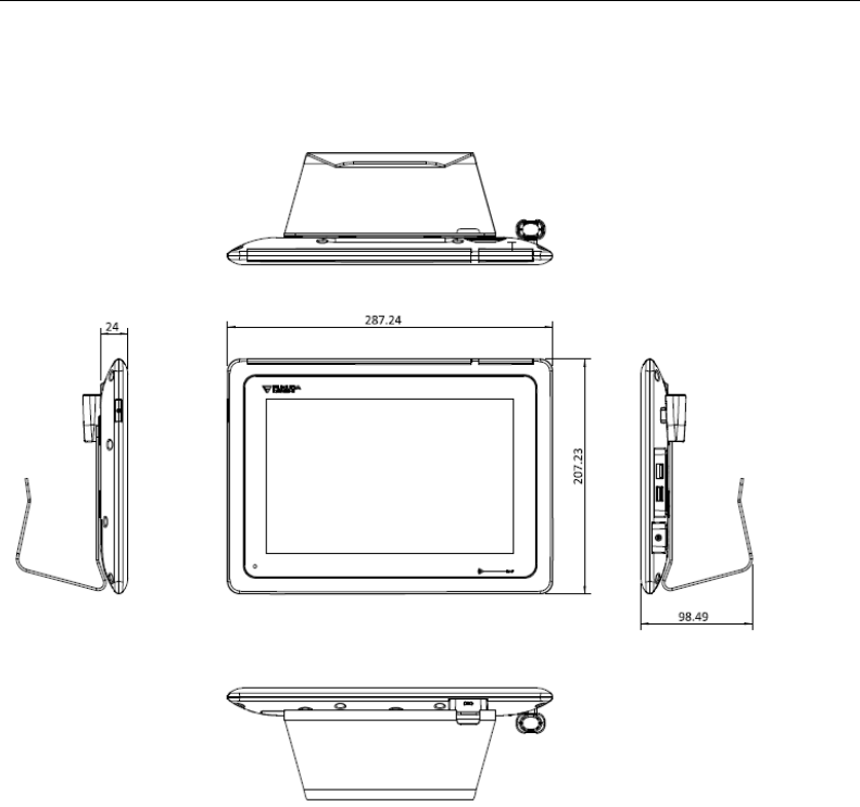
Page 81
Dimensions
The physical dimensions of the DS-101 with stand are show bellow
DS-101 Dimensions (Unit : mm)
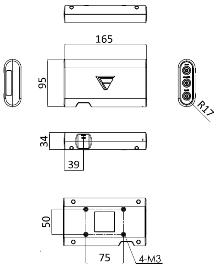
Page 82
The physical dimensions of the USB-BOX are show bellow.
USB-BOX Dimensions (Unit : mm)

Page 83
Standards and compliance
FCC warning
This equipment has been tested and found to comply with the limits for a Class B digital
device, pursuant to Part 15 of the FCC Rules. These limits are designed to provide
reasonable protection against harmful interference in a residential installation. This
equipment generates, uses and can radiate radio frequency energy and, if not installed and
used in accordance with the instructions, may cause harmful interference to radio
communications. However, there is no guarantee that interference will not occur in a
particular installation. If this equipment does cause harmful interference to radio or
television reception, which can be determined by turning the equipment off and on, the user
is encouraged to try to correct the interference by one or more of the following measures:
l Reorient or relocate the receiving antenna.
l Increase the separation between the equipment and receiver.
l Connect the equipment into an outlet on a circuit different from that to which the
receiver is connected.
l Consult the dealer or an experienced radio/TV technician for help.
FCC Caution: Any changes or modifications not expressly approved by the party
responsible for compliance could void the user's authority to operate this equipment.
This device and its antenna(s) must not be co-located or operating in conjunction with any
other antenna or transmitter.
Safety
General Standard EN 60601-1: 1990+A1: 1993+A2: 1995
(Medical Electrical Equipment – Part 1: General
Requirement for Safety)
EMC Standard EN 60601-1-2: 2007
(Medical electrical equipment - Part 1-2: General requirements for
basic safety and essential performance Collateral standard:
Electromagnetic compatibility – Requirements and tests)
Type of protection
against electric shock
Class I Equipment (During AC power operation)
Internally powered Equipment (During battery operation)
Degree of protection
against electric shock
ECG/RESP: Type CF Applied Part
SpO2, NIBP: Type BF Applied Part'
Operation Mode Continuous Operating Equipment
The degree of protection
against ingress of water
IP 21
Protection against Ignition
of Flammable Gas
Not Provided
Performance
This section states the performance of this equipment.
Sound Pressure

Page 84
Alarm Maximum 83.0dB, Minimum 52.0dB
HR Synchronized Tone Maximum 85.0dB, Minimum 32.0dB
ECG
Lead Type Wired 3, 10-electrode
Frequency Characteristic 100Hz/40Hz/18Hz (3-electrode)
250Hz/150Hz/30Hz (10-electrode)
Input Impedance 2.5Mohm and above
Maximum Input Voltage ±5mV
Polarization Voltage ±300mV
Common Mode Rejection Ratio
90dB and above
HR Measurement Range 0, 20 to 300bpm
HR Measurement Accuracy ±1bpm
HR Display Response Time Approx. 6 sec (12 Heartbeat average)
Waveform Size Selection 1/4 (10-electrode only), 1/2, 1, 2, 4 (1 means 10mm/1mV)
Seep Speed 25mm/sec
Auxiliary Output Not Provided
Defibrillation Proof Provided
Heart rate meter accuracy and
response to irregular rhythm
80bpm Ventricular Bigeminy: 80bpm
60bpm Ventricular Bigeminy: 60bpm
120bpm Ventricular Bigeminy: 120bpm
90bpm Bidirectional Bigeminy: 90typ. (89-91) bpm
Response time of heart rate
meter to change in heart rate
HR change from 80bpm to 120bpm: Range 7 to 9 sec., Average 8
sec
HR change from 80bpm to 40bpm: Range 8 to 10 sec., Average 9
sec
Time to ALARM for tachycardia Ventricular Tachycardia 1mVpp, 206bpm: Range 2 to 4 sec.,
Average 3 sec
Ventricular Tachycardia 2mVpp, 206bpm: Range 2 to 4 sec.,
Average 3 sec
Ventricular Tachycardia 0.5mVpp, 206bpm: Range 2 to 4 sec.,
Average 3 sec
Ventricular Tachycardia 2mVpp, 195bpm: Range 2 to 4 sec.,
Average 3 sec
Ventricular Tachycardia 4mVpp, 195bpm: Range 2 to 4 sec.,
Average 3 sec
Ventricular Tachycardia 1mVpp, 195bpm: Range 2 to 4 sec.,
Average 3 sec
Tall T-wave Rejection Capability
1.2mV T-wave can be removed when tested according to
IEC60601-2-27.
Transient Characteristic 3.2 sec, 0.3 sec, 0.1 sec (time constant can be changed)
Rejection of Pacemaker Pulse a) Pacemaker Pulse without Over/Undershoot'
Capable to reject pulses of pulse width 0.1 to 2ms, amplitude
±2mV
b) Pacemaker Pulse with Over/Undershoot
Rejection is not possible.

Page 85
Respiration
Method Impedance Method
Frequency Characteristic 1.5Hz
Current 100μA and below (at 64kHz ±5%)
Measurement Range 0, 4 to 150bpm
Measurement Accuracy ±3rpm
Waveform Size Selection 1/5, 1/2, 1, 2, 4 (1 means 10mm/1Ω)
Seep Speed 1.6mm/sec
SpO2 (Arterial Oxygen Saturation)
Measurement Method 2 Wavelength Pulse Wave Method
Wavelength: Approx. 660nm (red light), Approx.
940nm (Infrared Light)
Output: 15mW and below
Measurement Range 40 to 100%
Resolution 1%
Measurement Accuracy Adult: ±3% when 70 to 100%
PR Measurement Range 20 to 250bpm
PR Accuracy ±3bpm
Measurement Response Time 6 to 7 sec
Measurement Value Update Time 1 sec
Pulse Waveform Size Selection Automatic
Pulse Waveform Seep Speed 25mm/sec
NIBP (Non-Invasive Blood Pressure)
Measurement Method Oscillometric Method
Measurement Range 30 to 280mmHg/4 to 37.3kPa
Resolution 1mmHg
Static Pressure Accuracy ±3mmHg/0.4kPa
BP Measurement Error according to the Clinical Performance Test
Mean Error Within ±5mmHg
Standard Deviation of Error 8mmHg or below
Error of Cuff Pressure Display Within ±3mmHg
PR Measurement Range 40 to 240bpm
PR Accuracy ±2% or ±2bpm (whichever greater)
Safety Mechanism 300mmHg or above

Page 86
Electromagnetic Compatibility
The performance of this device under electromagnetic environment complies with EN 60601-1-2: 2007.
Precautions for Safe Operation under Electromagnetic
Influence
If any sorts of electromagnetic wave, magnetic field, or static electricity exist around the device, noise
interference
or malfunction of the device may occur. If any unintended malfunction or noise occurs
during monitoring, check the
magnetic influence and take appropriate countermeasures.
The following are examples of the common cause and countermeasures.
WARNING Static Electricity
In a dry environment (room), static electricity is likely to occur. Take the following
countermeasures.
l Both operator and patient should remove any static electricity before entering the
room.
l Humidify the room.
WARNING Cellular Phone
l The radio wave may cause malfunction to the device.
l Cellular phones and radio sets should be turned off in the room (building) where
medical device is located.
Caution Lightning
A lightning nearby may induce excessive voltage to the equipment. If any danger is
suspected;
l Use the uninterruptible power supply system.
l Use the battery.
Caution High frequency noise interference from other device through the power outlet
l Check where the noise is originated and remove it using filtering device, etc.
l Stop using the device that is originating the noise.
l Use other power outlet.
EMC Guidance
Essential Performance
l Display function for ECG and SpO2 waveform and HR, SpO2 and NIBP numeric data
l Alarm function
l Accuracy of measured heart rate
l Accuracy of measured SpO2
l Accuracy of Measured NIBP
Conformity Criteria
Page 87
<IEC60601-2-25> ECG-Electrocardiographs
l ME EQUIPMENT may show temporary DEGRADATION during ESD discharges. Within 10
s the ME EQUIPMENT shall resume normal operation in the previous operating mode,
without loss of any operator settings or stored data, and shall continue to perform its
intended function and maintain ESSENTIAL PERFORMANCE.
l When exposed to electrical fast transients and bursts, via the POWER SUPPLY CORD, the
ME EQUIPMENT shall continue to perform its intended function as described in the
particular standard. Testing of PATIENT CABLES and interconnecting cables specified to
be more than 3m in length may show temporary DEGRADATION during exposure to fast
transients and bursts. Within 10 s the ME EQUIPMENT shall resume normal operation in
the previous operating mode, without loss of any operator settings or stored data, and shall
continue to its intended function as described in the ACCOMPANYING DOCUMENTS. The
ME EQUIPMENT shall comply with the requirements of 201.12.1.101.2 when the signal
CAL20110 of Table GG.1 is applied.
<IEC60601-2-27> ECG / Heart Rate
l ME EQUIPMENT shall comply with subclasses 6.2.1.10 of IEC60601-1-2:2007 and the
accuracy of the detected heart rate shall be 60±6bpm.
l ME EQUIPMENT may show temporary DEGRADATION during ESD discharges. Within 10
s the ME EQUIPMENT shall resume normal operation in the previous operating mode,
without loss of any operator settings or stored data, and shall continue to perform its
intended function and maintain ESSENTIAL PERFORMANCE.
l When exposed to electrical fast transients and bursts, via the POWER SUPPLY CORD, the
ME EQUIPMENT shall continue to display the heart rate. the accuracy of the detected heart
rate shall be 60±6bpm. Testing of PATIENT CABLES and interconnecting cables specified
to be more than 3m in length may show temporary degradation during exposure of fast
transients and bursts. Within 10 s the ME EQUIPMENT shall resume normal operation in
the previous operating mode, without loss of any operator settings or stored data, and shall
continue to display the heart rate. The accuracy of the detected heart rate shall be
60±6bpm.
l When exposed to a conducted radio frequency voltage, via the POWER SUPPLY CORD,
the ME EQUIPMENT shall continue to display the heart rate. the accuracy of the detected
heart rate shall be 60±6bpm. However, PATIENT CABLES are exempt from this
requirement.
<IEC80601-2-30> NIBP
l ME EQUIPMENT shall comply with subclasses 6.2.1.10 of IEC60601-1-2:2007 and the
accuracy of the CUFF pressure shall be 180±2mmHg.
<IEC60601-2-49> Multifunction Monitor
l ME EQUIPMENT may show temporary degradation during ESD discharges. Within 10 s the
ME EQUIPMENT shall resume normal operation in the previous operating mode, without
loss of any operator settings or stored data, and shall continue to perform its intended
function as described in the ACCOMPANYNG DOCUMENTS.
l When exposed to electrical fast transients and bursts(EFT/B), via the POWER SUPPLY
CORD, the ME EQUIPMENT shall continue to perform its intended function as described in
the DOCUMENTS. Testing of PATIENT CABLES, TRANCEDUCER cables and
interconnecting cables specified to be more than 3m in length may show temporary
DEGRADATION during exposure of fast transients and bursts. Within 10 s the ME
EQUIPMENT shall resume normal operation in the previous operating mode, without loss of

Page 88
any operator settings or stored data, and shall continue to perform its intended function as
described in the ACCOMPANYING DOCUMENTS .
l When exposed to a conducted radio frequency voltage, via the POWER SUPPLY CORD,
the ME EQUIPMENT shall continue to perform its intended function and maintain
ESSENTIAL PERFORMANCE..
l PATIENT CABLES and TRANSDUCER cables are exempt from this requirement.
<ISO80601-2-61> SpO2
l ME EQUIPMENT shall comply with subclasses 6.2.1.10 of IEC60601-1-2:2007 and shall
continue to provide basic safety and essential performance.
l No permanent degradation or unrecoverable loss of function, due to damage of ME
EQUIPMENT or software, or loss of data shall be observed at any IMMUNITY TEST
LEVEL.
l Operation within the specified measurement accuracy limits (SpO2=90±5%, SpO2_PR=60
±3bpm) or generation of a technical alarm condition.
l In the event of disruption during IMMUNITY tests of IEC60601-1-2 6.2.2, 6.2.4, 6.2.5 and
6.2.7 may show temporary degradation. Within 30 s the ME EQUIPMENT shall resume
normal operation in the previous operating mode, without loss of any operator settings or
stored data, and shall continue to perform its intended function.
This equipment complies with EN 60601-1-2: 2007. However, if portable transmitter or wireless
LAN equipment is used extremely nearby, the electromagnetic influence may largely exceed the
compliance level and may cause unexpected phenomenon such as noise interference on the
waveform, etc.
This equipment should be used in a location specified by each medical institution.
If any unexpected noise interference on the waveform or failure to the peripheral device occurs,
stop using the equipment and follow the instruction of the technical engineer.
The following is the information relating to EMC (Electromagnetic Compatibility).
(When using this equipment, verify that it is used within the environment specified below.)
Compliance to the Electromagnetic Emissions
The DS-101 is intended for use in the electromagnetic environment specified below. The
customer or the user of the DS-101 System should assure that it is used in such an environment.
Guidance and Manufacturer’s Declaration – Electromagnetic Emissions
Emission Test Compliance Electromagnetic Environment - Guidance
RF Emissions
EN 55011
Group 1 The DS-101 uses RF energy only for its internal
function. Therefore, its RF emissions are very
low and are not likely to cause any interference
in nearby electronic equipment
RF Emissions
CISPR 11 Class B
Class B The DS-101 System is suitable for use in all
establishments other than domestic and those
directly connected to the public low-voltage
power supply network which supplies buildings
used for domestic purposes.
Harmonic Emissions
IEC 61000-3-2
Class A
Voltage Fluctuations/
Flicker Emissions
Complies

Page 89
IEC 61000-3-3
Compliance to the FCC
This device complies with Part 15 of the FCC Rules. Operation is subject to the following two
conditions: (1) This device may not cause harmful interference, and (2) this device must accept
any interference received, including interference that may cause undesired operation.
For product available in the USA/Canada market, only channel 1~11 can be operated. Selection
of other channels is not possible.
This device is restricted to indoor use.
This equipment complies with FCC radiation exposure limits set forth for an uncontrolled
environment. This equipment should be installed and operated with minimum distance 20cm
between the radiator & your body.
This module is intended for OEM integrator only and limited to host with brand: Fukuda Denshi
and model: DS-101. The OEM integrator is still responsible for the FCC compliance requirement
of the end product, which integrates this module.
20cm minimum distance has to be able to be maintained between the antenna and the users for
the host this module is integrated into. Under such configuration, the FCC radiation exposure
limits set forth for an population/uncontrolled environment can be satisfied.
Any changes or modifications not expressly approved by the manufacturer could void the user's
authority to operate this equipment.

Page 90
Troubleshooting
General
Can’t boot up and Power Light LED blanking Amber
Cause
System does not have enough battery capacity to boot up
Solution
Press power bottom after charge for 10min
The display is dark, or cannot be seen clearly
Cause
The service life of the LCD backlight has expired.
Solution
The backlight needs to be replaced. Contact our service representative.
The touch panel does not function properly.
Cause
A scratch on the touch panel surface or foreign object entering the touch panel junction is causing
misdetection of the key area.
Solution
The touch panel needs to be replaced. Contact our service representative.
ECG
<LEAD OFF> is displayed
Cause 1
The electrode is detached, or is not making good electrical contact with the skin.
Solution
Check the electrode attachment.
Replace the electrodes.
Check if the lead cable or relay cable is defective (wire break, etc.).
Cause 2
High voltage (abnormal voltage) is detected
Solution
Check the electrode attachment.
Replace the electrodes.
Check if the lead cable or relay cable is defective (wire break, etc.).
Cause 3
Low voltage (abnormal voltage) is detected
Solution

Page 91
Check the electrode attachment.
Replace the electrodes.
Check if the lead cable or relay cable is defective (wire break, etc.).
The ECG waveform is displayed in baseline
Cause 1
Electrode is detached.
Solution
Reattach the electrode. If the electrode contact is poor, replace the electrode.
Cause 2
The lead cable is disconnected from the electrode terminal.
Solution
Securely connect the lead cable.
Respiration
"0" is displayed for respiration rate
Cause
The amplitude of the respiration waveform is too low.
Solution
Change the electrode site, or select a lead with higher QRS amplitude.
SpO2 Measurement
The pulse waveform is not displayed, or interrupted
Cause 1
The amplitude of the pulse waveform is too low, or the sensor is not positioned correctly.
Solution
Check that the light emitting and receiving parts of the sensor LED are aligned.
Cause 2
The sensor is defective.
Solution
Replace the sensor.
Cause 3
SpO2 sensor is not firmly connected to the connector.
Solution
Make sure the SpO2 sensor is firmly connected.
Cause 4
Sensor is exposed to light.
Solution

Page 92
Place a black or dark cloth over the sensor to avoid direct sunlight.When not using the sensor for
measurement, avoid placing the sensor in light or unplug the sensor from the connector.
SpO2 value is unstable
Cause 1
There is excessive body motion from the patient which disables correct measurement.
Solution 1
Have the patient lie still.
Solution 2
Relocate the sensor, or change the sensor to which the body motion will have less influence.
Cause 2
Sensor is exposed to light.
Solution
Place a black or dark cloth over the sensor to avoid direct sunlight.
Non-Invasive Blood Pressure
The cuff is not inflated although the pump is operating.
Cause 1
The air hose is not firmly connected, and the air is leaking.
Solution
Check if the air hose is properly connected.
Cause 2
The cuff size does not match the selected patient type.
Solution
Use the cuff with correct size for the selected patient type.
The pump is not operating.
Cause
The air hose is disconnected from the NIBP Connector.
Solution
Check if the air hose is properly connected.
The measurement data is displayed as "---"
Cause 1
The measurement accuracy is not reliable due to body motion artifact.
Solution
During the measurement, have the patient stay still.
Cause 2
The pulse is too small to acquire reliable measurement accuracy.
Solution

Page 93
Check if the cuff is properly attached to the patient, or cuff size is correct.
Cause 3
The air hose is disconnected.
Solution
Check if the air hose is tightly connected, and then measure again. If the same message is displayed
again, air may be internally leaked.
Contact our service representative.
Temperature
No value display on the screen
Cause 1
Data is not transferring successfully
Solution
Please contact with PC directly with close enough distance and place in the correct location
Cause 2
Thermometer value has been read once
Solution
Please measure and read the value again.

Page 94
Version History