IEI Integration ICEFIRE-T10A TABLET PC User Manual ICEFIRE T10A UMN v1 01 20120210 4 del WWAN
IEI Integration Corp. TABLET PC ICEFIRE T10A UMN v1 01 20120210 4 del WWAN
UserManual.wiki
>
IEI Integration
>
ICEFIRE T10A User Manual
User Manual
Navigation menu
Upload a User Manual
Namespaces
Wiki Guide
HTML
PDF
Info
Views
User Manual
Discussion / Help
Navigation


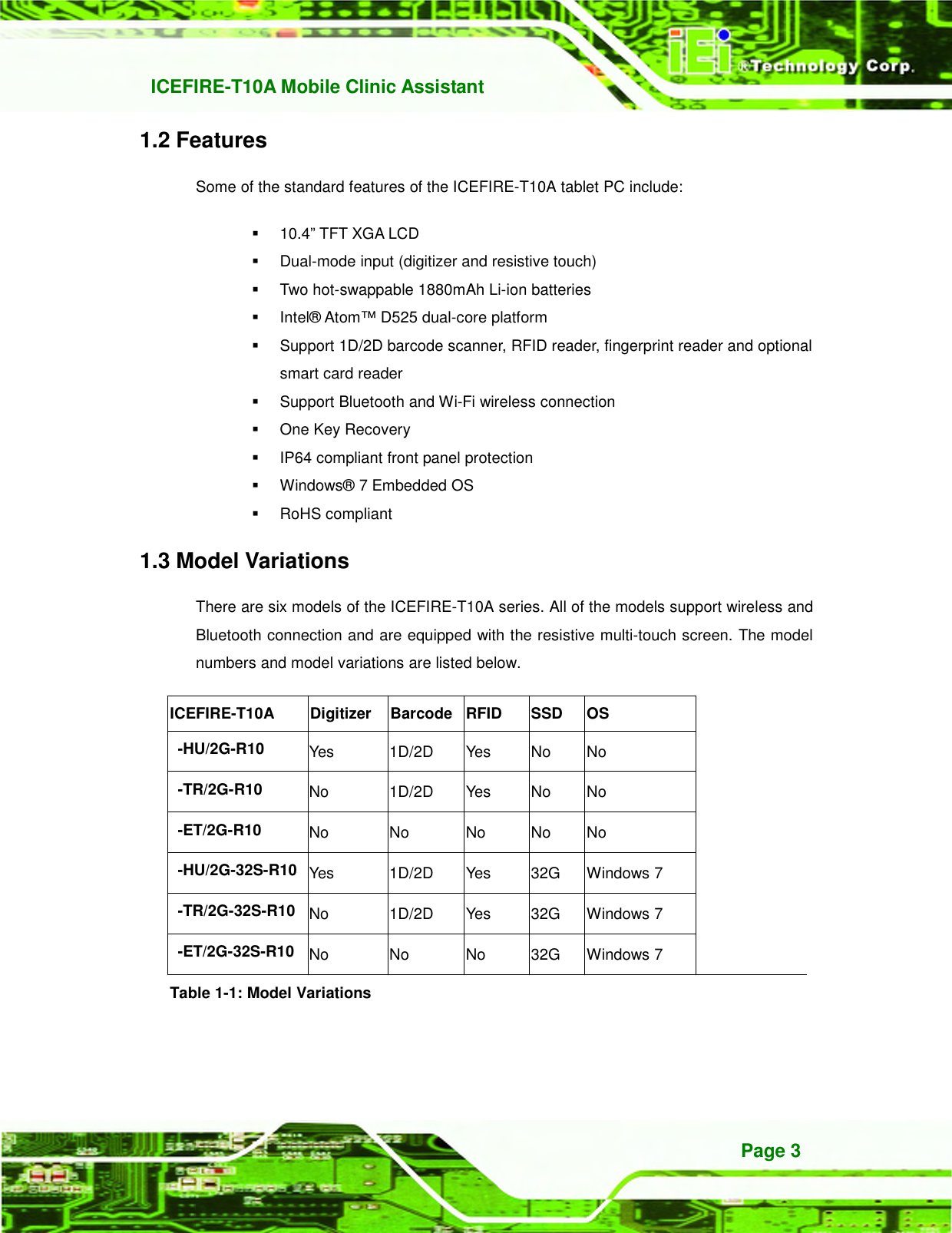
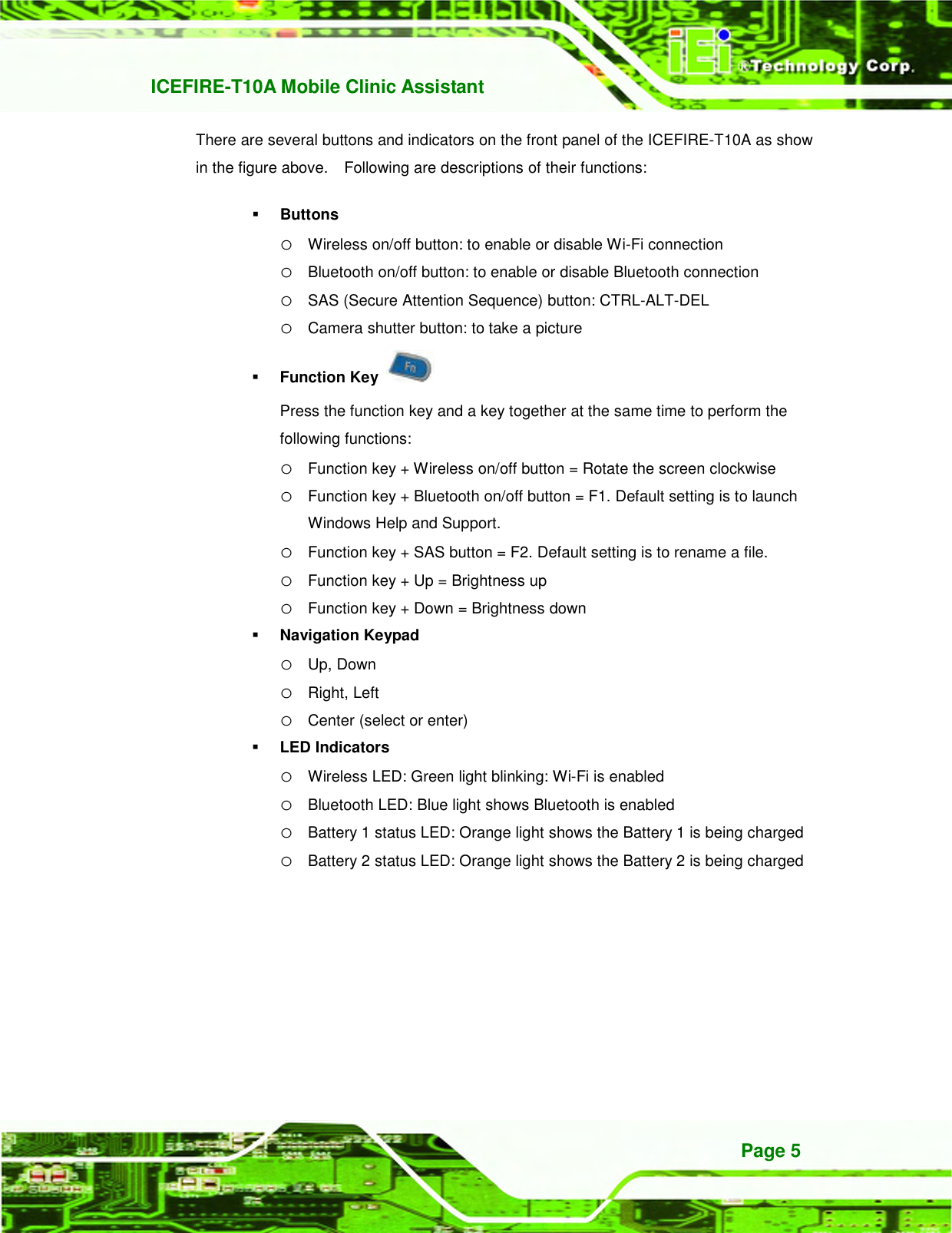


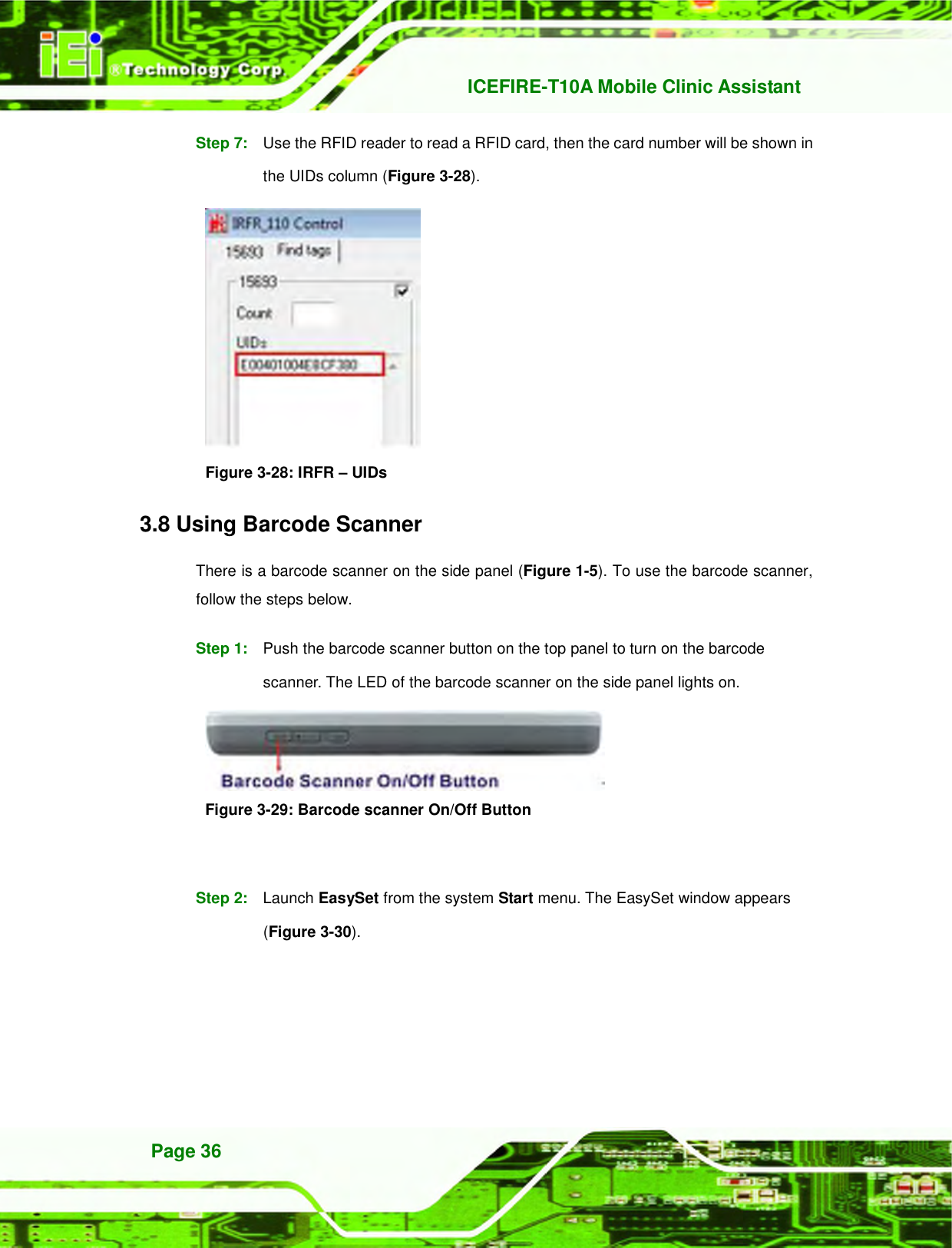


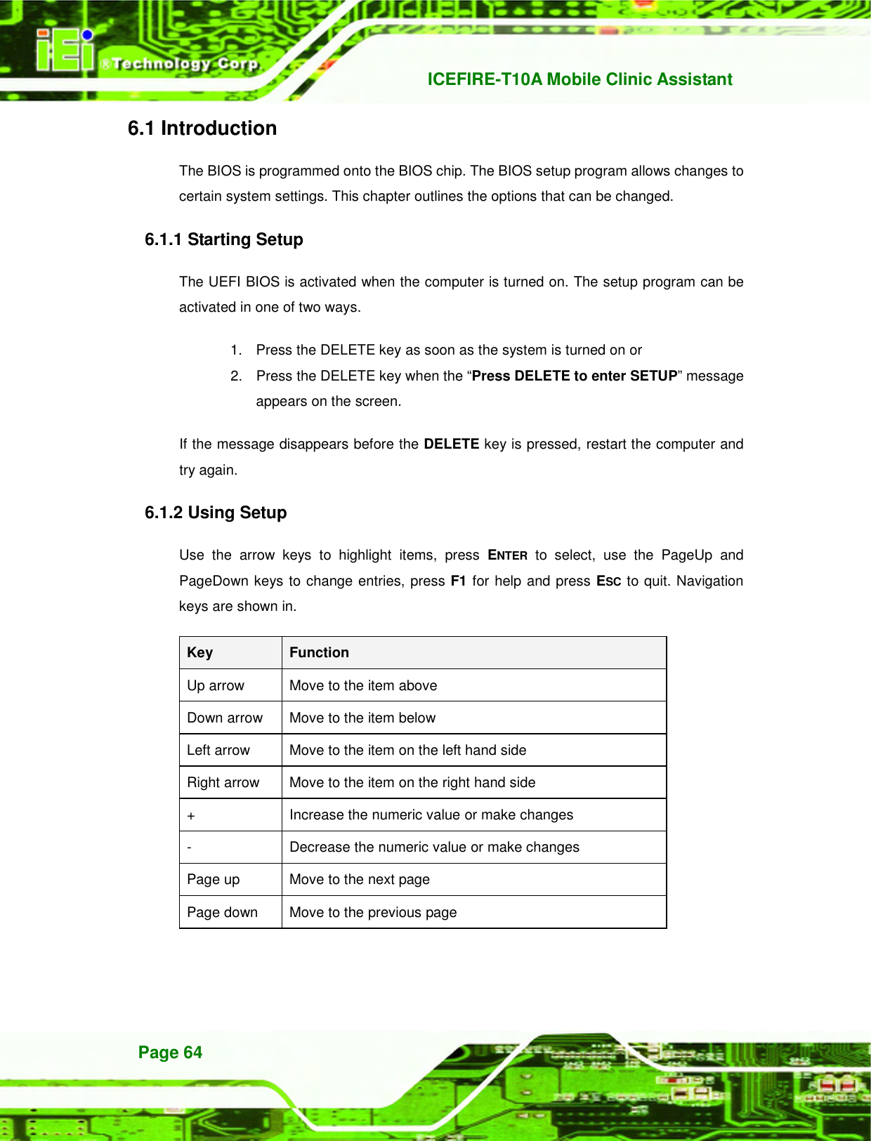
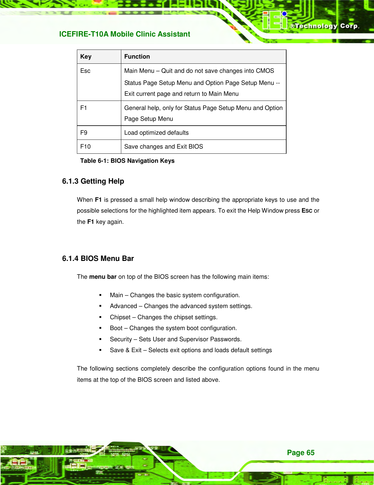
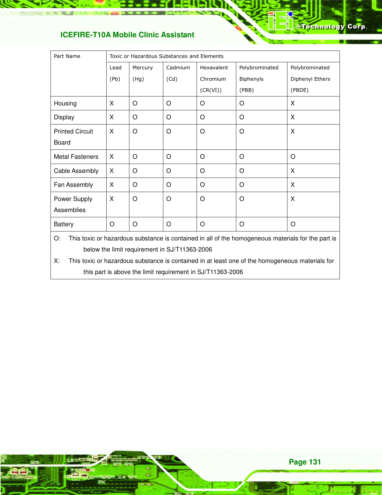
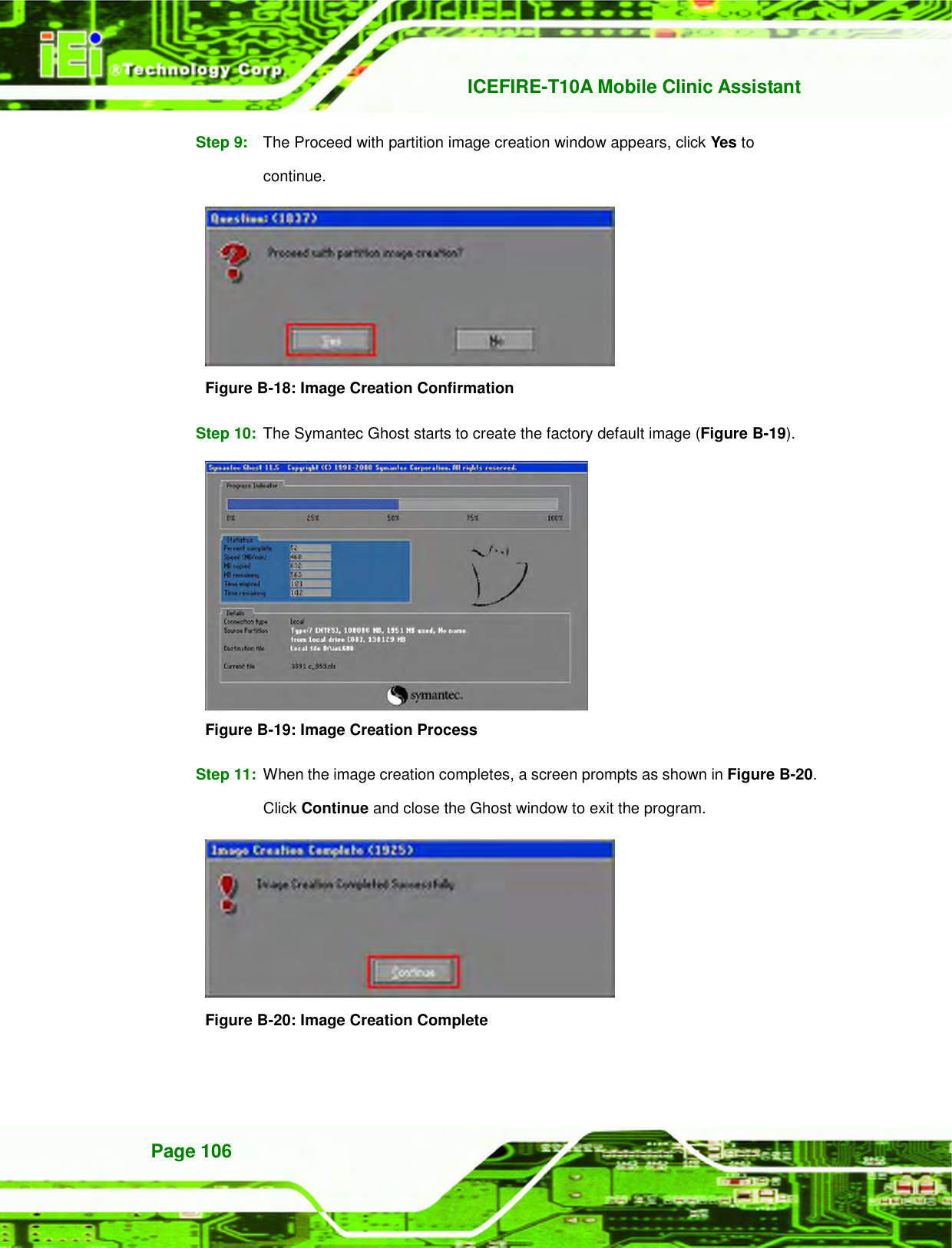
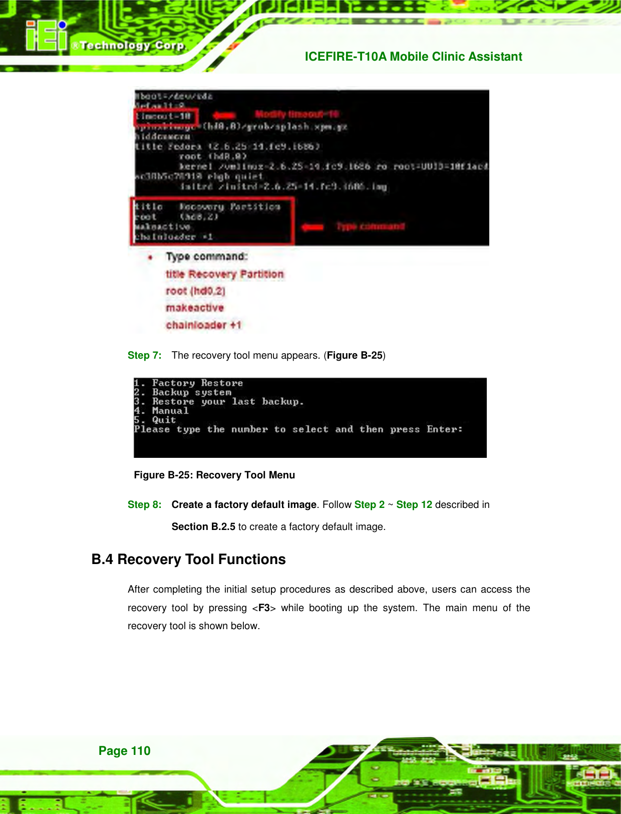
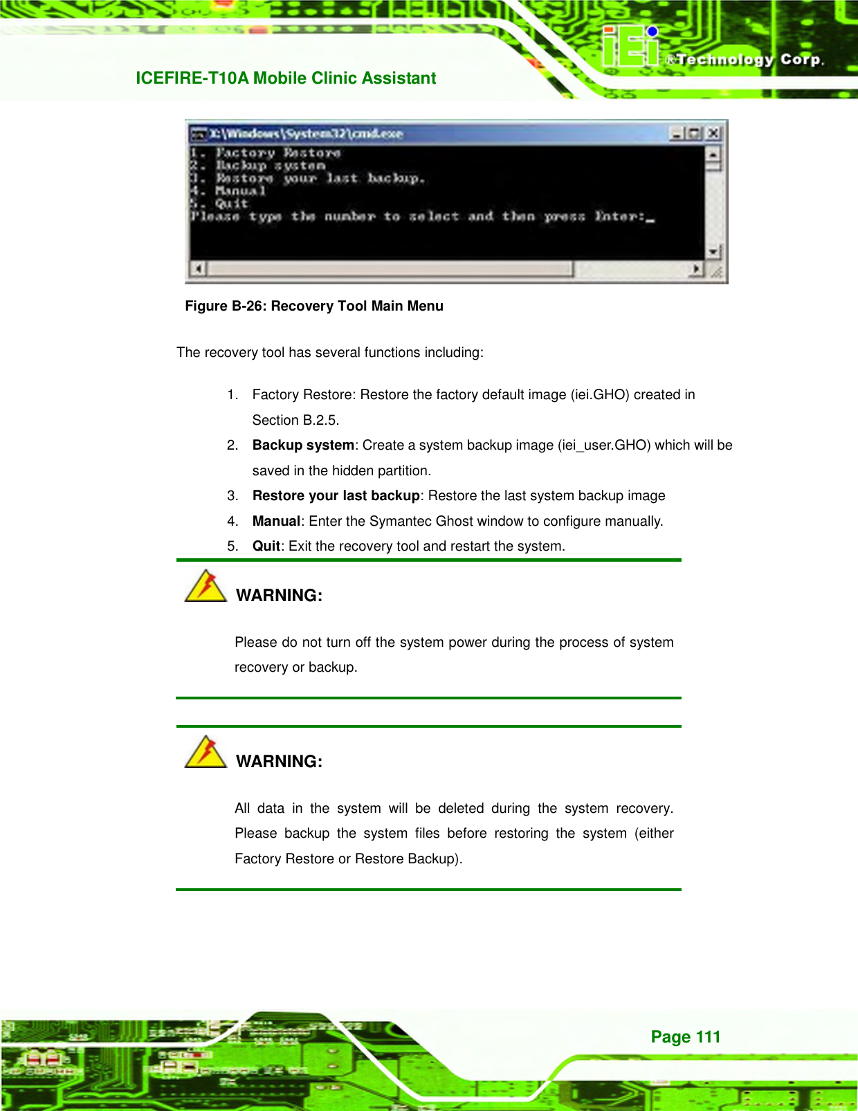
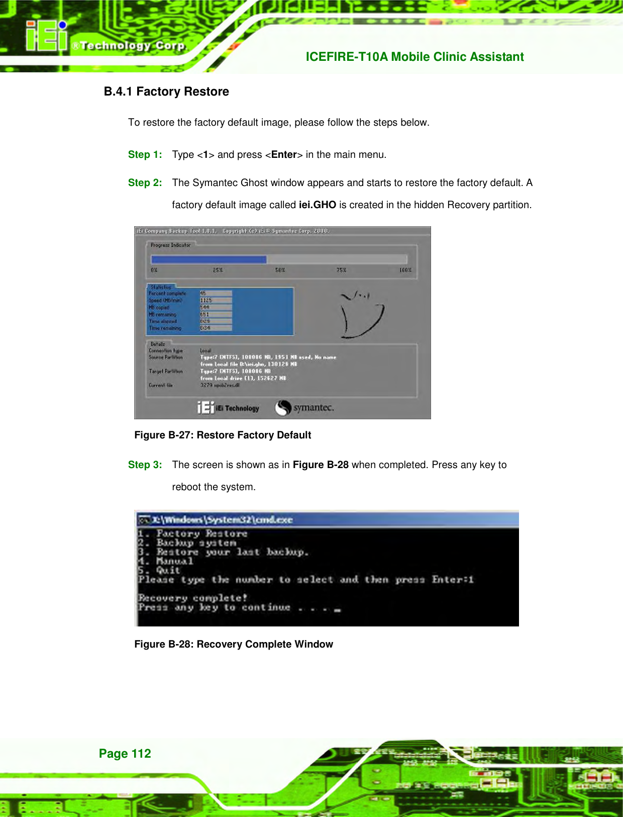
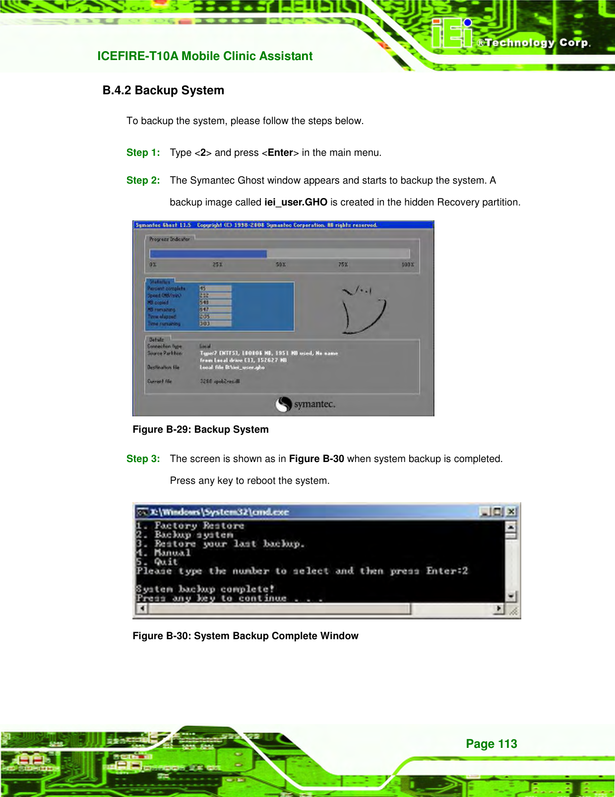
![ICEFIRE-T10A Mobile Clinic Assistant Page 66 6.2 Main The Main BIOS menu (430H510HBIOS Menu 1) appears when the BIOS Setup program is entered. The Main menu gives an overview of the basic system information. Aptio Setup Utility – Copyright (C) 2011 American Megatrends, Inc. Main Advanced Chipset Boot Security Save & Exit BIOS Information BIOS Vendor American Megatrends Core Version 4.6.4.0 0.20 Compliency UEFI 2.0 Project Version H514AR15.ROM Build Date and Time 11/03/2010 15:39:09 iWDD Vendor ICP iWDD Version H514ER15.bin System Date [Tue 07/04/2011] System Time [14:20:27] Access Level Administrator Set the Time. Use Tab to switch between Time elements. ---------------------- : Select Screen ↑ ↓: Select Item Enter Select F1 General Help F2 Previous Values F3 Optimized Defaults F4 Save ESC Exit Version 2.11.1210. Copyright (C) 2011 American Megatrends, Inc. BIOS Menu 1: Main BIOS Information The BIOS Information lists a brief summary of the BIOS. The fields in BIOS Information cannot be changed. The items shown in the system overview include: BIOS Vendor: Installed BIOS vendor Core Version: Current BIOS version Project Version: the board version Build Date: Date the current BIOS version was made The System Overview field also has two user configurable fields: System Date [xx/xx/xx] Use the System Date option to set the system date. Manually enter the day, month and year.](https://usermanual.wiki/IEI-Integration/ICEFIRE-T10A/User-Guide-1695823-Page-78.png)
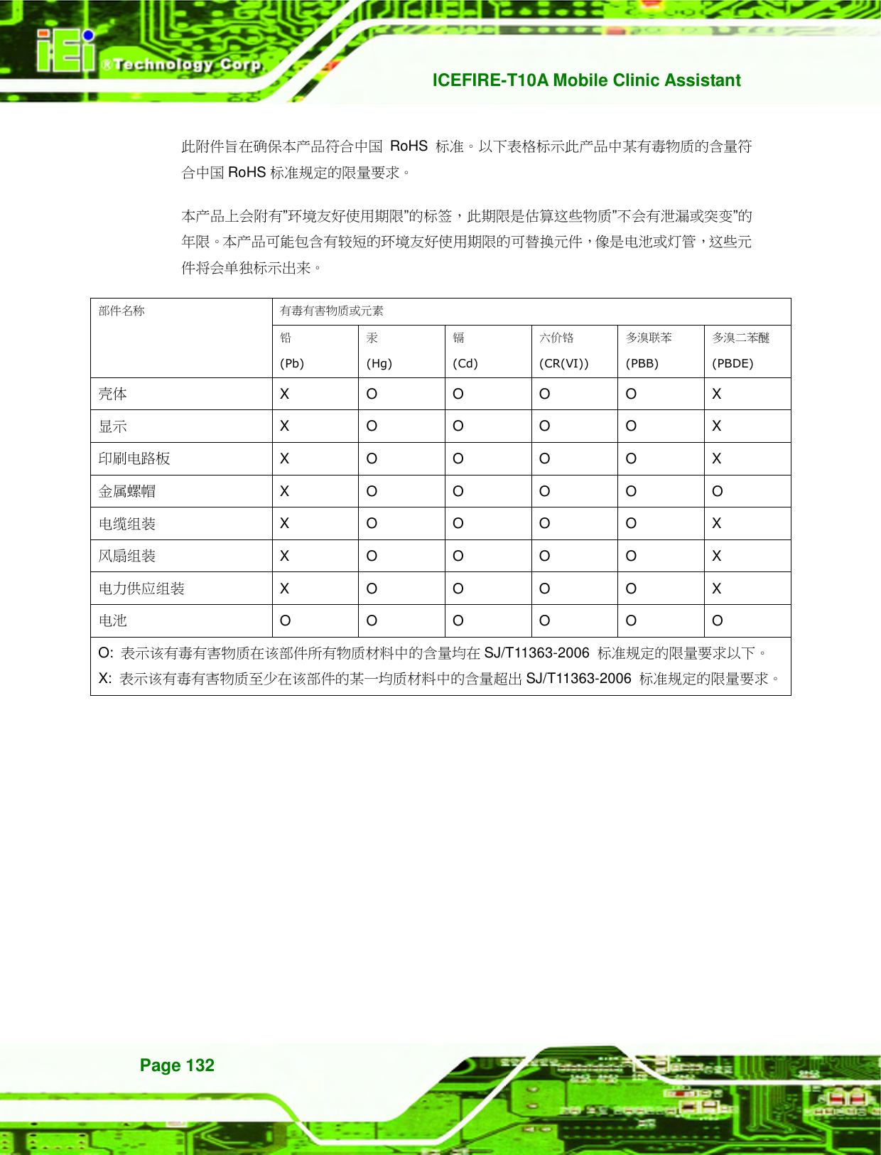
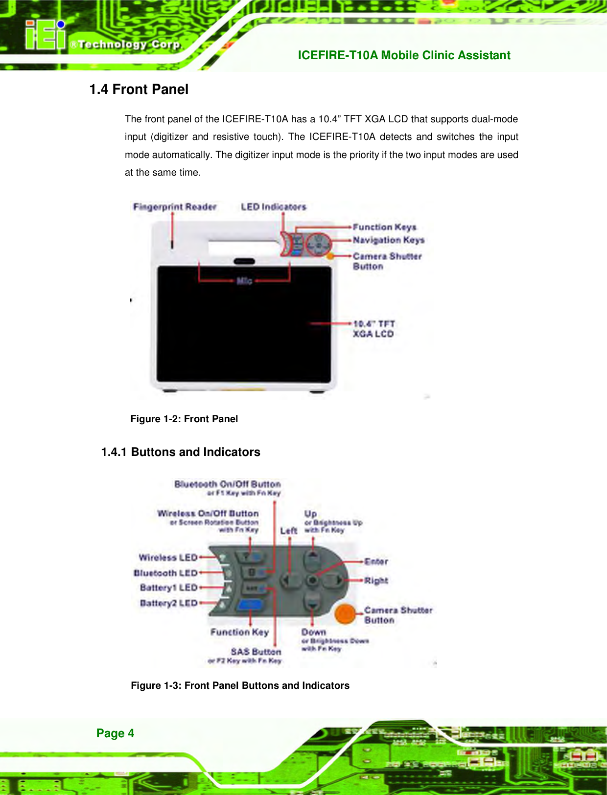
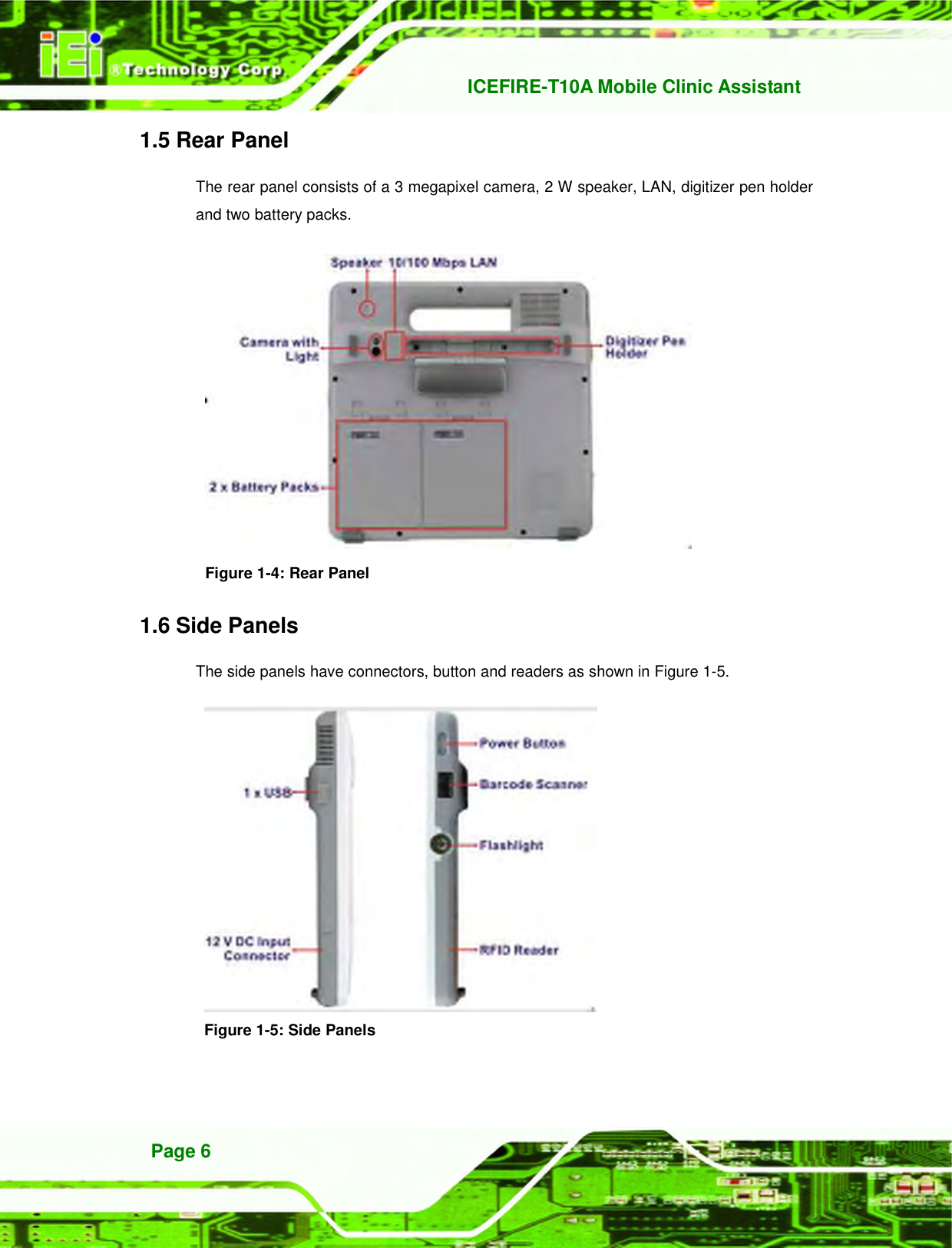
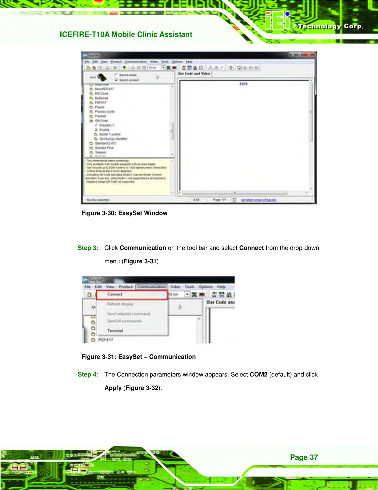
![ICEFIRE-T10A Mobile Clinic Assistant Page 67 System Time [xx:xx:xx] Use the System Time option to set the system time. Manually enter the hours, minutes and seconds. 6.3 Advanced Use the Advanced menu (431H511HBIOS Menu 2) to configure the CPU and peripheral devices through the following sub-menus: WARNING! Setting the wrong values in the sections below may cause the system to malfunction. Make sure that the settings made are compatible with the hardware. Aptio Setup Utility – Copyright (C) 2011 American Megatrends, Inc. Main Advanced Chipset Boot Security Save & Exit > CPU Configuration > IDE Configuration > USB Configuration > H/M Monitor > iEi Feature System ACPI Parameters ---------------------- : Select Screen ↑ ↓: Select Item Enter Select F1 General Help F2 Previous Values F3 Optimized Defaults F4 Save ESC Exit Version 2.11.1210. Copyright (C) 2011 American Megatrends, Inc. BIOS Menu 2: Advanced 6.3.1 CPU Configuration Use the CPU Configuration menu (432H512HBIOS Menu 3) to view detailed CPU specifications and configure the CPU.](https://usermanual.wiki/IEI-Integration/ICEFIRE-T10A/User-Guide-1695823-Page-79.png)
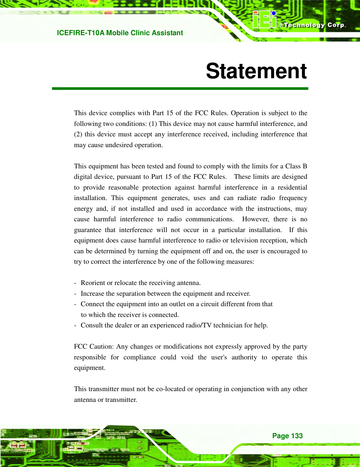
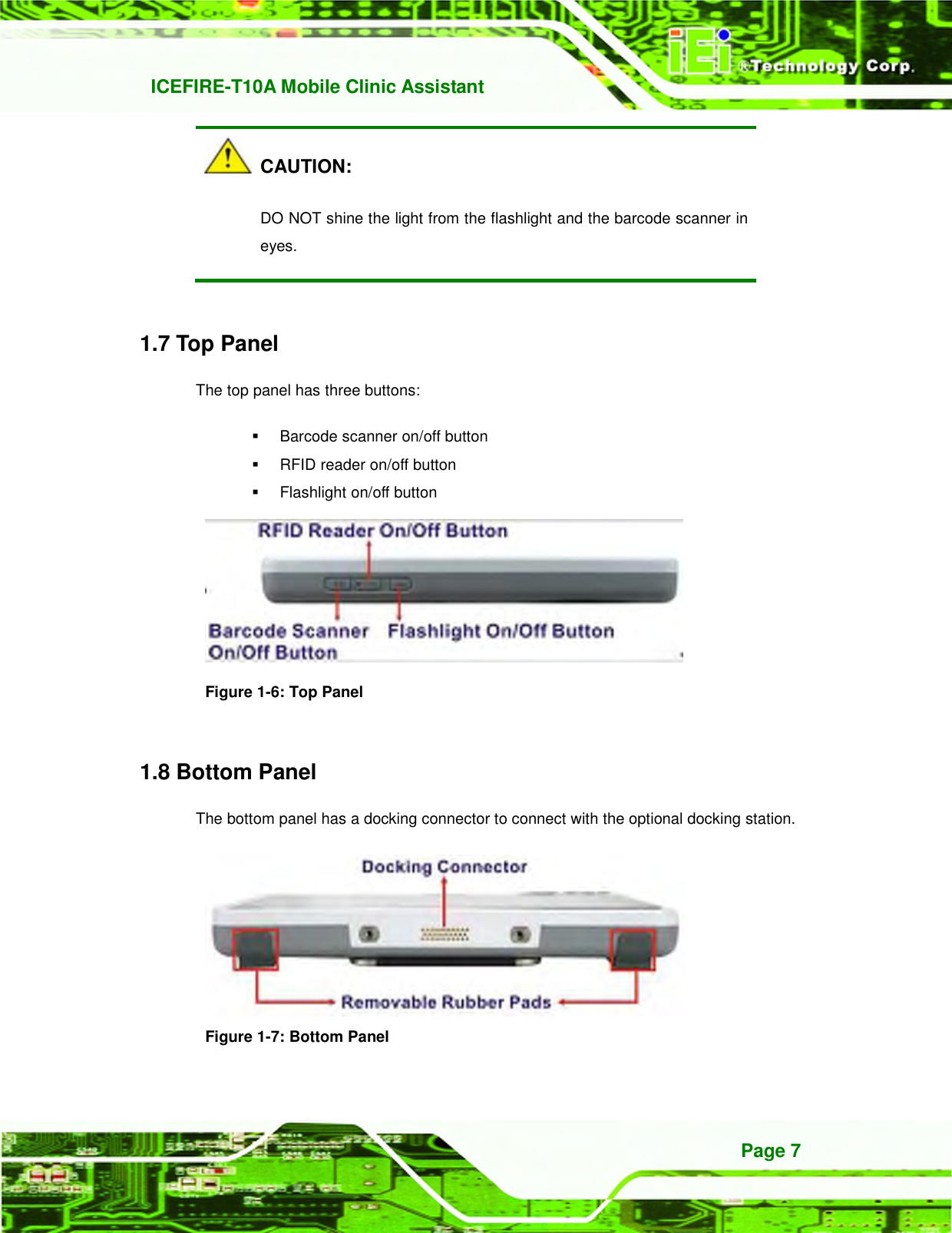
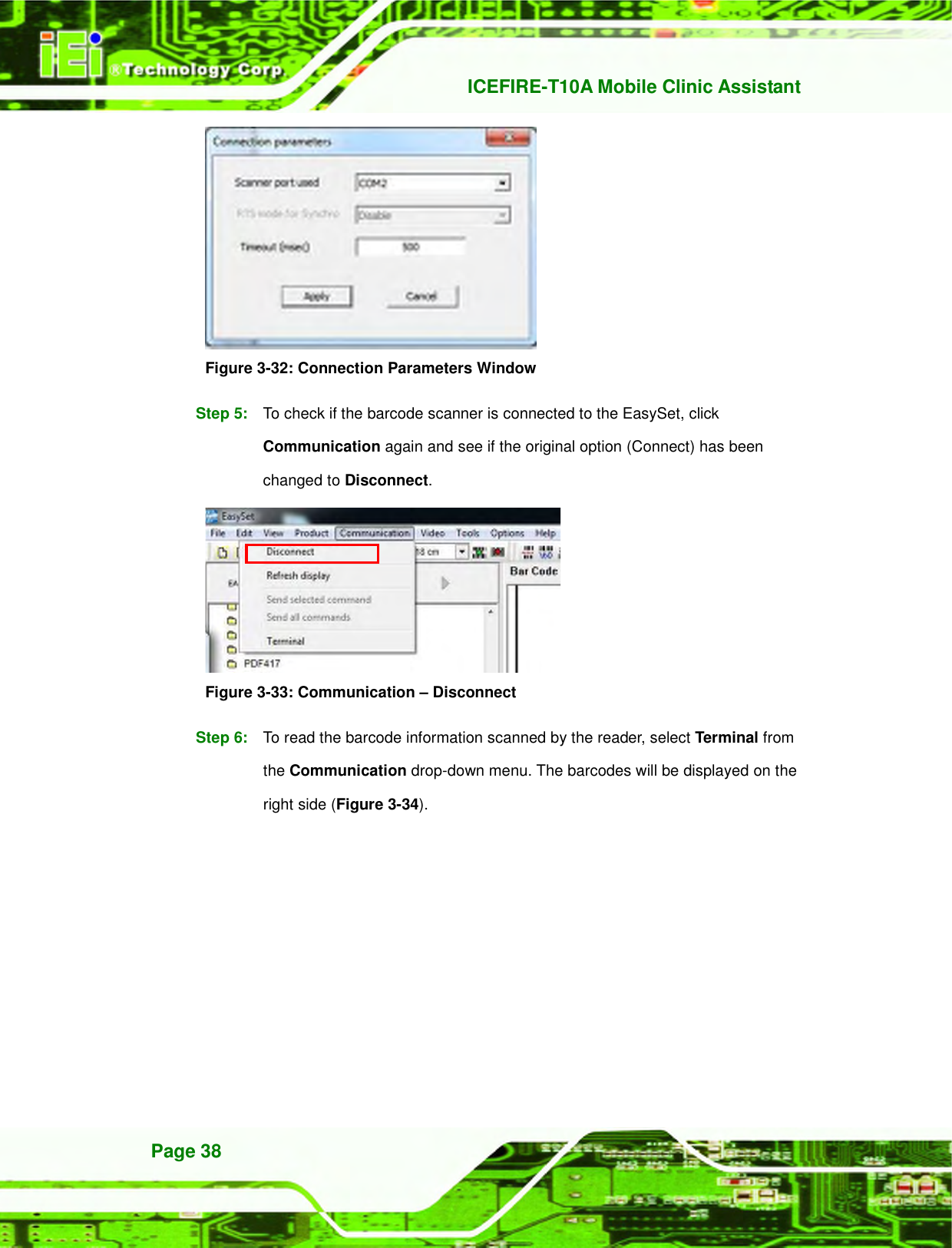
![ICEFIRE-T10A Mobile Clinic Assistant Page 68 Aptio Setup Utility – Copyright (C) 2011 American Megatrends, Inc. Advanced CPU Configuration Processor Type Intel(R) Atom(TM) CPU EMT64 Supported Processor Speed 1800 MHz System But Speed 800 MHz Ratio Status 9 Actual Ratio 9 Processor Stepping 106ca Microcode Revision 263 L1 Cache RAM 2x56 k L2 Cache RAM 2x512 k Processor Cores Dual Hyper-Threading Supported Hyper-Threading [Enabled] ---------------------- : Select Screen ↑ ↓: Select Item Enter Select F1 General Help F2 Previous Values F3 Optimized Defaults F4 Save ESC Exit Version 2.11.1210. Copyright (C) 2011 American Megatrends, Inc. BIOS Menu 3: CPU Configuration The CPU Configuration menu (433H513HBIOS Menu 3) lists the following CPU details: Processor Type: Lists the brand name of the CPU being used EMT64: Indicates if the EM64T is supported by the CPU. Processor Speed: Lists the CPU processing speed System Bus Speed: Lists the system bus speed Processor Stepping: Lists the CPU processing stepping Microcode Revision: Lists the microcode revision L1 Cache RAM: Lists the CPU L1 cache size L2 Cache RAM: Lists the CPU L2 cache size Processor Cores: Lists the number of the processor core Hyper-Threading: Indicates if the Intel® HT Technology is supported by the CPU. Hyper Threading [Disabled] Use the Hyper Threading to enable or disable the CPU hyper threading function. Disabled DEFAULT Disables the use of hyper threading technology](https://usermanual.wiki/IEI-Integration/ICEFIRE-T10A/User-Guide-1695823-Page-80.png)
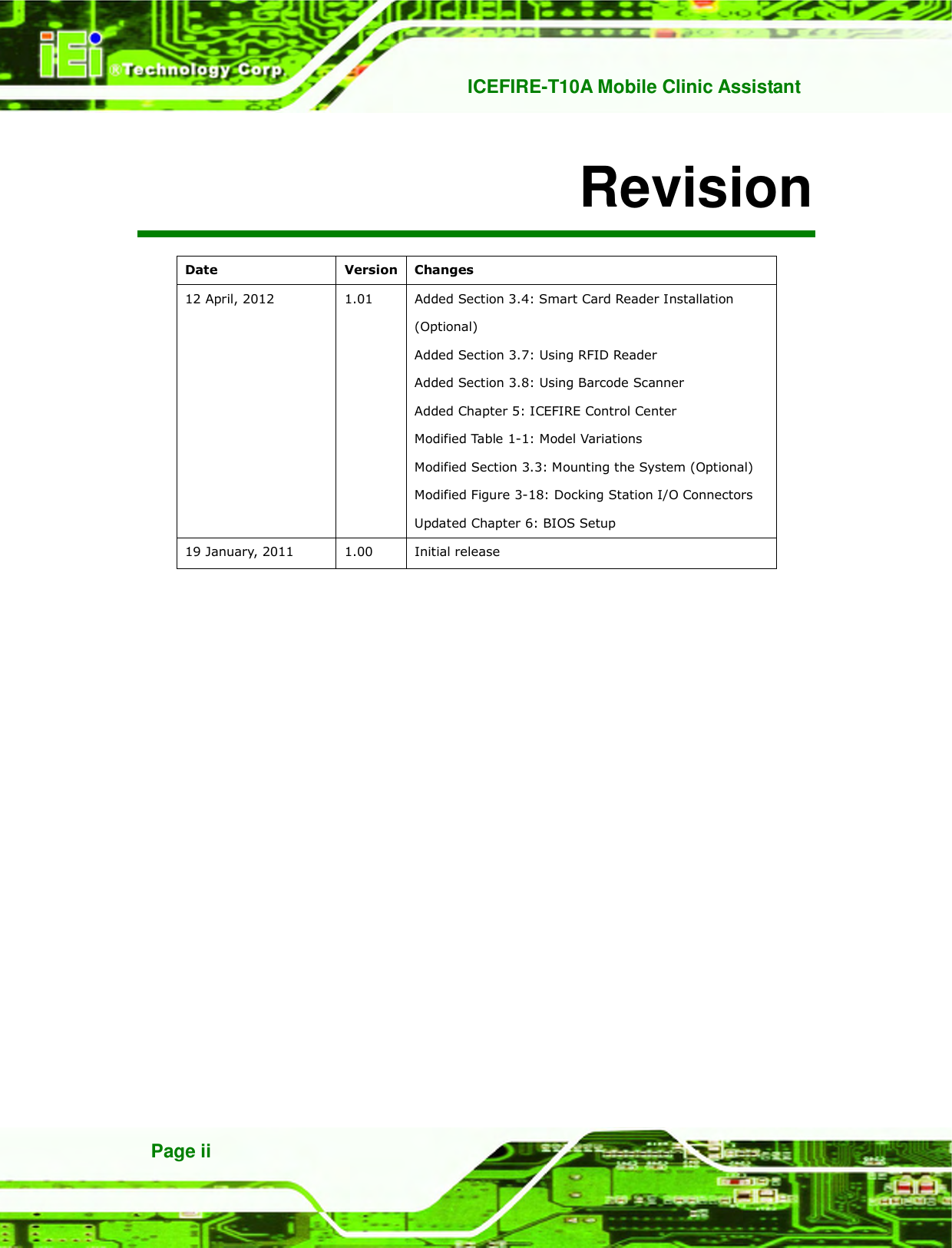
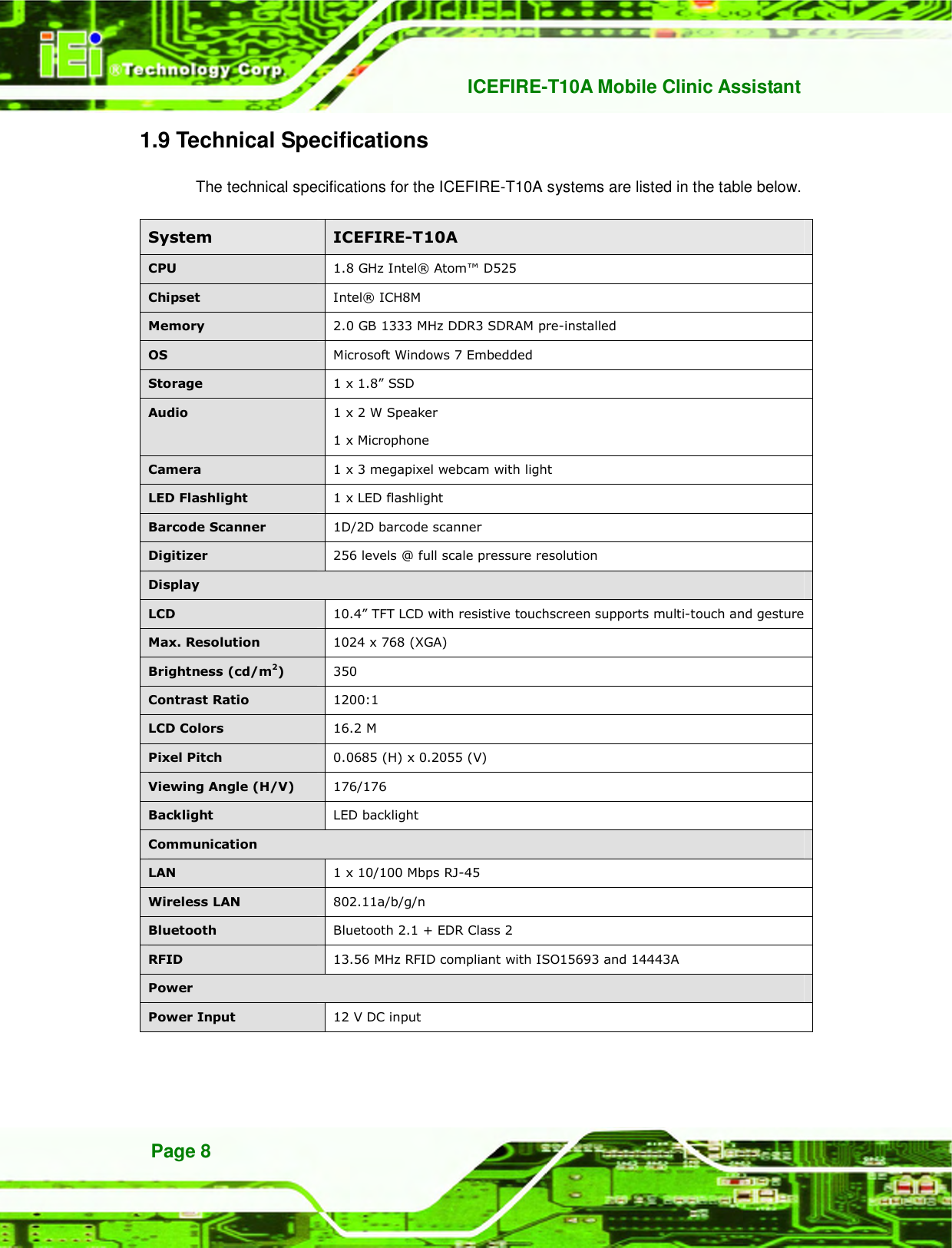
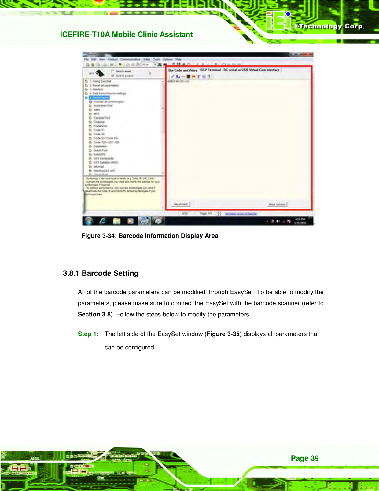
![ICEFIRE-T10A Mobile Clinic Assistant Page 69 Enabled Enables the use of hyper threading technology 6.3.2 SATA Configuration Use the SATA Configuration menu (434H514HBIOS Menu 4) to change and/or set the configuration of the SATA devices installed in the system. Aptio Setup Utility – Copyright (C) 2011 American Megatrends, Inc. Advanced SATA Port0 FiD 1.8 SATA10 (31.9G ATA Or IDE Configuration [Enhanced] Configure SATA as [IDE] (1) IDE Mode. (2) AHCI Mode. (3) RAID Mode. --------------------- : Select Screen ↑ ↓: Select Item Enter Select F1 General Help F2 Previous Values F3 Optimized Defaults F4 Save ESC Exit Version 2.11.1210. Copyright (C) 2011 American Megatrends, Inc. BIOS Menu 4: IDE Configuration ATA Or IDE Configurations [Ehanced] Use the ATA Or IDE Configurations option to configure the ATA/IDE controller. Disabled Disables the on-board ATA/IDE controller. Enhanced DEFAULT Configures the on-board ATA/IDE controller to be in Enhanced mode. In this mode, IDE channels and SATA channels are separated. This mode supports up to 6 storage devices. Some legacy OS do not support this mode.](https://usermanual.wiki/IEI-Integration/ICEFIRE-T10A/User-Guide-1695823-Page-81.png)
![ICEFIRE-T10A Mobile Clinic Assistant Page 70 Configure SATA as [IDE] Use the Configure SATA as option to configure SATA devices as normal IDE devices. IDE DEFAULT Configures SATA devices as normal IDE device. AHCI Configures SATA devices as AHCI device. 6.3.3 USB Configuration Use the USB Configuration menu (435H515HBIOS Menu 5) to read USB configuration information and configure the USB settings. Aptio Setup Utility – Copyright (C) 2011 American Megatrends, Inc. Advanced USB Configuration USB Devices: 1 Keyboard, 2 Hubs Legacy USB Support [Enabled] Enables Legacy USB support. AUTO option disables legacy support if no USB devices are connected. DISABLE option will keep USB devices available only for EFI applications. --------------------- : Select Screen ↑ ↓: Select Item Enter Select F1 General Help F2 Previous Values F3 Optimized Defaults F4 Save ESC Exit Version 2.11.1210. Copyright (C) 2011 American Megatrends, Inc. BIOS Menu 5: USB Configuration USB Devices The USB Devices Enabled field lists the USB devices that are enabled on the system Legacy USB Support [Enabled] Use the Legacy USB Support BIOS option to enable USB mouse and USB keyboard support. Normally if this option is not enabled, any attached USB mouse or USB keyboard](https://usermanual.wiki/IEI-Integration/ICEFIRE-T10A/User-Guide-1695823-Page-82.png)
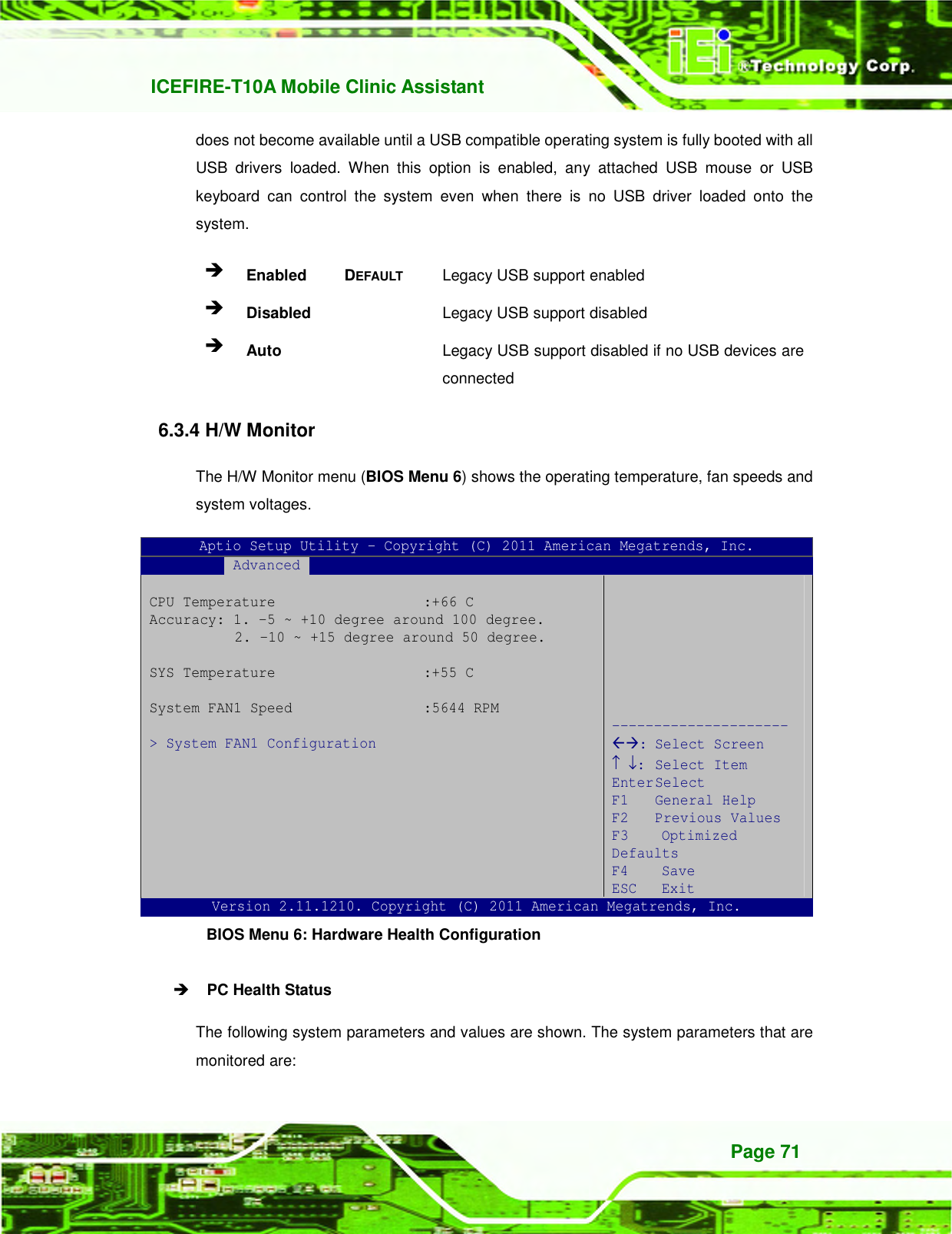
![ICEFIRE-T10A Mobile Clinic Assistant Page 72 CPU Temperature System Temperature System Fan Speed 6.3.4.1 System FAN1 Configuration The System FAN1 Configuration menu (436517HBIOS Menu 7) configures the system fan (FAN1). Aptio Setup Utility – Copyright (C) 2011 American Megatrends, Inc. Advanced PC Health Status CPU Smart Fan control [Auto Mode by PWM] Temperature Of Start 70 Temperature of Off 60 Start PWM 100 Slope (PWM) [1 (PWM)] --------------------- : Select Screen ↑ ↓: Select Item Enter Select F1 General Help F2 Previous Values F3 Optimized Defaults F4 Save ESC Exit Version 2.11.1210. Copyright (C) 2011 American Megatrends, Inc. BIOS Menu 7: Hardware Health Configuration Mode Setting [Full On Mode] Use the Mode Setting option to configure the second fan. Full Mode DEFAULT Fan is on all the time Manual Mode by PWM The fan spins at the speed set in: Manual Setting Auto Mode by PWM The fan adjusts its speed using these settings: Temperature of Start Temperature of Off Start PWM Slope (PWM)](https://usermanual.wiki/IEI-Integration/ICEFIRE-T10A/User-Guide-1695823-Page-84.png)
![ICEFIRE-T10A Mobile Clinic Assistant Page 73 Temperature of Start [070] WARNING: CPU failure can result if this value is set too high When the fan is off, it will only start when the temperature exceeds this setting. Minimum Value: 0°C Maximum Value: 100°C Temperature of Off [060] WARNING: CPU failure can result if this value is set too high The fan will turn off if the temperature falls below this value. Minimum Value: 0°C Maximum Value: 100°C Start PWM [100] This is the initial speed of the fan when it first starts spinning. PWM Minimum Mode: 0 PWM Maximum Mode: 100 Slope PWM [1 PWM] A bigger value will increase the fan speed in big amounts. A smaller value will increase the speed more gradually. 0 PWM 1 PWM 2 PWM](https://usermanual.wiki/IEI-Integration/ICEFIRE-T10A/User-Guide-1695823-Page-85.png)
![ICEFIRE-T10A Mobile Clinic Assistant Page 74 4 PWM 8 PWM 16 PWM 32 PWM 64 PWM 6.3.5 IEI Feature Use the IEI Feature menu (518HBIOS Menu 8) to configure One Key Recovery function. BIOS SETUP UTILITY Main Advanced PCIPNP Boot Security Chipset Exit iEi Feature Auto Recovery Function [Disabled] Select Screen ↑ ↓ Select Item Enter Go to SubScreen F1 General Help F10 Save and Exit ESC Exit v02.61 ©Copyright 1985-2006, American Megatrends, Inc. BIOS Menu 8: IEI Feature Auto Recovery Function [Disabled] Use the Auto Recovery Function BIOS option to enable or disable the auto recovery function of the IEI One Key Recovery. Disabled DEFAULT Auto recovery function disabled Enabled Auto recovery function enabled](https://usermanual.wiki/IEI-Integration/ICEFIRE-T10A/User-Guide-1695823-Page-86.png)
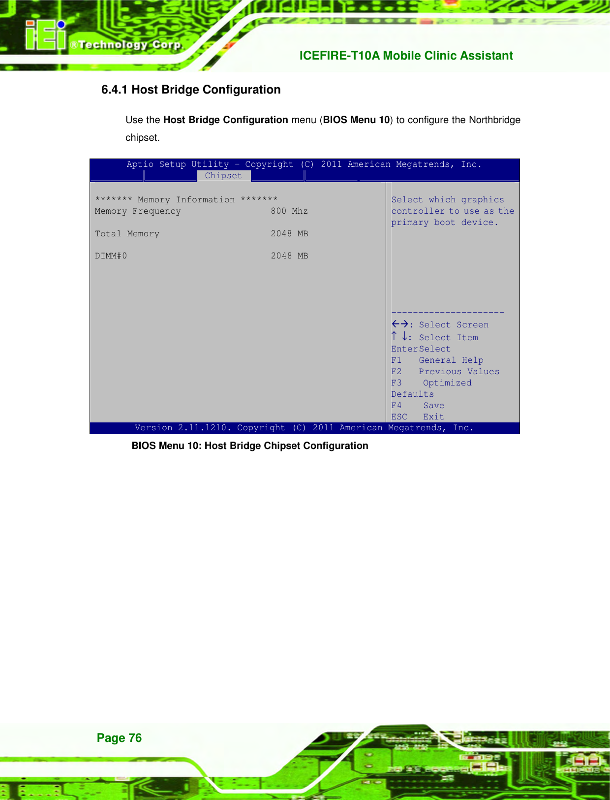
![ICEFIRE-T10A Mobile Clinic Assistant Page 75 6.4 Chipset Use the Chipset menu (437H519HBIOS Menu 9) to access the Northbridge and Southbridge configuration menus WARNING! Setting the wrong values for the Chipset BIOS selections in the Chipset BIOS menu may cause the system to malfunction. Aptio Setup Utility – Copyright (C) 2011 American Megatrends, Inc. Main Advanced Chipset Boot Security Save & Exit RTL8102 PXE Boot [Disabled] > Host Bridge > South Bridge > Intel IGD SWSCI OpRegion North Bridge Parameters --------------------- : Select Screen ↑ ↓: Select Item Enter Select F1 General Help F2 Previous Values F3 Optimized Defaults F4 Save ESC Exit Version 2.11.1210. Copyright (C) 2011 American Megatrends, Inc. BIOS Menu 9: Chipset RTL8102 PXE Boot [Disabled] Use the RTL8102 PXE Boot option to enable or disable the boot option for GbE devices. Disabled DEFAULT Disables the RTL8102 PXE Boot option Enabled Enables the RTL8102 PXE Boot option](https://usermanual.wiki/IEI-Integration/ICEFIRE-T10A/User-Guide-1695823-Page-87.png)
![ICEFIRE-T10A Mobile Clinic Assistant Page 77 6.4.2 South Bridge Configuration Use the South Bridge Configuration menu (438H521HBIOS Menu 11) to configure the Southbridge chipset. Aptio Setup Utility – Copyright (C) 2011 American Megatrends, Inc. Chipset HD Audio Controller [Enabled] USB Function [Enabled] USB 2.0 (EHCI) Support [Enabled] Set Spread Spectrum function [Disabled] HD Audio Controller --------------------- : Select Screen ↑ ↓: Select Item Enter Select F1 General Help F2 Previous Values F3 Optimized Defaults F4 Save ESC Exit Version 2.11.1210. Copyright (C) 2011 American Megatrends, Inc. BIOS Menu 11:South Bridge Chipset Configuration HD Audio Controller [Enabled] Use the HD Audio Controller option to enable or disable the High Definition Audio controller. Enabled DEFAULT The onboard High Definition Audio controller automatically detected and enabled Disabled The onboard High Definition Audio controller is disabled USB Function [Enabled] Use the USB Function BIOS option to enable or disable USB function support. Disabled USB function support disabled Enabled DEFAULT USB function support enabled](https://usermanual.wiki/IEI-Integration/ICEFIRE-T10A/User-Guide-1695823-Page-89.png)
![ICEFIRE-T10A Mobile Clinic Assistant Page 78 USB 2.0 (EHCI) Support [Enabled] Use the USB 2.0 (EHCI) Support BIOS option to enable or disable the USB 2.0 controller. Enabled DEFAULT USB 2.0 controller enabled Disabled USB 2.0 controller disabled Set Spread Spectrum Function [Disabled] The Set Spread Spectrum Function option can help to improve CPU EMI issues. Disabled DEFAULT The spread spectrum mode is disabled Enabled The spread spectrum mode is enabled 6.4.3 Intel IGD SWSCI OpRegion Use the Intel IGD SWSCI OpRegion menu to configure the video device connected to the system. Aptio Setup Utility – Copyright (C) 2011 American Megatrends, Inc. Advanced Intel IGD SWSCI OpRegion Configuration DVMT Mode Select [DVMT Mode] DVMT/Fixed Memory [Maximum] IGD - Boot Type [VBIOS Default] Select DVMT/FIXED Mode Memory size used by Internal Graphics Device --------------------- : Select Screen ↑ ↓: Select Item Enter Select F1 General Help F2 Previous Values F3 Optimized Defaults F4 Save ESC Exit Version 2.11.1210. Copyright (C) 2011 American Megatrends, Inc. BIOS Menu 12: Intel IGD SWSCI OpRegion DVMT Mode Select [DVMT Mode] Use the DVMT Mode Select option to select the Intel Dynamic Video Memory Technology (DVMT) operating mode.](https://usermanual.wiki/IEI-Integration/ICEFIRE-T10A/User-Guide-1695823-Page-90.png)
![ICEFIRE-T10A Mobile Clinic Assistant Page 79 Fixed Mode A fixed portion of graphics memory is reserved as graphics memory. DVMT Mode DEFAULT Graphics memory is dynamically allocated according to the system and graphics needs. DVMT/FIXED Memory [Maximum] Use the DVMT/FIXED Memory option to specify the maximum amount of memory that can be allocated as graphics memory. Configuration options are listed below. 128 MB 256 MB Maximum Default IGD - Boot Type [VBIOS Default] Use the IGD - Boot Type option to select the display device used by the system when it boots. Configuration options are listed below. VBIOS Default DEFAULT CRT (Docking use) LFP CRT + LFP (Docking use)](https://usermanual.wiki/IEI-Integration/ICEFIRE-T10A/User-Guide-1695823-Page-91.png)
![ICEFIRE-T10A Mobile Clinic Assistant Page 80 6.5 Boot Use the Boot menu (439H522HBIOS Menu 13) to configure system boot options. Aptio Setup Utility – Copyright (C) 2011 American Megatrends, Inc. Main Advanced Chipset Boot Security Save & Exit Boot Configuration Boot NumLock State [On] Quiet Boot [Enabled] Boot Option Priorities Boot Option #1 [SATA: FiD 1.8 SATA..] Hard Drive BBS Priorities Enables/Disables Quiet Boot option --------------------- : Select Screen ↑ ↓: Select Item Enter Select F1 General Help F2 Previous Values F3 Optimized Defaults F4 Save ESC Exit Version 2.11.1210. Copyright (C) 2011 American Megatrends, Inc. BIOS Menu 13: Boot Bootup NumLock State [On] Use the Bootup NumLock State BIOS option to specify if the number lock setting must be modified during boot up. On DEFAULT Allows the Number Lock on the keyboard to be enabled automatically when the computer system boots up. This allows the immediate use of the 10-key numeric keypad located on the right side of the keyboard. To confirm this, the Number Lock LED light on the keyboard is lit. Off Does not enable the keyboard Number Lock automatically. To use the 10-keys on the keyboard, press the Number Lock key located on the upper left-hand corner of the 10-key pad. The Number Lock LED on the keyboard lights up when the Number Lock is engaged.](https://usermanual.wiki/IEI-Integration/ICEFIRE-T10A/User-Guide-1695823-Page-92.png)
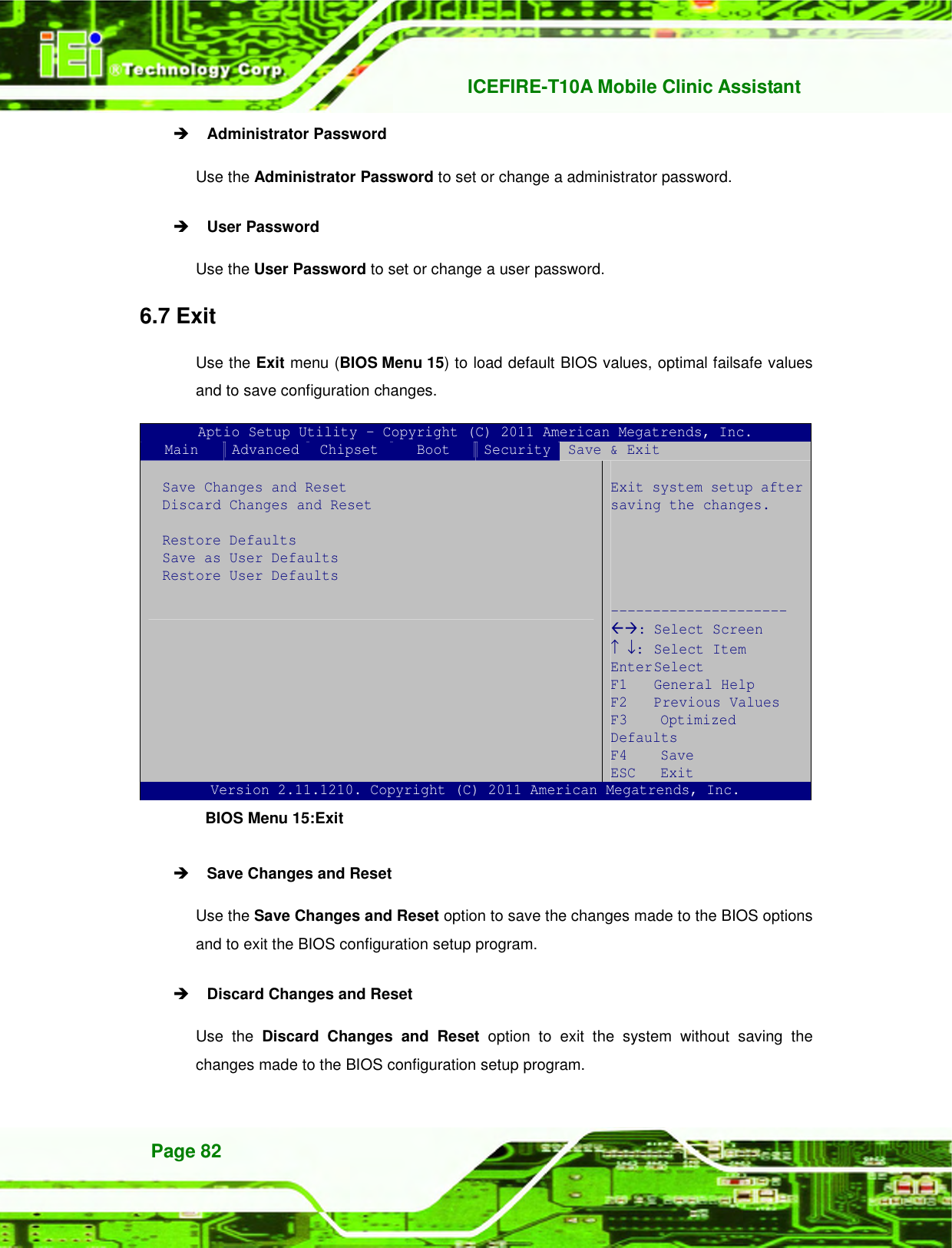
![ICEFIRE-T10A Mobile Clinic Assistant Page 81 Quiet Boot [Enabled] Use the Quiet Boot BIOS option to select the screen display when the system boots. Disabled Normal POST messages displayed Enabled DEFAULT OEM Logo displayed instead of POST messages Boot Option #1 [SATA: FiD 1.8 SATA…] Use the Boot Option #1 option to specify the boot priority from the available devices. Hard Drive BBS Priorities Use the Hard Drive BBS Priorities option to set the order of the legacy devices in this group. 6.6 Security Use the Security menu (440H523HBIOS Menu 14) to set system and user passwords. Aptio Setup Utility – Copyright (C) 2011 American Megatrends, Inc. Main Advanced Chipset Boot Security Save & Exit Password Description If ONLY the Administrator’s password is set, then this only limits access to Setup and is only asked for when entering Setup If ONLY the User’s password is set, then this is a power on password and must be entered to boot or enter Setup. In Setup the User will have Administrator rights. Administrator Password User Password Set Setup Administrator Password --------------------- : Select Screen ↑ ↓: Select Item Enter Select F1 General Help F2 Previous Values F3 Optimized Defaults F4 Save ESC Exit Version 2.11.1210. Copyright (C) 2011 American Megatrends, Inc. BIOS Menu 14: Security](https://usermanual.wiki/IEI-Integration/ICEFIRE-T10A/User-Guide-1695823-Page-93.png)


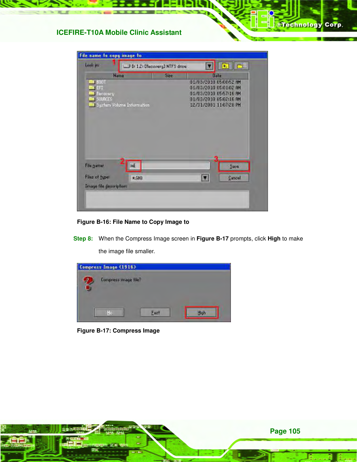
![ICEFIRE-T10A Mobile Clinic Assistant Page 104 Figure B-14: Select a Local Source Drive Step 6: Select a source partition (Part 1) from basic drive as shown in 780H780H461H544HFigure B-15. Then click OK. Figure B-15: Select a Source Partition from Basic Drive Step 7: Select 1.2: [Recovery] NTFS drive and enter a file name called iei (781H781H462H545HFigure B-16). Click Save. The factory default image will then be saved in the selected recovery drive and named IEI.GHO. WARNING: The file name of the factory default image must be iei.GHO.](https://usermanual.wiki/IEI-Integration/ICEFIRE-T10A/User-Guide-1695823-Page-116.png)
![ICEFIRE-T10A Mobile Clinic Assistant Page 120 Below is a list of BIOS configuration options in the BIOS chapter. BIOS Information ............................................................................................................ 66 System Date [xx/xx/xx] ................................................................................................... 66 System Time [xx:xx:xx] .................................................................................................. 67 Hyper Threading [Disabled] ............................................................................................ 68 ATA Or IDE Configurations [Ehanced] ........................................................................... 69 Configure SATA as [IDE] ................................................................................................ 70 USB Devices .................................................................................................................... 70 Legacy USB Support [Enabled] ...................................................................................... 70 PC Health Status ............................................................................................................. 71 Mode Setting [Full On Mode] .......................................................................................... 72 Temperature of Start [070] .............................................................................................. 73 Temperature of Off [060] ................................................................................................. 73 Start PWM [100] ............................................................................................................... 73 Slope PWM [1 PWM] ....................................................................................................... 73 Auto Recovery Function [Disabled] ............................................................................... 74 RTL8102 PXE Boot [Disabled] ........................................................................................ 75 HD Audio Controller [Enabled] ....................................................................................... 77 USB Function [Enabled] ................................................................................................. 77 USB 2.0 (EHCI) Support [Enabled] ................................................................................. 78 Set Spread Spectrum Function [Disabled] .................................................................... 78 DVMT Mode Select [DVMT Mode] ................................................................................... 78 DVMT/FIXED Memory [Maximum] .................................................................................. 79 IGD - Boot Type [VBIOS Default] .................................................................................... 79 Bootup NumLock State [On]........................................................................................... 80 Quiet Boot [Enabled] ...................................................................................................... 81 Boot Option #1 [SATA: FiD 1.8 SATA…] ........................................................................ 81 Hard Drive BBS Priorities ............................................................................................... 81 Administrator Password ................................................................................................. 82 User Password ................................................................................................................ 82 Save Changes and Reset ................................................................................................ 82 Discard Changes and Reset ........................................................................................... 82 Restore Defaults ............................................................................................................. 83 Save as User Defaults ..................................................................................................... 83](https://usermanual.wiki/IEI-Integration/ICEFIRE-T10A/User-Guide-1695823-Page-132.png)