IEI Integration IOVU-570M Panel PC User Manual
IEI Integration Corp. Panel PC
user manual

IOVU-570M Panel PC
Page i
IEI Technology Corp.
User Manual
MODEL:
IOVU-570M
Panel PC
,
5.7"
Touch Screen,
520
MHz Marvell XScale PXA270
,
Fast Ethernet, 2 x USB, 802.11b/g Wireless, RS-232/422/485
RoHS Compliant, IP 64 Protection
Rev. 1.00 – 17 September, 2010
IOVU-570M Panel PC
Page ii
Revision
Date Version
Changes
17 September, 2010 1.00 Initial release
IOVU-570M Panel PC
Page iii
Copyright
COPYRIGHT NOTICE
The information in this document is subject to change without prior notice in order to
improve reliability, design and function and does not represent a commitment on the part
of the manufacturer.
In no event will the manufacturer be liable for direct, indirect, special, incidental, or
consequential damages arising out of the use or inability to use the product or
documentation, even if advised of the possibility of such damages.
This document contains proprietary information protected by copyright. All rights are
reserved. No part of this manual may be reproduced by any mechanical, electronic, or
other means in any form without prior written permission of the manufacturer.
TRADEMARKS
All registered trademarks and product names mentioned herein are used for identification
purposes only and may be trademarks and/or registered trademarks of their respective
owners.

IOVU-570M Panel PC
Page iv
Table of Contents
1 INTRODUCTION.......................................................................................................... 1
1.1 OVERVIEW.................................................................................................................. 2
1.2 BENEFITS ................................................................................................................... 2
1.3 FEATURES................................................................................................................... 3
1.4 TECHNICAL SPECIFICATIONS ...................................................................................... 3
1.5 CERTIFICATIONS ......................................................................................................... 4
2 DETAILED SPECIFICATIONS .................................................................................. 5
2.1 FRONT PANEL ............................................................................................................. 6
2.2 CONNECTOR PANEL.................................................................................................... 6
2.3 DIMENSIONS............................................................................................................... 8
2.4 POWER SUPPLY .......................................................................................................... 9
3 UNPACKING ............................................................................................................... 10
3.1 ANTI-STATIC PRECAUTIONS .......................................................................................11
3.2 UNPACKING PRECAUTIONS........................................................................................11
3.3 UNPACKING CHECKLIST ........................................................................................... 12
4 INSTALLATION ......................................................................................................... 13
4.1 INSTALLATION PRECAUTIONS ................................................................................... 14
4.2 SD CARD INSTALLATION .......................................................................................... 14
4.3 EXTERNAL PERIPHERAL INTERFACE CONNECTORS................................................... 15
4.3.1 12 V~36 V DC Terminal Block ....................................................................... 16
4.3.2 RS-232/422/485 Serial Port ............................................................................. 16
4.3.2.1 Connecting the Serial Port ........................................................................ 16
4.3.2.2 RS-232/422/485 Selection ........................................................................ 17
4.3.2.3 Pinouts....................................................................................................... 18
4.3.3 USB Connectors............................................................................................... 19
4.3.4 Ethernet Connector .......................................................................................... 20
4.4 MOUNTING THE SYSTEM .......................................................................................... 22
4.4.1 Wall Mounting ................................................................................................. 23
IOVU-570M Panel PC
Page v
4.5 SOFTWARE................................................................................................................ 25
4.5.1 Wireless AP...................................................................................................... 26
A CERTIFICATIONS .................................................................................................... 29
A.1 ROHS COMPLIANT .................................................................................................. 30
A.2 IP 64 COMPLIANT FRONT PANEL ............................................................................. 30
B SAFETY PRECAUTIONS ......................................................................................... 31
B.1 SAFETY PRECAUTIONS............................................................................................. 32
B.1.1 General Safety Precautions ............................................................................. 32
B.1.2 Anti-static Precautions .................................................................................... 33
B.2 MAINTENANCE AND CLEANING PRECAUTIONS ........................................................ 33
B.2.1 Maintenance and Cleaning.............................................................................. 33
B.2.2 Cleaning Tools ................................................................................................. 34
B.3 FCC PRECAUTIONS ................................................................................................. 35
C HAZARDOUS MATERIALS DISCLOSURE ......................................................... 36
C.1 HAZARDOUS MATERIALS DISCLOSURE TABLE FOR IPB PRODUCTS CERTIFIED AS
ROHS COMPLIANT UNDER 2002/95/EC WITHOUT MERCURY ....................................... 37
IOVU-570M Panel PC
Page vi
List of Figures
Figure 1-1: IOVU-570M ..............................................................................................................2
Figure 2-1: Front Panel .............................................................................................................6
Figure 2-2: IOVU-570M Peripheral Connectors ........................................................................6
Figure 2-3: IOVU-570M Physical Dimensions (millimeters) .....................................................8
Figure 4-1: SD Card Installation..............................................................................................15
Figure 4-2: IOVU-570M Peripheral Connectors ...................................................................... 15
Figure 4-3: Power Terminal Block .......................................................................................... 16
Figure 4-4: Serial Device Connector....................................................................................... 17
Figure 4-5: Serial Port Mode Setting ...................................................................................... 18
Figure 4–6: Serial Port Pinouts...............................................................................................19
Figure 4-7: USB Connector..................................................................................................... 20
Figure 4-8: LAN Connection ................................................................................................... 21
Figure 4-9: Ethernet Connector .............................................................................................. 22
Figure 4-10: Wall-mounting Bracket....................................................................................... 23
Figure 4-11: Chassis Support Screws .................................................................................... 24
Figure 4-12: Secure the IOVU-570M........................................................................................ 25
Figure 4-13: Wireless AP.........................................................................................................26
Figure 4-14: Wireless Network Properties.............................................................................. 27
Figure 4-15: Wireless AP Connected...................................................................................... 27
Figure 4-16: IP Information ..................................................................................................... 28

IOVU-570M Panel PC
Page vii
List of Tables
Table 1-1: Technical Specifications..........................................................................................4
Table 3-1: Package List Contents ........................................................................................... 12
Table 4-1: External Interface Connectors............................................................................... 15
Table 4-2: 12~36 V Power Connector Pinouts........................................................................ 16
Table 4-3: Serial Port Pinouts .................................................................................................19
Table 4-5: USB Connector Pinouts......................................................................................... 20
Table 4-6: Ethernet Connector Pinouts .................................................................................. 21
Table 4-7: Ethernet Connector LEDs ......................................................................................22
IOVU-570M Panel PC
Page 1
Chapter
1
1 Introduction
IOVU-570M Panel PC
Page 2
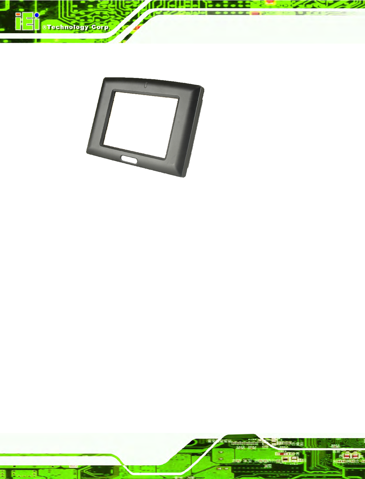
1.1 Overview
Figure 1-1: IOVU-570M
The IOVU-570M Panel PC comes with a 5.7" touch panel screen. It is powered by the
520 MHz Marvell XScale PXA270 processor and has 128 MB of SDRAM.
The IOVU-570M includes an SD card with Windows CE 5.0 installed. The package also
includes a software development kit and documentation to help easily customize the
operating system according to needs.
The IOVU-570M is an extremely low power Panel PC. The system is fanless, which allows
quiet and reliable operation
1.2 Benefits
Some of the IOVU-570M benefits include:
Customizable operating system to suit application needs.
Less downtime from overheating because there are not fans to fail
Cost savings with low power consumption
Easy installation with a wide range of input voltages supported
Can handle tough environments because of solid-state storage and IP64
protection of the front cover
IOVU-570M Panel PC
Page 3
1.3 Features
The IOVU-570M features are listed below:
520 MHz Marvell XScale PXA270 processor
128 MB of SDRAM
Two Ethernet ports
Two USB ports
One RS-232/422/485 serial communication connection
Two built-in speakers
4-wire resistive touch panel
12-36 VDC input
RoHS compliant
1.4 Technical Specifications
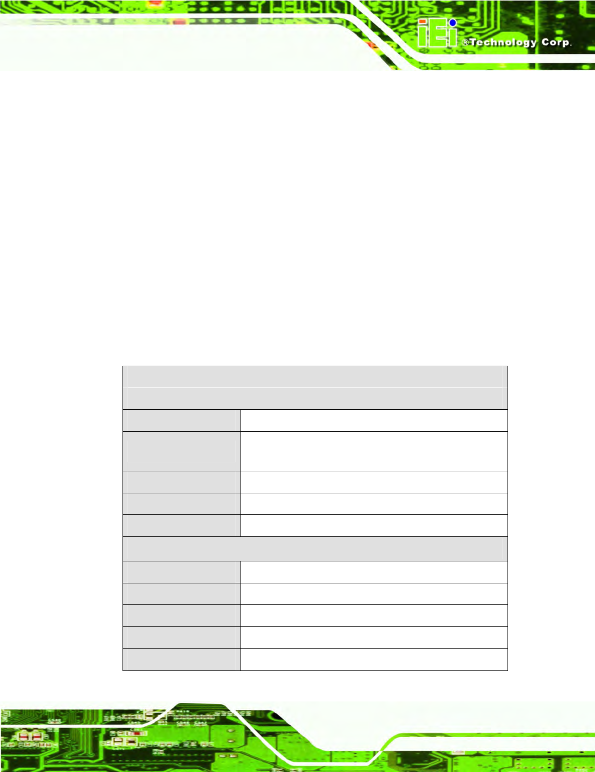
The IOVU-570M technical specifications are listed in Table 1-1.
Specifications
System
CPU 520 MHz Marvell XScale PXA270 processor
Memory 128 MB of SDRAM
1.0 GB SD card
Real-time Clock Battery backup RTC
Watchdog Timer Software programmable supports 1~255 sec. system reset
Reset Reset button
Display
Display Type TFT LCD screen
Display Size 5.7"
Resolution 640 x 480, 262,000
Brightness 400 cd/m2
Touch Panel 4-wired resistive touch panel
IOVU-570M Panel PC
Page 4
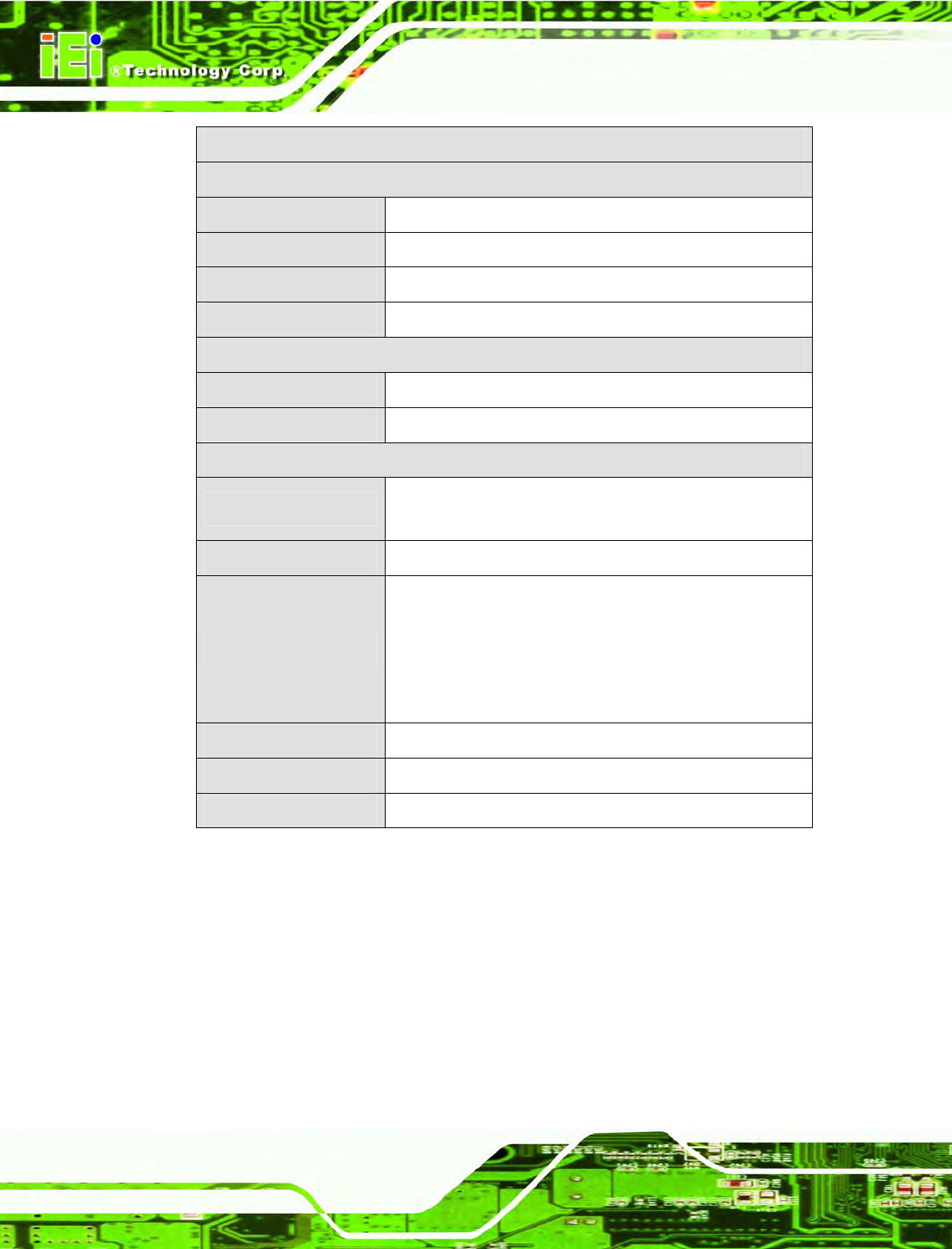
Specifications
I/O and Communications
Ethernet 2 x 10/100 Mb/s
Serial Ports 1 x RS-232/422/485
USB Interfaces 2 x USB host connectors
Audio 2 x 1.5 Watt speakers
Power
Power Supply 12-36 VDC
Power Consumption 8.5 W
Environmental and Mechanical
Operating Temperature
Minimum: -20ºC (-4°F)
Maximum: 60°C (140°F)
Humidity 5%RH to 90%RH (non-condensing)
Vibration
Operating Random Vibration Mode (MIL-STD-810F
514.5C-3)
1.Axes: 3 axs (Vertical / Transverse / Longitudinal).
2.10-500 Hz, 60min/axis.
3.Equivalent to Z:2.18 Grms X:1.6 Grms Y:1.96 Grms
Front Panel Color Pantone Black C
Physical Dimensions 180 mm x 135.8 mm x 46.7 mm
Ingress Protection IP 64 compliant front panel
Table 1-1: Technical Specifications
1.5 Certifications
All IOVU-570M series models comply with the following international standards:
RoHS
IP 64
For a more detailed description of these standards, please refer to Appendix A.
IOVU-570M Panel PC
Page 5
Chapter
2
2 Detailed Specifications
IOVU-570M Panel PC
Page 6
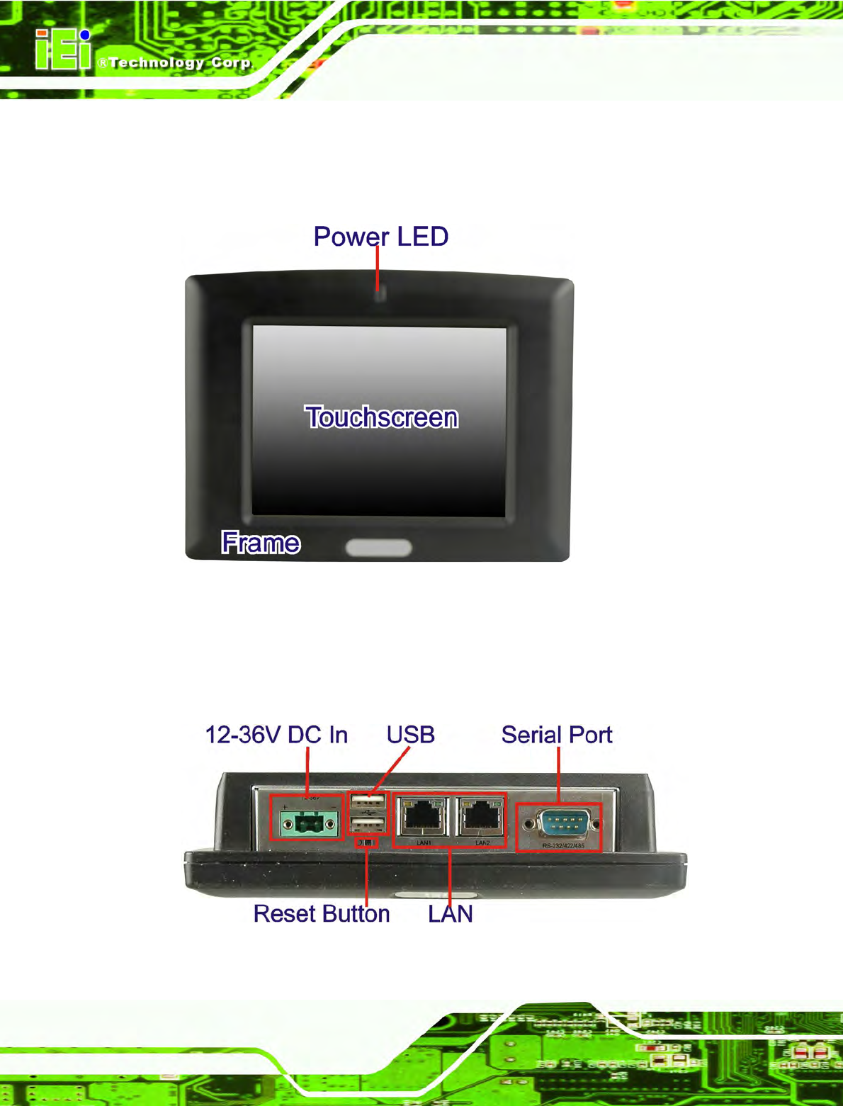
2.1 Front Panel
The IOVU-570M front panel (Figure 2-1) comprises a 5.7" TFT WVGA 16-bit color touch
screen LCD in an ABS+PC plastic frame.
Figure 2-1: Front Panel
2.2 Connector Panel
All external peripheral interface connectors are located on the bottom panel of the
IOVU-570M . The peripheral interface connectors are shown in Figure 2-2.
Figure 2-2: IOVU-570M Peripheral Connectors

IOVU-570M Panel PC
Page 7
External peripheral interface connectors on the IOVU-570M include:
1 x DC-IN bare wire terminal block
2 x RJ-45 LAN connectors
1 x RS-232/422/485 connector
2 x USB connectors
IOVU-570M Panel PC
Page 8
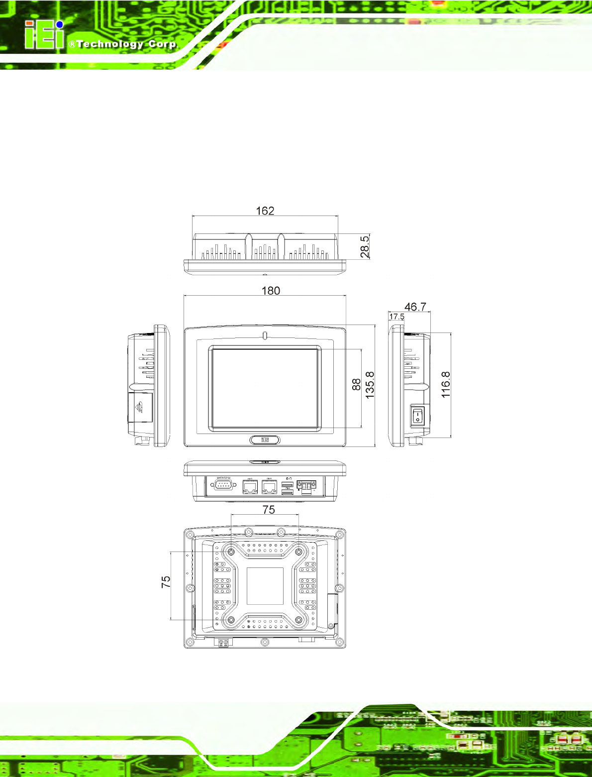
2.3 Dimensions
The physical dimensions of the IOVU-570M are shown in Figure 2-3 and listed below:
Width: 180 mm
Height: 135.8 mm
Depth: 46.7 mm
Figure 2-3: IOVU-570M Physical Dimensions (millimeters)

IOVU-570M Panel PC
Page 9
2.4 Power Supply
WARNING:
Whenever you need to remove a part for maintenance or upgrading,
switch off the power supply and unplug the power cord first.
And Risk of explosion if battery is replaced by an incorrect type.
Dispose of used batteries according to the instructions
The IOVU-570M has a terminal block connector on the bottom panel.
IOVU-570M Panel PC
Page 10
Chapter
3
3 Unpacking

IOVU-570M Panel PC
Page 11
3.1 Anti-static Precautions
WARNING:
Failure to take ESD precautions during installation may result in
permanent damage to the IOVU-570M and severe injury to the user.
Electrostatic discharge (ESD) can cause serious damage to electronic components,
including the IOVU-570M. Dry climates are especially susceptible to ESD. It is therefore
critical that whenever the IOVU-570M or any other electrical component is handled, the
following anti-static precautions are strictly adhered to.
Wear an anti-static wristband: Wearing a simple anti-static wristband can
help to prevent ESD from damaging the board.
Self-grounding: Before handling the board touch any grounded conducting
material. During the time the board is handled, frequently touch any
conducting materials that are connected to the ground.
Use an anti-static pad: When configuring the IOVU-570M, place it on an
antic-static pad. This reduces the possibility of ESD damaging the
IOVU-570M.
3.2 Unpacking Precautions
When the IOVU-570M is unpacked, please do the following:
Follow the anti-static precautions outlined in Section 3.1.
Make sure the packing box is facing upwards so the IOVU-570M does not fall
out of the box.
Make sure all the components shown in Section 3.3 are present.
IOVU-570M Panel PC
Page 12
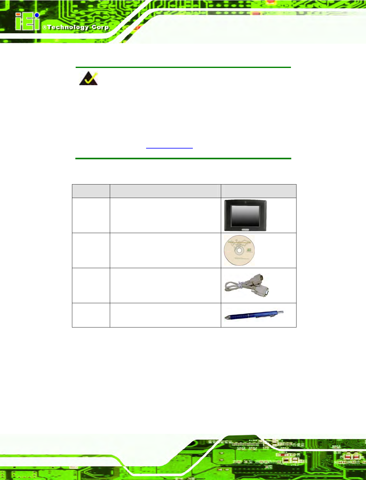
3.3 Unpacking Checklist
NOTE:
If some of the components listed in the checklist below are missing,
please do not proceed with the installation. Contact the IEI reseller or
vendor you purchased the IOVU-570M from or contact an IEI sales
representative directly. To contact an IEI sales representative, please
send an email to sales@iei.com.tw.
The IOVU-570M is shipped with the following components:
Quantity Item and Part Number Image
1 IOVU-570M
1 Utility CD including SDK, utilities, and
technical documentation
1 Null modem cable
1 Touch pen
Table 3-1: Package List Contents

IOVU-570M Panel PC
Page 13
Chapter
4
4 Installation

IOVU-570M Panel PC
Page 14
4.1 Installation Precautions
During installation, be aware of the precautions below:
Read the user manual: The user manual provides a complete description of
the IOVU-570M, installation instructions and configuration options.
DANGER! Disconnect Power: Power to the IOVU-570M must be
disconnected during the installation process, or before any attempt is made to
access the rear panel. Electric shock and personal injury might occur if the
rear panel of the IOVU-570M is opened while the power cord is still
connected to an electrical outlet.
Qualified Personnel: The IOVU-570M must be installed and operated only
by trained and qualified personnel. Maintenance, upgrades, or repairs may
only be carried out by qualified personnel who are familiar with the associated
dangers.
Air Circulation: Make sure there is sufficient air circulation when installing the
IOVU-570M. The IOVU-570M’s cooling vents must not be obstructed by any
objects. Blocking the vents can cause overheating of the IOVU-570M. Leave
at least 5 cm of clearance around the IOVU-570M to prevent overheating.
Grounding: The IOVU-570M should be properly grounded. The voltage feeds
must not be overloaded. Adjust the cabling and provide external overcharge
protection per the electrical values indicated on the label attached to the back
of the IOVU-570M.
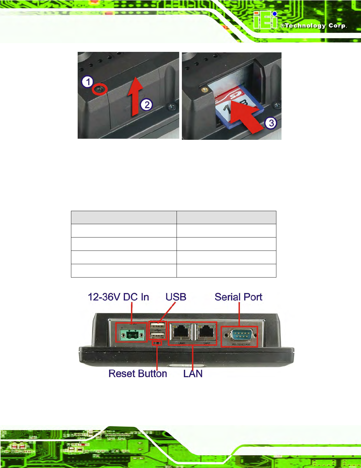
4.2 SD Card Installation
The IOVU-570M supports a single SD card. To install the SD card, follow the steps below.
Step 1: Undo the SD card cover screw.
Step 2: Slide open the SD card cover.
Step 3: Slide the SD card into the slot. Replace the SD card slot cover and screw.
Step 0:
IOVU-570M Panel PC
Page 15
Figure 4-1: SD Card Installation
4.3 External Peripheral Interface Connectors
Table 4-1 lists the external interface connectors on the IOVU-570M. Detailed descriptions
of the connectors can be found following the table.
Connector Type
12-36 V DC bare wire power terminal
Terminal Block
Ethernet connectors RJ-45 Jack connector
RS-232/422/485 Serial connector D-sub 9 Male connector
USB connectors Dual USB port
Table 4-1: External Interface Connectors
Figure 4-2: IOVU-570M Peripheral Connectors
IOVU-570M Panel PC
Page 16
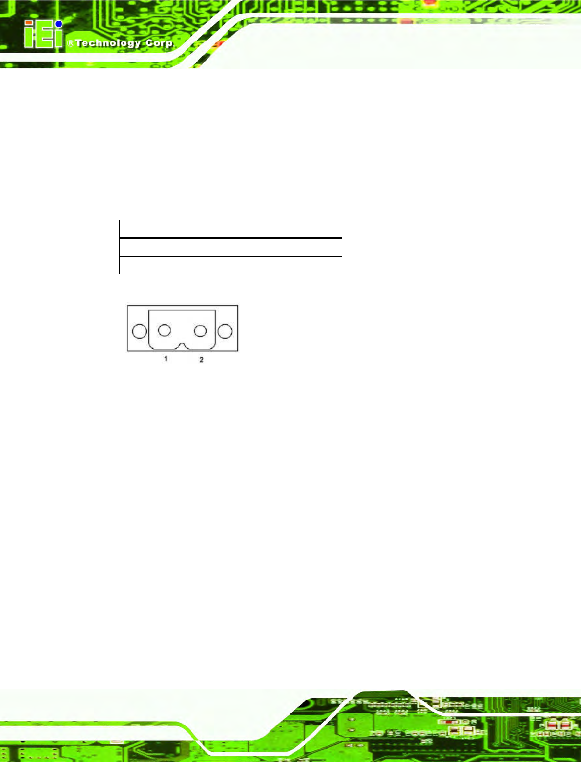
4.3.1 12 V~36 V DC Terminal Block
The power terminal block connects to a 12 V~36 V DC power source.
CN Label: 12-36 V
CN Type: Terminal block
CN Location:
See Figure 4-2
CN Pinouts: See Table 4-2 and Figure 4-3
Pin Description
1 12~36 V DC Power in
2 GND
Table 4-2: 12~36 V Power Connector Pinouts
Figure 4-3: Power Terminal Block
4.3.2 RS-232/422/485 Serial Port
This section outlines the usage and setup of the serial port on the rear I/O panel.
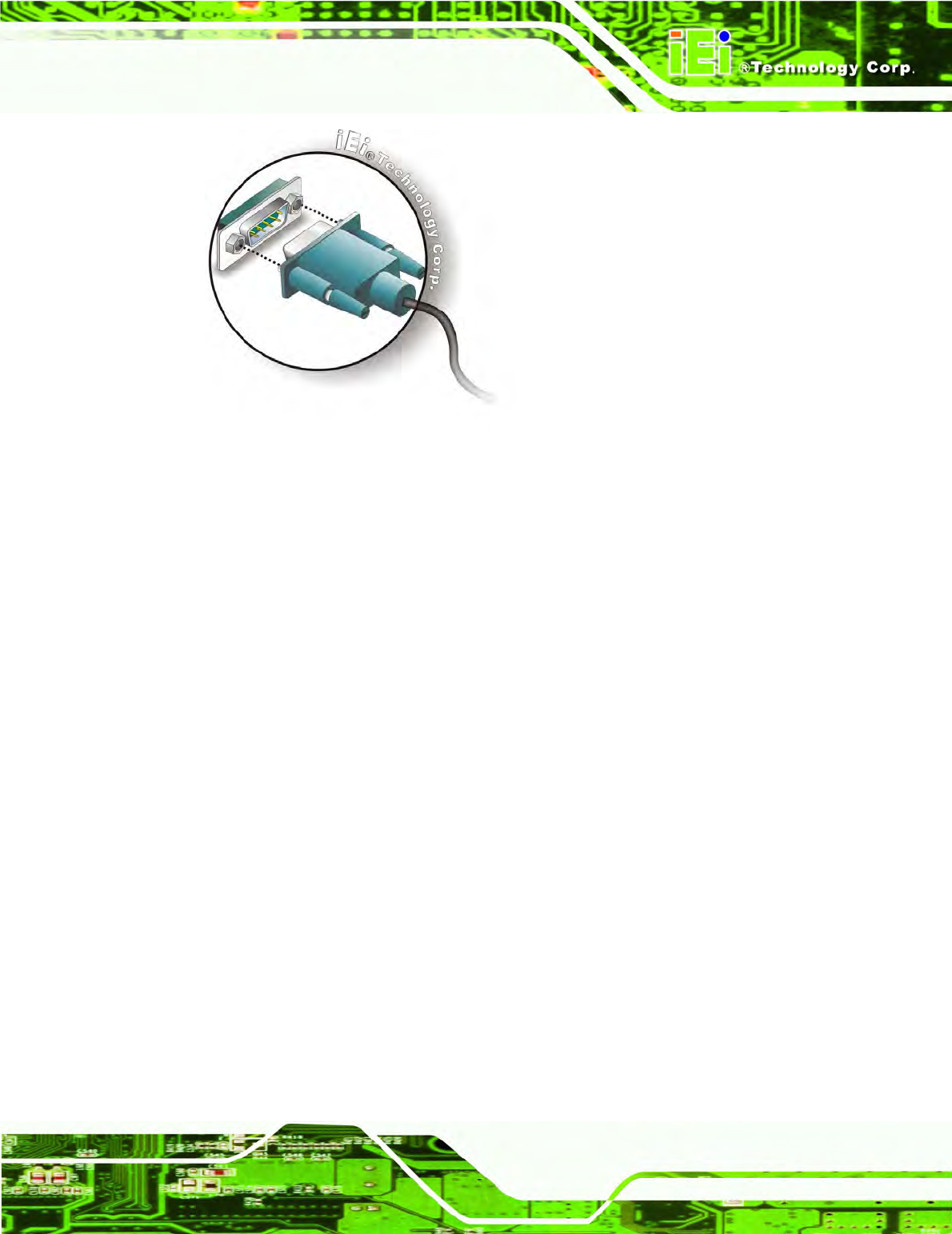
4.3.2.1 Connecting the Serial Port
The IOVU-570M has a single female DB-9 connector on the external peripheral interface
panel for a serial device. Follow the steps below to connect a serial device to the
IOVU-570M.
Step 1: Insert the serial connector. Insert the DB-9 connector of a serial device into
the DB-9 connector on the external peripheral interface. See Figure 4-4.
IOVU-570M Panel PC
Page 17
Figure 4-4: Serial Device Connector
Step 2: Secure the connector. Secure the serial device connector to the external
interface by tightening the two retention screws on either side of the connector.
Step 0:
4.3.2.2 RS-232/422/485 Selection
To select RS-232, RS-422, or RS-485 mode, please follow the directions below.
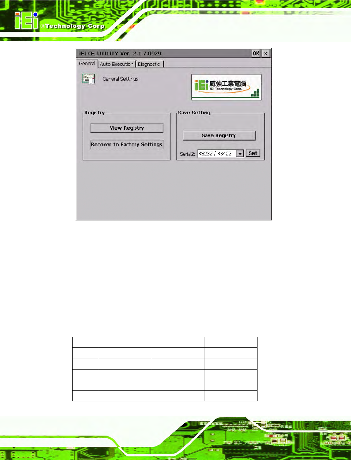
Step 1: Select "Start > Programs > IEI > IEI CEUTILITY.exe" to run IEI_CEUTILITY.exe
in the “SYSTEM” folder on the SD/CF card).
IOVU-570M Panel PC
Page 18
Figure 4-5: Serial Port Mode Setting
Step 2: Change serial port mode setting. Change the value in Figure 4-5 to the
desired mode setting.
Step 3: Click "Set"
Step 4: Click "Save Registry" to save the changes.
Step 0:
4.3.2.3 Pinouts
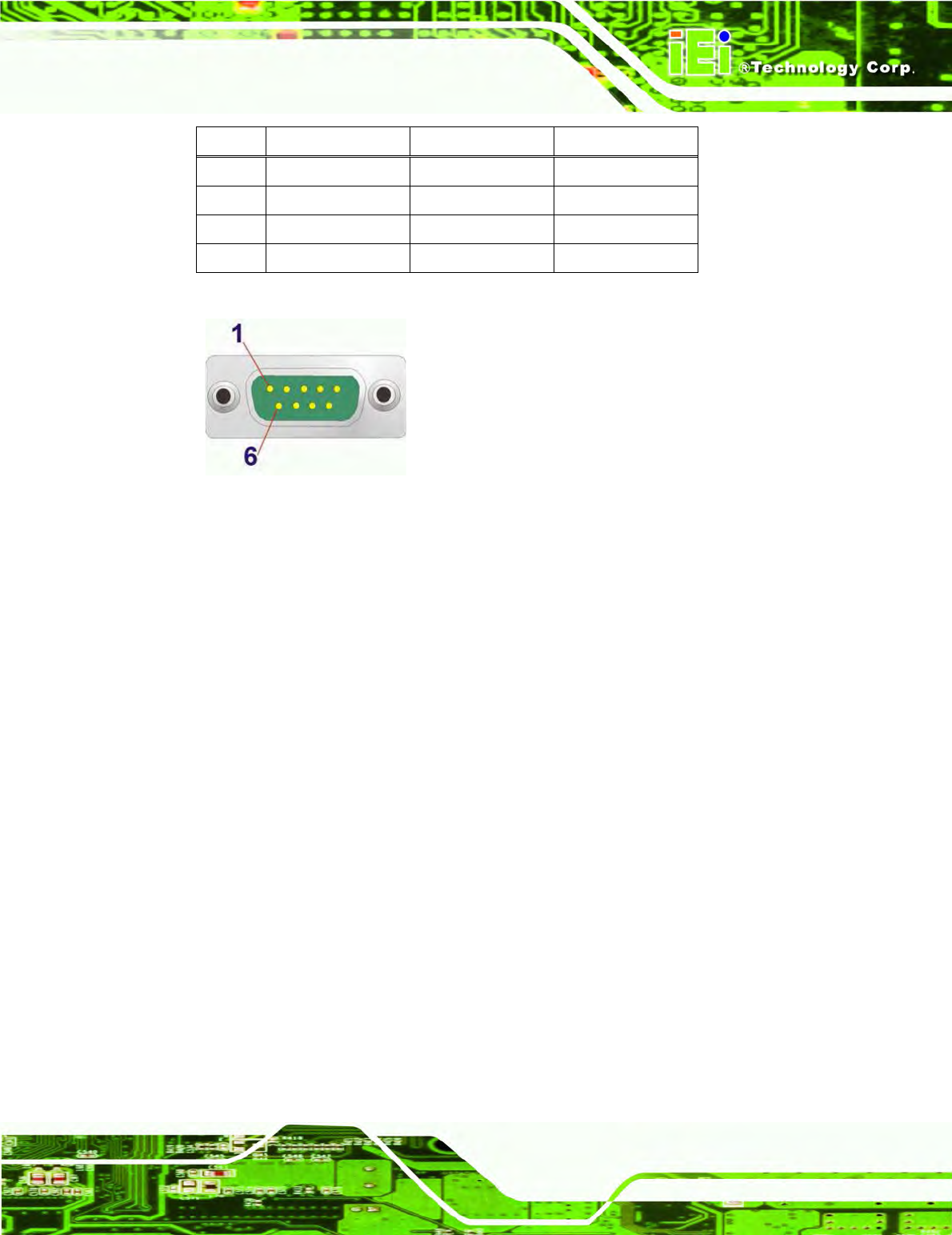
Serial port pinouts are shown below.
Pin RS-232 RS-422 RS-485
1 DCD RXD- DATA-
2 RX RXD+ DATA+
3 TX TXD-
4 DTR
5 GND GND GND
IOVU-570M Panel PC
Page 19
Pin RS-232 RS-422 RS-485
6 DSR
7 RTS TXD+
8 CTS
9 RI
Table 4-3: Serial Port Pinouts
Figure 4–6: Serial Port Pinouts
4.3.3 USB Connectors
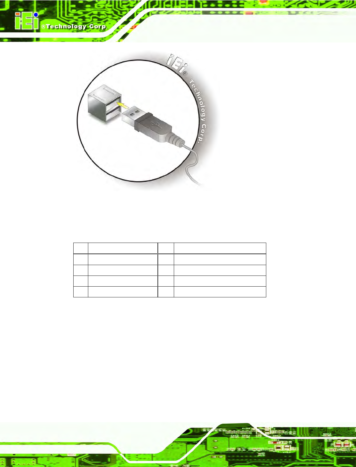
The external USB Series "A" receptacle connectors provide easier and quicker access to
external USB devices. Follow the steps below to connect USB devices to the IOVU-570M.
Step 1: Insert a USB Series "A" plug. Insert the USB Series "A" plug of a device into
the USB Series "A" receptacle on the external peripheral interface. See
Figure 4-7. Step 0:
IOVU-570M Panel PC
Page 20
Figure 4-7: USB Connector
USB devices connect directly to the USB connectors on the external peripheral connector
panel.
Pin
Description Pin
Description
1 VCC 5 VCC
2 D1- 6 D2-
3 D1+ 7 D2+
4 GND 8 GND
Table 4-4: USB Connector Pinouts
4.3.4 Ethernet Connector
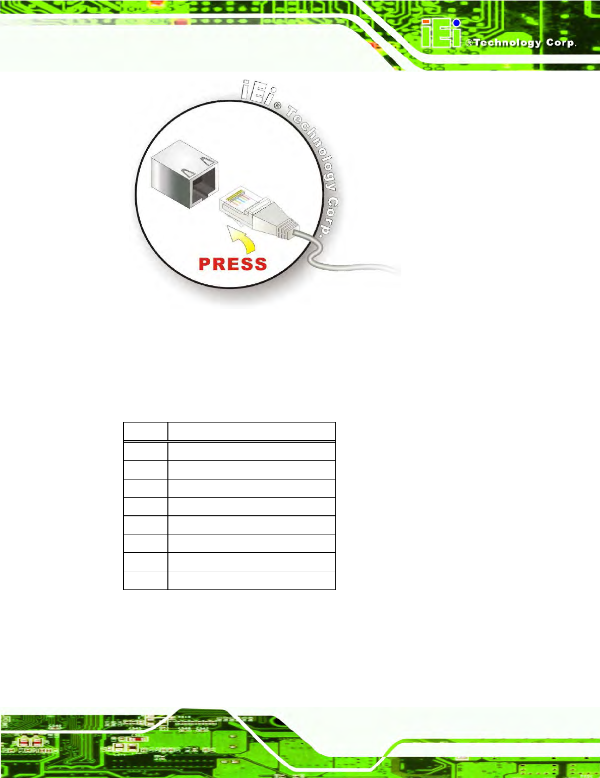
There are two external RJ-45 LAN connectors. The RJ-45 connectors enable connection
to an external network. To connect a LAN cable with an RJ-45 connector, please follow
the instructions below.
Step 1: Align the connectors. Align the RJ-45 connector on the LAN cable with one of
the RJ-45 connectors on the IOVU-570M. See Figure 4-8.
IOVU-570M Panel PC
Page 21
Figure 4-8: LAN Connection
Step 2: Insert the LAN cable RJ-45 connector. Once aligned, gently insert the LAN
cable RJ-45 connector into the on-board RJ-45 connector. Step 0:
The Ethernet connector pinouts are shown below.
PIN DESCRIPTION
1 TPT+
2 TPT-
3 TPR+
4 LAN_GND
5 LAN_GND
6 TPR-
7 LAN_GND
8 LAN_GND
Table 4-5: Ethernet Connector Pinouts
IOVU-570M Panel PC
Page 22
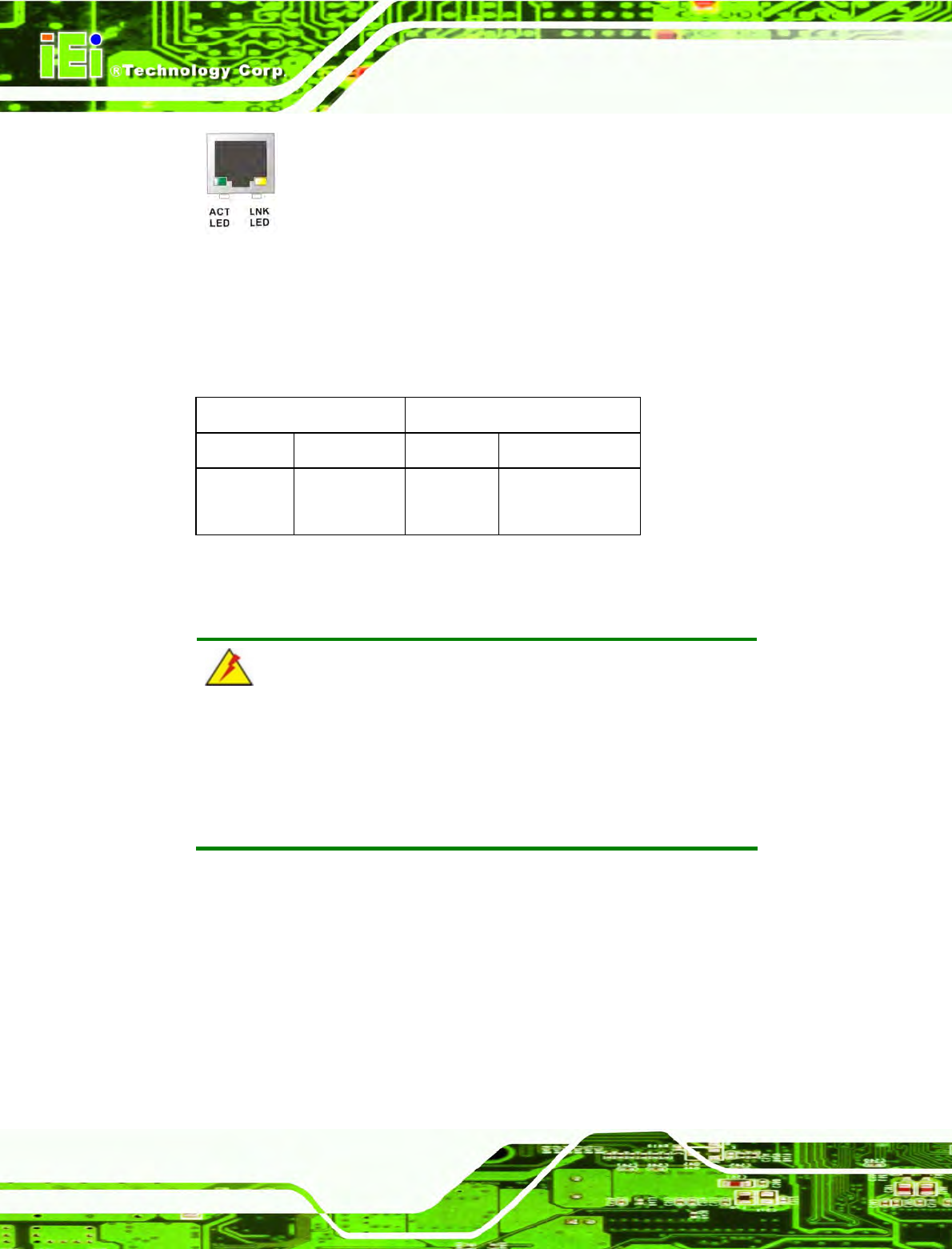
Figure 4-9: Ethernet Connector
The RJ-45 Ethernet connector has two status LEDs, one green and one yellow. The green
LED indicates activity on the port and the yellow LED indicates the port is linked
(Table 4-6).
SPEED LED LINK LED
Status Description Status Description
GREEN ON: 100 MB
OFF: 10 MB
YELLOW ON: Linked
Flashing: Activity
Table 4-6: Ethernet Connector LEDs
4.4 Mounting the System
WARNING!
When mounting the flat panel PC onto an arm, onto the wall or onto a
panel, it is better to have more than one person to help with the
installation to make sure the panel PC does not fall down and get
damaged.
Three methods of mounting the IOVU-570M are listed below.
Wall mounting
The mounting methods are described below.
4.4.1 Wall Mounting
To mount the IOVU-570M onto the wall, please follow the steps below.
IOVU-570M Panel PC
Page 23
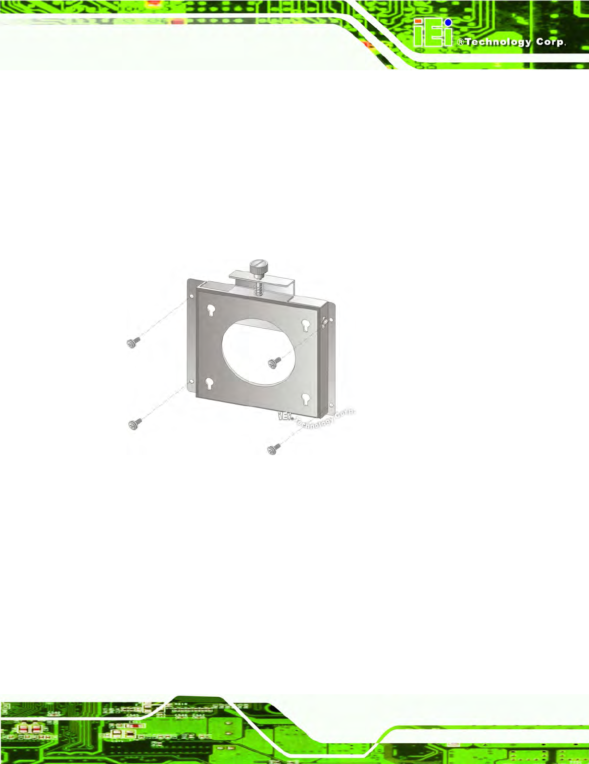
Step 1: Select the location on the wall for the wall-mounting bracket.
Step 2: Carefully mark the locations of the four screw holes in the bracket on the wall.
Step 3: Drill four pilot holes at the marked locations on the wall for the bracket retention
screws.
Step 4: Align the wall-mounting bracket screw holes with the pilot holes.
Step 5: Secure the mounting-bracket to the wall by inserting the retention screws into
the four pilot holes and tightening them (Figure 4-10).
Figure 4-10: Wall-mounting Bracket
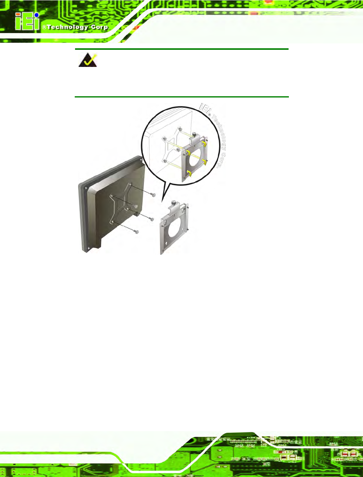
Step 6: Insert the four monitor mounting screws provided in the wall mounting kit into the
four screw holes on the real panel of the IOVU-570M and tighten until the screw
shank is secured against the rear panel (Figure 4-11).
Step 7: Align the mounting screws on the monitor rear panel with the mounting holes on
the bracket.
Step 8: Carefully insert the screws through the holes and gently pull the monitor
downwards until the monitor rests securely in the slotted holes (Figure 4-11).
Ensure that all four of the mounting screws fit snuggly into their respective
slotted holes.
IOVU-570M Panel PC
Page 24
NOTE:
In the diagram below the bracket is already installed on the wall.
Figure 4-11: Chassis Support Screws
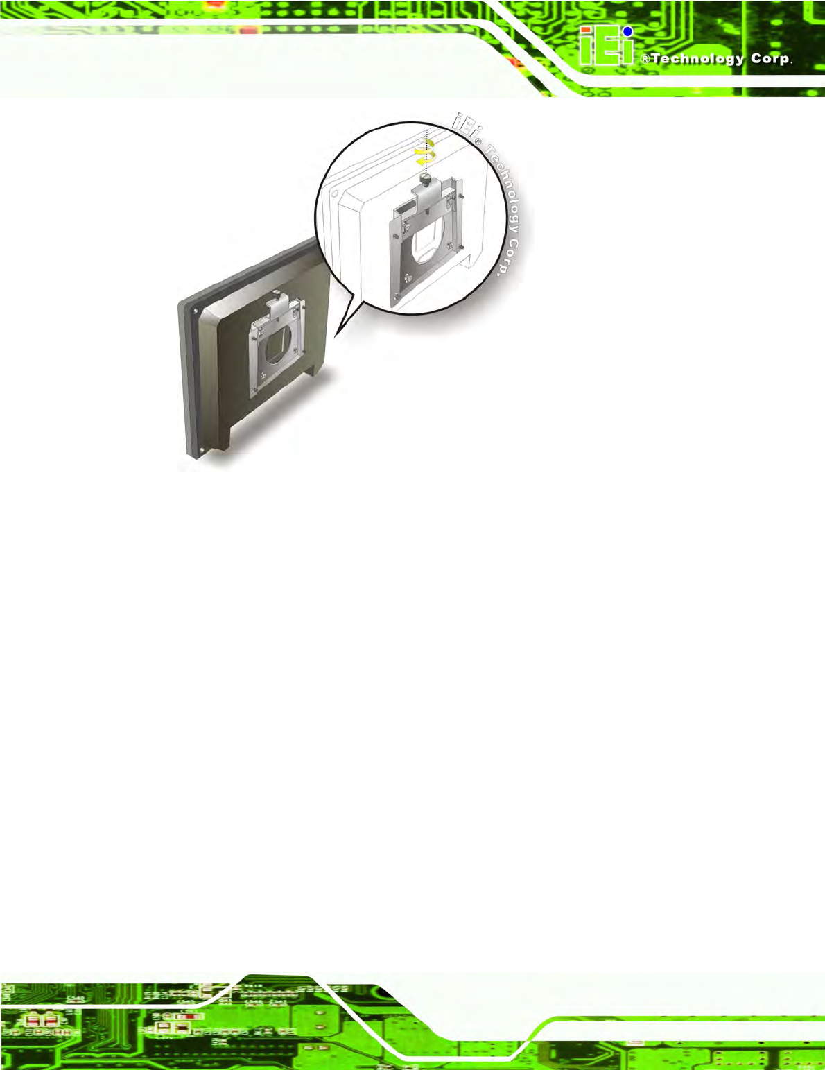
Step 9: Secure the panel PC by fastening the retention screw of the wall-mounting
bracket. (Figure 4-12). Step 0:
IOVU-570M Panel PC
Page 25
Figure 4-12: Secure the IOVU-570M
4.5 Software
The IOVU-570M comes with a pre-installed Windows CE 5.0 or Linux 2.6.x operating
system and a rich software application development kit. For information about configuring
the operating system, adding remote management tools or additional software and drivers,
refer to the user manuals on IEI IOVU Utility CD that came with the IOVU-570M. The
IOVU includes the following software:
Standard Windows® CE5.0 professional version license.
Optional Board Support Package (BSP) for customers to customize their own
OS image.
Attached Software Development Kit (SDK) for embedded Visual C++ to
program Windows CE application.
Built-in .NET Compact Framework support with related SDK
Thin Client Technology, Microsoft RDP (Remote Desktop Protocol), to enable
IOVU-570M to access Microsoft Windows® based applications installed on
Microsoft Terminal Service server.
Free pre-installed utilities for configuring and diagnosing your IOVU-570M.
IOVU-570M Panel PC
Page 26
Free remote management tools installed in laptop for remotely configuring,
monitoring, and managing your IOVU-570M.
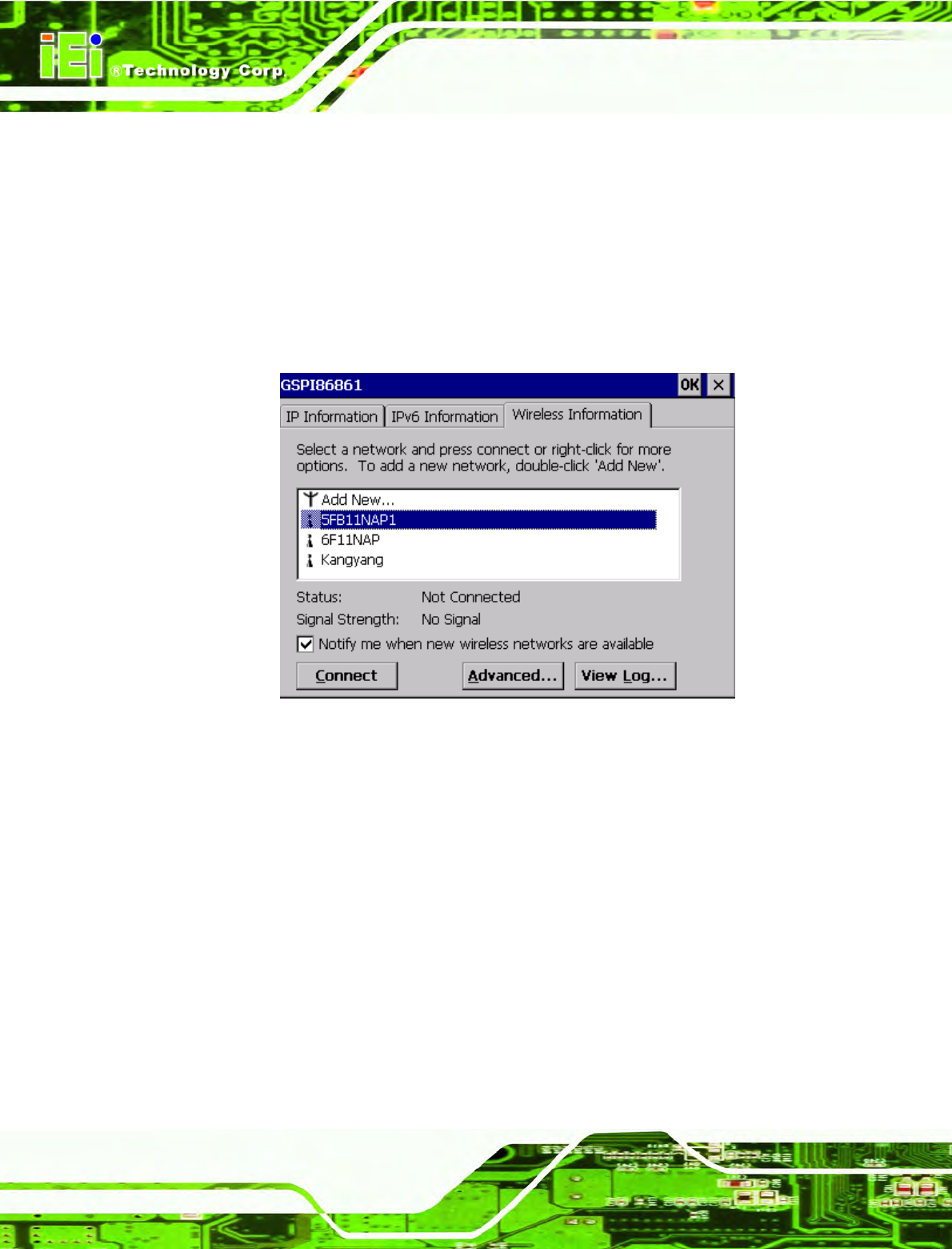
4.5.1 Wireless AP
To select Wireless AP, please follow the instructions below.
Step 1: When turn on the power, Wireless AP start to search wireless base stations
around as shown below. (Figure 4-13).
Figure 4-13: Wireless AP
Step 2: Select your Internet connection and click Connect.
Step 3: The Wireless Network Properties screen appears next. (Figure 4-14).
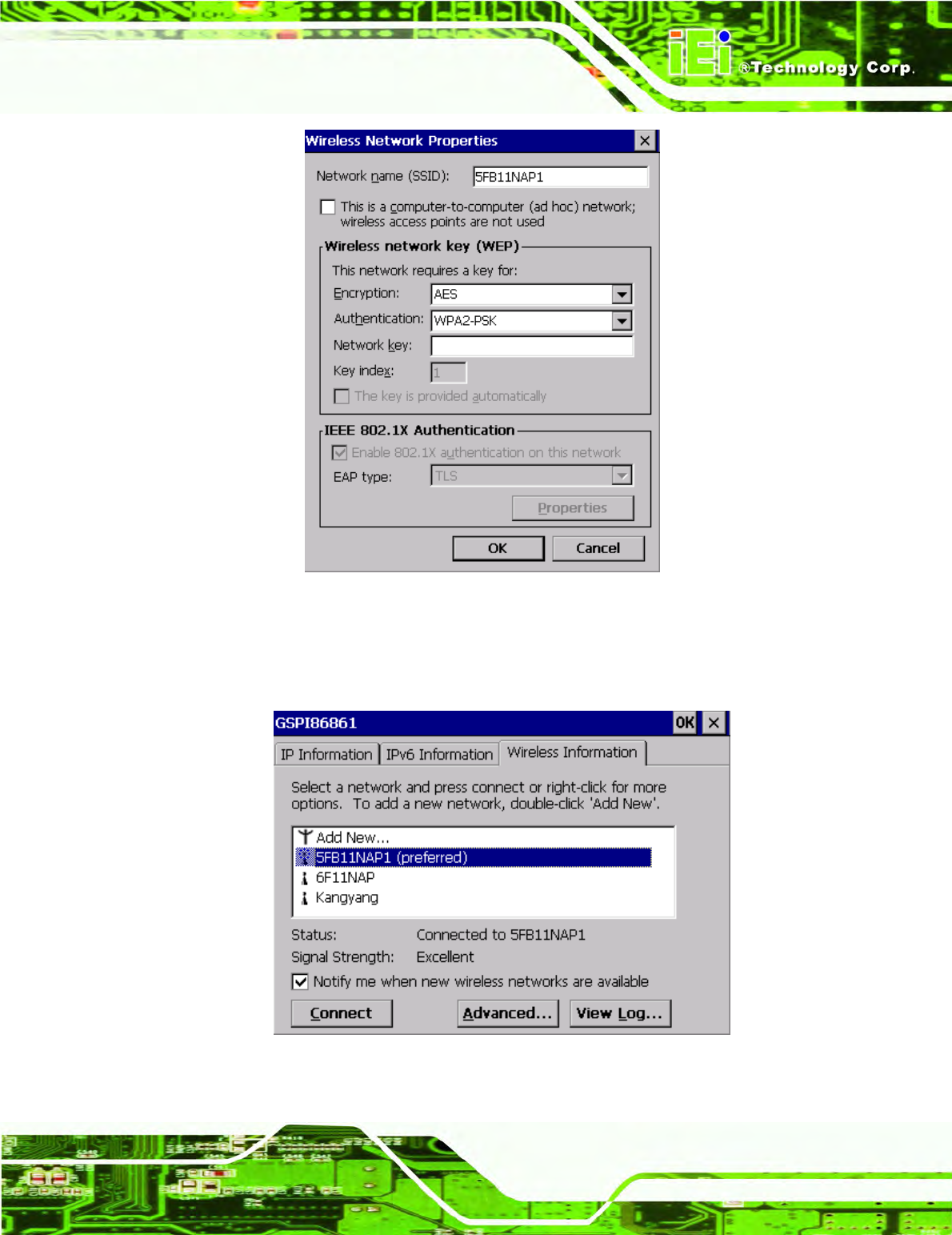
IOVU-570M Panel PC
Page 27
Figure 4-14: Wireless Network Properties
Step 4: You must input the password into the Network key. Click OK. The soft AP
configuration is finished. (Figure 4-15).
Figure 4-15: Wireless AP Connected
IOVU-570M Panel PC
Page 28
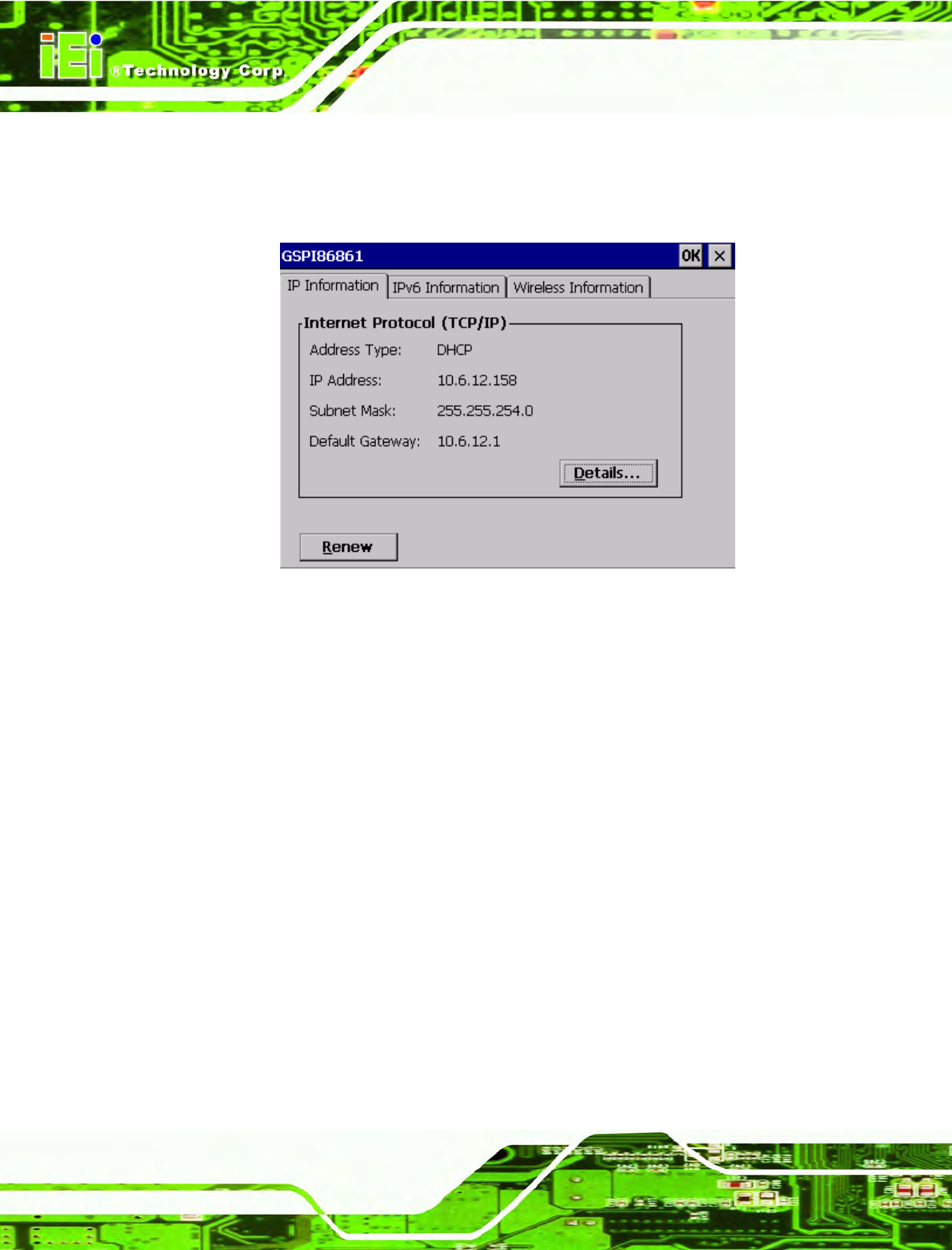
Step 5: Click the IP Information button to view the information of the Wireless AP Solo.If
the server function is enabled on the AP. You can automatically get the IP
address, subnet mask. (Figure 4-16).
Figure 4-16: IP Information

IOVU-570M Panel PC
Page 29
Appendix
A
A Certifications

IOVU-570M Panel PC
Page 30
A.1 RoHS Compliant
All models in the IOVU series comply with the Restriction of Hazardous Materials (RoHS)
Directive. This means that all components used to build the industrial workstations and the
workstation itself are RoHS compliant.
The RoHS Directive bans the placing on the EU market of new electrical and electronic
equipment containing more than agreed levels of lead, cadmium, mercury, hexavalent
chromium, polybrominated biphenyl (PBB) and polybrominated diphenyl ether (PBDE)
flame retardants.
A.2 IP 64 Compliant Front Panel
The front panels on all models in the IOVU series have an ingress protection rating (IP) of
64, IP 64 or greater. The front panels are protected from dust particles and splashed
water.

IOVU-570M Panel PC
Page 31
Appendix
B
B Safety Precautions
IOVU-570M Panel PC
Page 32
B.1 Safety Precautions
WARNING:
The precautions outlined in this appendix should be strictly followed.
Failure to follow these precautions may result in permanent damage to
the IOVU-570M.
Please follow the safety precautions outlined in the sections that follow:
B.1.1 General Safety Precautions
Please ensure the following safety precautions are adhered to at all times.
Make sure the power is turned off and the power cord is disconnected
whenever the IOVU-570M is being installed, moved or modified.
Do not apply voltage levels that exceed the specified voltage range.
Doing so may cause fire and/or an electrical shock.
Electric shocks can occur if the IOVU-570M chassis is opened when the
IOVU-570M is running.
Do not drop or insert any objects into the ventilation openings of the
IOVU-570M.
If considerable amounts of dust, water, or fluids enter the IOVU-570M,
turn off the power supply immediately, unplug the power cord, and contact the
IOVU-570M vendor.
DO NOT:
o Drop the IOVU-570M against a hard surface.
o Strike or exert excessive force onto the LCD panel.
o Touch any of the LCD panels with a sharp object
o In a site where the ambient temperature exceeds the rated temperature
IOVU-570M Panel PC
Page 33
B.1.2 Anti-static Precautions
WARNING:
Failure to take ESD precautions during the installation of the
IOVU-570M may result in permanent damage to the IOVU-570M and
severe injury to the user.
Electrostatic discharge (ESD) can cause serious damage to electronic components,
including the IOVU-570M. Dry climates are especially susceptible to ESD. It is therefore
critical that whenever the IOVU-570M is opened and any of the electrical components are
handled, the following anti-static precautions are strictly adhered to.
Wear an anti-static wristband: Wearing a simple anti-static wristband can
help to prevent ESD from damaging any electrical component.
Self-grounding: Before handling any electrical component, touch any
grounded conducting material. During the time the electrical component is
handled, frequently touch any conducting materials that are connected to the
ground.
Use an anti-static pad: When configuring or working with an electrical
component, place it on an antic-static pad. This reduces the possibility of ESD
damage.
Only handle the edges of the electrical component: When handling the
electrical component, hold the electrical component by its edges.
B.2 Maintenance and Cleaning Precautions
When maintaining or cleaning the IOVU-570M, please follow the guidelines below.
B.2.1 Maintenance and Cleaning
Prior to cleaning any part or component of the IOVU-570M, please read the details below.
Except for the LCD panel, never spray or squirt liquids directly onto any other
components. To clean the LCD panel, gently wipe it with a piece of soft dry
cloth or a slightly moistened cloth.
IOVU-570M Panel PC
Page 34
The interior of the IOVU-570M does not require cleaning. Keep fluids away
from the IOVU-570M interior.
Be cautious of all small removable components when vacuuming the
IOVU-570M.
Turn the IOVU-570M off before cleaning the IOVU-570M.
Never drop any objects or liquids through the openings of the IOVU-570M.
Be cautious of any possible allergic reactions to solvents or chemicals used
when cleaning the IOVU-570M.
Avoid eating, drinking and smoking within vicinity of the IOVU-570M.
B.2.2 Cleaning Tools
Some components in the IOVU-570M may only be cleaned using a product specifically
designed for the purpose. In such case, the product will be explicitly mentioned in the
cleaning tips. Below is a list of items to use when cleaning the IOVU-570M.
Cloth – Although paper towels or tissues can be used, a soft, clean piece of
cloth is recommended when cleaning the IOVU-570M.
Water or rubbing alcohol – A cloth moistened with water or rubbing alcohol
can be used to clean the IOVU-570M.
Using solvents – The use of solvents is not recommended when cleaning the
IOVU-570M as they may damage the plastic parts.
Vacuum cleaner – Using a vacuum specifically designed for computers is
one of the best methods of cleaning the IOVU-570M. Dust and dirt can restrict
the airflow in the IOVU-570M and cause its circuitry to corrode.
Cotton swabs - Cotton swaps moistened with rubbing alcohol or water are
excellent tools for wiping hard to reach areas.
Foam swabs - Whenever possible, it is best to use lint free swabs such as
foam swabs for cleaning.
IOVU-570M Panel PC
Page 35
B.3 FCC Precautions
WARNING:
This equipment has been tested and found to comply with the limits for a Class A
digital device, pursuant to Part 15 of the FCC Rules. These limits are designed to
provide reasonable protection against harmful interference in a residential
installation. This equipment generates, uses and can radiate radio frequency
energy and, if not installed and used in accordance with the instructions, may
cause harmful interference to radio communications. However, there is no
guarantee that interference will not occur in a particular installation. If this
equipment does cause harmful interference to radio or television reception, which
can be determined by turning the equipment off and on, the user is encouraged to
try to correct the interference by one or more of the following measures:
Reorient or relocate the receiving antenna.
Increase the separation between the equipment and receiver.
Connect the equipment into an outlet on a circuit different from that to which
the receiver is connected.
Consult the dealer or an experienced radio/TV technician for help.
FCC Caution: Any changes or modifications not expressly approved by the party
responsible for compliance could void the user's authority to operate this
equipment.
This device and its antenna(s) must not be co-located or operating in conjunction
with any other antenna or transmitter.
IMPORTANT NOTE: FCC Radiation Exposure Statement: This equipment complies
with FCC radiation exposure limits set forth for an uncontrolled environment. This
equipment should be installed and operated with minimum distance 20cm between
the radiator & your body.
For product available in the USA/Canada market, only channel 1~11 can be
operated. Selection of other channels is not possible.
This device complies with Part 15 of the FCC Rules. Operation is subject to the
following two conditions: (1) This device may not cause harmful interference, and
(2) this device must accept any interference received, including interference that
may cause undesired operation.
IOVU-570M Panel PC
Page 36
Appendix
C
C Hazardous Materials
Disclosure

IOVU-570M Panel PC
Page 37
C.1 Hazardous Materials Disclosure Table for IPB Products
Certified as RoHS Compliant Under 2002/95/EC Without
Mercury
The details provided in this appendix are to ensure that the product is compliant with the
Peoples Republic of China (China) RoHS standards. The table below acknowledges the
presences of small quantities of certain materials in the product, and is applicable to China
RoHS only.
A label will be placed on each product to indicate the estimated “Environmentally Friendly
Use Period” (EFUP). This is an estimate of the number of years that these substances
would “not leak out or undergo abrupt change.” This product may contain replaceable
sub-assemblies/components which have a shorter EFUP such as batteries and lamps.
These components will be separately marked.
Please refer to the table on the next page.

IOVU-570M Panel PC
Page 38
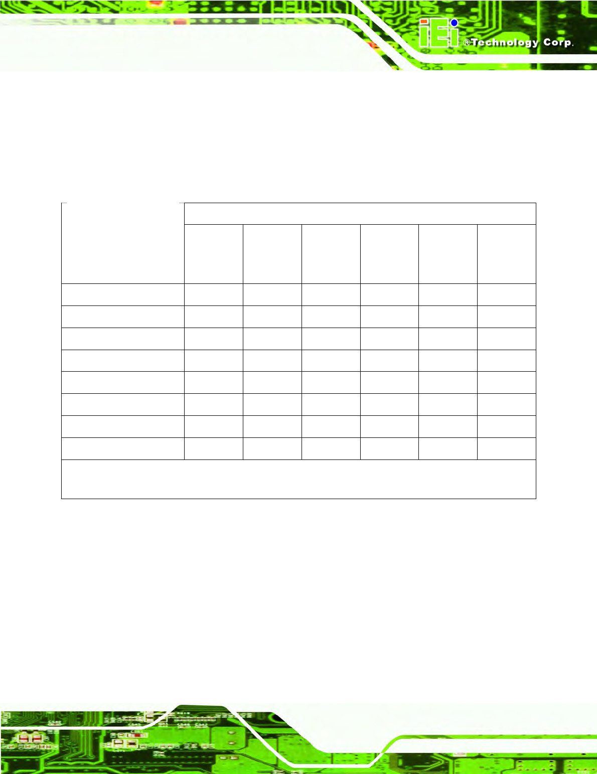
Toxic or Hazardous Substances and Elements Part Name
Lead
(Pb)
Mercury
(Hg)
Cadmium
(Cd)
Hexavalent
Chromium
(CR(VI))
Polybrominated
Biphenyls
(PBB)
Polybrominated
Diphenyl
Ethers
(PBDE)
Housing X O O O O X
Display X O O O O X
Printed Circuit
Board
X O O O O X
Metal
Fasteners
X O O O O O
Cable
Assembly
X O O O O X
Fan Assembly
X O O O O X
Power Supply
Assemblies
X O O O O X
Battery O O O O O O
O: This toxic or hazardous substance is contained in all of the homogeneous materials for the part is
below the limit requirement in SJ/T11363-2006
X: This toxic or hazardous substance is contained in at least one of the homogeneous materials for
this part is above the limit requirement in SJ/T11363-2006
IOVU-570M Panel PC
Page 39
此附件旨在确保本产品符合中国 RoHS 标准。以下表格标示此产品中某有毒物质的含量符
合中国 RoHS 标准规定的限量要求。
本产品上会附有”环境友好使用期限”的标签,此期限是估算这些物质”不会有泄漏或突变”的
年限。本产品可能包含有较短的环境友好使用期限的可替换元件,像是电池或灯管,这些元
件将会单独标示出来。
有毒有害物质或元素
有毒有害物质或元素有毒有害物质或元素
有毒有害物质或元素 部件名称
部件名称部件名称
部件名称
铅
铅铅
铅
(Pb)
汞
汞汞
汞
(Hg)
镉
镉镉
镉
(Cd)
六价铬
六价铬六价铬
六价铬
(CR(VI))
多溴联苯
多溴联苯多溴联苯
多溴联苯
(PBB)
多溴二苯
多溴二苯多溴二苯
多溴二苯
醚
醚醚
醚
(PBDE)
壳体
壳体壳体
壳体 X O O O O X
显示
显示显示
显示 X O O O O X
印刷电路板
印刷电路板印刷电路板
印刷电路板 X O O O O X
金属螺帽
金属螺帽金属螺帽
金属螺帽 X O O O O O
电缆组装
电缆组装电缆组装
电缆组装 X O O O O X
风扇组装
风扇组装风扇组装
风扇组装 X O O O O X
电力供应组装
电力供应组装电力供应组装
电力供应组装 X O O O O X
电池
电池电池
电池 O O O O O O
O: 表示该有毒有害物质在该部件所有物质材料中的含量均在 SJ/T11363-2006 标准规定的限量要求以下。
X: 表示该有毒有害物质至少在该部件的某一均质材料中的含量超出 SJ/T11363-2006 标准规定的限量要求。