IEI Integration IRFR-300 EMBEDDED SYSTEM User Manual AVL 2000PLUS UMN v1 00 2011 06 21 statement 20cm
IEI Integration Corp. EMBEDDED SYSTEM AVL 2000PLUS UMN v1 00 2011 06 21 statement 20cm
UserMan_RFHIRFR-300_rev. 1
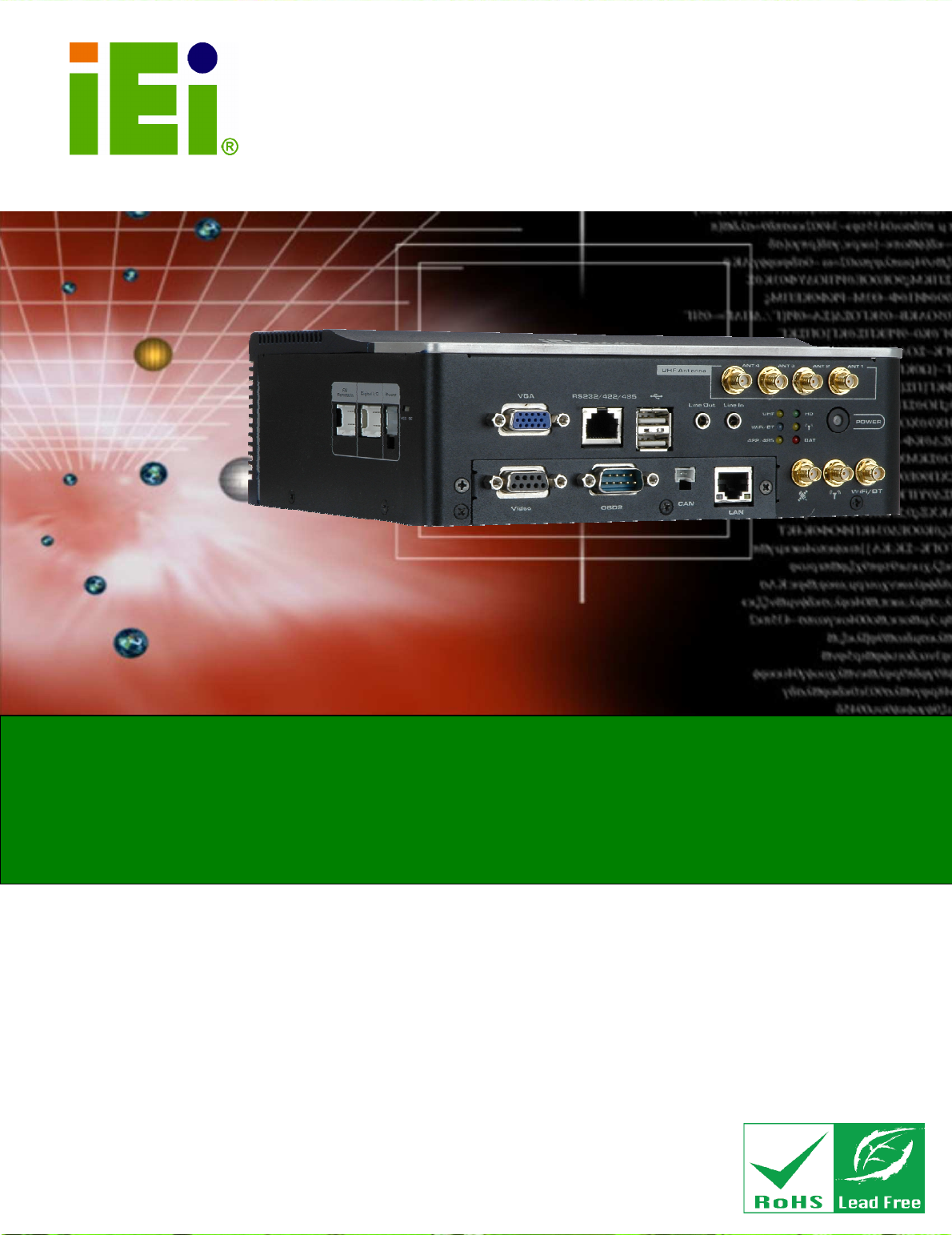
AVL-2000PLUS Auto Data Server
Page 1
IEI Technology Corp.
User Manual
MODEL:
AVL-2000PLUS
Auto Data Server
with
Intel® Atom™
CPU
,
Gigabit Ethernet, OBD-II, USB, GPS, Wi-Fi, Bluetooth,
Video Capture, Audio, RS-232/422/485, RoHS Compliant
Rev. 1.00 – 28 June, 2011
AVL-2000PLUS Auto Data Server
Page 2
Revision
Date Version
Changes
28 June, 2011 1.00 Initial release

AVL-2000PLUS Auto Data Server
Page 3
Copyright
COPYRIGHT NOTICE
The information in this document is subject to change without prior notice in order to
improve reliability, design and function and does not represent a commitment on the part
of the manufacturer.
In no event will the manufacturer be liable for direct, indirect, special, incidental, or
consequential damages arising out of the use or inability to use the product or
documentation, even if advised of the possibility of such damages.
This document contains proprietary information protected by copyright. All rights are
reserved. No part of this manual may be reproduced by any mechanical, electronic, or
other means in any form without prior written permission of the manufacturer.
TRADEMARKS
All registered trademarks and product names mentioned herein are used for identification
purposes only and may be trademarks and/or registered trademarks of their respective
owners.
AVL-2000PLUS Auto Data Server
Page 4
Table of Contents
1 INTRODUCTION.......................................................................................................... 8
1.1
O
VERVIEW
.................................................................................................................. 9
1.2
F
EATURES
................................................................................................................... 9
1.3
F
RONT
P
ANEL
........................................................................................................... 10
1.3.1 LED Indicators..................................................................................................11
1.4
R
EAR
P
ANEL
..............................................................................................................11
1.5
R
IGHT
P
ANEL
............................................................................................................ 12
1.6
L
EFT
P
ANEL
.............................................................................................................. 12
1.7
S
YSTEM
S
PECIFICATIONS
.......................................................................................... 13
1.8
D
IMENSIONS
............................................................................................................. 15
2 UNPACKING ............................................................................................................... 16
3 INSTALLATION ......................................................................................................... 20
3.1
A
NTI
-
STATIC
P
RECAUTIONS
...................................................................................... 21
3.2
I
NSTALLATION
P
RECAUTIONS
................................................................................... 21
3.3
I
NSTALLATION AND
C
ONFIGURATION
S
TEPS
............................................................. 22
3.4
SIM
C
ARD AND
SD
C
ARD
I
NSTALLATION
................................................................ 22
3.5
M
OUNTING THE
S
YSTEM
.......................................................................................... 23
3.6
I/O
I
NTERFACE
C
ONNECTORS
................................................................................... 24
3.6.1 CAN Bus Connection ....................................................................................... 24
3.6.2 Digital I/O Connection .................................................................................... 24
3.6.3 LAN Connection............................................................................................... 25
3.6.4 OBD-II Connector ........................................................................................... 26
3.6.5 Power Input Connection .................................................................................. 27
3.6.6 Remote Control Connection............................................................................. 28
3.6.7 Serial Device Connection ................................................................................ 28
3.6.7.1 COM1 Pinouts .......................................................................................... 29
3.6.8 USB Device Connection................................................................................... 30
3.6.9 Video Capture Connection ............................................................................... 30
3.6.10 VGA Monitor Connection .............................................................................. 31

AVL-2000PLUS Auto Data Server
Page 5
3.7
P
OWER
-O
N
P
ROCEDURE
........................................................ 錯
錯錯
錯誤
誤誤
誤!
尚未定義書籤
尚未定義書籤尚未定義書籤
尚未定義書籤。
。。
。
3.7.1 Installation Checklist ....................................................
錯誤
錯誤錯誤
錯誤
!
尚未定義書籤
尚未定義書籤尚未定義書籤
尚未定義書籤。
。。
。
3.7.2 Power-on Procedure .....................................................
錯誤
錯誤錯誤
錯誤
!
尚未定義書籤
尚未定義書籤尚未定義書籤
尚未定義書籤。
。。
。
3.7.3 Power State ...................................................................
錯誤
錯誤錯誤
錯誤
!
尚未定義書籤
尚未定義書籤尚未定義書籤
尚未定義書籤。
。。
。
3.8
S
YSTEM
M
AINTENANCE
........................................................................................... 32
AVL-2000PLUS Auto Data Server
Page 6
List of Figures
Figure 1-1: AVL-2000PLUS Auto Data Server ..........................................................................9
Figure 1-2: Front Panel ...........................................................................................................10
Figure 1-3: LED Indicators......................................................................................................11
Figure 1-4: Rear View..............................................................................................................11
Figure 1-5: Right Panel ...........................................................................................................12
Figure 1-6: Left Panel..............................................................................................................12
Figure 1-7: Dimensions (unit: mm).........................................................................................15
Figure 3-1: Panel Retention Screw .........................................................................................22
Figure 3-2: Slot Locations.......................................................................................................23
Figure 3-3: VESA Mounting Bracket.......................................................................................23
Figure 3-4: CAN Bus Connector Pinouts................................................................................24
Figure 3-5: Digital I/O Connector Pinouts Location...............................................................24
Figure 3-6: LAN Connection ...................................................................................................25
Figure 3-7: OBD-II Cable and J1939/FMS Cable.....................................................................26
Figure 3-8: OBD-II Connector Pinouts Location ....................................................................26
Figure 3-9: OBD-II Connector Pinouts....................................................................................27
Figure 3-10: J1939/FMS Connector Pinouts...........................................................................27
Figure 3-11: Power Input Connector ......................................................................................27
Figure 3-12: Power Cable..........................................................................錯誤! 尚未定義書籤。
Figure 3-13: Remote Control Connector Pinouts Location ...................................................28
Figure 3-14: Serial Device Connector.....................................................................................29
Figure 3-15: USB Device Connection .....................................................................................30
Figure 3-16: Video Capture Cable...........................................................................................31
Figure 3-17: Video Connector Pinouts Location....................................................................31
Figure 3-18: VGA Connector...................................................................................................32
AVL-2000PLUS Auto Data Server
Page 7
List of Tables
Table 1-1: Technical Specifications........................................................................................14
Table 2-1: Packing List............................................................................................................18
Table 2-2: Optional Items ........................................................................................................18
Table 3-1: Digital I/O Connector Pinouts................................................................................25
Table 3-2: OBD-II Connector Pinouts .....................................................................................26
Table 3-3: Remote Control Connector Pinouts ......................................................................28
Table 3-4: COM1 Connector Pinouts ......................................................................................29
Table 3-5: Video Connector Pinouts.......................................................................................31

AVL-2000PLUS Auto Data Server
Page 8
Chapter
1
1 Introduction
AVL-2000PLUS Auto Data Server
Page 9
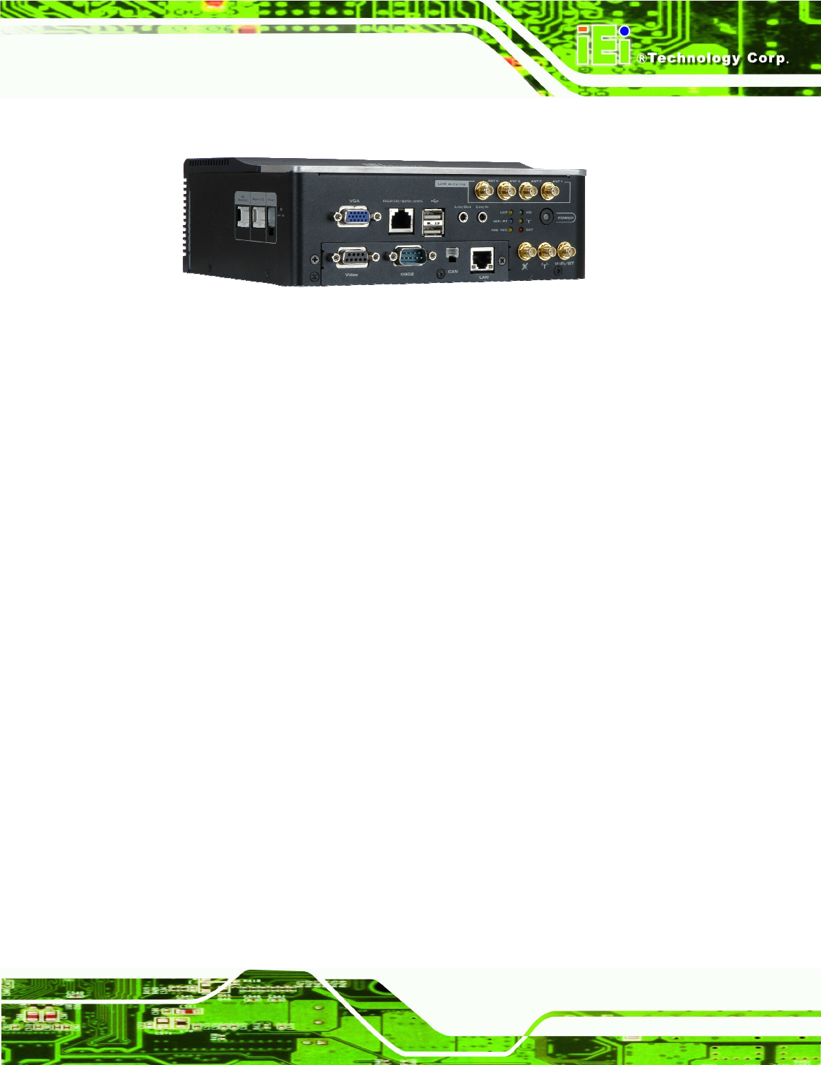
1.1 Overview
Figure 1-1: AVL-2000PLUS Auto Data Server
The AVL-2000PLUS is an embedded system for indoor only.
At the heart of the system is the Intel® Atom™ processor, offering low power in a powerful
package. The chipset is rounded off with the Intel® US15WP.
The system also offers HSUPA/GPRS/GSM connection, Global Position System (GPS)
and On-Board Diagnostic System (OBD) technology. Other peripherals include two USB
ports, an RS-232/422/485 port, one GbE port, video capture port and audio line-in and
line-out jacks. Wireless networking capabilities include Bluetooth 2.0 and 802.11 b/g.
1.2 Features
There are four models in the AVL-2000PLUS. Both models feature the following:
Fanless system with 1.1GHz Intel® Atom™ Z510 CPU
Pre-installed 1 GB 533 MHz DDR2 memory
Supports Windows XP, Windows 7 Embedded
Pre-installed 4 GB CF card for OS
SD card slot for data storage
VGA output port and NTSC/PAL video capture (120FPS@DI)
Network connectivity via HSDPA/GPRS/GSM, Wi-Fi and Bluetooth
RS-232/422/485 serial port (RJ-45 interface)
10/100/1000 Mbps Ethernet
Digital input/output supported
DIN rail mount support
Two USB ports
Audio line-in and line-out
AVL-2000PLUS Auto Data Server
Page 10
GPS system
Optional UHF RFID reader module
Supports OBD-II/FMS/J1939
RoHS compliance
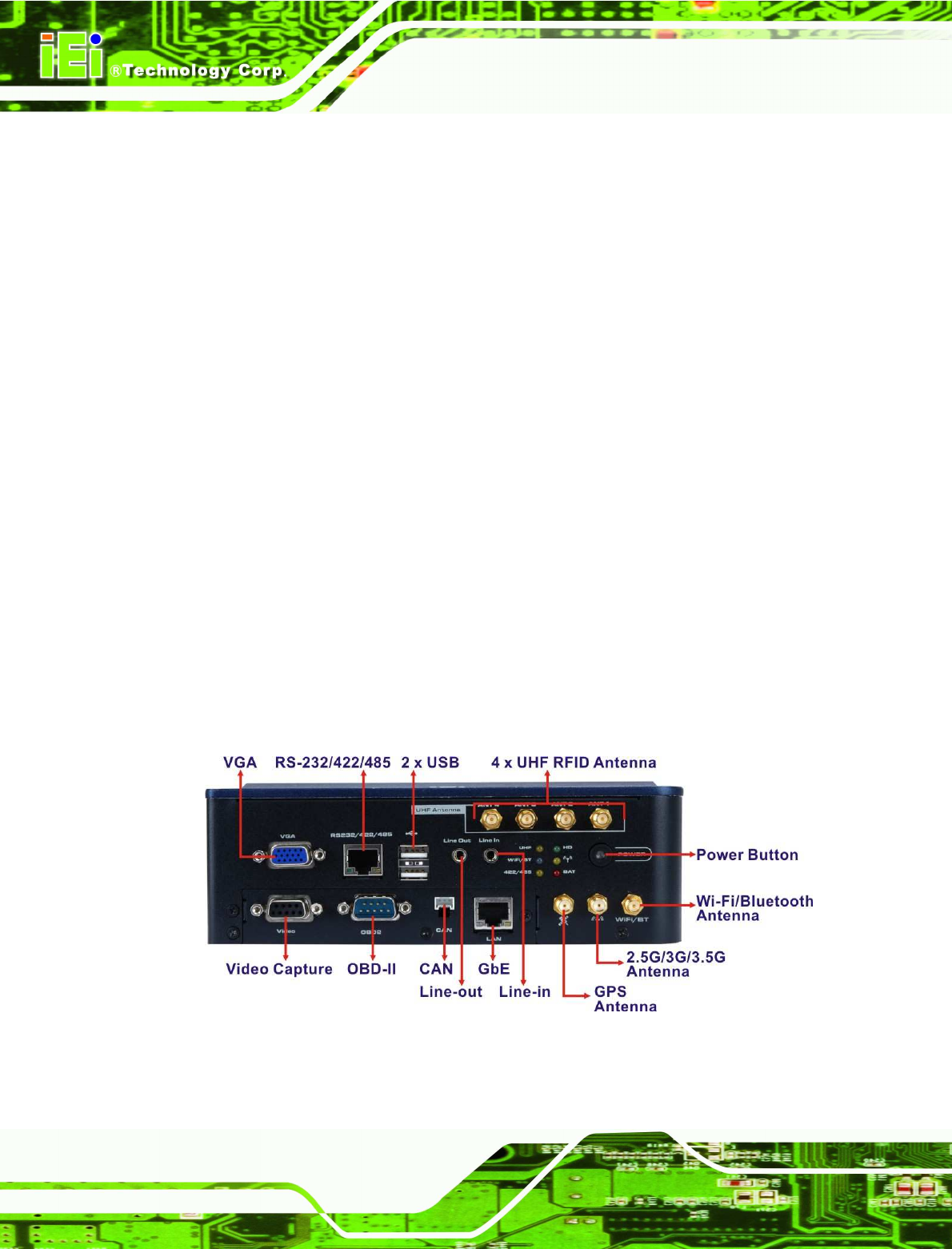
1.3 Front Panel
The following are found on the front panel.
1 x VGA connector
1 x Video capture connector
1 x RS-232/422/485 connector (RJ-45)
2 x USB ports
1 x Gigabit Ethernet RJ-45 port
1 x DB-9 connector (connects to OBD-II with included cable)
1 x CAN connector
1 x Audio line-in jack
1 x Audio line-out jack
1 x Power button
1 x GPS antenna connector
1 x 2.5G/3G/3.5G antenna connector
1 x Wi-Fi/Bluetooth antenna connector
4 x UHF RFID antenna connectors
Figure 1-2: Front Panel
AVL-2000PLUS Auto Data Server
Page 11
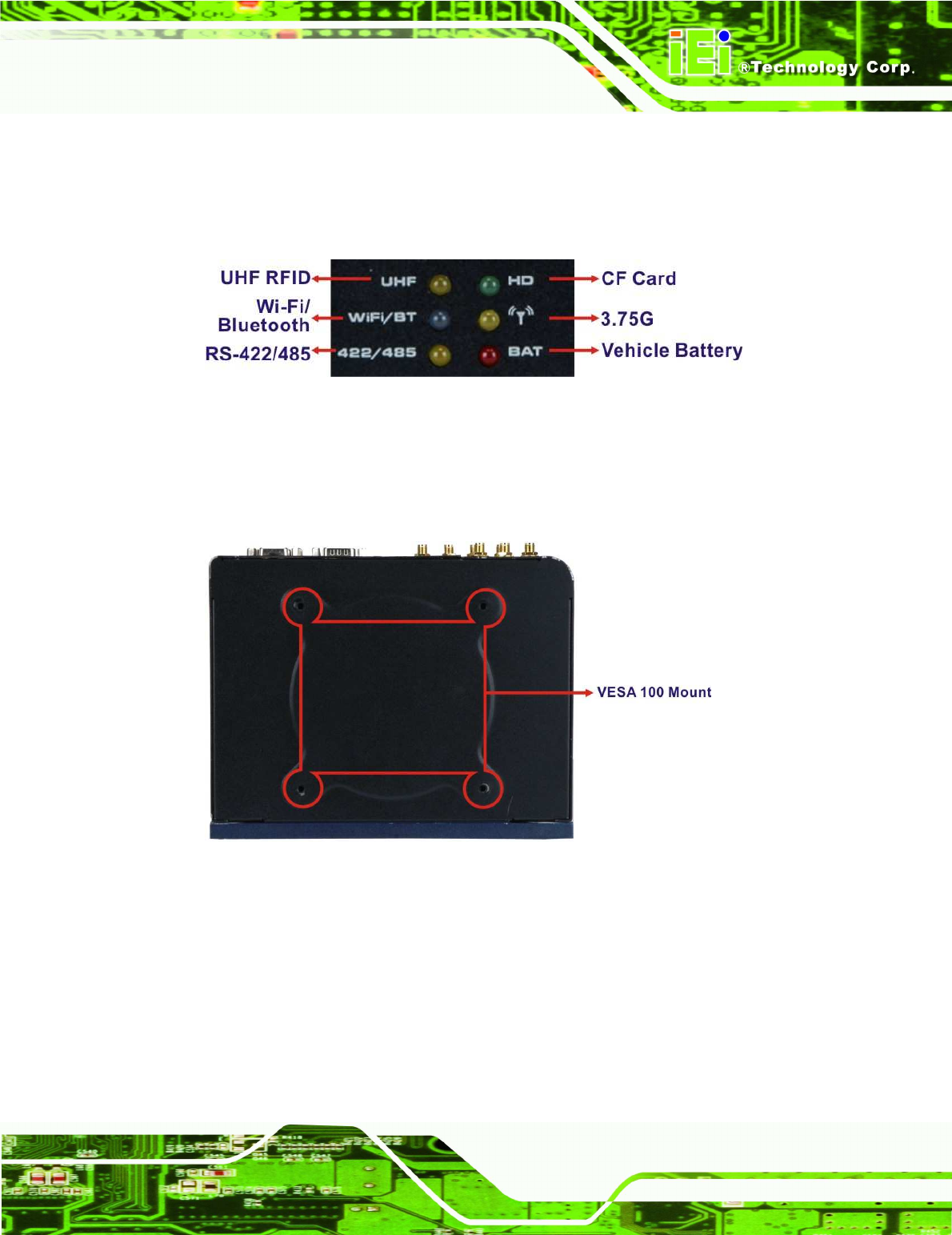
1.3.1 LED Indicators
The LED indicators on the front panel show the status of UHF RFID, Wi-Fi/Bluetooth,
RS-422/485, GPRS/HSUPA connection as well as CF card and battery activity.
Figure 1-3: LED Indicators
1.4 Rear Panel
The rear panel has VESA mounting screw holes for DIN rail mounting.
Figure 1-4: Rear View
AVL-2000PLUS Auto Data Server
Page 12
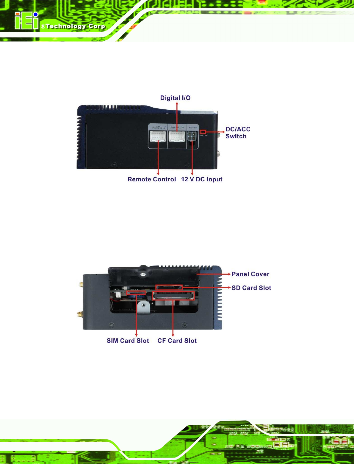
1.5 Right Panel
The right panel has one remote control connector, one digital I/O connector and one 12 V
DC power connector. The ACC/DC power switch is also located on the right panel.
Figure 1-5: Right Panel
1.6 Left Panel
The left panel provide access to the SD card slot, SIM card slot and CF card slot. These
slots are protected by a cover. After inset the SD card slot, SIM card slot or CF card shell
be closed the cover with screw before operation.
Figure 1-6: Left Panel
AVL-2000PLUS Auto Data Server
Page 13
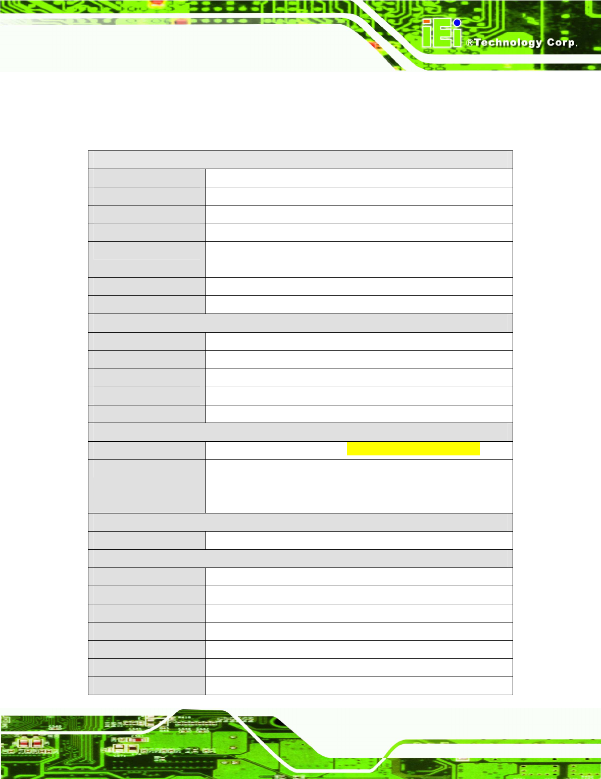
1.7 System Specifications
The technical specifications for the AVL-2000PLUS systems are listed in Table 1-1.
System
CPU 1.1 GHz Intel® Atom™ Z510
Chipset Intel® US15WP
Memory One 1.0 GB 533 MHz DDR2 pre-installed
OS Windows 7 Embedded
Storage 1 x 4 GB CompactFlash® card (500x) preinstalled
1 x SD card slot
Audio Realtek ALC888
Digital I/O 4 inputs / 4 outputs
Communication
LAN 1 x 10/100/1000 Mbps RJ-45
Wireless LAN 802.11b/g
Bluetooth Bluetooth 2.0 + EDR Class 1
Data Rate WCDMA/HSUPA
GPS Support GPS
Data Collection
RFID Optional ISO 18000-6C UHF RFID operation frequency 915MHz 0nly
Video Capture Video input: 4-channel composite video (NTSC/PAL/SECAM)
Frame rate: four channels with 120fps@D1 per channel (NTSC), four
channels with 100fps@D1 per channel (PAL/SECAM)
Power
Power Input 9~30 V DC input
Physical Character
Mounting DIN rail mount (VESA 100 mm x 100 mm)
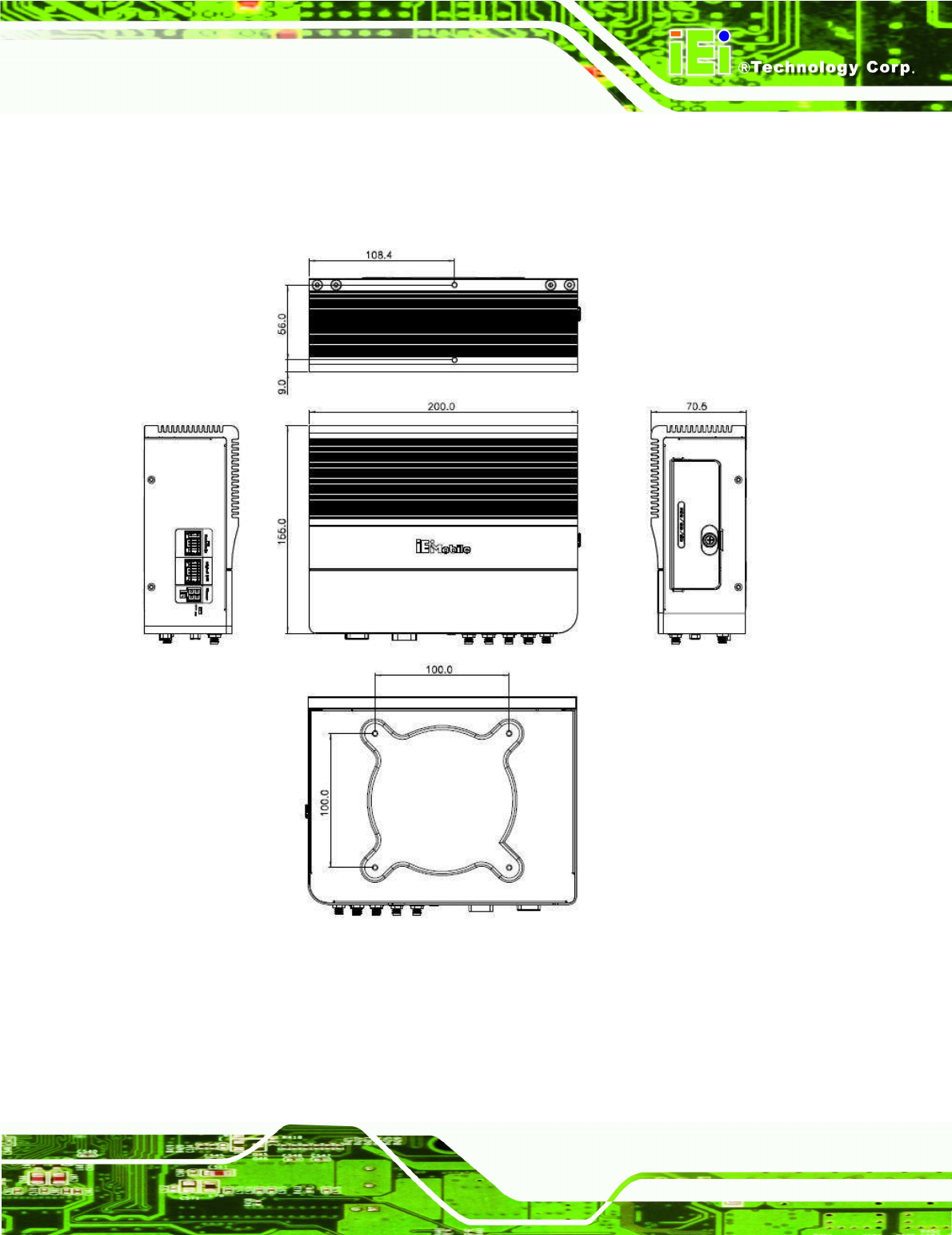
Dimensions (W x D x H)
200 mm x 155 mm x 70 mm
Operation Temperature
-20ºC ~ 40ºC
Storage Temperature -30ºC ~ 80ºC
Humidity 5% ~ 95% non-condense
Net weight 1.978 kg
Safety CE, FCC, CCC, E-MARK
AVL-2000PLUS Auto Data Server
Page 14
Connectors and Buttons
Antenna Connectors 1 x GPS antenna connector
1 x 2.5G/3G/3.5G antenna connector
1 x Wi-Fi/Bluetooth antenna connector
4 x UHF RFID antenna connectors
I/O Ports and Switches
1 x Power connector
1 x VGA connector
1 x Video capture connector
1 x RS-232/422/485 connector (RJ-45)
2 x USB ports
1 x Gigabit Ethernet RJ-45 port
1 x DB-9 connector (connects to OBD-II with included cable)
1 x CAN connector
1 x Audio line-in jack
1 x Audio line-out jack
1 x Digital I/O connector
Button and Switch 1 x Power button
1 x ACC/DC switch
Table 1-1: Technical Specifications
AVL-2000PLUS Auto Data Server
Page 15
1.8 Dimensions
The dimensions are shown below.
Figure 1-7: Dimensions (unit: mm)
AVL-2000PLUS Auto Data Server
Page 16
Chapter
2
2 Unpacking
AVL-2000PLUS Auto Data Server
Page 17
To unpack the AVL-2000PLUS, follow the steps below:
Step 1: Use box cutters, a knife or a sharp pair of scissors that seals the top side of the
external (second) box.
Step 2: Open the external (second) box.
Step 3: Use box cutters, a knife or a sharp pair of scissors that seals the top side of the
internal (first) box.
Step 4: Lift the monitor out of the boxes.
Step 5: Remove both polystyrene ends, one from each side.
Step 6: Pull the plastic cover off the AVL-2000PLUS.
Step 7: Make sure all the components listed in the packing list are present. Step 0:
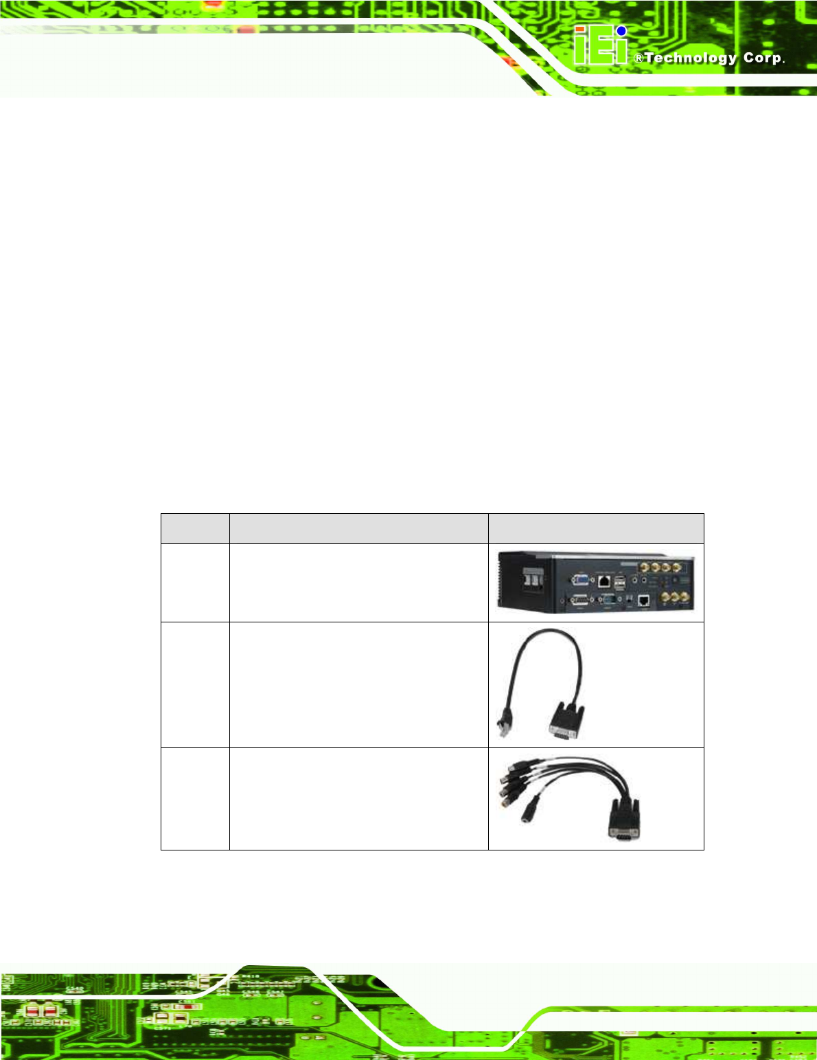
The AVL-2000PLUS is shipped with the following components:
Quantity
Item Image
1 AVL-2000PLUS
1 RS-232 cable
(P/N: 32005-000200-200-RS)
1 Capture cable
(P/N: 32007-001400-100-RS)
AVL-2000PLUS Auto Data Server
Page 18
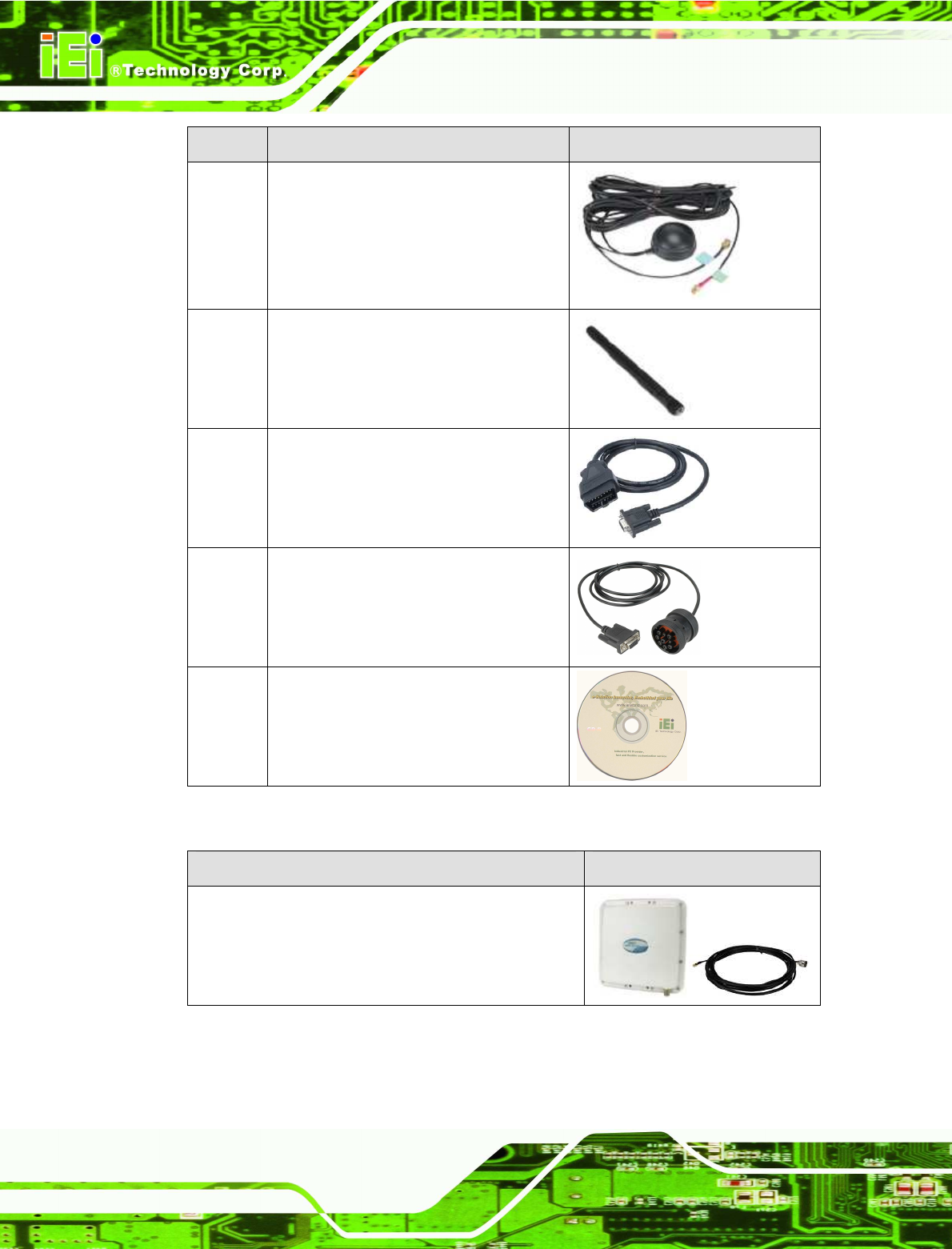
Quantity
Item Image
1 GPS/GSM antenna
(P/N: 32506-000100-100-RS)
1 Wi-Fi/Bluetooth antenna
(P/N: 32505-000400-100-RS)
1 OBD-II cable
(P/N: 32025-000300-100-RS)
1 J1939/FMS cable
(P/N: 32025-000400-100-RS)
1 User manual CD and driver CD
Table 2-1: Packing List
Item Image
UHF RFID antenna with cable
Table 2-2: Optional Items
AVL-2000PLUS Auto Data Server
Page 19
If any of these items are missing or damaged, contact the distributor or sales
representative immediately.
AVL-2000PLUS Auto Data Server
Page 20
Chapter
3
3 Installation
AVL-2000PLUS Auto Data Server
Page 21
3.1 Anti-static Precautions
WARNING:
Failure to take ESD precautions during the maintenance of the
AVL-2000PLUS may result in permanent damage to the
AVL-2000PLUS and severe injury to the user.
Electrostatic discharge (ESD) can cause serious damage to electronic components,
including the AVL-2000PLUS. Dry climates are especially susceptible to ESD. It is
therefore critical that whenever the AVL-2000PLUS is accessed internally, or any other
electrical component is handled, the following anti-static precautions are strictly adhered
to.
Wear an anti-static wristband: - Wearing a simple anti-static wristband can
help to prevent ESD from damaging the board.
Self-grounding: - Before handling the board touch any grounded conducting
material. During the time the board is handled, frequently touch any
conducting materials that are connected to the ground.
Use an anti-static pad: - When configuring the AVL-2000PLUS, place it on
an antic-static pad. This reduces the possibility of ESD damaging the
AVL-2000PLUS.
Only handle the edges of the PCB: - When handling the PCB, hold the PCB
by the edges.
3.2 Installation Precautions
When installing the AVL-2000PLUS, please follow the precautions listed below:
Power turned off: When installing the AVL-2000PLUS, make sure the power
is off. Failing to turn off the power may cause severe injury to the body and/or
damage to the system.
Certified Engineers: Only certified engineers should install and modify
onboard functionalities.
AVL-2000PLUS Auto Data Server
Page 22
Anti-static Discharge: If a user open the bottom panel of the AVL-2000PLUS,
to configure the jumpers or plug in added peripheral devices, ground
themselves first and wear and anti-static wristband.
3.3 Installation and Configuration Steps
The following installation steps must be followed.
Step 1: Unpack the system
Step 2: Install a SIM card or SD card (optional)
Step 3: Connect peripheral devices
Step 4: Mount the system
Step 5: Power up the system Step 0:
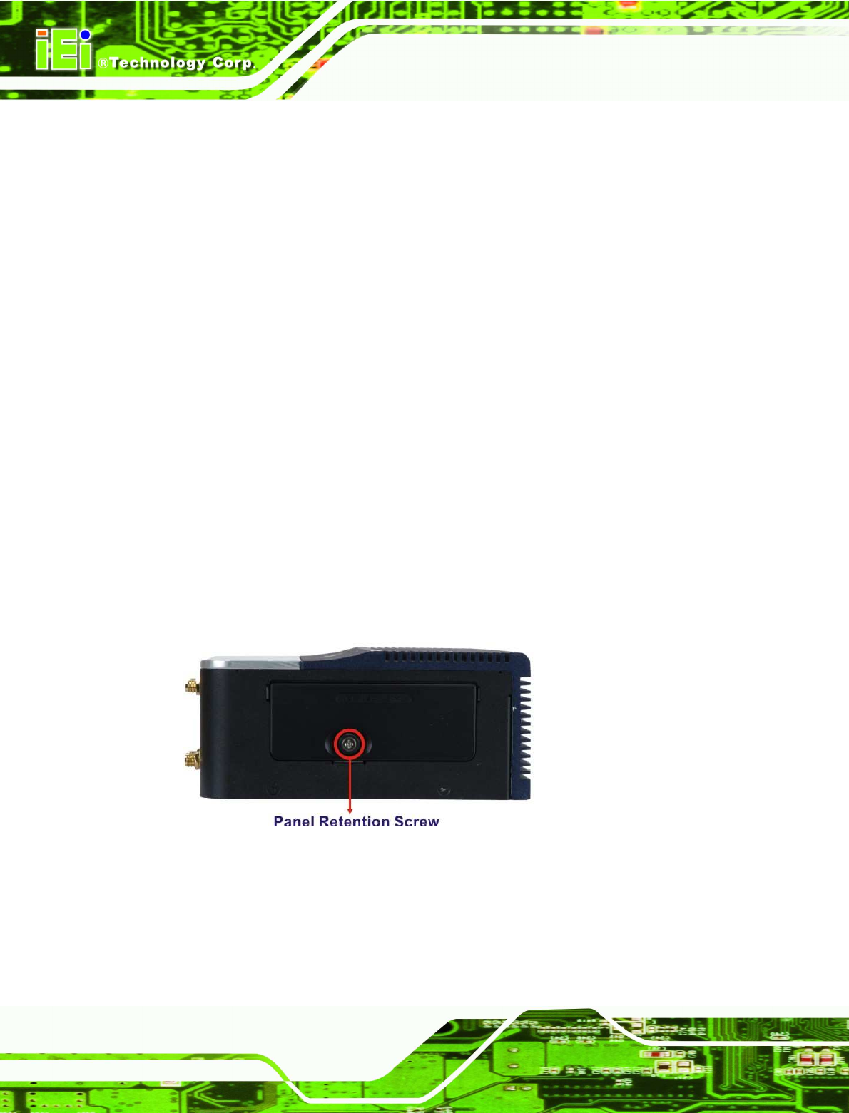
3.4 SIM Card and SD Card Installation
To install a SIM card or a SD card, the cover plate must be removed. To remove the cover
plate and install the SIM card or the SD card, follow the instructions below.
Step 1: Remove the retention screw and lift the cover.
Figure 3-1: Panel Retention Screw
AVL-2000PLUS Auto Data Server
Page 23
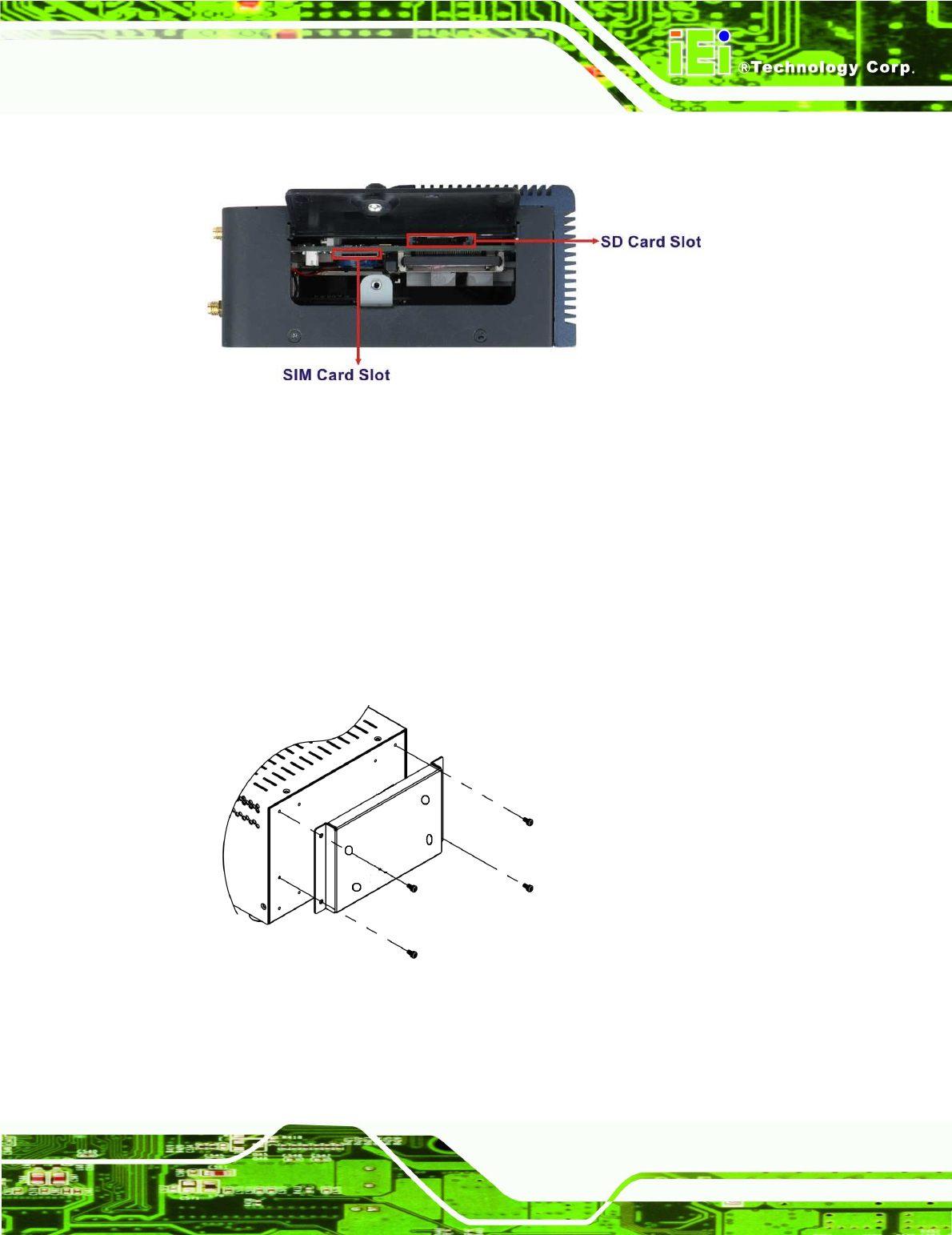
Step 2: Locate the SIM card slot or SD card slot. See Figure 3-2.
Figure 3-2: Slot Locations
Step 3: Insert the card into the correspondent slot.Step 0:
3.5 Mounting the System
To mount the system onto a VESA bracket, please follow the steps below.
Step 1: Attach theVESA mounting bracket to the bottom panel of the AVL-2000PLUS.
Secure the bracket to the AVL-2000PLUS with the supplied retention screws
(
762H762H
Figure 3-3).
Figure 3-3: VESA Mounting Bracket
AVL-2000PLUS Auto Data Server
Page 24
3.6 I/O Interface Connectors
This section provides an overview of the I/O interface connectors of the AVL-2000PLUS.
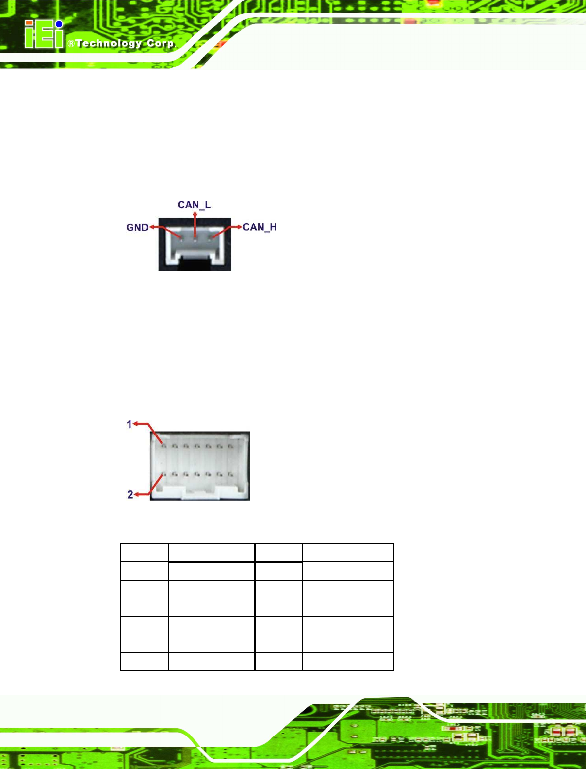
3.6.1 CAN Bus Connection
There is one 3-pin CAN Bus connector. The connector pinouts are shown in
Figure 3-4: CAN Bus Connector Pinouts
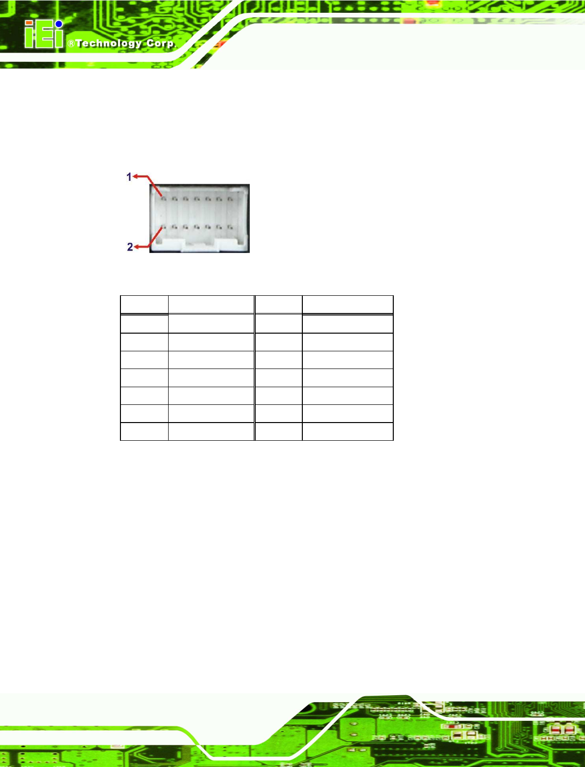
3.6.2 Digital I/O Connection
The AVL-2000PLUS right side panel has one 14-pin wafer connector for digital I/O
connection. The pinouts for digital I/O connector are listed in the table below.
Figure 3-5: Digital I/O Connector Pinouts Location
PIN NO.
DESCRIPTION PIN NO.
DESCRIPTION
1 ISO_GND 2 ISO_5V
3 GPI0_ISO 4 GPI1_ISO
5 GPI2_ISO 6 GPI3_ISO
7 GPO0_ISO 8 GPO1_ISO
9 GPO2_ISO# 10 GPO3_ISO
11 GND 12 VCC5
AVL-2000PLUS Auto Data Server
Page 25
13 SPEED_IN+ 14 SPEED_IN-
Table 3-1: Digital I/O Connector Pinouts
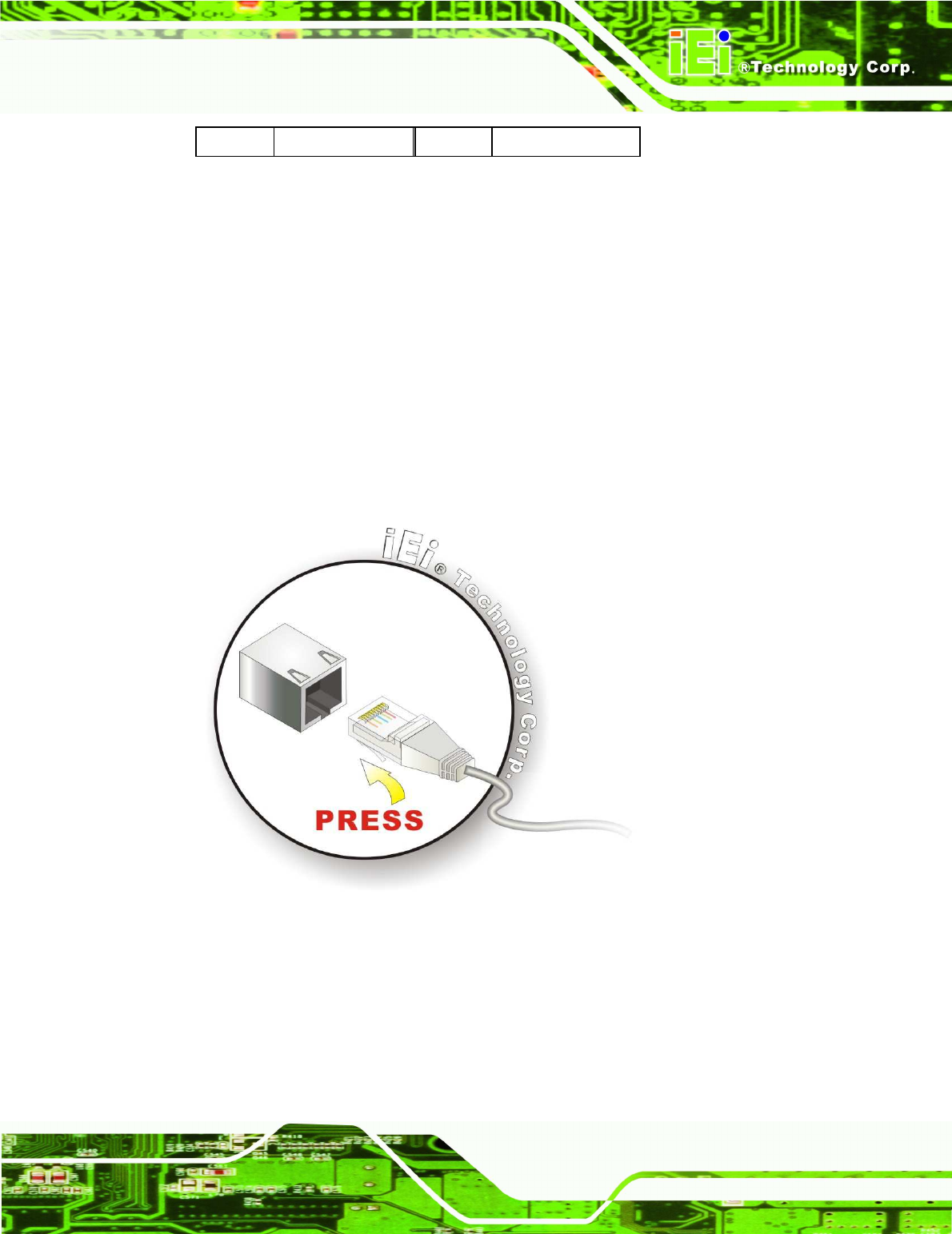
3.6.3 LAN Connection
There is one external RJ-45 LAN connector. The RJ-45 connector enables connection to
an external network. To connect a LAN cable with an RJ-45 connector, please follow the
instructions below.
Step 1: Locate the RJ-45 connectors on the bottom panel of the AVL-2000PLUS.
Step 2: Align the connectors. Align the RJ-45 connector on the LAN cable with one of
the RJ-45 connectors on the bottom panel of the AVL-2000PLUS.
Figure 3-6: LAN Connection
Step 3: Insert the LAN cable RJ-45 connector. Once aligned, gently insert the LAN
cable RJ-45 connector into the onboard RJ-45 connector. Step 0:
AVL-2000PLUS Auto Data Server
Page 26
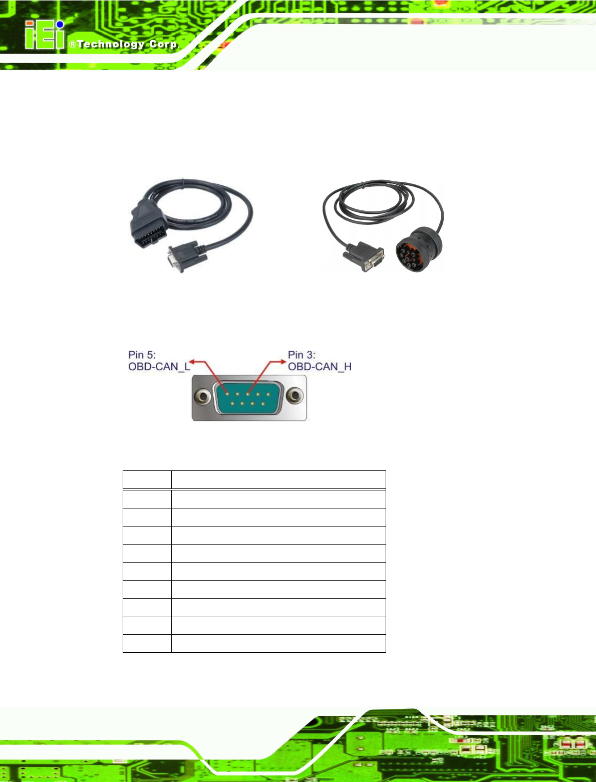
3.6.4 OBD-II Connector
The AVL-2000PLUS has one DB-9 male connector for OBD-II connection. Use the OBD-II
cable or J1939/FMS cable (Figure 3-7) in the package to connect the AVL-2000PLUS.
OBD-II Cable
J1939/FMS Cable
Figure 3-7: OBD-II Cable and J1939/FMS Cable
The pinouts for OBD-II connector are listed in the table below.
Figure 3-8: OBD-II Connector Pinouts Location
Pin Description
1 NC
2 NC
3 OBD-CAN_H
4 ISO-9141-2-K
5 OBD-CAN_L
6 J1850-
7 J1850+
8 ISO-9141-2-L
9 NC
Table 3-2: OBD-II Connector Pinouts
AVL-2000PLUS Auto Data Server
Page 27
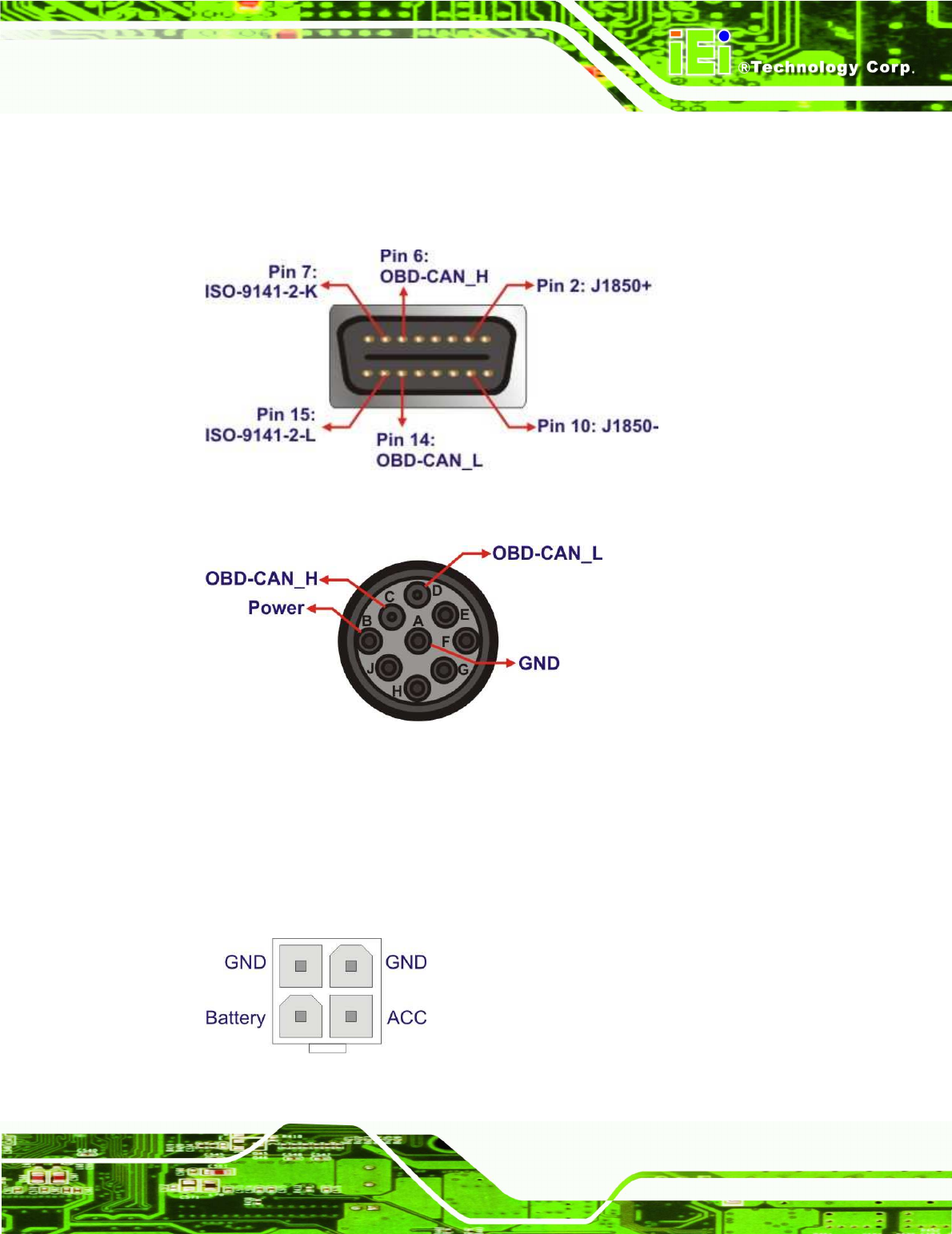
The pinout locations of OBD-II cable connector and J1939/FMS cable connector are
shown below.
Figure 3-9: OBD-II Connector Pinouts
Figure 3-10: J1939/FMS Connector Pinouts
3.6.5 Power Input Connection
The AVL-2000PLUS has one 12 V DC input connector on the right panel.
Figure 3-11: Power Input Connector
AVL-2000PLUS Auto Data Server
Page 28
3.6.6 Remote Control Connection
The AVL-2000PLUS right side panel has one 14-pin wafer connector for the optional
remote control connection. The pinouts for remote control connector are listed in the table
below.
Figure 3-12: Remote Control Connector Pinouts Location
PIN NO.
DESCRIPTION PIN NO.
DESCRIPTION
1 PWR_BTN 2 GND
3 FU1 4 GND
5 FU2 6 GND
7 FU3 8 GND
9 PW_BAT_LED# 10 GND
11 HDD_LED 12 3.5G_LED
13 BT_LED 14 WIFI_LED
Table 3-3: Remote Control Connector Pinouts
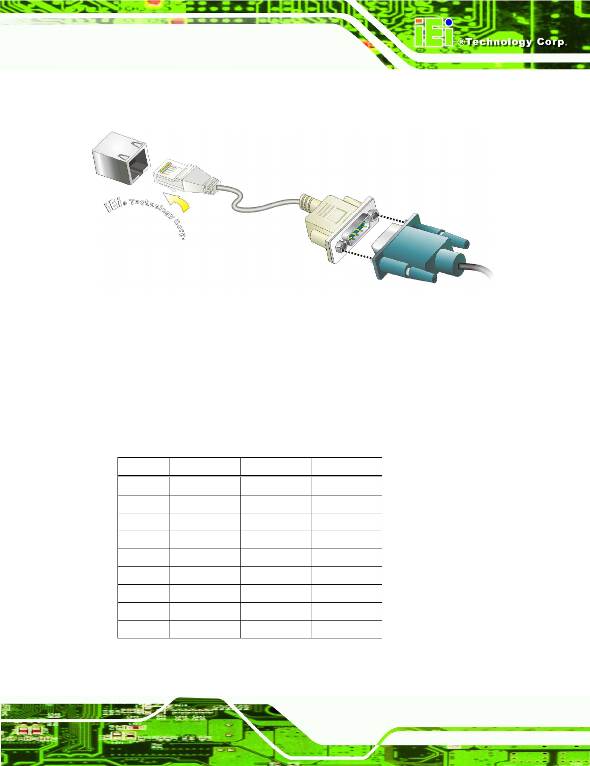
3.6.7 Serial Device Connection
The AVL-2000PLUS has one male RJ-45 connector on the bottom panel for serial devices
to be connected. Follow the steps below to connect a serial device to the AVL-2000PLUS.
Step 1: Locate the RJ-45 connector. The location of the RJ-45 serial port connector is
shown in Chapter 1. The RJ-45 connectors for the serial ports can be identified
easily as the RJ-45 for the network has two LEDs on the port, while the
connectors for the serial cables don’t.
Step 2: Insert the RJ-45 to DB-9 cable.
AVL-2000PLUS Auto Data Server
Page 29
Step 3: Insert the serial connector. Insert the DB-9 connector of a serial device into
the DB-9 connector on the cable. See Figure 3-13.
Figure 3-13: Serial Device Connector
Step 4: Secure the connector. Secure the serial device connector to the external
interface by tightening the two retention screws on either side of the connector.
3.6.7.1 COM1 Pinouts
The COM1 connector can be set as RS-232 (default), RS-422 or RS-485 in BIOS. The
pinouts for COM1 are listed in the table below.
Pin RS-232 RS-422 RS-485
1 NRI1
2 NDTR1
3 NCTS1
4 NTX1 TX- DATA-
5 NRTS1 TX+ DATA+
6 NRX1 RX+
7 NDSR1
8 NDCD1 RX-
9 GND GND GND
Table 3-4: COM1 Connector Pinouts
AVL-2000PLUS Auto Data Server
Page 30
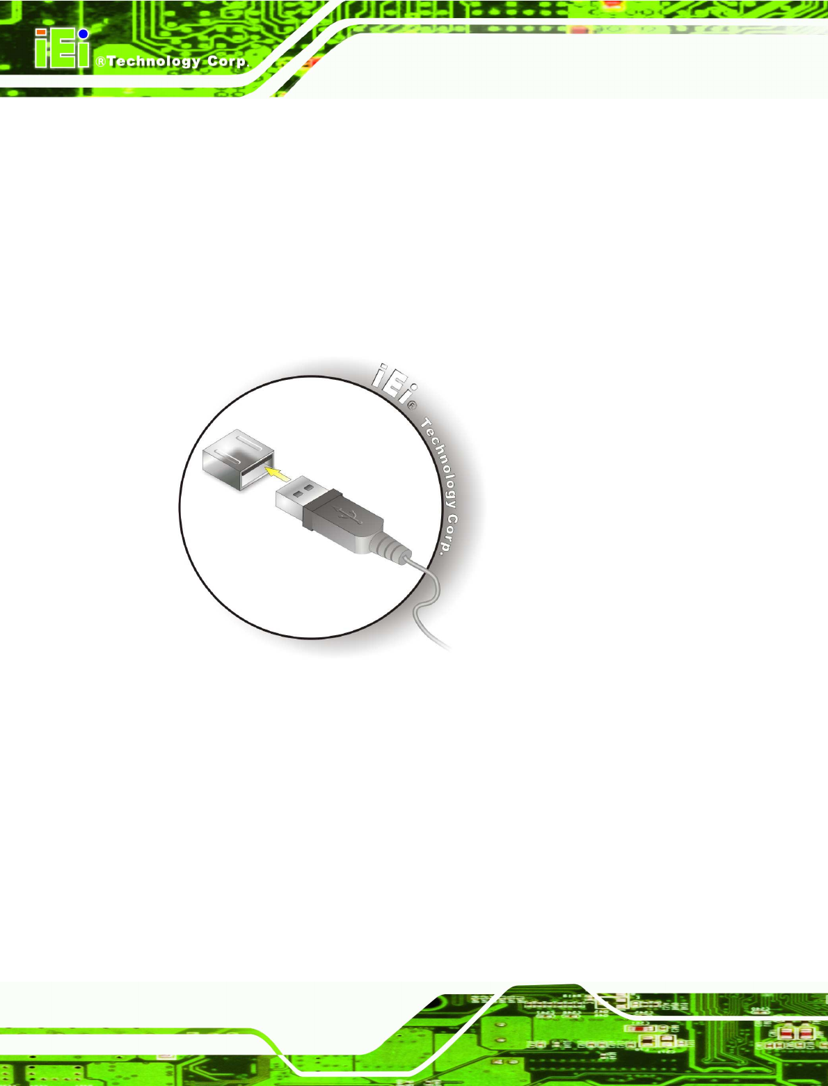
3.6.8 USB Device Connection
There are two external USB connectors. To connect a USB device, please follow the
instructions below.
Step 1: Located the USB connectors. The locations of the USB connectors are shown
in Chapter 2.
Step 2: Align the connectors. Align the USB device connector with one of the
connectors on the bottom panel.
Figure 3-14: USB Device Connection
Step 3: Insert the device connector. Once aligned, gently insert the USB device
connector into the onboard connector. Step 0:
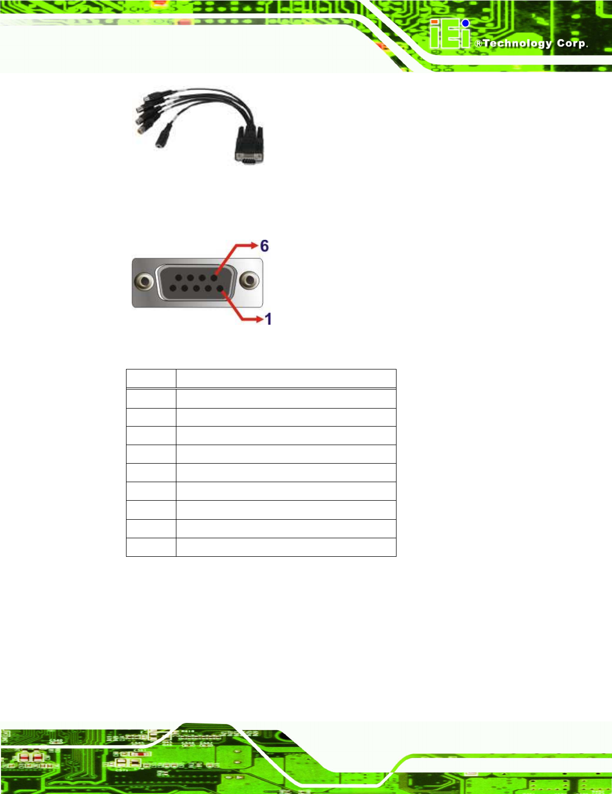
3.6.9 Video Capture Connection
The AVL-2000PLUS has one DB-9 female connector for video capture connection. Use
the video cable (Figure 3-7) in the package to connect the AVL-2000PLUS with the
device.
AVL-2000PLUS Auto Data Server
Page 31
Figure 3-15: Video Capture Cable
The pinouts for video connector are listed in the table below.
Figure 3-16: Video Connector Pinouts Location
Pin Description
1 CN1_A
2 CN1_B
3 CN1_C
4 CN1_D
5 SIN1_A
6 GND
7 GND
8 GND
9 GND
Table 3-5: Video Connector Pinouts
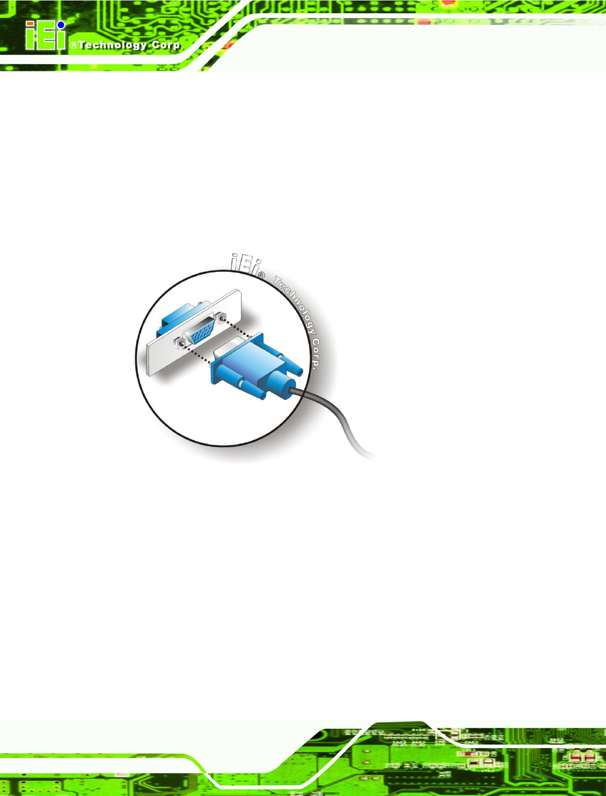
3.6.10 VGA Monitor Connection
The AVL-2000PLUS has a single female DB-15 connector on the external peripheral
interface panel. The DB-15 connector is connected to a CRT or VGA monitor. To connect
a monitor to the AVL-2000PLUS, please follow the instructions below.
AVL-2000PLUS Auto Data Server
Page 32
Step 1: Locate the female DB-15 connector. The location of the female DB-15
connector is shown in Chapter 3.
Step 2: Align the VGA connector. Align the male DB-15 connector on the VGA screen
cable with the female DB-15 connector on the external peripheral interface.
Step 3: Insert the VGA connector. Once the connectors are properly aligned with the
insert the male connector from the VGA screen into the female connector on the
AVL-2000PLUS. See Figure 3-17.
Figure 3-17: VGA Connector
Step 4: Secure the connector. Secure the DB-15 VGA connector from the VGA
monitor to the external interface by tightening the two retention screws on either
side of the connector. Step 0:
3.7 System Maintenance
If the components of the AVL-2000PLUS fail, they must be replaced. Please contact the
system reseller or vendor to purchase the replacement parts.
AVL-2000PLUS Auto Data Server
Page 33
NOTE:
A user cannot replace a motherboard. If the motherboard fails it must
be shipped back to IEI to be replaced. Please contact the system
vendor, reseller or an IEI sales person directly.
Federal Communication Commission Interference Statement
This equipment has been tested and found to comply with the limits for a Class B
digital device, pursuant to Part 15 of the FCC Rules. These limits are designed
to provide reasonable protection against harmful interference in a residential
installation. This equipment generates, uses and can radiate radio frequency
energy and, if not installed and used in accordance with the instructions, may
cause harmful interference to radio communications. However, there is no
guarantee that interference will not occur in a particular installation. If this
equipment does cause harmful interference to radio or television reception, which
can be determined by turning the equipment off and on, the user is encouraged to
try to correct the interference by one of the following measures:
- Reorient or relocate the receiving antenna.
- Increase the separation between the equipment and receiver.
- Connect the equipment into an outlet on a circuit different from that
to which the receiver is connected.
- Consult the dealer or an experienced radio/TV technician for help.
FCC Caution: Any changes or modifications not expressly approved by the party
responsible for compliance could void the user's authority to operate this
equipment.
This device complies with Part 15 of the FCC Rules. Operation is subject to the
following two conditions: (1) This device may not cause harmful interference, and
(2) this device must accept any interference received, including interference that
may cause undesired operation.
AVL-2000PLUS Auto Data Server
Page 34
Radiation Exposure Statement:
This equipment complies with FCC radiation exposure limits set forth for an
uncontrolled environment. This equipment should be installed and operated
with minimum distance 20cm between the radiator & your body.