IKEA of Sweden ICC-1 RF module User Manual ICC1 Module Description IKEA 0 7
IKEA of Sweden AB RF module ICC1 Module Description IKEA 0 7
User Manual
Document name: ICC-1 connectivity module Revision: 0.7
FCC ID: FHO-ICC-1 Revision date: 2016-07-05
IC ID: 10912A-ICC1
© Inter IKEA Systems B.V. 2016 Page 1 of 17
ICC-1 connectivity module
Document ID: SCDOC-129-142
Author’s name: Olof Blomé
Approver’s name: Tomas Mellblom
Revision Author’s name Comment Revision date
0.1 Olof Blomé Document created 2016-03-08
0.2 Olof Blomé Formatting 2016-03-09
0.3 Olof Blomé Added:
• Antenna gain -2.5dBi
• Limitations on usage
• Label guidance
User manual regulatory info
2016-04-24
0.4 Sigma Connectivity Added additional required host label text 2016-05-04
0.5 Sigma Connectivity Layout updates
Added limitation update
2016-05-16
0.6 Sigma Connectivity Added info about the limited modular approval
(LMA) for ICC-1 NA 2016-06-30
0.7 Sigma Connectivity Added additional info in limitations. 2016-07-05

Document name: ICC-1 connectivity module Revision: 0.7
FCC ID: FHO-ICC-1 Revision date: 2016-07-05
IC ID: 10912A-ICC1
© Inter IKEA Systems B.V. 2016 Page 2 of 17
Contents
1
ICC-1 module description ................................................................................. 4
1.1
Description of ICC-1 .................................................................................. 4
1.2
Pin description.......................................................................................... 5
1.3
Radio front-end and crystal ........................................................................ 6
1.4
Type approval markings............................................................................. 6
1.5
Module physical size and footprint............................................................... 7
1.6
Mounting options ...................................................................................... 7
2
Design rules for antenna integration .................................................................. 8
2.1
Distance to metal objects........................................................................... 9
2.2
Distance to plastic objects.......................................................................... 9
2.3
Grounding of metal heat sink.................................................................... 10
2.4
Module mounting options ......................................................................... 11
3
Power supply for ICC-1................................................................................... 12
3.1
Regulated power supply........................................................................... 12
3.2
Coin cell battery operation ....................................................................... 12
4
Electrical specifications................................................................................... 13
4.1
Absolute maximum ratings....................................................................... 13
4.2
Recommended operating conditions .......................................................... 13
4.3
Environmental ........................................................................................ 13
4.4
Transceiver characteristics ....................................................................... 14
4.5
Wake up timing ...................................................................................... 14
4.6
General purpose input/output................................................................... 14
5
Regulatory instructions................................................................................... 15
5.1
Limitations ............................................................................................. 15
5.2
User manual........................................................................................... 15
5.3
Label ..................................................................................................... 15
6
Certification .................................................................................................. 16

Document name: ICC-1 connectivity module Revision: 0.7
FCC ID: FHO-ICC-1 Revision date: 2016-07-05
IC ID: 10912A-ICC1
© Inter IKEA Systems B.V. 2016 Page 3 of 17
6.1
FCC statement........................................................................................ 16
6.2
Industry Canada statement ...................................................................... 17
Figures
Figure 1 - Module with shield can ............................................................................ 4
Figure 2 - Overview pin out numbering for ICC-1 ......................................................5
Figure 3 - Silkscreen printing .................................................................................. 6
Figure 5 - Physical dimensions of the ICC-1 module................................................... 7
Figure 6 - Antenna area front and back of module ..................................................... 8
Figure 7 - Metal free area to secure antenna performance .......................................... 9
Figure 8 - Suggested grounding point .................................................................... 10
Figure 9 - Grounding point for heatsink.................................................................. 10
Figure 10 - Mounted 90 degree angle .................................................................... 11
Figure 11 - Flat board-to-board connection............................................................. 11
Document name: ICC-1 connectivity module Revision: 0.7
FCC ID: FHO-ICC-1 Revision date: 2016-07-05
IC ID: 10912A-ICC1
© Inter IKEA Systems B.V. 2016 Page 4 of 17
1 ICC-1 module description
ICC-1 is a ZigBee module with integrated antenna with highly flexible input and output
options. The ICC-1 module will be integrated within the IKEA TRÅDFRI wireless product
range and is not a standalone product.
• IEEE Std- 802.15.4 compliant RF transceiver
• Supports ZigBee / Bluetooth Low Energy (BLE) / Thread on 2.4 GHz ISM band
• Output power maximum 10 dBm e.i.r.p and sensitivity up to -97 e.i.r.p with built-
in PCB antenna
• Operational within -40°C to 125°C
• Module size is approximately 18.0 mm x 24.5 mm
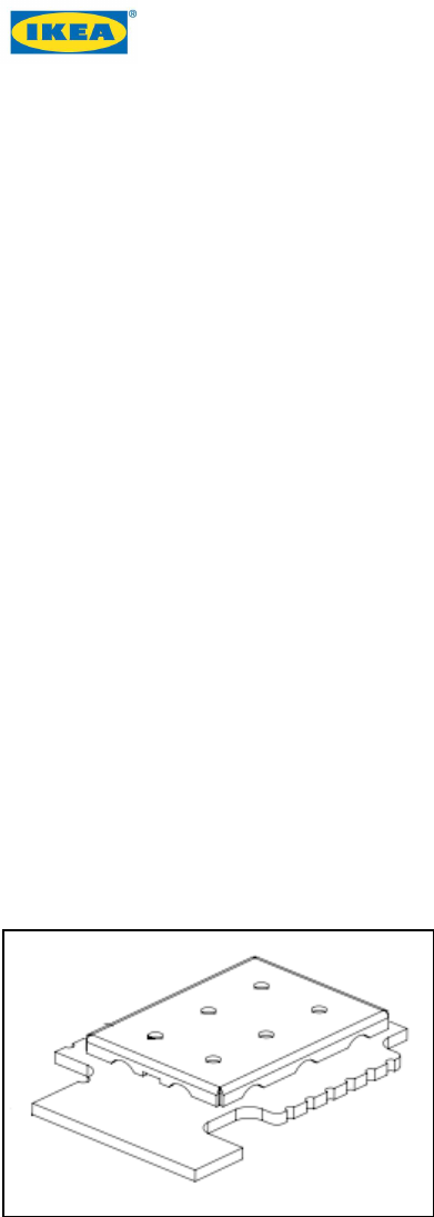
1.1 Description of ICC-1
• 2.4 GHz 802.15.4 compliant module with multiple mounting options and
configurations.
• 17 connections, 6 pins on the left and 10 pins on the right.
• 12 connections can be used as General-purpose input/output (GPIO) connections.
• Working temperature range -40° C to +125° C.
• Built-in thermistor to compensate crystal drift to control temperature variations.
Figure 1 - Module with shield can
Document name: ICC-1 connectivity module Revision: 0.7
FCC ID: FHO-ICC-1 Revision date: 2016-07-05
IC ID: 10912A-ICC1
© Inter IKEA Systems B.V. 2016 Page 5 of 17
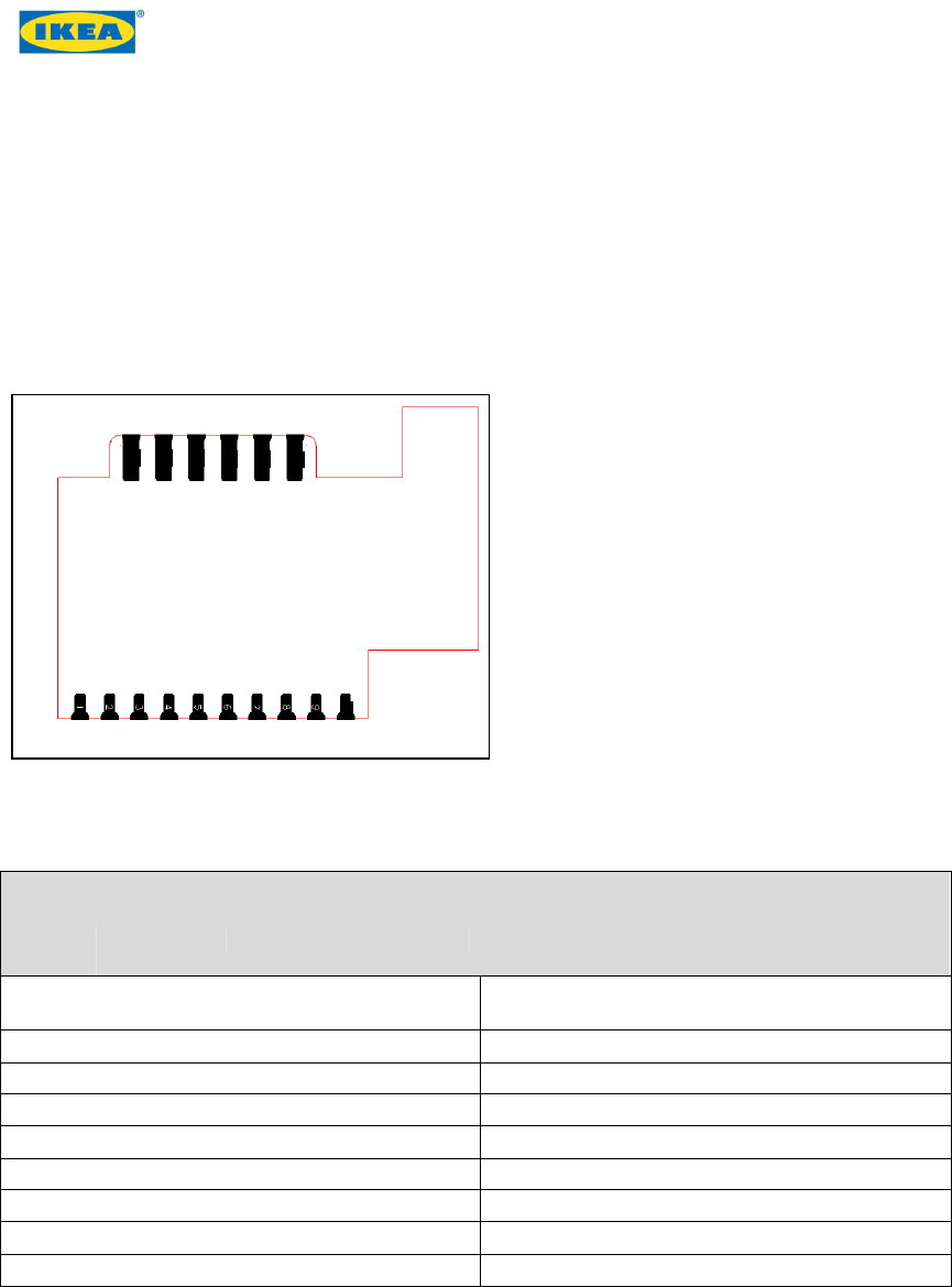
1.2 Pin description
The pin out is flexible and all pins can be configured as analogue port or data channel,
such as I2C. Each GPIO has its own mux configuration and set of PU and PD. The
software is defied for each product.
The pin number is counted from the lower left corner, see Figure 2.
Figure 2 - Overview pin out numbering for ICC-1
Pin description
Pin
number
Logic
number
Notes Pin
number
Logic
number
Notes
1 GND Connected to main
ground 10 RESETn Hardware reset
2 PB15 GPIO 11 VDD Power supply
3 PB14 GPIO 12 GND Ground
4 PC10 GPIO 13 PB13 GPIO
5 PC11 GPIO 14 PB12 GPIO
6 PF0 DBG_SWCLKTCK 15 PA1 GPIO
7 PF1 DBG_SWDIOTMS 16 PA0 GPIO
8 PF2 DBG_SWO 17 PC11 FTM
9 PF3 DBG_TDI
11
12
13
14
15
16
1
2
3
4
5
6
7
8
9
10

Document name: ICC-1 connectivity module Revision: 0.7
FCC ID: FHO-ICC-1 Revision date: 2016-07-05
IC ID: 10912A-ICC1
© Inter IKEA Systems B.V. 2016 Page 6 of 17
1.3 Radio front-end and crystal
The ICC-1 radio chipset has a built-in balun. The radio output is connected to an antenna
using a wave guide type of trace to minimize losses because of the two-layer structure of
the PCB. The front-end has a discrete RF-filter to comply with harmonic emission
regulations. The radio uses an XO with integrated frequency control via built-in
thermistor to cover the wide temperature range.
If a stable slow clock source is needed, oscillators can be calibrated in runtime instead of
using a dedicated 32 kHz clock.
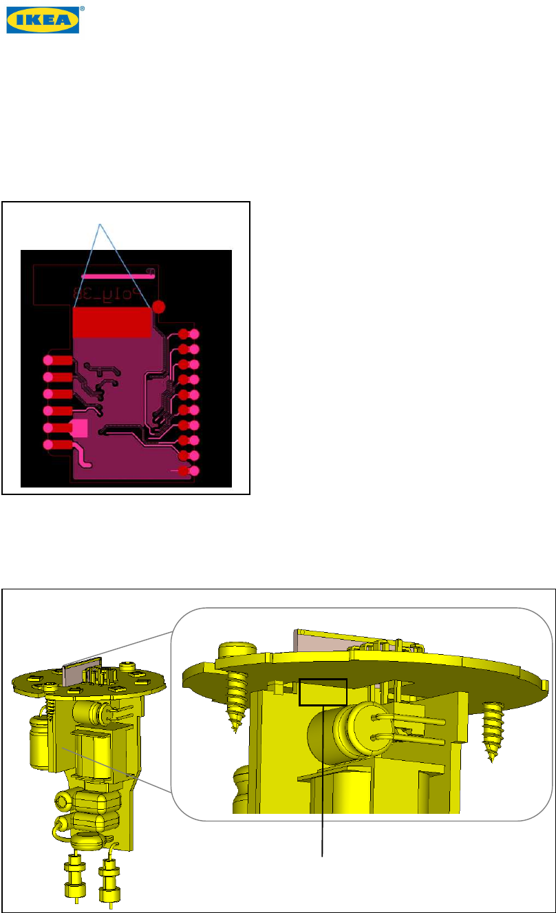
1.4 Type approval markings
The ICC-1 module has a FCC ID and Industry Canada (IC) number silkscreen printing for
reference located at the bottom. The host shall be labelled with Contains Transmitter
Module FCC ID: FHO-ICC-1 and IC: 10912A-ICC1.
• ICC-1
• FCC ID: FHO-ICC-1
• IC: 10912A-ICC1
Figure 3 - Silkscreen printing
Document name: ICC-1 connectivity module Revision: 0.7
FCC ID: FHO-ICC-1 Revision date: 2016-07-05
IC ID: 10912A-ICC1
© Inter IKEA Systems B.V. 2016 Page 7 of 17
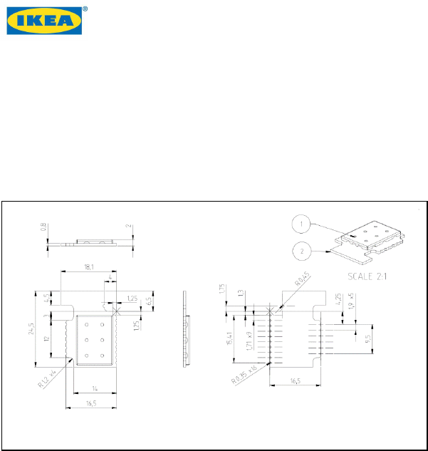
1.5 Module physical size and footprint
• Total width: 18 mm x 24.5 mm
• Height, including PCB and shield can: 2.1 mm
Figure 4 - Physical dimensions of the ICC-1 module
1.6 Mounting options
There are two mounting options for the ICC-1 module:
• Wave solder the 6 pin connector to the right in a 90° angle to the carrier board.
See Figure 9 - Mounted 90 degree angle.
• Use standard surface mounting techniques for the board when soldered flat to a
PCB. Follow the GND clearance guidelines on the carrier board. See Figure 10 -
Flat board-to-board connection.
Document name: ICC-1 connectivity module Revision: 0.7
FCC ID: FHO-ICC-1 Revision date: 2016-07-05
IC ID: 10912A-ICC1
© Inter IKEA Systems B.V. 2016 Page 8 of 17
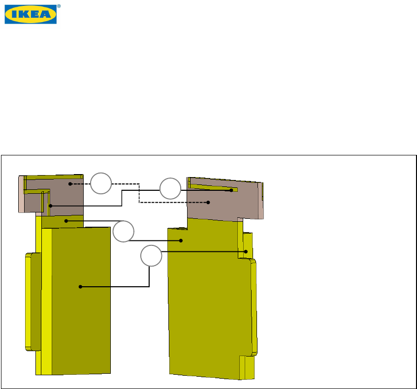
2 Design rules for antenna integration
The ICC-1 module can be integrated into various IKEA TRÅDFRI products. Follow the
described antenna integration design rules to ensure acceptable and correct radiated
performance. The antenna gain is -2.5dBi.
Figure 5 - Antenna area front and back of module
A
B
C
D
A Antenna area (free from
copper)
B Antenna
C PCB
D Component area
Document name: ICC-1 connectivity module Revision: 0.7
FCC ID: FHO-ICC-1 Revision date: 2016-07-05
IC ID: 10912A-ICC1
© Inter IKEA Systems B.V. 2016 Page 9 of 17
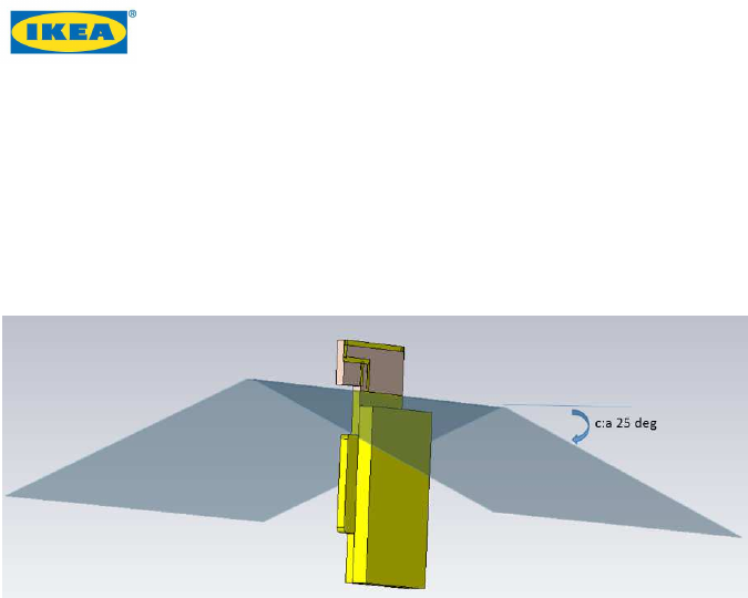
2.1 Distance to metal objects
Place large metal objects above the indicated surface as shown in Figure 6 and at least
30 mm from the antenna to secure antenna performance.
Figure 6 - Metal free area to secure antenna performance
2.2 Distance to plastic objects
Place large plastic objects at least 10 mm from the antenna. This can affect the
resonance frequency.
Document name: ICC-1 connectivity module Revision: 0.7
FCC ID: FHO-ICC-1 Revision date: 2016-07-05
IC ID: 10912A-ICC1
© Inter IKEA Systems B.V. 2016 Page 10 of 17
2.3 Grounding of metal heat sink
When using opening A in the solder mask of the Poly PCB as shown in Figure 7, the
antenna connection shall be as short and close to antenna feed as possible.
Figure 7 - Suggested grounding point
If integrated in LED bulbs, when inserted into an opening the module PCB shall be
grounded to the heatsink plate as shown in Figure 8.
Figure 8 - Grounding point for heatsink
Grounding point for heatsink
A
Document name: ICC-1 connectivity module Revision: 0.7
FCC ID: FHO-ICC-1 Revision date: 2016-07-05
IC ID: 10912A-ICC1
© Inter IKEA Systems B.V. 2016 Page 11 of 17
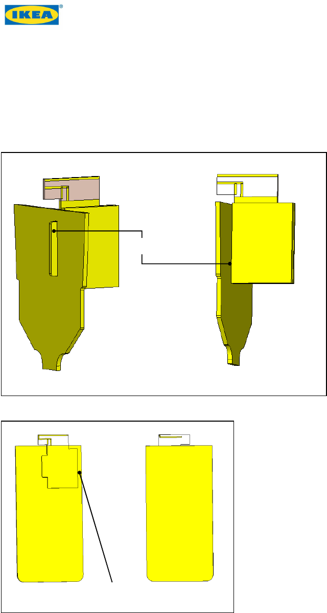
2.4 Module mounting options
If the ICC-1 module needs to be attached to another PCB during the integration process,
the connections shall be solid and stable to prevent unwanted effects on the antenna
performance. See Figure 10 and Figure 10 for possible attachment methods of the ICC-1
PCB to carrier board.
Figure 9 - Mounted 90 degree angle
Figure 10 - Flat board-to-board connection
2.4.1 Noisy signals
Keep potentially noisy traces and components of the motherboard as far as possible from
the antenna to prevent sensitivity of the module.
Soldered connection
Soldered connection

Document name: ICC-1 connectivity module Revision: 0.7
FCC ID: FHO-ICC-1 Revision date: 2016-07-05
IC ID: 10912A-ICC1
© Inter IKEA Systems B.V. 2016 Page 12 of 17
3 Power supply for ICC-1
3.1 Regulated power supply
ICC-1 can be supplied from a regulated power supply down to 1.85V in all conditions.
During peak load transients, power supply can be up to 145mA when using high power
mode. The product designer shall verify unconditional stability during peak load to
secure that voltage is not dropping below 1.85V.
The actual design of the regulator affects the decoupling capacity. Make sure that no
noise is injected via the power supply that impacts the analogue parts or the radio
supply.
3.2 Coin cell battery operation
ICC-1 can be operated from a single 3.0V coin cell battery. A minimum of sustaining
1.85V during all peak transients until battery end of life is required to guarantee proper
operation.
Make sure to fulfil the below requirements:
• Add enough decoupling to the device to avoid brown out during transient load in
TX burst. 20uF < 200uF.
• Limit output power to minimize peak power load.
• Schedule power consuming tasks to prevent tasks running parallel to minimize
peak load.
• Minimize over the air communication (OTA), time to perform tasks (like pairing),
fast poll, etc.
• Do not power the module via DCDC or other sources that have poor efficiency at
light loads.
Document name: ICC-1 connectivity module Revision: 0.7
FCC ID: FHO-ICC-1 Revision date: 2016-07-05
IC ID: 10912A-ICC1
© Inter IKEA Systems B.V. 2016 Page 13 of 17
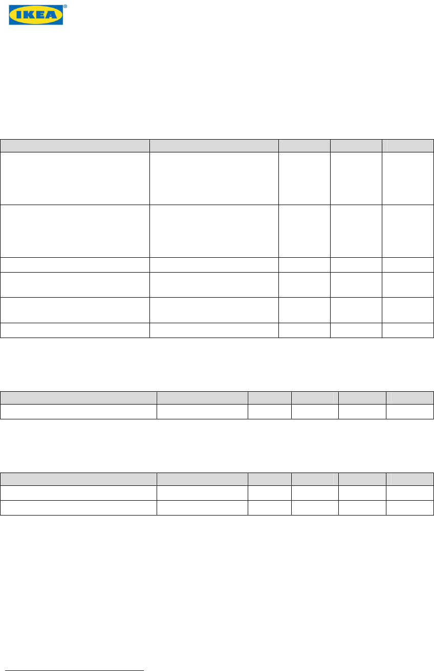
4 Electrical specifications
4.1 Absolute maximum ratings
Parameter Condition Min Max Unit
Ambient temperature range
-40 125
⁰C
Storage temperature
-50 150
⁰C
VDDMAX External voltage supply 0 3.35
1
V
VDIGPIN Voltage on any GPIO pin
except pin 2 and pin 3 -0.3 V
DD
+ 2 V
VLFXOPIN Voltage on pin 2 and pin 3 -0.3 V
DD
+
0.3 V
IIOMAX Current sink per I/O pin 0 50 mA
4.2 Recommended operating conditions
Parameter Condition Min Typ Max Unit
Operating supply voltage VREGVDD 1.62 3.3
1
3.35 V
4.3 Environmental
Parameter Condition Min Typ Max Unit
VESDHBM ESD HBM model 2 kV
VESDCDM ESD CDM model 500 V
1
Products using this module either uses battery with nominal voltage of 3.0V, or a regulated power at 3.3V or
lower.
Document name: ICC-1 connectivity module Revision: 0.7
FCC ID: FHO-ICC-1 Revision date: 2016-07-05
IC ID: 10912A-ICC1
© Inter IKEA Systems B.V. 2016 Page 14 of 17
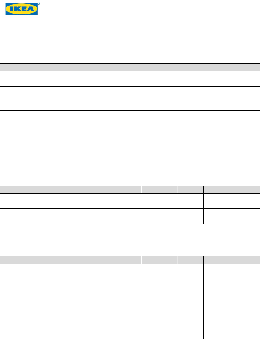
4.4 Transceiver characteristics
Parameter Condition Min Typ Max Unit
Maximum TX power, 802.15.4
DSSS-QPSK Conducted, 3.3V 14 dBm
RX Sensitivity 1% PER Conducted, 20 octets -99 dBm
FOFF Input frequency offset
tolerance 1% PER
-120 120 ppm
Co-channel interferer rejection
1% PER Received signal 10dB
above sensitivity level -3 dB
Adjacent channel rejection
5MHz Interferer +-1 channel
spacing 55 dB
Adjacent channel rejection
10MHz
Interferer +-2 channel
spacing
58 dB
4.5 Wake up timing
Parameter Condition Min Typ Max Unit
From EM2 deep sleep Executing RAM
or cache 2.8 3.4 uS
From EM2 deep sleep Executing from
flash 7.8 10.4 uS
4.6 General purpose input/output
Parameter Condition Min Typ Max Unit
VIOIL Input low voltage VDD*0.3
V
VIOIH Input high voltage VDDIO*0.7
V
VIOOL Output low voltage relative to
VDD VDD*0.4
V
VIOOH Output high voltage relative
to VDD
VDDIO*0.6
V
IIOLEAK Input leakage current 0.1 nA
RPU I/O pin pull-up resistor 30 40 50 kOhm
RPD I/O pin pull-down resistor 30 40 50 kOhm

Document name: ICC-1 connectivity module Revision: 0.7
FCC ID: FHO-ICC-1 Revision date: 2016-07-05
IC ID: 10912A-ICC1
© Inter IKEA Systems B.V. 2016 Page 15 of 17
5 Regulatory instructions
5.1 Limitations
ICC-1 shall only be installed in limb-worn devices and only be used as described in this
document and cannot be co-located with other antennas or transmitters, exceptionally if
specified in the grant condition of the equipment authorization. Other electronic
functions not associated with the certified module or certified transmitter requires
additional equipment authorization.
A host product itself is required to comply with all other applicable FCC equipment
authorization regulations, requirements, and equipment functions that are not associated
with the transmitter module portion. To ensure compliance for all non-transmitter
functions, a host product manufacturer is responsible for ensuring compliance with the
module(s) installed and fully operational.
ICC-1 fulfils the RF exposure requirements as portable limb-worn device and as mobile
device, with a separation distance equal to or more than 20 cm between product and
users body in normal operation.
ICC-1 must only be installed in portable limb-worn devices (not body worn) or in mobile
devices with a separation distance equal to or more than 20 cm from users body under
normal operations.
If ICC-1 is installed in a mobile device (host), a special text needs to be added in the
host user manual. This text needs to include information regarding the separation
distance and advise the end user that it is not allowed to be closer than 20 cm from the
device during normal operation. The text needs to be in both English and French
language.
5.2 User manual
User manual for license-exempt radio using the ICC-1 module needs to contain ICC-1
regulatory information.
5.3 Label
The label for license-exempt radio using the ICC-1 module shall be printed separately
and needs to contain the FCC ID/ISED certification number clearly visible on the product.

Document name: ICC-1 connectivity module Revision: 0.7
FCC ID: FHO-ICC-1 Revision date: 2016-07-05
IC ID: 10912A-ICC1
© Inter IKEA Systems B.V. 2016 Page 16 of 17
6 Certification
The ICC-1 module is certified with FCC ID: FHO-ICC-1 and Industry Canada IC: 10912A-
ICC1.
Caution: Changes or modifications not expressly approved by the party responsible for
compliance could void the user's authority to operate the equipment.
For more information, go to: http://www.ecfr.gov/cgi-bin/text-
idx?SID=a1be5f56bcd8d1391a26085ba51c6478&mc=true&node=se47.1.15_121&rgn=d
iv8.http://www.ecfr.gov/cgi-bin/text-
idx?SID=a1be5f56bcd8d1391a26085ba51c6478&mc=true&node=se47.1.15_121&rgn=d
iv8
6.1 FCC statement
This device complies with part 15 of the FCC Rules.
Operation is subject to the following two conditions:
(1) This device may not cause harmful interference, and
(2) This device must accept any interference received, including interference that may
cause undesired operation.
Note: This equipment has been tested and found to comply with the limits for a Class B
digital device, pursuant to part 15 of the FCC Rules.
These limits are designed to provide reasonable protection against harmful interference
in a residential installation.
This equipment generates, uses and can radiate radio frequency energy and, if not
installed and used in accordance with the instructions, may cause harmful interference to
radio communications.
However, there is no guarantee that interference will not occur in a particular
installation.
If this equipment does cause harmful interference to radio or television reception, which
can be determined by turning the equipment off and on, the user is encouraged to try to
correct the interference by one or more of the following measures:
• Reorient or relocate the receiving antenna.
• Increase the separation between the equipment and receiver.

Document name: ICC-1 connectivity module Revision: 0.7
FCC ID: FHO-ICC-1 Revision date: 2016-07-05
IC ID: 10912A-ICC1
© Inter IKEA Systems B.V. 2016 Page 17 of 17
• Connect the equipment into an outlet on a circuit different from that to which the
receiver is connected.
• Consult the dealer or an experienced radio/TV technician for help.
6.2 Industry Canada statement
This device complies with Industry Canada’s license-exempt RSSs.
Operation is subject to the following conditions:
(1)
This device may not cause interference; and
(2)
This device must accept any interference, including interference that may cause
undesired operation of the device.
(3)
Changes or modification not expressly approved by the partly responsible for
compliance could void the user’s authority to operate the equipment.
6.2.1 Avis d’industrie Canada
Le présent appareil est conforme aux CNR d'Industrie Canada applicables aux appareils
radio exempts de licence. L'exploitation est autorisée aux deux conditions suivantes:
(1) l'appareil ne doit pas produire de brouillage, et,
(2) l'utilisateur de l'appareil doit accepter tout brouillage radioélectrique subi, même si le
brouillage est susceptible d'en compromettre le fonctionnement.
(3) Tout changement ou modification non expressément approuvé par la partie
responsable de la conformité peut annuler le droit de l'utilisateur à utiliser l'équipement.