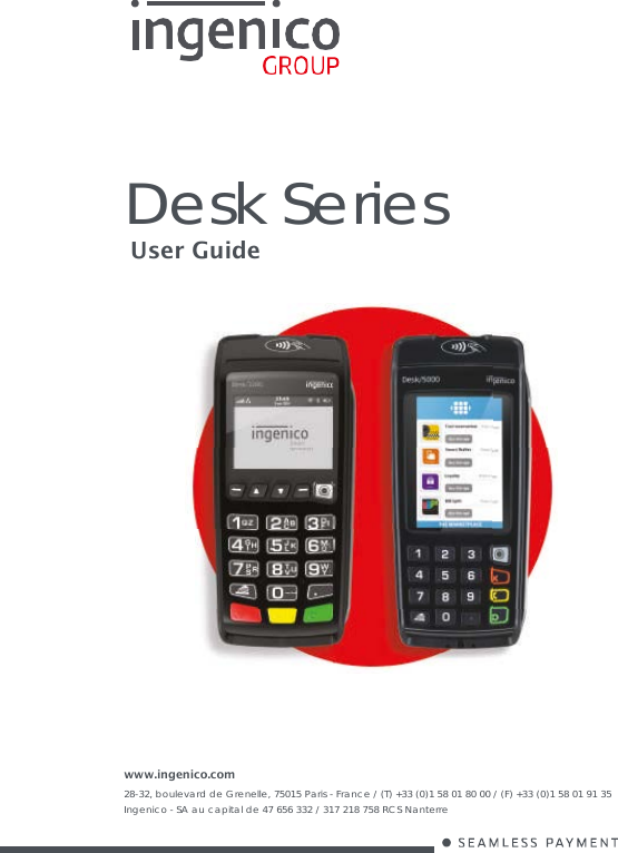
Ingenico D3500CLWI Standalone Payment Terminal User Manual User Guide

INGENICO Standalone Payment Terminal User Guide

User Guide

       Desk Series User Guide     www.ingenico.com 28-32, boulevard de Grenelle, 75015 Paris - France / (T) +33 (0)1 58 01 80 00 / (F) +33 (0)1 58 01 91 35 Ingenico - SA au capital de 47 656 332 / 317 218 758 RCS Nanterre
Desk Series 900024281 R11 000 05/1016 Copyright© 2016 Ingenico All rights reserved 2  Contents 1_Introduction     2_Unpacking     3_Recommendations     3_1 Safety / Sicherheit    3_1_1 Safety    3_1_2 Sicherheit    3_2 Telephone emergency, hanging up       3_3 Security of your terminal (tampering attempt detection)     3_4 Desk series : Fixed Installation     3_5 Characteristics    3_5_1 Main Characteristics    3_5_2 Haupteigenschaften    4_Installation   4_1 Positioning the terminal     4_2 Aufstellung des Terminals                   4_3 Connections     4_4 Installing the Terminal - Cable fixing    4_4_1 Kit Magic Box installation (optional)    4_5 Installing SAM (Secure access module)    4 5 13 6 6 8 13 6 7 8 9 10 10  11 13 14 15 17 20
Desk Series 900024281 R11 000 05/1016 Copyright© 2016 Ingenico All rights reserved 3  4_6 Installing MicroSD Card (optional) 4_7 Installing SIM for GPRS (optional)  4_8 Installing SAM3 (optional)     4_9 Installing 2nd SIM for GPRS (optional)    5_Installing a paper roll       6_Daily use       6_1 Keypad functions    6_2 Adjusting the contrast (B&W display only)    6_3 Card insertion    6_3_1 Swiping a card     6_3_2 Inserting a chip card     6_3_3 Reading Contacless (Optional)     6_3_4 Headphone output (Optional)    7_Maintenance / Wartung     7_1 Paper roll     7_2 Cleaning of the terminal     7_3 Transport and storage     7_4 Troubleshooting     7_5 Troubleshooting    8_Markings    8_1 FCC/IC Compliance    21 22 23 24 25 27 27 28 28 28  28  28 30 30 30 31 32 32 33 33 35
Desk Series 900024281 R11 000 05/1016 Copyright© 2016 Ingenico All rights reserved 4  1_Introduction Thank you for choosing an Ingenico payment terminal.  We recommend you to read carefully this user guide: It gives you the necessary information about safety precautions, unpacking, installation, and maintenance of your terminal.  WARRANTY / SECURITY To benefit from the guarantee-related product, and to respect the security, we ask you to use only the power supply delivered in box with the product, entrusting maintenance operations only to an authorized person. Failure to comply with these instructions will void the manufacturer’s responsibility.  GARANTIE / SICHERHEIT Um bestmöglich von dem garantierten Produkt zu profitieren und die Sicherheitsbedingungen zu gewährleisten, bitten wir Sie ausschließlich das der Verpackung beiliegende Netzteil zu benutzen und ausschließlich befugte Personen mit der Wartung zu beauftragen. Bei Nichtbeachtung dieser Anweisung erlischt die Haftbarkeit des Herstellers.  This symbol indicates an important Warning.   Dieses Symbol weist auf eine wichtige Warnung.   This symbol indicates a piece of advice.
Desk Series 900024281 R11 000 05/1016 Copyright© 2016 Ingenico All rights reserved 5  2_Unpacking According to the model, the following items are included in the packaging box (including optional accessories): The terminal equipped with its paper roll The power supply with its cable connection (according to the national needs). The cable connection for the telephone or Ethernet network This installation guide  User guide   Wall mounted power supply unit  Cable connection for the telephone or Ethernet network       Terminal  Desktop power supply unit required if terminal is fitted with the following options: Radio model (all) Contactless model   CAUTION The power supply unit provided with your equipment is specially designed for it. Do not use any other power supply.   WARNHINWEIS Bitte verwenden Sie ausschließlich das mitgelieferte Netzteil, kein anderes Netzteil.
Desk Series 900024281 R11 000 05/1016 Copyright© 2016 Ingenico All rights reserved 6    ADVICE Keep the packaging. It must be re-used whenever the terminal is shipped.  3_Recommendations 3_1 Safety / Sicherheit 3_1_1 Safety Power on/Power down – Emergency stop To power on or power down the terminal connect or disconnect the power supply from the electric outlet. Lithium battery cell The terminal is fitted with a lithium battery cell which is not accessible to the user. Only a qualified technician is authorized to open the unit and change this component. Electrical power supply network The electrical outlet must meet the following criteria: Must be installed near the equipment and easily accessible; Must meet standards and regulations in the country of use; For type A plug, the protection of the installation must be set to 20 A. Except for Norway do not connect on an IT electrical network. Telephone network The phone network must comply with standards and regulations in the country of use Explosion areas Certain  regulations  restrict  the  use  of  radio  equipment  in  chemical plants, fuel depots and any site where blasting is carried out. You are urged to comply with these regulations. The terminal shall be protected by a specially fitted and certified cover enabling use in proximity to a fuel pump. Electronic health appliances According to the model your terminal could be a radio transmitter which may interfere with health appliances, such as hearing aids, pacemaker, hospital equipment, etc. Your doctor or the equipment manufacturer will be able to provide you with appropriate advice.
Desk Series 900024281 R11 000 05/1016 Copyright© 2016 Ingenico All rights reserved 7  Bottom side compartment trapdoor Located under the terminal, it must be in place during normal operation of the terminal. Le réseau téléphonique doit être conforme aux normes et réglementations en vigueur dans le pays d’utilisation.  3_1_2 Sicherheit Power ein/Power aus – Nothalt Zum Ein-oder Ausschalten der Klemme stecken oder ziehen Sie das Netzkabel aus der Steckdose. Lithium-Batterie Das Terminal ist mit einer Lithiumbatterie ausgestattet, die für den Benutzer unzugänglich ist. Nur ein qualifizierter Techniker sollte die Box zu öffnen, um die Komponente zu ersetzen. Anschluss an das Stromnetz Die Steckdose muss die folgenden Kriterien erfüllen: In der Nähe des Geräts befinden und leicht zugänglich Erfüllt die Normen und Vorschriften im Einsatzland Typ-A Stecker müssen mit 20A abgesichert sein. Mit Ausnahme von Norwegen nicht an ein IT-Stromnetz anschließen. Telefonnetz Einen Telefonstecker gemäß den Normen und Vorschriften des Benutzerlandes bereitstellen. Explosionsgefährdung Einige Vorschriften beschränken den Einsatz von Funkgeräten in   Chemieanlagen,   Kraftstofflagern   und   anderen   Standorten   mit Explosionsgefahr. Sie werden gebeten, diese Vorschriften einzuhalten. Das Terminal muss durch eine Abdeckung geschützt werden, die für den Einsatz in der Nähe einer Kraftstoffpumpe speziell entwickelt und zertifiziert ist. Elektronik Gesundheit Je nach Modell, könnte Ihr Gerät ein Funksender sein, der medizinische Gerste wie Hörgeräte, Herzschrittmacher, Krankenhausausrüstung, usw. stören kann. Ihr Arzt oder der Hersteller ist in der Lage, Sie entsprechend zu beraten. Die untere Gehäuseabdeckung Sie befindet sich unter dem Terminal und muss bei normalem Terminalbetrieb angebracht sein.
Desk Series 900024281 R11 000 05/1016 Copyright© 2016 Ingenico All rights reserved 8  3_2 Telephone emergency, hanging up You have an urgent call to make, when terminal hangs on the line. Perform as follow in order to get a dial tone… Place the handset in the hang up position and: Press the red key (=cancel) Or disconnect the power supply from the mains Or disconnect the terminal telephone connector from the telephone line socket, and place the telephone connector into the telephone line socket. You will get a dial tone within 6 seconds. 3_3 Security of your terminal (tampe- ring attempt detection) Your device fulfils current applicable PCI PTS security requirements. Upon receipt of your terminal you should check for signs of tampering of the equipment. It is strongly advised that these checks are performed regularly after receipt. You should check, for example: that the keypad is firmly in place; that there is no evidence of unusual wires that have been connected to any ports on your terminal or associated equipment, the chip card reader, or any other part of your terminal. Such checks would provide warning of any unauthorized modifications to your terminal, and other suspicious behavior of individuals that have access to your terminal. Your terminal detects any “tampered state”. In this state the terminal will repeatedly flash the message” Alert Irruption!” and further use of the terminal will not be possible. If you observe the “Alert Irruption!” message, you should contact the terminal helpdesk immediately. You are strongly advised to ensure that privileged access to your terminal is only granted to staff that have been independently verified as being trustworthy. The terminal must never be put in or left at a location where it could be stolen or replaced by another device. Your device is also available with PCI PTS compliant pin-shield:
Desk Series 900024281 R11 000 05/1016 Copyright© 2016 Ingenico All rights reserved 9    CAUTION Positioning of the terminal on check stand must be in such a way to make cardholder PIN (Personal Identification Number) spying infeasible. Installing device on an adjustable stand must be in such a way that consumers can swivel the terminal sideways and/or tilt it forwards/backwards to a position that makes visual observation of the PIN-entry process difficult. Positioning of in-store security cameras such that the PIN-entry keypad is not visible. NEVER ask the customer to divulge their PIN Code. Customers should be advised to ensure that they are not being overlooked when entering their PIN Code. 3_4 Desk series : Fixed Installation If the device is to be used in a situation where it is not possible for the cardholder to pick up and shield their PIN entry themselves, the device may be used without PIN shield, but it must be installed in the following manner: a) The device must be angled at 45 or more, so that oversight of the PIN entry from the rear of the device is not possible. b) The device must either be fitted in a swivel stand –  so that the customer can position the device in the best angle to prevent oversight – or the device must be fixed in the best possible position to prevent oversight if such a generic position exists in the specific environment to which the device is installed. c) The device environment must be accompanied with conspicuous notices and educational material which informs the customer to shield their PIN during PIN entry. d) The device must be deployed so that oversight from other customers, either in different payment lanes, or in other areas of the shopping environment, is prevented. This may be achieved through the placement of the lanes and device , so that the customer is automatically positioned between the device keypad and other customers. Alternatively, it may be achieved by the environment in which the device is installed, so that the checkout itself shields the PIN entry process. e) The terminal is  exclusively  made  for indoor use If the above conditions are not fulfilled, the device with PIN shield must be used.
Desk Series 900024281 R11 000 05/1016 Copyright© 2016 Ingenico All rights reserved 10  3_5 Characteristics / Haupteigenschaften 3_5_1 Main Characteristics Terminal  Weight (w/o paper roll) about 310 g to 340 g full option  Size 187 x 82 x 68 mm (l x w x h) Power supply unit (wall mounted)  Weight approx 115 g  Size approx 77 x 25 x 89 mm (L x w x h) Class Class II equipment Input voltage AC 230V 50-60Hz Output voltage DC 8V 2A 3A Desktop power supply unit  Weight approx 191 g (without mains cable)  Size approx 118 x 48 x 31 mm (L x w x h) Class Class II equipment Input voltage AC 100-240V 50-60Hz Output voltage DC 8V 3A The power supply unit is especially designed by the manufacturer for its terminal with contactless function, do not use another one. 4A Desktop power supply unit  Weight approx 230 g (without mains cable)  Size approx 115 x 52 x 32 mm (L x w x h) Class Class II equipment Input voltage AC 115-230V 50-60Hz Output voltage DC 8V 4A The power supply unit is especially designed by the manufacturer for its terminal with radio transceivers, do not use another one.
Desk Series 900024281 R11 000 05/1016 Copyright© 2016 Ingenico All rights reserved 11  Accordance terminal / type of power supply  Label on terminal Type power supply  8V 2A Plug power supply (wall mounted) (Output 2A) Recommended for terminals without any Radio transceivers (ie : Ethernet/Modem). 8V 3A Desktop power supply (Output 3A) Recommended for terminals with Contactless  8V 4A Desktop power supply (Output 4A) Recommended for terminals with Radio transceivers (2G, 3G, Wifi, Bluetooth) Cable length  Label on terminal Type power supply (wall mounted)  Power block cable approx 1,8 m Telephone cable approx 3 m   3_5_2 Haupteigenschaften  Terminal  Gewicht 310 g bis 340 g bei allen Optionen  Größe 187 x 82 x 68 mm (L x B x H)  Netzteil (an der Wand angebracht)  Gewicht ungefähr 115 g (ohne Netzkabel)  Größe ungefähr 75 x 25 x 89 mm (L x B x H) Klasse Ausrüstung Klasse II Eingangsspannung AC 230V 50-60Hz Ausgangsspannung DC 8V 2A
Desk Series 900024281 R11 000 05/1016 Copyright© 2016 Ingenico All rights reserved 12  3A Büronetzadapter  Gewicht ungefähr 191 g (ohne Netzkabel)  Größe ungefähr 118 x 48 x 31 mm (L x B x H) Klasse Ausrüstung Klasse II Eingangsspannung AC 100-240V 50-60Hz Ausgangsspannung DC 8V 3A Der Netzteil wurde speziell vom Hersteller für seine Terminals entworfen und muss mit diesen benutzt werden.  4A Büronetzadapter  Gewicht ungefähr 230 g (ohne Netzkabel)  Größe ungefähr 111 x 52 x 32 mm (L x B x H) Klasse Ausrüstung Klasse II Eingangsspannung AC 115-230V 50-60Hz Ausgangsspannung DC 8V 4A Der Netzteil wurde speziell vom Hersteller für seine Terminals entworfen und muss mit diesen benutzt werden.  Dazugehöriges Terminal / Netzteiltyp  Label terminal Netzteiltyp   8V 2A Plug Netzadapter (Befestigung an der Wand) (OUTPUT 8V 2A) oder Büronetzadapter (OUTPUT 8V 4A) 8V 3A Büronetzadapter (OUTPUT 8V 3A) 8V 4A Büronetzadapter (OUTPUT 8V 4A)  Kabellänge Netzteilkabel Telefonkabel ungefähr 1,8 m ungefähr 3 m
Desk Series 900024281 R11 000 05/1016 Copyright© 2016 Ingenico All rights reserved 13  4_Installation 4_1 Positioning the terminal Install the terminal on a flat surface, with an easy access to an electrical outlet and telephone line. Place the terminal away from any heat source and protected from dust, vibrations and electromagnetic radiations (away from video terminals, PC, anti-shoplifting barriers, ...). The terminal is exclusively made for indoor use. Operating conditions  Ambient temperature from 0°C to +40°C  Max relative humidity 85% at +40°C Max altitude 2000 m Storage conditions  Storage temperature -20°C, +55°C  Max relative humidity 85% at +55°C  4_2 Aufstellung des Terminals Stellen Sie das Terminal auf eine flache Oberfläche mit einfachem Zugang zu einer Netzsteckdose und Telefonleitung. Stellen Sie das Terminal nicht in der Nähe von Wärmequellen auf und schützen Sie es vor Staub, Vibrationen und elektromagnetischen Strahlungen (weit entfernt von Videoterminals, PCs, Diebstahlschranken, etc.) Betriebsbedingungen  Umgebungstemperatur 0°C bis +40°C  Maximale Luftfeuchtigkeit 85% bei +40°C Maximale Höhe 2000 m Lagerbedingungen  Lagertemperatur -20°C, +55°C  Maximale Luftfeuchtigkeit 85% bis +55°C
Desk Series 900024281 R11 000 05/1016 Copyright© 2016 Ingenico All rights reserved 14  4_3 Connections All connections are on the rear of the terminal protected by a down side trapdoor.    Telephone (Optional)*  Power Supply   µSD (Optional)* SIM 1 & 2 (Optional)* Serial Link RS232 Ethernet Link (Optional)* 10/100 BaseT USB Host USB Host/ Slave 2nd Serial Link RS232 (Optional)*   SAM 1 & 2 SAM 3 (Optional)*  *according to the model   Phone : TNV-3. Power Supply : Limited Power Source. Other connections : Safety Extra-low Voltage. According to IEC60950-1 and EN60950-1
Desk Series 900024281 R11 000 05/1016 Copyright© 2016 Ingenico All rights reserved 15  4_4 Installing the Terminal - Cable fixing Opening down-side trapdoor Unclip the trapdoor by pushing on the clip       with your finger as shown on the figure here below. Then lift the trapdoor rearward to remove it, as shown by arrows    on the figure          Closing down-side trapdoor To close the trapdoor, start by landing trapdoor on to bottom casing as shown on the figure  , manage 5/6mm distance for clip insertion then push and clip it.
Desk Series 900024281 R11 000 05/1016 Copyright© 2016 Ingenico All rights reserved 16  Connecting cables  WARNING Connecting is to be made when the terminal is powered off.   WARNHINWEIS Die Anschlüsse müssen bei ausgeschaltetem Terminal erfolgen.  Perform the following operations:  Open down side trapdoor then unclips the cables hook     Plug telephone line , equipped if necessary with user country specific converter , to the telephone network (*). Connect the other end to the terminal telephone connection . If necessary, connect the telephone (Telephone is not required for the terminal to operate)  Optionally plug others cables (Ethernet, RS232, USB…) Plug PSU power lead into the power socket  .
Desk Series 900024281 R11 000 05/1016 Copyright© 2016 Ingenico All rights reserved 17  Clips  the  cables-hook  part  to  secure  cables  path  then  close down side trapdoor  (*): TNV-3 circuit: Telecommunication Network Voltage, as per safety standard EN 60950-1.    4_4_1 Kit Magic Box installation (optional) WARNING Connecting is to be made when the terminal is powered off.   WARNHINWEIS Die Anschlüsse müssen bei ausgeschaltetem Terminal erfolgen. Plug the power supply into the mains. For instance, possible configuration for France
Desk Series 900024281 R11 000 05/1016 Copyright© 2016 Ingenico All rights reserved 18  Perform operations as described in “connecting cables” chapter and connect cables as follow: Cables to plug: Power lead Telephone line Ethernet cable Serial link RS232 cable   If you need extra cables then cut undesired over-molded section at  Install through-holes in the lead-through guides (as indicated on the figure).
Desk Series 900024281 R11 000 05/1016 Copyright© 2016 Ingenico All rights reserved 19   ADVICE It is strongly recommended to secure the “Magic cable” to terminal’s  work area in order to reduce stress on terminal and connection.     Using the supplied cable tie to attach to a table leg (or similar)    Using the supplied cable tie and self-adhesive support   Using a counter-sunk screw (not supplied) to an appropriate surface  The  “Magic  Cable”  should  be  readily  accessible  for  terminal maintenance and helpdesk diagnosis purposes.  NOTE: The connection Magic Box can also be attached using a VELCRO™ or other system.
Desk Series 900024281 R11 000 05/1016 Copyright© 2016 Ingenico All rights reserved 20  4_5 Installing SAM (Secure access module)  CAUTION Before starting, switch off the terminal by disconnecting the power supply.  WARNHINWEIS Bevor Sie beginnen, das Gerät auszuschalten, indem Sie das Netz.  Perform the following operations: Open down side trapdoor Insert the SAM Card into the slot marked (1) or (2). Take care to ensure that the SAM Card is inserted in the correct manner. The cut corner must be positioned as indicated on the figure.  Cut corner              Close down side trapdoor We suggest you to use a piece of adhesive previously pasted on both sides of the SAM as shown here below for easy removal
Desk Series 900024281 R11 000 05/1016 Copyright© 2016 Ingenico All rights reserved 21  Cut corner   Adhesive   CAUTION Do not use any tools when installing or removing the SAM Card.  WARNHINWEIS Zum Einsetzen oder Entfernen der SAM Karte keinerlei Werkzeug benutzen.  4_6 Installing MicroSD Card (optional) CAUTION Before starting, switch off the terminal by disconnecting the power supply.  WARNHINWEIS Bevor Sie beginnen, das Gerät auszuschalten, indem Sie das Netz.  Perform the following operations: Open down side trapdoor Insert completely the MicroSD Card into the slot marked (MicroSD) as indicated on the figure. MicroSD Card must be back side positioned as indicated on marking. To remove the MicroSD Card push on it with touch panel pencil. Close down side trapdoor
Desk Series 900024281 R11 000 05/1016 Copyright© 2016 Ingenico All rights reserved 22    4_7 Installing SIM for GPRS (optional) CAUTION Before starting, switch off the terminal by disconnecting the power supply.  WARNHINWEIS Bevor Sie beginnen, das Gerät auszuschalten, indem Sie das Netz. Open down side trapdoor    Cut corner     Insert the SIM GPRS into the slot marked (SIM1) as indicated on the figure. Take care to ensure that the SIM is inserted in the correct manner. The cut corner must be positioned as indicated on the figure. Close down side trapdoor.
Desk Series 900024281 R11 000 05/1016 Copyright© 2016 Ingenico All rights reserved 23  4_8 Installing SAM3 (optional)  CAUTION Before starting, switch off the terminal by disconnecting the power supply.  WARNHINWEIS Bevor Sie beginnen, das Gerät auszuschalten, indem Sie das Netz.  Open down side trapdoor Insert the SAM Card into the slot marked (3) as indicated on the figure. Take care to ensure that the SIM is inserted in the correct manner. The cut corner must be positioned as indicated on the figure.       Cut corner         Close down side trapdoor.
Desk Series 900024281 R11 000 05/1016 Copyright© 2016 Ingenico All rights reserved 24  4_9 Installing 2nd SIM for GPRS (optional) CAUTION Before starting, switch off the terminal by disconnecting the power supply.   WARNHINWEIS Bevor Sie beginnen, das Gerät auszuschalten, indem Sie das Netz. Open down side trapdoor nsert the SIM GPRS into the slot marked (SIM2) as indicated on the figure. Take care to ensure that the SIM GPRS is inserted in the correct manner. The insertion position SIM corner (engraved on the terminal) must be located as shown on figure.     Cut corner       Do not force at the insertion. Once positioned the SIM GPRS is not fully inserted, this is normal.   Nicht mit Gewalt einzusetzen. Nach der Positionierung der GPRS-SIM-Karte wird den ganzen Weg, was normal ist nicht eingelegt.  Close down side trapdoor
Desk Series 900024281 R11 000 05/1016 Copyright© 2016 Ingenico All rights reserved 25  5_Installing a paper roll Your terminal is supplied with one paper roll. When the paper roll is nearing the end, a red line will appear on the paper; this indicates that the paper roll must be replaced.  CAUTION Use only paper approved by the manufacturer (diameter 40 mm). Use of unsuitable paper is likely to damage the printer of your terminal (see paper characteristics at “Maintenance” chapter).  WARNHINWEIS Nur vom Hersteller zugelassenes Papier benutzen (Durchmesser 40 mm). Durch den Einsatz von ungeeignetem Papier kann der Drucker des Terminals beschädigt werden (Siehe die Papierspezifikationen in Kapitel «Wartung»).  Open the paper compartment by lifting the catch located at the rear of the terminal and drag the cover to the rear.   CAUTION Do not force the cover against the cables.  WARNHINWEIS Die Abdeckungen nicht gegen die Kabel drücken.
Desk Series 900024281 R11 000 05/1016 Copyright© 2016 Ingenico All rights reserved 26  Insert the paper roll in the compartment following the directions shown on the figure below. Pull the paper up to the top of the terminal and hold it in this position. Maintain the paper and close the lid. Press the top of the lid in the centre as shown by arrow, until it clips into position.   ADVICE If you are inserting a new paper roll remove the first complete turn (this first turn of sensitive surface could be damaged during shipment).
Desk Series 900024281 R11 000 05/1016 Copyright© 2016 Ingenico All rights reserved 27  6_Daily use 6_1 Keypad functions    NAVIGATION keys  Ingenico key  CANCEL key (red)  CLEAR key (yellow) / Feed paper (long press)   VALIDATION key (green) Dot key
Desk Series 900024281 R11 000 05/1016 Copyright© 2016 Ingenico All rights reserved 28  6_2 Adjusting the contrast (B&W display only) No contrast management for the Color display If you wish to increase or to decrease the contrast of the characters displayed on screen, press simultaneously on the  (dot key) and key to decrease the contrast, or the  (dot key) key to increase it. Keep pressing the keys as long as necessary.  6_3 Card insertion 6_3_1 Swiping a card  Insert the card manually in the driver, magstripe facing the main body of the terminal.     Swipe the card with constant speed, not too slowly not too fast, to maximize the reading efficiency and avoid annoying repetitions.   6_3_2 Inserting a chip card Chip   Cards   should   be   inserted   into   your terminal as illustrated with the chip facing up and into the card reader.
Desk Series 900024281 R11 000 05/1016 Copyright© 2016 Ingenico All rights reserved 29  6_3_3 Reading Contactless (Optional)  Bring the card firmly up to the active zone above (at about 1cm) the contactless logo located on paper trapdoor button. Keep the card close to the contactless logo during the transaction Your contactless terminal provides four contactless status lights located on display/ lens.  When a contactless transaction is started the first (left hand) status light will be lit steadily; this indicates that the contactless is in use but a card is not being read.  When a contactless card is presented to the contactless active zone (*)  during a transaction the second, third and fourth status lights will be lit in turn. The card read is successful when all four status lights are lit and a confirmation tone can be heard.  Contactless Status lights (*): Contactless Symbol is a trademark owned by and used with the permission of EMVCo, LLC.  CAUTION Do not stick any conductive label on to contactless active zone located on paper trapdoor button. It can decrease seriously contactless efficiency.   WARNHINWEIS Keine leitende Etikett Kleben Sie nicht an kontaktlosen aktiven Zone auf Papier Falltür-Taste befindet. Es kann ernsthaft kontakt Effizienz verringern. Contactless Active zone
Desk Series 900024281 R11 000 05/1016 Copyright© 2016 Ingenico All rights reserved 30  6_3_4 Headphone output (Optional) The headphone output jack is located under the card reader outlet. This option is not designed to play music, but to facilitate the use by blind people. Die  Kopfhörerbuchse  ist  unter  der  Chipkartenleser  entfernt.  Diese Option ist nicht für die Musik zu spielen, aber nur, um die Verwendung von blinden Menschen zu erleichtern. 7_Maintenance / Wartung  CAUTION Before making any operations of maintenance in the terminal, make sure that the power supply is disconnected.   WARNHINWEIS Bevor irgendwelche Operationen der Wartung im Terminal, stellen Sie sicher, dass die Stromversorgung getrennt wird. 7_1 Paper roll   Characteristics Precisions  Colour White Width 58 mm Diameter 40 mm max.    The thermal paper can be deteriorated by poor storage conditions, so we recommend you to avoid: storage in hot wet places (near to air-conditioner, humidity higher than 85%) exposure to sunlight or ultraviolet for long periods contact with organic solvents (solvent type adhesive)
Desk Series 900024281 R11 000 05/1016 Copyright© 2016 Ingenico All rights reserved 31  direct contact with materials containing plasticizers (PVC transparent folders or envelopes) direct contact with «diazo» papers direct contact with water Rubbing or pressing the paper too strongly CAUTION In order to benefit from the complete guarantee of the product, use manufacturer approved thermal paper only.  WARNHINWEIS Um in den vollen Genuss der Garantie zu kommen, darf nur vom Hersteller zugelassenes wârmeempfindliches Papier benutzt werden. 7_2 Cleaning of the terminal First of all, unplug all the wires from the terminal. Good rules for proper cleaning of the terminal are: Use a soft cloth that is very slightly soaked with soapy water to clean the outside of the terminal. Manufacturer wipes kit is strongly recommended (ref: 296118801). Do not clean the electrical connections.  CAUTION Do not use in any case, solvents, detergents or abrasive products: Those materials might damage the plastic or electrical contacts.  WARNHINWEIS In jedem Fall, verwenden Sie keine Lösungsmittel, Reinigungsmittel oder Scheuermittel: Diese Materialien können Kunststoff-oder elektrische Kontakte beschädigen.
Desk Series 900024281 R11 000 05/1016 Copyright© 2016 Ingenico All rights reserved 32  Avoid exposing the terminal to the direct rays of the sun. Do not put anything into the slot of the smart card reader 7_3 Transport and storage Use the original packaging for any unit or stored. Disconnect all cables from the terminal during the transport. 7_4 Troubleshooting The terminal does not turn on or does not connect to the telephone line Check the power supply and telephone line cables Check for electrical power network  The terminal fails to establish a telephone connection Check that the tone of the phone line is free Check the configuration of the phone line and number to call Get support from technical Cards are not read Check that the magnetic card is passed correctly (with magstripe facing the main body of the terminal) Swipe again the card with with constant speed, not too slow not too fast. Verify that the magnetic strip is not damaged, grooved or cracked Make sure you have inserted correctly the smart card into the smart card reader and removed the card only after the transaction  The ticket is not printed Check the presence and proper positioning of the paper roll. Possibly adjust the paper roll following instructions present in this manual Check the type of paper used (thermal paper must be used) Verify thermal paper sensitive side.
Desk Series 900024281 R11 000 05/1016 Copyright© 2016 Ingenico All rights reserved 33  7_5 Environment (WEEE, Batteries and Packaging) This product is labeled in accordance with European Directives 2002/96/EC concerning Waste Electrical and Electronic Equipment (WEEE) and 2006/66/EC concerning Batteries and Accumulators. Those provisions are requiring producers and manufacturers to become liable for take-back, treatment and recycling upon end of life of equipment and batteries.  The associated symbol means that WEEE and waste batteries must not be thrown away but collected separately and recycled.  Ingenico ensures that efficient collection and recycling schemes are set-up for WEEE and batteries according to the local regulation of your country. Please contact your retailers for more detailed information about the compliance solution in place for disposing of your old product and used batteries. Packaging waste must also be collected separately to assure a proper disposal and recycling. Please note that proper recycling of the electrical and electronic equipment and waste batteries will ensure safety of human health and environment 8_Markings The CE marking indicates terminal complies with harmonized standards and requirements of European Directives on: Radio and Telecommunications Terminal Equipment (R&TTE) RoHS (Restriction of Hazardous Substances) Dieses    Produkt,    mit    der    CE-Kennzeichnung    , entspricht: dereuropäischenRichtlinieüberFunkanlagen und Telekommunikationsendeinrichtungen (R&TTE). der europäischen Richtlinie über die Beschränkung der Verwendung bestimmter gefährlicher Stoffe (RoHS).
Desk Series 900024281 R11 000 05/1016 Copyright© 2016 Ingenico All rights reserved 34  This marking indicates that the product operates with an alternating current (AC) source (mains). It is     completed by afferent values (voltage, frequency and max current). This marking indicates that your terminal is suitable for direct current (DC) only. It is completed by afferent values (voltage, and max current).   This marking indicates power supply meets the energy efficiency level VI requirements.     Marking for Class II product. Such product does not require a safety connection to electrical earth.     For Indoor use only.   Output plug is Positive (+) and the barrel (ring) of      the output plug is Negative (-) This marking indicates power supply meets limited power source safety requirements.   This marking is apposed on to connector for telephone line connection.    This marking is apposed on to connector for power supply output cable connection.
Desk Series 900024281 R11 000 05/1016 Copyright© 2016 Ingenico All rights reserved 35  8_1 FCC/IC Compliance  Model Name FCC ID IC NUMBER Model : DESK/5000 Eth/Mod FCC ID : XKB-D5000M00 IC : 2586D-D5000M00 Model : DESK/5000 CL/Eth/Mod FCC ID : XKB-D5000M01 IC : 2586D-D5000M01 Product : DESK/5000 CL/Eth/Mod/WiFi/BT FCC ID : XKB-D5000 CLWIBT IC : 2586D-D5000CLWIBT Product : DESK/3200 CL/Eth/Mod FCC ID : XKB-D3200CL IC : 2586D-D3200CL Product : DESK/3500 CL/Eth/Mod FCC ID : XKB-D3500CL IC : 2586D-D3500CL Product : DESK/3500 CL/Eth/Mod/WiFi FCC ID : XKB-D3500CLWI IC : 2586D-D3500CLWI     This equipment has been tested and found to comply with the limits for a Class B digital device, pursuant to part 15 of the FCC Rules. These limits are designed to provide reasonable protection against harmful interference in a residential installation. This equipment generates, uses and can radiate radio frequency energy and, if not installed and used in accordance with the instruction, may cause harmful interference to radio communications. However, there is no guarantee that interference will  not  occur in a particular installation. If this equipment does cause harmful interference to radio or television reception which can be determined by turning the equipment off and on, the user is encouraged to try to correct interference by one or more of the following measures : Reorient or relocate the receiving antenna. Increase the separation between the equipment and receiver. Connect the equipment into an outlet on circuit different from that to which the receiver is connected. Consult the dealer or an experienced radio/TV technician for help.
Desk Series 900024281 R11 000 05/1016 Copyright© 2016 Ingenico All rights reserved 36     This device complies with Part 15 of the FCC Rules and Industry Canada license-exempt RSS standard(s). Operation is subject to the following two conditions: (1) This device may not cause harmful interference, and (2) This device must accept any interference received, including interference that may cause undesired operation.    Le  présent  appareil  est  conforme  aux  CNR  d’Industrie  Canada applicables aux appareils radio exempts de licence. L’exploitation est autorisée aux deux conditions suivantes : (1) l’appareil ne doit pas produire de brouillage, et (2) l’utilisateur  de  l’appareil  doit  accepter  tout  brouillage radioélectrique subi, même si le brouillage est susceptible d’en compromettre le fonctionnement. Under Industry Canada regulations, this radio transmitter may only operate using an antenna of a type and maximum (or lesser) gain approved for the transmitter by Industry Canada. To reduce potential radio interference to other users, the antenna type and its gain should be so chosen that the equivalent isotropically radiated power (e.i.r.p.) is not more than that necessary for successful communication. Conformément à la réglementation d’Industrie Canada, le présent émetteur radio peut fonctionner avec une antenne d’un type et d’un  gain  maximal  (ou  inférieur)  approuvé  pour  l’émetteur  par Industrie Canada. Dans le but de réduire les risques de brouillage radioélectrique   à   l’intention   des   autres   utilisateurs,   il   faut choisir le type d’antenne et son gain de sorte que la puissance isotrope rayonnée équivalente (p.i.r.e.) ne dépasse pas l’intensité nécessaire à l’établissement d’une communication satisfaisante. This device complies with FCC RF and Industry Canada RF radiation exposure limits set forth for general population. This device must be installed to provide a separation distance of at least 20cm from all persons and must not be co-located or operating in conjunction with any other antenna or transmitter. Le présent appareil est conforme aux niveaux limites d’exigences d’exposition  RF  aux  personnes  définies  par  Industrie  Canada. L’appareil doit être installé afin d’offrir une distance de séparation d’au moins 20cm avec l’utilisateur, et ne doit pas être installé à proximité ou être utilisé en conjonction avec une autre antenne ou un autre émetteur. No changes shall be made to the equipment without the permission of Ingenico as this may void the user’s authority to operate the equipment.
Desk Series 900024281 R11 000 05/1016 Copyright© 2016 Ingenico All rights reserved 37  Tout changement apporté à ce terminal non expressément approuvé  par  Ingenico  est  susceptible  d’annuler  le  droit  de l’utilisateur à se servir de cet équipement. This product meets the applicable Innovation, Science and Economic Development Canada technical specifications. The Ringer Equivalence Number (REN) indicates the maximum number of devices allowed to be connected to a telephone interface. The termination of an interface may consist of any combination of devices subject only to the requirement that the sum of the RENs of all the devices not exceed five. REN for this device is 0.1. Le présent appareil est conforme aux spécifications techniques applicables d’Innovation, Sciences et Développement économique  Canada.  L’indice  d’équivalence  de  la  sonnerie  (IES) sert à indiquer le nombre maximal de dispositifs qui peuvent être raccordés à une interface téléphonique. La terminaison d’une interface peut consister en une combinaison quelconque de dispositifs, à la seule condition que la somme des IES de tous les dispositifs n’excède pas cinq. L’IES pour cet appareil est de 0.1.  Part 68 of FCC Rules Model Name US MODEM  Model : DESK/5000 Eth/Mod US : IEOMM01BD5000M00 Model : DESK/5000 CL/Eth/Mod US : IEOMM01BD5000M01 Product : DESK/5000 CL/Eth/Mod/ Wifi/BT US : IEOMM01BD5000M01 Product : DESK/3200 CL/Eth/Mod US : IEOMM01BD3200CL Product : DESK/3500 CL/Eth/Mod US : IEOMM01BD3500CL  Product : DESK/3500 CL/Eth/Mod/WiFi US : IEOMM01BD3500CL  This equipment complies with Part 68 of the FCC rules and the requirements adopted by the ACTA. On the bottom of this equipment is a label that contains, among other information, a product identifier in the format US: AAAEQ##TXXXX. If requested, this number must be provided to the telephone company.
Desk Series 900024281 R11 000 05/1016 Copyright© 2016 Ingenico All rights reserved 38  This equipment uses the following USOC jacks: (RJ11C). A plug and jack used to connect this equipment to the premises wiring and telephone network must comply with the applicable FCC Part 68 rules and requirements adopted by the ACTA. A compliant telephone cord and modular plug is provided with this product. It is designed to be connected to a compatible modular jack that is also compliant. See installation instructions for details. The REN is used to determine the number of devices that may be connected to a telephone line. Excessive RENs on a telephone line may result in the devices not ringing in response to an incoming call. In most but not all areas, the sum of RENs should not exceed five (5.0). To be certain of the number of devices that may be connected to a line, as determined by the total RENs, contact the local telephone company. If this equipment causes harm to the telephone network, the telephone company will notify you in advance that temporary discontinuance of service may be required. If advance notice is not practical, the telephone company will notify the customer as soon as possible. Also, you will be advised of your right to file a complaint with the FCC if you believe it is necessary. The telephone company may make changes in its facilities, equipment, operations, or procedures that could affect the operation of this equipment. If this happens, the telephone company will provide advance notice in order for you to make the necessary modifications to maintain uninterrupted service. If trouble is experienced with this equipment, please contact INGENICO, or your local INGENICO distributor or service center in the U.S.A. for repair and/or warrant information.  If your home has specially wired alarm equipment connected to the telephone line, ensure the installation of this equipment does not disable your alarm equipment. If you have questions about what will disable alarm equipment, consult your telephone company or a qualified installer.  U.S.A service center: Ingenico North America 3025 Windward Plaza, suite 600 Alpharetta, GA 30005 USA Tel: +1(678) 456 1200 Fax: +1 (678) 456 1201 Email: info.us@ingenico.com
Desk Series 900024281 R11 000 05/1016 Copyright© 2016 Ingenico All rights reserved 38  “This  Document  is  Copyright  ©  2016  by  INGENICO  Group.  INGENICO retains full copyright ownership, rights and protection in all material contained in this document. The recipient can receive this document on the condition that he will keep the document confidential and will not use its contents in any form or by any means, except as agreed beforehand, without the prior written permission of INGENICO. Moreover, nobody is authorized to place this document at the disposal of any third party without the prior written permission of INGENICO. If such permission is granted, it will be subject to the condition that the recipient ensures that any other recipient of this document, or information contained therein, is held responsible to INGENICO for the confidentiality of that information.  Care has been taken to ensure that the content of this document is as accurate as possible. INGENICO however declines any responsibility for inaccurate, incomplete or outdated information. The contents of this document may change from time to time without prior notice, and do not create, specify, modify or replace any new or prior contractual obligations agreed upon in writing between INGENICO and the user.  INGENICO is not responsible for any use of this device, which would be non-consistent with the present document.  All trademarks used in this document remain the property of their rightful owners.”   www.ingenico.com 28-32, boulevard de Grenelle, 75015 Paris - France / (T) +33 (0)1 58 01 80 00 / (F) +33 (0)1 58 01 91 35 Ingenico - SA au capital de 47 656 332 / 317 218 758 RCS Nanterre  Your contact

Navigation menu