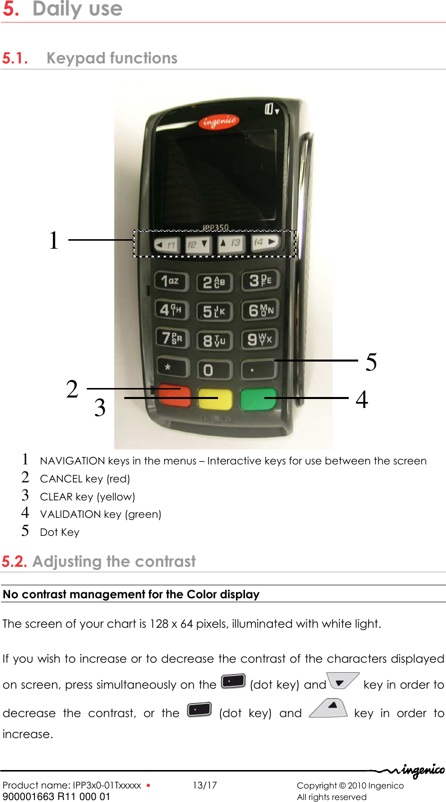
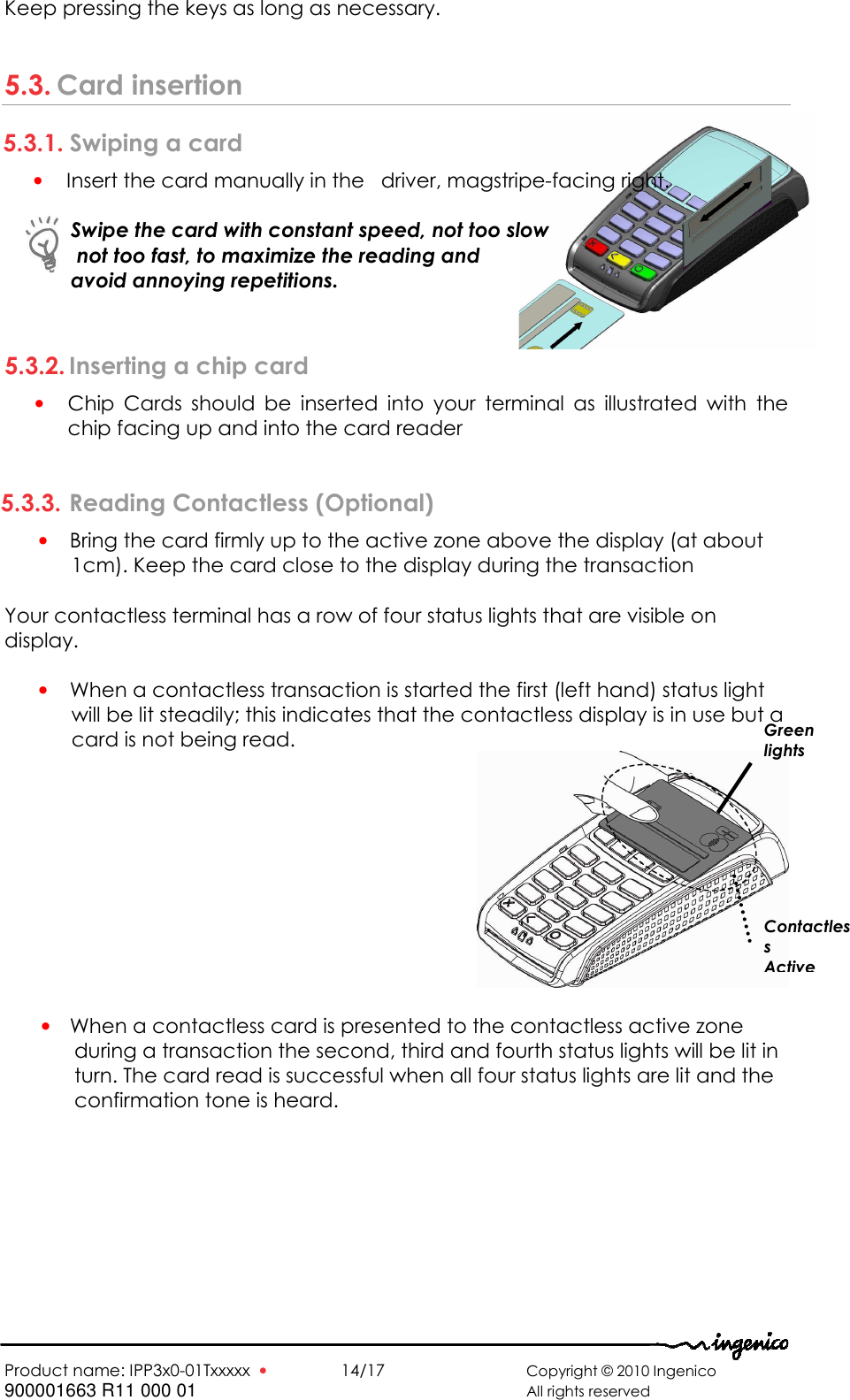
Ingenico IPP3X0-01TXXX RFID TAG READER User Manual 900001663 R11 000 02 IPP3xx User guide

INGENICO RFID TAG READER 900001663 R11 000 02 IPP3xx User guide

Manual_2010-6-9_User Manual - XKB-iPP3x0-01Txxx

  Ingenico – 190-192 Avenue Charles de Gaulle 92200 Neuilly sur Seine Tél. 33(0)1 46 25 82 00 - Fax 33 (0)1 47 72 56 95 Product name: IPP3x0-01Txxxxx U s e r  G u i d e
  Product name: IPP3x0-01Txxxxx  •    2/17       Copyright © 2010 Ingenico 900001663 R11 000 01       All rights reserved  Contents 1. Introduction _________________________________________________ 3 2. Unpacking __________________________________________________ 4 3. Recommendations __________________________________________ 4 3.1. Security_____________________________________________________________4 3.2. Security of your terminal _____________________________________________4 3.3. EC standard compliance marking ___________________________________5 3.4. Main Characteristics ________________________________________________6 4. Installation and connection __________________________________ 7 4.1. Positioning the terminal ______________________________________________7 4.2. Connections ________________________________________________________7 4.2.1. Cable or adaptor connection ________________________________________________ 7 4.2.2. Cable or adaptor disconnection______________________________________________ 8 4.2.3. Installation of the Magic Box (optional) ________________________________________ 9 4.3. Installing SAM (Secure access module) and MicroSD Card___________ 10 4.4. Installing contact less module______________________________________ 11 5. Daily use ___________________________________________________ 13 5.1. Keypad functions _________________________________________________ 13 5.2. Adjusting the contrast _____________________________________________ 13 5.3. Card insertion_____________________________________________________ 14 5.3.1. Swiping a card______________________________________________________________ 14 5.3.2. Inserting a chip card ________________________________________________________ 14 5.3.3. Reading Contactless (Optional)______________________________________________ 14 6. Maintenance_______________________________________________ 15 Cleaning of the terminal ______________________________________________ 15 6.1. Transport and storage _____________________________________________ 15 6.2. Troubleshooting ___________________________________________________ 15 6.3. End of life_________________________________________________________ 16
  Product name: IPP3x0-01Txxxxx  •    3/17       Copyright © 2010 Ingenico 900001663 R11 000 01       All rights reserved   1. Introduction Thank you for choosing a payment terminal Ingenico. We  recommend  you  to  read  carefully  this  installation  guide:  It  gives  you  the necessary  information  about  safety  precautions,  unpacking,  installation,  and maintenance of your terminal.  WARRANTY / SECURITY To benefit from the guarantee-related product, and to respect the security, we ask  you  to  use  only  accessories  delivered  in  box  with  the  product,  entrusting maintenance operations only to an authorized person.  The  IPP3X0-01TXXXXX  can  be  powered  by  different  sources  please  respect these recommendations: IPP3X0-01TXXXXX  can  be  USB  powered;  it  must  be  connected  to  a  full compatible USB link. IPP3X0-01TXXXXX  can  be  Power  Over  Ethernet  (POE)  powered;  it  must  be connected to a full compatible POE link. When  IPP3X0-01TXXXXX  is  driven  by  RS232,  it  must  be  power  by  the  specific alimentation furnished by Ingenico.  Failure  to  comply  with  these  instructions  will  void  the  manufacturer’s responsibility.        This symbol indicates an important Warning.    This symbol indicates a piece of advice.
  Product name: IPP3x0-01Txxxxx  •    4/17       Copyright © 2010 Ingenico 900001663 R11 000 01       All rights reserved  2. Unpacking ADVICE Carefully  preserve  the  packaging  of  the  IPP3X0-01TXXXXX.  It  must  be  re-used whenever the terminal is shipped.  According  to  the  model,  the  following  items  are  included  in  the  IPP3X0-01TXXXXX box (including optional accessories): • The IPP3X0-01TXXXXX terminal  • This installation guide • The IPP3X0 cradle (optional) • The connection cable or adaptor (optional) • The application user guide (optional)  3. Recommendations 3.1. Security Power on/Power down  To  power  on  or  power  down  the IPP3X0-01TXXXXX  connect  or  disconnect the cable connected to the host (for USB or Power Over Ethernet)  If the serial link is used with additional power supply: The disconnecting device of the equipment is the separable plug of the power supply cord. Therefore the socket outlet shall be installed near  the equipment and shall be easily accessible by the operator.   Lithium battery The IPP3X0-01TXXXXX is fitted with a lithium battery which is not accessible to the user.  Only  a  qualified  technician  may  be  authorized  to  open  the  unit  and change this component. SAM, MMC and contacless lid The lid located under the terminal (see  chapter “Installation SAM”) must be in place during normal operation of the terminal. 3.2. Security of your terminal Upon  receipt  of  your  terminal  you  should  check  for  signs  of  tampering  of  the equipment.  It  is  strongly  advised  that  these  checks  are  performed  regularly after receipt. You should check, for example: that the keypad is firmly in place; that there is  no  evidence  of  unusual  wires that have been connected  to  any ports on your  terminal or  associated equipment,  the chip card reader, or  any other  part  of  your  terminal.  Such  checks  would  provide  warning  of  any unauthorised modifications to your terminal, and other suspicious behaviour of individuals  that  have  access  to  your  terminal.  Your  terminal  detects  any “tampered state”. In this state the terminal will repeatedly flash  the message” Alert  Irruption!”  and  further  use  of  the  terminal  will  not  be  possible.  If  you observe  the  “Alert  Irruption!”  message,  you  should  contact  the  terminal helpdesk immediately. You are strongly advised to ensure that privileged access to your terminal is only granted to staff that have been independently verified as being trustworthy.
  Product name: IPP3x0-01Txxxxx  •    5/17       Copyright © 2010 Ingenico 900001663 R11 000 01       All rights reserved   CAUTION NEVER  ask  the  customer  to  divulge  their  PIN  Code.  Customers  should  be advised to ensure that they  are  not  being overlooked when  entering their PIN Code. 3.3. EC standard compliance marking EC standard compliance marking certifies that the product stipulated below: IPP3X0-01TXXXXX • conforms to the following harmonized standards : – IEC/EN 60950-1: Electrical safety of data processing equipment including electrical office equipment. Issue dec. 2001 EN  55022:  Data  processing  equipment  –  Radiofrequency  disturbance characteristics  -  Limits  and  measurement  methods.  EN  55022  2006  +  A1 (2007) – EN 55024: Data processing equipment – Immunity characteristics - Limits and measurement methods. Issue 1998 + A1- 2001 + A2 - 2003 3.4. FCC Statement  FCC standard compliance marking certifies that the product stipulated below: IPP3X0-01TXXXXX • conforms to the following harmonized standards : – part 15 subpart B of the FCC rules  This class (B) digital apparatus complies with Canadian ICES-003.  Information to users: Changes or modifications not expressly approved by the party responsible for compliance could void the user’s authority to operate the equipment.  NOTE: This equipment has been tested and found to comply with the limits for a Class  B  digital  device,  pursuant  to  part  15  of  the  FCC  Rules.  These  limits  are designed  to  provide  reasonable  protection  against  harmful  interference  in  a residential  installation.  This  equipment  generates  uses  and  can  radiate  radio frequency  energy  and,  if  not  installed  and  used  in  accordance  with  the instruction, may cause harmful interference to radio communications. However, there is no guarantee that interference will not occur in a particular installation. If  this  equipment  does  cause  harmful  interference  to  radio  or  television reception which can be determined by turning the equipment off and on, the user  is  encouraged  to  try  to  correct  interference  by  one  or  more  of  the following measures: - Reorient or relocate the receiving antenna. - Increase the separation between the equipment and receiver. - Connect the equipment into an outlet on circuit different from that to which the receiver is connected. - Consult the dealer or an experienced radio/TV technician for help.
  Product name: IPP3x0-01Txxxxx  •    6/17       Copyright © 2010 Ingenico 900001663 R11 000 01       All rights reserved   3.5. Main Characteristics The  main  technical  characteristics  of  the  terminal  Ingenico  IPP3X0-01TXXXXX are:  Mass  260 g without cable Dimensions  169,5 x 83x 42 mm (l x w x h) Operating conditions  Ambient temperature  from +5°C to +40°C Max relative humidity  85% at +40°C Link  USB,  Power  Over  Ethernet  or  RS232 and power supply Storage conditions  Storage temperature  -20°C,+55°C Max relative humidity  85% at +55°C
  Product name: IPP3x0-01Txxxxx  •    7/17       Copyright © 2010 Ingenico 900001663 R11 000 01       All rights reserved   4. Installation and connection 4.1. Positioning the terminal Install the  terminal  on a  flat  surface, with an easy access to  an electrical outlet if needed. Place the terminal away from any heat source and protected from dust, vibrations  and  electromagnetic  radiations  (away  from  video  terminals,  PC,  anti-shoplifting barriers, ...). 4.2. Connections A connection area is located on the rear of the terminal. In this place it’s possible to plug one of the different specific cables, or an adaptor to replace directly an other product on the field. In this last case, the specific adaptor must be chosen in the Ingenico range. 4.2.1. Cable or adaptor connection • Present the device in front of the connector and plug it
  Product name: IPP3x0-01Txxxxx  •    8/17       Copyright © 2010 Ingenico 900001663 R11 000 01       All rights reserved                          CAUTION Use only Ingenico cable or accessory not to void warranty.   4.2.2. Cable or adaptor disconnection • On specific cable, an handle helps the disconnection                Cables and accessory are able to be fixed with two  M2.5x8  screws  (not  included  in  the package)
  Product name: IPP3x0-01Txxxxx  •    9/17       Copyright © 2010 Ingenico 900001663 R11 000 01       All rights reserved  4.2.3. Installation of the Magic Box (optional)  ADVICE It is strongly recommended to attach the “Magic cable” to terminal’s work area in order to reduce stress on the terminal and connection.                  Examples of securing the “Magic Cable” are as illustrated: 1 Using the supplied cable tie to attach to a table leg (or similar) 2 Using the supplied cable tie and self-adhesive support 3 Using a counter-sunk screw (not supplied) to an appropriate surface   • The “Magic Cable” should be readily accessible for support and terminal helpdesk diagnosis purposes.  Note:  The  connection  Magic  Box  can  also  be  attached  using  a  VELCRO™  or other system.  1  3 2
  Product name: IPP3x0-01Txxxxx  •    10/17      Copyright © 2010 Ingenico 900001663 R11 000 01       All rights reserved         4.3. Installing  SAM (Secure  access  module)  and  MicroSD Card CAUTION :  Before starting, switch off the terminal by disconnecting the power supply or the link to the host  In order to access the SAM card you must first remove the SAM compartment cover located at the back of your terminal.  • Press the two clips of the cover and open the cover.          • Insert completely the MicroSD Card into the slot marked (MicroSD) as indicated on the figure.  Take care to ensure that the MicroSD Card is inserted in the correct manner.    • Insert  the  SAM  Card  into  the  slot  marked  (1),(2)  or  (3).  Take  care  to ensure  that  the  SAM  Card  is  inserted  in  the  correct  manner.  The  cut corner must be positioned as indicated on the figure.   • To  remove  SAM  card,  we  suggest  you  to  use  a  piece  of  adhesive previously pasted on both sides of the SAM as shown here below       CAUTION:  Do not use any tools when installing or removing the SAM Card.       SAM Cut corner Adhesive
  Product name: IPP3x0-01Txxxxx  •    11/17      Copyright © 2010 Ingenico 900001663 R11 000 01       All rights reserved         Replace the cover as illustrated by the procedure below:                       SAM  door  is  able  to  be  fixed  with  one  M2.5x8  screw  (not  included  in  the package)   4.4. Installing contact less module CAUTION:  Before starting, switch off the terminal by disconnecting the power supply.  • Open the cover as indicated at chapter 4.3
  Product name: IPP3x0-01Txxxxx  •    12/17      Copyright © 2010 Ingenico 900001663 R11 000 01       All rights reserved  Do not force at the insertion.
  Product name: IPP3x0-01Txxxxx  •    13/17      Copyright © 2010 Ingenico 900001663 R11 000 01       All rights reserved  5. Daily use 5.1.   Keypad functions  1 NAVIGATION keys in the menus – Interactive keys for use between the screen   2 CANCEL key (red) 3 CLEAR key (yellow)  4 VALIDATION key (green) 5 Dot Key 5.2. Adjusting the contrast No contrast management for the Color display  The screen of your chart is 128 x 64 pixels, illuminated with white light.  If you wish to increase or to decrease the contrast of the characters displayed on screen, press simultaneously on the   (dot key) and  key in order to decrease  the  contrast,  or  the    (dot  key)  and    key  in  order  to increase. 1 4 2  3 5
  Product name: IPP3x0-01Txxxxx  •    14/17      Copyright © 2010 Ingenico 900001663 R11 000 01       All rights reserved   Keep pressing the keys as long as necessary.  5.3. Card insertion 5.3.1. Swiping a card • Insert the card manually in the   driver, magstripe-facing right.   Swipe the card with constant speed, not too slow  not too fast, to maximize the reading and  avoid annoying repetitions.  5.3.2. Inserting a chip card • Chip  Cards  should  be  inserted  into  your  terminal  as  illustrated  with  the chip facing up and into the card reader  5.3.3. Reading Contactless (Optional) • Bring the card firmly up to the active zone above the display (at about 1cm). Keep the card close to the display during the transaction  Your contactless terminal has a row of four status lights that are visible on display.  • When a contactless transaction is started the first (left hand) status light will be lit steadily; this indicates that the contactless display is in use but a card is not being read.   • When a contactless card is presented to the contactless active zone during a transaction the second, third and fourth status lights will be lit in turn. The card read is successful when all four status lights are lit and the confirmation tone is heard.  Green lights Contactless  Active
  Product name: IPP3x0-01Txxxxx  •    15/17      Copyright © 2010 Ingenico 900001663 R11 000 01       All rights reserved   6. Maintenance ATTENTION Before making any operations of maintenance in the terminal, make sure that  power supply is disconnected. Cleaning of the terminal First of all, unplug all the wires from the terminal.  Good rules for proper cleaning of the terminal are:  • Use a soft cloth that is very slightly soaked with soapy water to clean the outside of the terminal. • Do not clean the electrical connections. • Do not use in any case, solvents, detergents or abrasive products:  Those materials might damage the plastic or electrical contacts. • Avoid exposing the terminal to the direct rays of the sun. • Do not put anything into the slot of the smart card reader  6.1. Transport and storage • Use the original packaging for any unit or stored. • Disconnect all cables from the terminal during the transport. 6.2. Troubleshooting The terminal does not turn on or does not connect to the telephone line  • Check the power supply and telephone line cables  • Check for electrical power network   The terminal fails to establish a telephone connection • Check that the tone of the phone line is free • Check the configuration of the phone line and number to call  • Get support from technical   Cards are not read • Check that the magnetic card is passed correctly (with magnetic band  directed to the interior of the terminal)  • Swipe again the card with the magnetic stripe movement constant and rapid  • Verify that the magnetic strip is not damaged, grooved or cracked • Make sure you have inserted correctly the smart card into the smart card reader and removed the card only after the transaction  The ticket is not printed • Check the presence and proper positioning of the paper roll.  Possibly adjust the paper roll following instructions present in this manual  • Check the type of paper used (thermal paper must be used)
  Product name: IPP3x0-01Txxxxx  •    16/17      Copyright © 2010 Ingenico 900001663 R11 000 01       All rights reserved  6.3. End of life The product belongs to the family of electrical and electronic equipment. Therefore, it is subjected to the WEEE directive which requires the collection and the recycling at the end of life product.  The Ingenico products present the symbol for the marking of electrical and electronic equipment as required by the WEEE Directive.   The crossed-out wheeled bin printed on the product gives the information about the requirement not to dispose of WEEE as unsorted municipal waste and to collect such WEEE separately.  To assure that the product is collected and recycled with respect to the environment, you must contact your supplier (in defect, contact the Ingenico local office or the commercial head office in charge of your country on www.ingenico.com, « contact us » page).  The  abandonment  or  uncontrolled  disposal  of  waste  can  cause  harm  to environment  and  to  human  health.  So,  by  recycling  your  product  in  a responsible manner, you contribute to the preservation of natural resources and to the protection of human health.
  Product name: IPP3x0-01Txxxxx  •    17/17      Copyright © 2010 Ingenico 900001663 R11 000 01       All rights reserved     Ingenico 192 avenue Charles de Gaulle  92200 Neuilly sur Seine - France Tél.:  +  33  1  46  25  82  00  -  Fax:  +  33  1  47  72  56  95 www.ingenico.com  Ingenico 192 avenue Charles de Gaulle  92200 Neuilly sur Seine - France Tél.: + 33 1 46 25 82 00 - Fax: + 33 1 47 72 56 95 www.ingenico.com Your contact 296108011AB “This  Document  is  Copyright  ©  2010  by  INGENICO  Group.  INGENICO  retains  full copyright  ownership,  rights  and  protection  in  all  material  contained  in  this  document. The  recipient  can  receive  this  document  on  the  condition  that  he  will  keep  the document  confidential  and  will  not  use  its  contents  in  any  form  or  by  any  means, except  as  agreed  beforehand,  without  the  prior  written  permission  of  INGENICO. Moreover,  nobody  is  authorized  to  place  this  document  at  the  disposal  of  any  third party  without  the  prior  written  permission  of  INGENICO.  If  such  permission  is  granted, it will be subject to the condition that the recipient ensures that any other recipient of this document,  or  information  contained  therein,  is  held  responsible  to INGENICO  for  the confidentiality of that information.   Care  has  been  taken  to  ensure  that  the  content  of  this  document  is  as  accurate  as possible. INGENICO  however  declines  any  responsibility  for  inaccurate,  incomplete  or outdated  information.  The  contents  of  this  document  may  change  from  time  to  time without  prior  notice,  and  do  not  create,  specify,  modify  or  replace  any  new  or  prior contractual obligations agreed upon in writing between INGENICO and the user.   INGENICO is not responsible for any use of this device, which would be non consistent with the present document.

Navigation menu