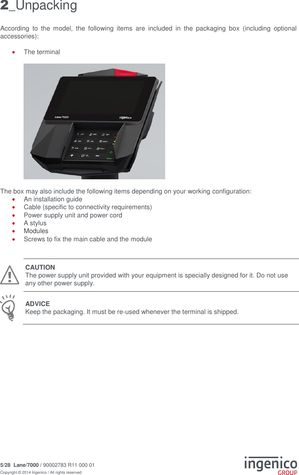
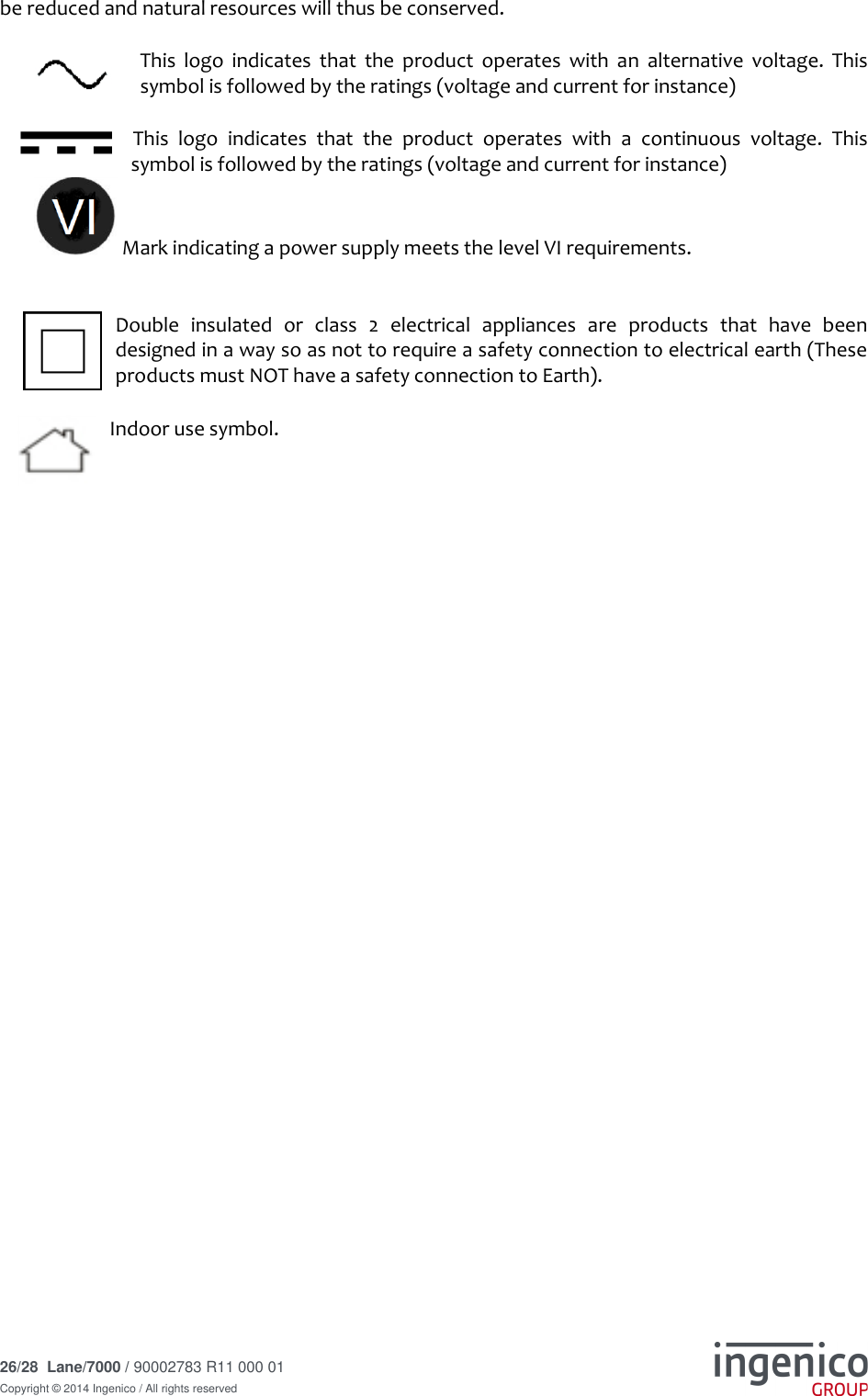
Ingenico L7000CL Lane/7000 Signature capture payment terminal User Manual User Guide

INGENICO Lane/7000 Signature capture payment terminal User Guide

user manual

 www.ingenico.com 28/32, boulevard de Grenelle, 75015 Paris - France / (T) +33 (0)1 58 01 80 00 / (F) +33 (0)1 58 01 91 35 Ingenico – S.A. au capital de 53 086 309 €  /  317 218 758 RCS PARIS    Lane/7000 User Guide  90002783 R11 000 01
 2/28  Lane/7000 / 90002783 R11 000 01 Copyright © 2014 Ingenico / All rights reserved   Contents     1_ Introduction ...................................................................................... 4 2_ Unpacking ........................................................................................ 5 3_ Recommendations ........................................................................... 6 3_1 Safety ............................................................................................................. 6 3_2 Security of your terminal (tampering attempt detection) ................................. 7 3_3 Main Characteristics ...................................................................................... 9 3_3_1 Terminal.......................................................................................................................... 9 3_3_2 Power characteristics ................................................................................................... 10 3_3_3 Lane/7000 Power values in different modes ................................................................ 11 3_4 Functional description .................................................................................. 12 3_5 Installation & Connections............................................................................ 13 3_5_1 Positioning the terminal ................................................................................................ 13 3_5_2 Inserting SAM (Secure access module) and Micro SD ................................................ 13 3_5_3 Connecting the terminal to the host ............................................................................. 15 3_5_4 Setting the Lane/7000 on the standpole adaptor ......................................................... 16 4_ Daily use ......................................................................................... 18 4_1 Card reading ................................................................................................ 18 4_1_1 Swiping a card .............................................................................................................. 18 4_1_2 Inserting a smart card ................................................................................................... 18 4_1_3 Reading a contactless card .......................................................................................... 18 4_2 Signature capture ......................................................................................... 19 4_3 Audio ............................................................................................................ 19 5_ Maintenance ................................................................................... 20 5_1 Cleaning ....................................................................................................... 20 5_1_1 Cleaning of the terminal ............................................................................................... 20 5_1_2 Entretien du terminal .................................................................................................... 20 5_1_3 Wartung von Endgeräten ............................................................................................. 20 5_2 Transport and storage .................................................................................. 21 5_3 Troubleshooting ........................................................................................... 21
 3/28  Lane/7000 / 90002783 R11 000 01 Copyright © 2014 Ingenico / All rights reserved   6_ Cables ............................................................................................. 22 7_ Norms & Marking ........................................................................... 24 7_1 Federal Communications Commission (FCC) Statement ............................ 24 7_2 Industry Canada (IC) Statement. ................................................................. 24 7_3 Environment (WEEE, Batteries and Packaging) .......................................... 25 7_4 Marking ........................................................................................................ 25
 4/28  Lane/7000 / 90002783 R11 000 01 Copyright © 2014 Ingenico / All rights reserved   1_Introduction Thank you for choosing an Ingenico payment terminal.  We recommend  you to  read carefully  this user guide:  it gives  you the  necessary information  about safety precautions, unpacking, installation and maintenance of your terminal.     WARRANTY / SECURITY To benefit from the guarantee-related product, and to respect the security, we ask you to use only the power supply delivered in box with the product, entrusting maintenance operations only to an authorized person. Failure to comply with these instructions will void the manufacturer’s responsibility.              This symbol indicates an important Warning.  This symbol indicates a piece of advice.
 5/28  Lane/7000 / 90002783 R11 000 01 Copyright © 2014 Ingenico / All rights reserved   2_Unpacking According  to  the  model,  the  following  items  are  included  in  the  packaging  box  (including  optional accessories):   The terminal         The box may also include the following items depending on your working configuration:  An installation guide  Cable (specific to connectivity requirements)  Power supply unit and power cord  A stylus  Modules  Screws to fix the main cable and the module    CAUTION The power supply unit provided with your equipment is specially designed for it. Do not use any other power supply.  ADVICE  Keep the packaging. It must be re-used whenever the terminal is shipped.
 6/28  Lane/7000 / 90002783 R11 000 01 Copyright © 2014 Ingenico / All rights reserved   3_Recommendations 3_1 Safety  Power on/Power down – Emergency stop To power on or power down the terminal, connect or disconnect the power supply from the electric outlet.  Power supply unit   CAUTION Only use the power supply AC/DC provided with Lane/7000 or the power provided by a cash register limited power source (LPS).  Authorized power supply units:   Desktop Power Supply units have to be connected to the mains with one of these cables: - Power cord 189609046 (EU) - Power cord 188413214 (US)    CAUTION Lithium battery cell     The terminal is  fitted  with  a lithium battery cell  which  is not  accessible to  the user. Only a qualified technician is authorized to open the unit and change this component. Risk of explosion if the battery is replaced by an incorrect type. Dispose of used battery according to the instructions.  Electrical power supply network The electrical outlet must meet the following criteria:    Must be installed near the equipment and easily accessible;  Must meet standards and regulations in the country of use. Explosion areas Certain regulations restrict the use of  radio  equipment  in chemical  plants,  fuel depots and any site where blasting is carried out. You are urged to comply with these regulations. The terminal shall be protected by a specially fitted and certified cover enabling use in proximity to a fuel pump. Connection of headset     on audio jack   Power Supply Unit Supplier Type Supplier reference Electrical characteristics Ingenico  part number PHIHONG TECHNOLOGY Co. Ltd Desktop PSM24W-080L6IN-R 8VDC  3A Level VI 296198809 PHIHONG TECHNOLOGY Co. Ltd Wallplug PSC16E-080L6IN-R PSC16A-080L6IN-R 8VDC  2A Level VI 296199611 296196003
 7/28  Lane/7000 / 90002783 R11 000 01 Copyright © 2014 Ingenico / All rights reserved    CAUTION An excessive acoustic pressure of headset can involve deafness!  3_2 Security of your terminal (tampering attempt detection) Your device fulfils current applicable PCI PTS security requirements. Upon receipt of your terminal you should check for signs of tampering of the equipment. It is strongly advised that these checks are performed regularly after receipt. You should check, for example: that the keypad is firmly in place; that there is no evidence of unusual wires that have been connected to any ports on  your terminal or associated equipment, the chip card reader or any other part  of your terminal. Such checks would provide warning of any unauthorised modifications to your terminal, and other suspicious behaviour of individuals that have access to your terminal.  Your  terminal  detects  any  “tampered  state”.  In  this  state  the  terminal  will  repeatedly  flash  the message” Alert Irruption!” and further use of the terminal will not be possible. If you observe the “Alert Irruption!” message, you should contact the terminal helpdesk immediately. You are strongly advised to ensure that privileged access to your terminal is only granted to staff that have been independently verified as being trustworthy.  The terminal must never be put in or left at a location where it could be stolen or replaced by another device.       WARNING If the warranty label is torn or removed, the warranty will be void.  CAUTION Positioning of the Lane/7000 on check stand must be in such a way to make cardholder PIN (Personal Identification Number) spying infeasible. Installing device on an adjustable stand must be in such a way that consumers can swivel the  terminal  sideways  and/or  tilt  it  forwards/backwards  to  a  position  that  makes  visual observation of the PIN-entry process difficult. Positioning  of  in-store  security  cameras  such  that  the  PIN-entry  keypad  is  not  visible. NEVER  ask  the  customer  to  divulge  their  PIN  Code.  Customers  should  be  advised  to ensure that they are not being overlooked when entering their PIN Code. Warranty label  (on the bottom side of the terminal)
 8/28  Lane/7000 / 90002783 R11 000 01 Copyright © 2014 Ingenico / All rights reserved     CAUTION This equipment may not be modified, altered or changed in any way without signed written permission from Ingenico
 9/28  Lane/7000 / 90002783 R11 000 01 Copyright © 2014 Ingenico / All rights reserved   3_3 Main Characteristics  3_3_1 Terminal Weight  (Poids, Gewicht) 583g (20.56 oz) Size (dimensions, Maße) 181 (L) x 152 (W) x 35.2 (H) mm Display 5” backlit LCD, WVGA (800 x 480 pixels) Touchscreen Capacitive   Operating conditions Ambient temperature from 0°C to +45°C Max relative humidity 85% RH non-condensing at +40°C Max altitude 2000 m  Storage conditions Storage temperature -20°C, +55°C Max relative humidity 85% at +55°C
 10/28  Lane/7000 / 90002783 R11 000 01 Copyright © 2014 Ingenico / All rights reserved    3_3_2 Power characteristics   Power supply units  The Lane/7000 can be powered by several ways:  An external power supply unit  By POE (Power over Ethernet)  By USB (5VDC or 12VDC)  The characteristics for each type of power supply are detailed hereafter.  Power supply unit   296198809 296199611 296196003 Model Name PSM24W-080L6IN-R PSC16E-080L6IN-R PSC16A-080L6IN-R Weight 243 g  (8.57 oz) 160g  (5.6 oz) 160g  (5.6 oz) Size (l x w x h) 120 x 50 x 31 mm 74 x 35 x 46.2 mm 74 x 35 x 46.2 mm Class Level VI Level VI Level VI  Input voltage AC 100-240V 50-60Hz AC 100-240V 50-60Hz AC 100-240V 50-60Hz Output voltage DC 8V 3A DC 8V 2A DC 8V 2A    WARNING The power supply unit provided with your equipment is specially designed for this Ingenico terminal. Do not use any other power supply. The use of a power supply with apparently similar voltage/current characteristics may damage your terminal.  AVERTISSEMENT Dans le cas où vous choisiriez d’utiliser un bloc alimentation, assurez-vous de n’utiliser que le bloc d'alimentation qui a été conçu spécialement pour votre terminal. N'utilisez pas d'autre bloc d'alimentation. L'emploi d'un bloc d'alimentation présentant des caractéristiques apparemment similaires de tension/intensité peut endommager votre terminal.  WARNHINWEIS Nur das Netzteil, das speziell für Ihr Gerät ausgelegt wurde, benutzen. Benutzen Sie kein anderes Netzteil. Die Benutzung eines Netzgeräts mit scheinbar ähnlicher Spannung/Stromstärke kann zur Beschädigung Ihres Terminals führen.
 11/28  Lane/7000 / 90002783 R11 000 01 Copyright © 2014 Ingenico / All rights reserved   3_3_3 Lane/7000 Power values in different modes  Lane/7000 works at voltages between 8VDC and 12VDC.  Mode Lane/7000 Power (W) Idle mode - backlight OFF 3 Idle mode - backlight ON 3.7 Typical – smartcard and contactless in test - Backlight ON 5 Maximum (+2 Loads of 2.5W each) 12     POE (Power over Ethernet) The power sourcing equipment must be compliant with IEEE802.3af standard, class 0 which means 12.95W max.
 12/28  Lane/7000 / 90002783 R11 000 01 Copyright © 2014 Ingenico / All rights reserved     3_4 Functional description
 13/28  Lane/7000 / 90002783 R11 000 01 Copyright © 2014 Ingenico / All rights reserved   3_5 Installation & Connections 3_5_1 Positioning the terminal Place the terminal with an easy access to an electrical outlet. Place the terminal away from any heat source and protected from dust, vibrations and electromagnetic radiations (away from video terminals, PC, anti-shoplifting barriers  ...). The terminal is exclusively made for indoor use. The Lane/7000 device may be mounted on a flat surface, wall, or customer stand.    CAUTION Do not place the Lane/7000 device on a PC monitor, adjacent to an electronically active security tag deactivation system, or near other sources of magnetic fields.   The Lane/7000 device must be at least 30 centimeters (12 inches) away from an electronically active type of security tag deactivation pad. There are two types of security tag deactivation systems:  An electronically active system sends out a powerful and potentially disruptive signal to deactivate the security tag. If the Lane/7000 device is placed too close to the system’s pad, or placed above the pad, the product may not work properly.  A passive system is a permanent magnet type that does not send out a signal. This type should not affect the Lane/7000 device.   3_5_2 Inserting SAM (Secure access module) and Micro SD  CAUTION Before starting, switch off the terminal by disconnecting the power supply.  Perform the following operations:  Unscrew the modules and remove them both  Access to SAM and Micro SD is now possible.
 14/28  Lane/7000 / 90002783 R11 000 01 Copyright © 2014 Ingenico / All rights reserved       Insert the SAM Card into the slot marked (1), (2) or (3). Take care to ensure that the SAM Card is inserted in the correct manner. The cut corner must be positioned as indicated on the figure below.          Slide back the module and screw them tight
 15/28  Lane/7000 / 90002783 R11 000 01 Copyright © 2014 Ingenico / All rights reserved       CAUTION Do not use any tools when installing or removing the SAM Card or Micro SD.    WARNING During this operation, it is necessary to be in an ESD protected environment. As this is not very easy, it is recommended to make this operation using ESD shoes for example  3_5_3 Connecting the terminal to the host  CAUTION Connecting must be made when power supply unit is not plugged in the cable.
 16/28  Lane/7000 / 90002783 R11 000 01 Copyright © 2014 Ingenico / All rights reserved     Flip the terminal. There is one port on the back for power and communications.   Connect the cable on the terminal.   Connect the other end to the power supply unit and a Host (PC / cash register…).  Plug the power supply into the mains.   WARNING The main port at the back must not be used to connect an HDMI video cable.  Only connect cables provided by Ingenico.   Note: 2 screws can be added (M2.5 x 8) to hold more firmly the cable.  3_5_4 Setting the Lane/7000 on the stand pole adaptor  Install the terminal on a flat surface is not possible on the Lane/7000 as is. It is designed to be fitted on a stand pole adaptor. A specific pattern by Ingenico has been developed to fit the lane/7000.    To fit the Lane/7000 to the stand pole adaptor, it only requires sliding down the Lane/7000 until a click sound:
 17/28  Lane/7000 / 90002783 R11 000 01 Copyright © 2014 Ingenico / All rights reserved              The Lane/7000 is now ready to use:
 18/28  Lane/7000 / 90002783 R11 000 01 Copyright © 2014 Ingenico / All rights reserved    4_Daily use 4_1 Card reading 4_1_1 Swiping a card  Insert  the  card  manually  in  the  reader,  magnetic  stripe  facing  the  main body  of  the  terminal,  and  slide  the  card  from  the  rear  to  the  front  in  a continuous motion for best results.    Swipe the card with constant speed, neither too slowly nor too fast, to maximize the reading efficiency and avoid annoying repetitions.   4_1_2 Inserting a smart card  Chip cards should be inserted into your terminal as illustrated with the chip facing up and into the card reader.    4_1_3 Reading a contactless card  Bring  the  card  to  the  active  zone  above  the  contactless  logo  (at  about 1cm).  Keep the card close to the contactless logo during the transaction.   Your contactless terminal provides four contactless status lights located above the contactless logo.   When a contactless transaction is started the first (left hand) status light will be lit steadily; this indicates that the contactless is in use but a card is not being read.   When a contactless card is presented to the contactless active zone during a transaction the second, third and fourth status lights will be lit in turn. The card read is successful when all four status lights are lit and a confirmation tone can be heard.        CAUTION Do not stick any label onto the contactless active zone. It can decrease seriously contactless efficiency.  CAUTION Avoid metallic parts around the contactless area.
 19/28  Lane/7000 / 90002783 R11 000 01 Copyright © 2014 Ingenico / All rights reserved   4_2 Signature capture   The signature capture is done with a stylus and a capacitive touchscreen    4_3 Audio A speaker is available there is also an Audio jack. When a headset is plugged in, there is no more sound from the speaker  The audio jack   is located next to the card reader.   This option is not designed to play music, but to facilitate the use by blind people.   The jack is 3.5mm, 32 ohms impedance.
 20/28  Lane/7000 / 90002783 R11 000 01 Copyright © 2014 Ingenico / All rights reserved   5_Maintenance  5_1 Cleaning  5_1_1 Cleaning of the terminal  CAUTION Before making any operations of maintenance in the terminal, make sure that the power supply is disconnected.   First of all, unplug all the wires from the terminal. Good rules for proper cleaning of the terminal are:   Use Ingenico Cleaning kit: http://www.ingenico.cleaningcards.com/  Do not clean the electrical connections.  Do not use in any case, solvents, detergents or abrasive products: o  Those materials might damage the plastic or electrical contacts.  Avoid exposing the terminal to the direct rays of the sun.  Do not put anything into the slot of the smart card reader  5_1_2 Entretien du terminal   ATTENTION Assurez-vous que tous les câbles sont bien débranchés du terminal avant toute intervention de maintenance sur le terminal  Avant tout, débranchez tous les câbles du terminal. Pour bien nettoyer le terminal :   Utilisez les kits de nettoyage Ingenico : http://www.ingenico.cleaningcards.com/  Ne nettoyez pas les connexions électriques.  N'utilisez jamais de solvants, de détergents, d’alcool ou de produits abrasifs :  o  Ces produits peuvent endommager le plastique ou les contacts électriques.  Evitez d'exposer le terminal aux rayons directs du soleil.  N'insérez rien dans la fente du lecteur de carte.  5_1_3 Wartung von Endgeräten    ACHTUNG Stellen Sie vor jeglicher Wartungsarbeit an dem Terminal sicher, dass die Stromversorgung unterbrochen ist  Als erstes alle Kabel vom Terminal trennen. Regeln für eine ordnungsgemässe Reinigung des Terminals:    Für  die  Außenseite  des  Terminals,  Ingenico  Cleaning  kits  benutzen: http://www.ingenico.cleaningcards.com/
 21/28  Lane/7000 / 90002783 R11 000 01 Copyright © 2014 Ingenico / All rights reserved    Keine elektrischen Anschlüsse reinigen.  Auf keinen Fall Lösungsmittel, Waschmittel oder Scheuermittel verwenden: o  diese Mittel können den Kunststoff oder elektrische Kontakte beschädigen.  Das Terminal keiner direkten Sonneneinstrahlung aussetzen.  Nichts in den Schlitz des Chipkartenlesers einführen.   CAUTION Before making any operations of maintenance in the terminal, make sure that the power supply is disconnected.  5_2 Transport and storage  Use the original packaging for storage or returning the unit.  Disconnect all cables from the terminal during the transport.  5_3 Troubleshooting Device is not working  Make sure that the Lane/7000 connector is fully inserted into the back of the device.  Restart the device.  If you have another working Lane/7000 device, swap the devices to determine if the problem is with the device, cable, POS, or power supply.  If the Lane/7000 device is directly connected to a host, reset the host by turning it off and back on again.  Magnetic Card Reader Does Not Work Properly  When sliding the card through the reader, make sure that the magnetic stripe on the card is facing the Lane/7000 display screen (see Swiping a Magnetic Stripe Card).  Swipe the card at a faster or middle steady speed.  Inspect the magnetic stripe on the card to make sure it is not scratched or badly worn.  Security tag deactivation system could disturb the magnetic card reader   To determine if the problem is with the card: a. If your host device has a magnetic stripe reader, try swiping the card there. b. If you have another working Lane/7000 device, try swiping the card there.  Smart Card Reader Does Not Work Properly  Make sure you have inserted correctly the smart card into the smart card reader and removed the card only after the transaction  MicroSD Card Reader Does Not Work Properly  Make sure you have inserted correctly the microSD card into the card reader.  Check that the card capacity is not higher than 32GB.  Touchscreen / Signature Capture Does Not Work Properly  Make sure you use the correct power supply.   Replace the stylus   WARNING Changes or modifications to this device not expressly approved by the party responsible for compliance could void the user's authority to operate the equipment.
 22/28  Lane/7000 / 90002783 R11 000 01 Copyright © 2014 Ingenico / All rights reserved   6_Cables The terminal can be connected to the host by several ways, with optional cables:  High speed USB device  Ethernet  RS232 Most of the cables used with iSC and iPP ranges are compatible with the Lane/7000.  We advise to check with your reseller their compatibility if you plan to replace an iSC480 / ISC250 / ISC Touch 250 by a Lane/7000.   Following are some examples of accessories that can be used to connect the Lane/7000. This list is not exhaustive. Please contact your reseller for more information.    RS232 cable (optional)         USB cable (optional)    References:   296111170AC (length 2m)        USB powered 12V cable (optional)            USB connector Connector for terminal Power supply unit RS232 connector Connector for terminal Power supply unit Connector for terminal
 23/28  Lane/7000 / 90002783 R11 000 01 Copyright © 2014 Ingenico / All rights reserved     Ethernet cable (optional)           Ethernet connector Connector for terminal Power supply unit
 24/28  Lane/7000 / 90002783 R11 000 01 Copyright © 2014 Ingenico / All rights reserved    7_Norms & Marking  7_1 Federal Communications Commission (FCC) Statement 15.21 You are cautioned that changes or modifications not expressly approved by the part responsible for compliance could void the user’s authority to operate the equipment.  15.105(b) This  equipment  has  been  tested  and  found  to  comply  with  the  limits  for  a  Class  B  digital  device, pursuant  to  part  15  of  the  FCC  rules.  These  limits  are  designed  to  provide  reasonable  protection against  harmful  interference  in  a  residential  installation.  This  equipment  generates  uses  and  can radiate radio frequency energy and, if not installed and used in accordance with the instructions, may cause harmful interference to radio communications. However, there is no guarantee that interference will not occur in a particular installation. If this equipment does cause harmful interference to radio or television  reception,  which  can  be  determined  by  turning  the  equipment  off  and  on,  the  user  is encouraged to try to correct the interference by one or more of the following measures:  Reorient or relocate the receiving antenna.  Increase the separation between the equipment and receiver.  Connect the equipment into an outlet on a circuit different from that to which the receiver is connected.  Consult the dealer or an experienced radio/TV technician for help.   15.19 (a) (3) This  device  complies  with  Part  15  of  the  FCC  Rules.  Operation  is  subject  to  the  following  two conditions: 1) This device may not cause harmful interference and 2) This device must accept any interference received, including interference that may cause undesired operation of the device.  7_2 Industry Canada (IC) Statement.  This device complies with Industry Canada licence-exempt RSS standard(s). Operation is subject to the following two conditions: 1)  this device may not cause interference, and 2)  this  device  must  accept  any  interference,  including  interference  that  may  cause  undesired operation of the device.  Le  présent  appareil  est  conforme  aux  CNR  d'Industrie  Canada  applicables  aux  appareils  radio exempts de licence. L'exploitation est autorisée aux deux conditions suivantes: 1)   l'appareil ne doit pas produire de brouillage, et 2)   l'utilisateur  de  l'appareil  doit  accepter  tout  brouillage  radioélectrique  subi,  même  si  le brouillage est susceptible d'en compromettre le fonctionnement.
 25/28  Lane/7000 / 90002783 R11 000 01 Copyright © 2014 Ingenico / All rights reserved   7_3 Environment (WEEE, Batteries and Packaging) This  product  is  labeled  in  accordance  with  European  Directives  2002/96/EC  concerning  Waste Electrical and Electronic Equipment (WEEE) and 2006/66/EC concerning Batteries and Accumulators. Those provisions are requiring producers and manufacturers to become liable for take-back, treatment and recycling upon end of life of equipment and batteries.  The associated symbol means that WEEE and waste batteries must not be thrown away but collected separately and recycled.  Ingenico ensures that efficient collection and recycling schemes are set-up for WEEE and batteries according  to  the  local  regulation  of  your  country.  Please  contact  your  resellers  for  more  detailed information  about  the  compliance  solution  in  place  for  disposing  of  your  old  product  and  used batteries.  Packaging waste must also be collected separately to assure a proper disposal and recycling.   Please note that proper recycling of the electrical and electronic equipment and waste batteries will ensure safety of human health and environment. 7_4 Marking Below, you will find the different symbols used on the product and its power supply.  The  CE  marking  is  the  manufacturer's  declaration that  the  product  meets  the requirements  of  the  applicable  EC  directives.  The  CE  mark  is  a  mandatory conformity  marking  for  certain  products  sold  within  the  European  Economic Area (EEA).  This  TÜV  symbol  shows  consumers  at  a  glance that a  product  has  been examined by neutral experts and that there are no safety concerns  The  UL  mark  appears  on  end  products  and  complete  components  suitable  for factory and field installation. All of the products carrying these marks are covered by  our  Follow-Up  Services  program  to  determine  that  products  continue  to  be manufactured in compliance with UL’s safety requirements.  The RCM mark will be the only mark to indicate compliance with the Australian Communications  and  Media  Authority’s  (ACMA)  regulatory  arrangements  for telecommunications, radio, EMC and electromagnetic energy (EME).  The  C-Tick  is  an  identification  trademark  registered  to  the  Australian Communications  Media  Authority  (ACMA).  The  C-Tick  mark  signifies  that  the labelled  electronic  device  is  compliant  with  applicable  electromagnetic compatibility (EMC) requirements Waste of Electrical and Electronic Equipment (WEEE) symbol indicates that when the end-user wishes to discard this product, it must be sent to separate collection facilities  for  recovery  and  recycling.  By  separating  this  product  from  other household-type waste, the volume of waste sent to incinerators or land-fills will
 26/28  Lane/7000 / 90002783 R11 000 01 Copyright © 2014 Ingenico / All rights reserved   be reduced and natural resources will thus be conserved. This  logo  indicates  that  the  product  operates  with  an  alternative  voltage.  This symbol is followed by the ratings (voltage and current for instance)  This  logo  indicates  that  the  product  operates  with  a  continuous  voltage.  This symbol is followed by the ratings (voltage and current for instance)  Mark indicating a power supply meets the level VI requirements.  Double  insulated  or  class  2  electrical  appliances  are  products  that  have  been designed in a way so as not to require a safety connection to electrical earth (These products must NOT have a safety connection to Earth). Indoor use symbol.
 27/28  Lane/7000 / 90002783 R11 000 01 Copyright © 2014 Ingenico / All rights reserved    Notes
 28/28  Lane/7000 / 90002783 R11 000 01 Copyright © 2014 Ingenico / All rights reserved   “This  Document  is  Copyright  ©  2016  by  INGENICO  Group.  INGENICO  retains  full  copyright ownership, rights and protection in all material contained in this document. The recipient can receive this document on the condition that he will keep the document confidential and will not use its contents in any form or by any means, except as agreed beforehand, without the prior written  permission of INGENICO. Moreover, nobody is authorized to place this document at the disposal of any third party without the prior written permission of INGENICO. If such permission is granted, it will be subject to the  condition  that  the  recipient  ensures  that  any  other  recipient  of  this  document,  or  information contained therein, is held responsible to INGENICO for the confidentiality of that information.   Care  has  been  taken  to  ensure  that  the  content  of  this  document  is  as  accurate  as  possible. INGENICO  however  declines  any  responsibility  for  inaccurate,  incomplete  or  outdated  information. The contents of this document may change from time to time without prior notice, and do not create, specify,  modify  or  replace any new or prior contractual  obligations  agreed  upon in  writing between INGENICO and the user.   INGENICO  is  not  responsible  for  any  use  of  this  device,  which  would  be  non-consistent  with  the present document.  All trademarks used in this document remain the property of their rightful owners.”                  Ingenico 28-32 Boulevard de Grenelle  75015 Paris Tél. 33(0)1 58 01 80 00 - Fax 33 (0)1 58 01 91 35 www.ingenico.com  Your contact * 296214046 *

Navigation menu