Inkel JF46C1900CFN01 Fiber Fed Repeater User Manual
INKEL Corporation Fiber Fed Repeater
UserManual.wiki
>
Inkel
>
JF46C1900CFN01 User Manual
Users Manual
Navigation menu
Upload a User Manual
Namespaces
Wiki Guide
HTML
PDF
Info
Views
User Manual
Discussion / Help
Navigation
![JUNI JF-46-E1900/CFN03 CDMA FIBER FED REPEATER OPERATIONS MANUAL JUNI AMERICA PROPRIETARY & CONFIDENTIAL Revision 0.01 Juni America Inc. 5Table of Figures [FIGURE 1.1.1] SYSTEM CONFIGURATION...............................................................................................................9 [FIGURE 1.2.1] HANDOFF BETWEEN BTS AND REPEATER.....................................................................................11 [FIGURE 1.4.1] DONOR HUB UNIT ENCLOSURE [FIGURE 1.4.2] REMOTE UNIT .............................................13 [FIGURE 2.1.1] SYSTEM BLOCK DIAGRAM............................................................................................................19 [FIGURE 2.2.1] SIMULCAST BLOCK DIAGRAM ......................................................................................................20 [FIGURE 2.3.1] MAIN COMPONENTS OF THE DONOR HUB UNIT ...........................................................................21 [FIGURE 2.3.2] DONOR HUB UNIT SHELF INTERFACE...........................................................................................22 [FIGURE 2.3.3] DONOR HUB UNIT EXTERNAL CONNECTORS (BOTTOM VIEW).....................................................23 [FIGURE 2.4.1] MAIN COMPONENTS OF THE REMOTE UNIT ..................................................................................24 [FIGURE 2.4.2] REMOTE UNIT EXTERNAL CONNECTORS (BOTTOM VIEW)...........................................................26 [FIGURE 3.5.1] OPTICAL FIBER JUMPER CABLE....................................................................................................30 [FIGURE 3.5.2] CONNECT CABLE TO CONNECTOR .................................................................................................30 [FIGURE 3.5.3] FASTEN CABLE TO CONNECTOR ....................................................................................................30 [FIGURE 3.5.4] WRAP CONNECTION WITH BUTYL TAPE ........................................................................................30 [FIGURE 3.5.5] WRAP OVER BUTYL TAPE WITH ELECTRIC TAPE ............................................................................31 [FIGURE 3.5.6] DONOR UNIT EYE BOLT PATTERNS...............................................................................................31 [FIGURE 3.5.7] DONOR HUB UNIT WALL MOUNTING ...........................................................................................32 [FIGURE 3.5.8] REMOTE UNIT EYE BOLT PATTERN...............................................................................................33 [FIGURE 3.5.9] REMOTE UNIT WALL MOUNTING .................................................................................................34 [FIGURE 3.5.10] STEP 1 ........................................................................................................................................35 [FIGURE 3.5.11] CABLE CONNECTIONS ON THE DHU (FRONT VIEW) ...................................................................37 [FIGURE 3.5.12] CABLE CONNECTIONS ON THE DHU (BOTTOM VIEW)................................................................37 [FIGURE 3.5.13] CABLE CONNECTIONS FOR THE REMOTE UNIT (TOP VIEW) .........................................................39 [FIGURE 3.5.14] CABLE CONNECTIONS FOR THE REMOTE UNIT (BOTTOM VIEW)..................................................39 [FIGURE 3.5.15] CONNECTION TO PERFORM OPTIC CABLE LOSS TEST ...................................................................40 [FIGURE 3.5.16] ONE CARRIER TOTAL OUTPUT POWER OF +45DBM....................................................................42 [FIGURE 3.5.17] TWO CARRIER TOTAL OUTPUT POWER VALUE OF +46DBM........................................................43 [FIGURE 3.5.18] CONNECTION TO SET UP DL GAIN...............................................................................................44 [FIGURE 3.5.19] CONNECTION TO SET UP UL GAIN...............................................................................................45 [FIGURE 4.2.1] OPEN THE CONTROL PANEL..........................................................................................................49 [FIGURE 4.2.2] NETWORK CONNECTIONS.............................................................................................................49 [FIGURE 4.2.3] NETWORK PROPERTIES.................................................................................................................50 [FIGURE 4.2.4] INTERNET PROTOCOL(TCP/IP).....................................................................................................50 [FIGURE 4.2.5] INTERNET PROTOCOL(TCP/IP) PROPERTIES.................................................................................51 [FIGURE 4.2.6] DEFAULT ADDRESS.......................................................................................................................51 [FIGURE 4.2.7] REPEATER GUI LOG IN.................................................................................................................52 [FIGURE 4.2.8] INITIAL WINDOW..........................................................................................................................53 [FIGURE 4.2.9] ACCOUNT WINDOW......................................................................................................................54 [FIGURE 4.2.10] CLOCK WINDOW ........................................................................................................................55 [FIGURE 4.2.11] NETWORK WINDOW ...................................................................................................................56 [FIGURE 4.2.12] DONOR CONTROL WINDOW .......................................................................................................57 [FIGURE 4.2.13] OTRU CONTROL WINDOW ........................................................................................................58 [FIGURE 4.2.14] REMOTE CONTROL WINDOW......................................................................................................59 [FIGURE 4.2.15] ADVANCED WINDOW .................................................................................................................61 [FIGURE 4.2.16] UPLOAD WINDOW......................................................................................................................62 [FIGURE 4.2.17] SNMP HISTORY WINDOW..........................................................................................................62 [FIGURE 4.2.18] ALARM HISTORY WINDOW.........................................................................................................63 [FIGURE 4.2.19] ALARM MASK WINDOW.............................................................................................................63 [FIGURE 4.2.20] REBOOT WINDOW ......................................................................................................................64 [FIGURE 4.3.1] NETWORK MENU..........................................................................................................................65 [FIGURE 4.3.2] SNMP OPERATION OVERVIEW .....................................................................................................66 [FIGURE 4.3.3] TRAP SERVER IP ADDRESS ...........................................................................................................66 [FIGURE 4.3.4] HEARTBEAT INTERVAL..................................................................................................................66 [FIGURE 4.3.5] WIRELESS NETWORK INFORMATION ............................................................................................67](https://usermanual.wiki/Inkel/JF46C1900CFN01/User-Guide-1057002-Page-5.png)
![JUNI JF-46-E1900/CFN03 CDMA FIBER FED REPEATER OPERATIONS MANUAL JUNI AMERICA PROPRIETARY & CONFIDENTIAL Revision 0.01 Juni America Inc. 6[FIGURE 4.3.6] LOCAL NETWORK INFORMATION..................................................................................................67 [FIGURE 4.3.7] SNMP OPERATION OVERVIEW .....................................................................................................68 [FIGURE A1.1] DONOR UNIT ................................................................................................................................79 [FIGURE A1.2] DONOR UNIT WALL MOUNTING ...................................................................................................80 [FIGURE A1.3] DONOR UNIT FRONT VIEW ...........................................................................................................80 [FIGURE A1.4] DONOR SHELF AND OPTIC MODULE .............................................................................................81 [FIGURE A2.1] REMOTE UNIT WALL MOUNTING..................................................................................................82 [FIGURE B1.1] SYSTEM BLOCK DIAGRAM............................................................................................................83 [FIGURE B1.2] ONE CARRIER TOTAL OUTPUT POWER OF +45DBM......................................................................84 [FIGURE B1.3] TWO CARRIER TOTAL OUTPUT POWER OF +46DBM.....................................................................85](https://usermanual.wiki/Inkel/JF46C1900CFN01/User-Guide-1057002-Page-6.png)
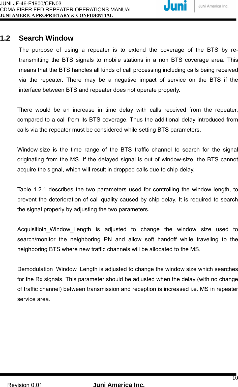
![JUNI JF-46-E1900/CFN03 CDMA FIBER FED REPEATER OPERATIONS MANUAL JUNI AMERICA PROPRIETARY & CONFIDENTIAL Revision 0.01 Juni America Inc. 9 1. Introduction 1.1 Fiber Fed Repeater The JF-46 FFR provides a cost effective solution for cell coverage extension and increased call quality in shadow areas. It is a RF signal transport system that provides long range RF coverage where it is impractical to install a BTS. The JF-46 FFR is designed to be strategically placed to overcome difficult zoning issues by allowing the base stations to remain at a central location while placing antennas at remote locations. RF signals can be transported to remote locations to expand coverage into areas not receiving service or to extend coverage into difficult to reach areas such as canyons, tunnels and underground parking lots and roadways. The JF-46 FFR provides a high-tech, highly-efficient service system which enables high quality communication at low cost, due to the system’s utilization of one optical fiber core between the DHU and RU supporting full duplex transmission of signals for both the DL and UL. Base StationBTSDonorRemoteDL/UL_0Ant.UL_1Ant.Optic Link [FIGURE 1.1.1] SYSTEM CONFIGURATION](https://usermanual.wiki/Inkel/JF46C1900CFN01/User-Guide-1057002-Page-9.png)
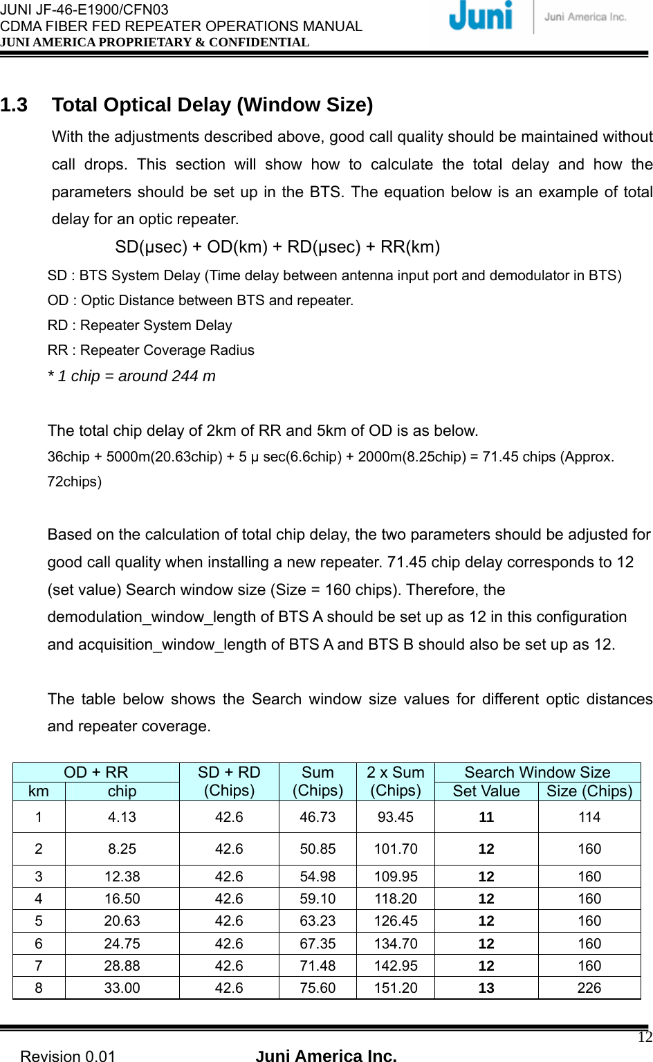
![JUNI JF-46-E1900/CFN03 CDMA FIBER FED REPEATER OPERATIONS MANUAL JUNI AMERICA PROPRIETARY & CONFIDENTIAL Revision 0.01 Juni America Inc. 11 Acquisition_Window_Length Demodulation_Window_Length Purpose Window Range of BTS traffic channel to search for time sync of other BTS Window Range of BTS traffic channel to search multi path referring to the time-offsetUnit 1/8 chip/unit 1/8 chip/unit Remark Use this parameter when traffic channel is changed (Soft hand off) Use this parameter when traffic channel is not changed. (Tracking multi path signal) Notice Too big a Window_size causes increase of time for the mobiles to search for BTS signal. It should be set up with proper values considering time delay. [Table1.2.1] Two Parameters for Search Window Setup Therefore, the two parameters stated can be used to adjust the interface between the BTS and the repeater considering the movement of the MS. Picture 1 shows an example of two window size parameters for the JF-46 repeater application. [FIGURE 1.2.1] HANDOFF BETWEEN BTS AND REPEATER The Demodulation_Window_Length is used to adjust the time sync to compensate the chip delay introduced by the optic core when the MS moves into the repeater coverage area. When the MS travels from the repeater coverage to the BTS B area, Acquisition_Window_Length is used to adjust this time offset differences. With this adjustment, the MS will be able to perform soft handoff from BTS A traffic channel (while in repeater coverage) to the BTS B traffic channel. Without these adjustments, there may have been two call drops while the MS traveled from BTS A to BTS B.](https://usermanual.wiki/Inkel/JF46C1900CFN01/User-Guide-1057002-Page-11.png)
![JUNI JF-46-E1900/CFN03 CDMA FIBER FED REPEATER OPERATIONS MANUAL JUNI AMERICA PROPRIETARY & CONFIDENTIAL Revision 0.01 Juni America Inc. 139 37.13 42.6 79.73 159.45 13 226 10 41.25 42.6 83.85 167.70 13 226 11 45.38 42.6 87.98 175.95 13 226 12 49.50 42.6 92.10 184.20 13 226 13 53.63 42.6 96.23 192.45 13 226 14 57.75 42.6 100.35 200.70 13 226 15 61.88 42.6 104.48 208.95 13 226 16 66.00 42.6 108.60 217.20 14 320 17 70.13 42.6 112.73 225.45 14 320 18 74.25 42.6 116.85 233.70 14 320 19 78.38 42.6 120.98 241.95 14 320 20 82.50 42.6 125.10 250.20 14 320 21 86.63 42.6 129.23 258.45 14 320 22 90.75 42.6 133.35 266.70 14 320 23 94.88 42.6 137.48 274.95 14 320 24 99.00 42.6 141.60 283.20 14 320 25 103.13 42.6 145.73 291.45 14 320 26 107.25 42.6 149.85 299.70 14 320 27 111.38 42.6 153.98 307.95 14 320 28 115.50 42.6 158.10 316.20 15 452 29 119.63 42.6 162.23 324.45 15 452 30 123.75 42.6 166.35 332.70 15 452 [Table1.3.1] Example Table for Search Window Size 1.4 FFR Components The JF-46 FFR system comprises of two main elements, a DHU and RU. [FIGURE 1.4.1] DONOR HUB UNIT ENCLOSURE [FIGURE 1.4.2] REMOTE UNIT](https://usermanual.wiki/Inkel/JF46C1900CFN01/User-Guide-1057002-Page-13.png)
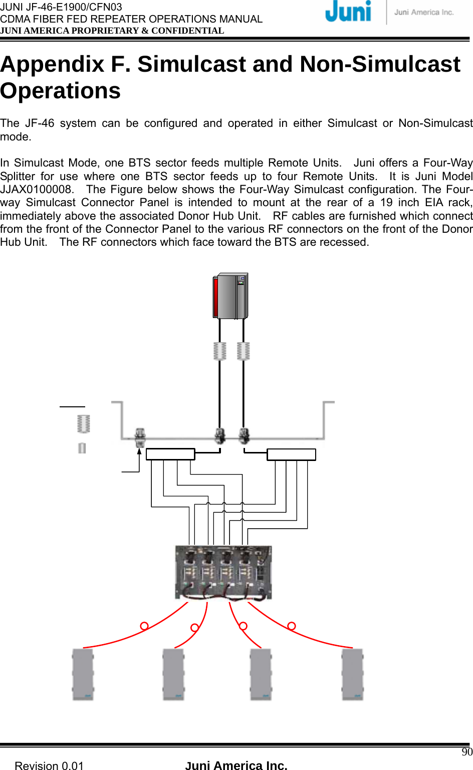
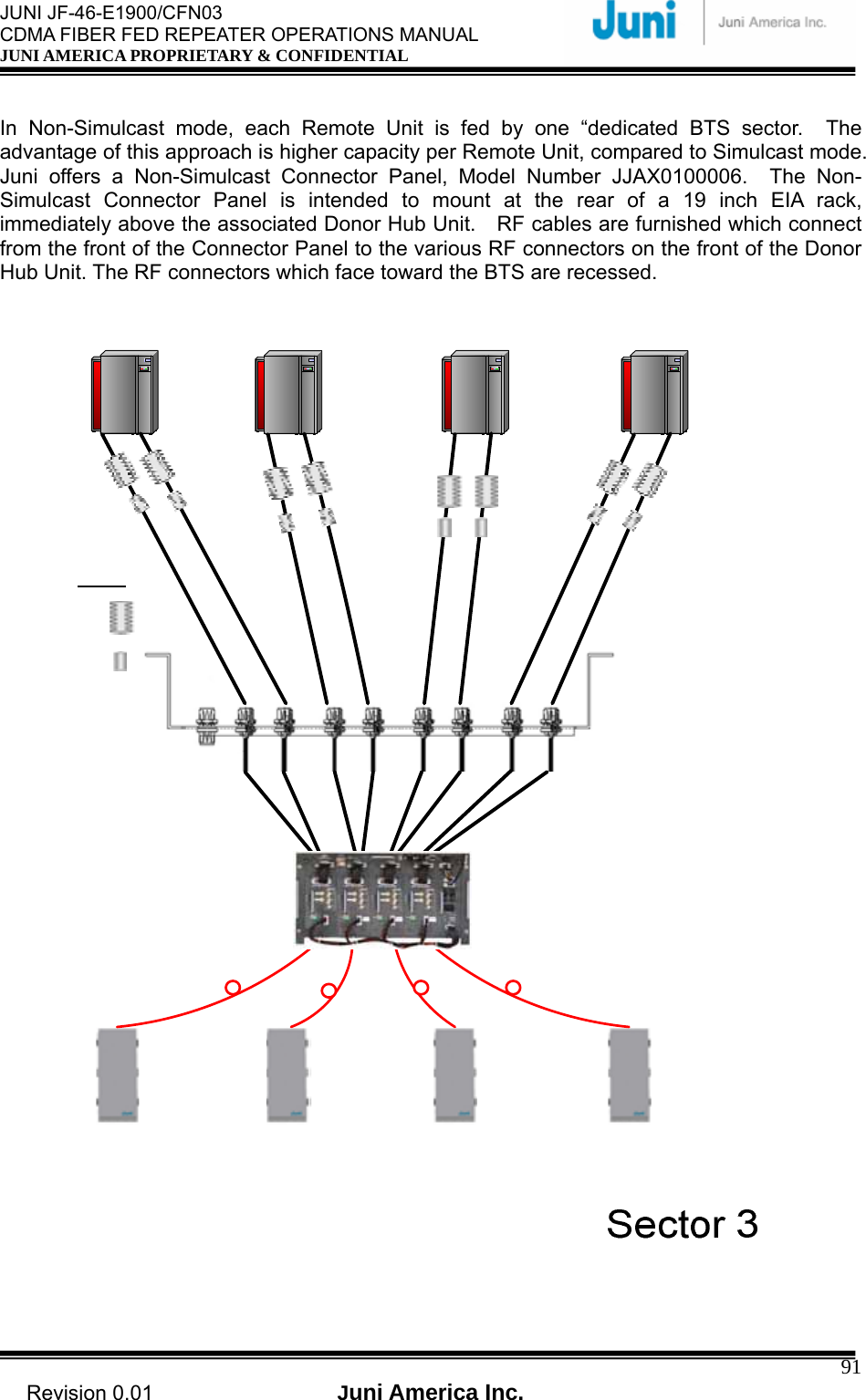
![JUNI JF-46-E1900/CFN03 CDMA FIBER FED REPEATER OPERATIONS MANUAL JUNI AMERICA PROPRIETARY & CONFIDENTIAL Revision 0.01 Juni America Inc. 19 2. System Description 2.1 FFR System The JF-46 FFR is made up of a main Donor Hub Unit (DHU) and a RU. The DHU and RU are divided into modules to allow easy operation and maintenance. It can operate even in the harshest environmental conditions due to its durable IP55-rated weatherproof enclosure. [FIGURE 2.1.1] SYSTEM BLOCK DIAGRAM 2.2 Simulcast Operation Please refer to Figure 2.2.1 for a system block diagram of a Simulcast FFR configuration, where a single BTS sector provides coverage to two Remote Units. This configuration employs two RF Splitter/Combiner units at the RF ports of the Donor Hub Unit which relate to the two Remote Units. On the DL path, the BTS signal is split two ways and feeds two DHU input ports. Similarly, on the UL path, the signals from two DHU RF ports are summed and fed to one port of the BTS.](https://usermanual.wiki/Inkel/JF46C1900CFN01/User-Guide-1057002-Page-19.png)
![JUNI JF-46-E1900/CFN03 CDMA FIBER FED REPEATER OPERATIONS MANUAL JUNI AMERICA PROPRIETARY & CONFIDENTIAL Revision 0.01 Juni America Inc. 20The JF-46 FFR has adequate RF gain margin to support a Splitter/Combiner as shown with loss of up to 10 dB. As a result, a single BTS sector can easily feed 4 or even 8 Remote Units. If more than 4 Remote Units are to be supported, more than one DHU is required since a DHU can support only a maximum of 4 Optic Modules, which drive 4 Remote Units. [FIGURE 2.2.1] SIMULCAST BLOCK DIAGRAM](https://usermanual.wiki/Inkel/JF46C1900CFN01/User-Guide-1057002-Page-20.png)
![JUNI JF-46-E1900/CFN03 CDMA FIBER FED REPEATER OPERATIONS MANUAL JUNI AMERICA PROPRIETARY & CONFIDENTIAL Revision 0.01 Juni America Inc. 212.3 Donor Hub Unit This section describes the main components of the DHU, the functions performed by the components and the user interface. 2.3.1 Donor Hub Unit Enclosure and Shelf [FIGURE 2.3.1] MAIN COMPONENTS OF THE DONOR HUB UNIT ① FAN: Provides ventilation and disperses heat evenly. ② DRCU (Donor Repeater Control Unit): Monitors and controls each internal module. Also monitors and controls the RU by data communication. Monitoring the control and status of all repeaters can only be managed at an administrative level via the internal SNMP agent. ③ OTRU(Optic Transceiver Unit): Converts the RF signal (from the BTS) into an optical signal and transmits the signal to the RU. Conversely, the RU converts the optic signal and transmits it to the BTS. ④ PSU (Power Supply Unit): Converts the input power AC power (115-230VAC, free voltage) into DC+27V, DC+15V, DC +7V and supplies the power to the modules.](https://usermanual.wiki/Inkel/JF46C1900CFN01/User-Guide-1057002-Page-21.png)
![JUNI JF-46-E1900/CFN03 CDMA FIBER FED REPEATER OPERATIONS MANUAL JUNI AMERICA PROPRIETARY & CONFIDENTIAL Revision 0.01 Juni America Inc. 22 [FIGURE 2.3.2] DONOR HUB UNIT SHELF INTERFACE ① CDMA Modem RF Port (Female SMA-Type): An RF cable connects the CDMA wireless modem port on the DRCU to the modem RF port situated on the outside of the enclosure in case of outdoor type. ② Debug and Ethernet port: Ethernet port to allow connection to any PC for debugging via the GUI, allow connection to IP Control Box for SNMP ③ DRCU and SNMP reset Key and LEDs: Hard reset button to restart the DRCU and SNMP agent. LEDs to display the status of the System. ④ DRCU Power switch: Turns the power on/off for the DRCU only. ⑤ Main and battery power switch: Main power switch located on the power supply which provides power to the entire DHU. ⑥ RF in/out port (Female SMA): RF ports on a single optic transceiver supports only one sector. This port is connected to the enclosure with RF cables. ⑦ Monitoring port (Female SMA): Ports used to monitor signals existing within the DHU with a spectrum analyzer or test equipment. ⑧ OTRU Power switch: Turns the power on/off for the OTRU only. ⑨ Optic connector : Connector to where the fiber is connected to.](https://usermanual.wiki/Inkel/JF46C1900CFN01/User-Guide-1057002-Page-22.png)
![JUNI JF-46-E1900/CFN03 CDMA FIBER FED REPEATER OPERATIONS MANUAL JUNI AMERICA PROPRIETARY & CONFIDENTIAL Revision 0.01 Juni America Inc. 23⑩ 1 2 34 4 [FIGURE 2.3.3] DONOR HUB UNIT EXTERNAL CONNECTORS (BOTTOM VIEW) ① CDMA modem RF port (Female N-Type): External Antenna for modem connected to this port. ② Fiber Entrance: The fiber is passed through to connect to the optic transceiver. ③ AC power connector (Female weatherproof MS type): Connectors used for AC powering. The AC power cable is supplied by the manufacturer. ④ RF in/out port (Female N type): Provides connection to the BTS. ⑤ Battery connector (Female weatherproof MS type): Connector for backup battery unit. 2.3.2 Wireless Modem Antenna The technical requirements for the Wireless Modem Antenna are dependent on the specific DHU location and network coverage. If the nearest BTS with a local antenna is nearby the DHU, a 3 dBi Gain Omni antenna should be quite adequate. The Modem Antenna is to be connected to the modem antenna connector on the DHU. In the event the nearest BTS with a local antenna is quite some distance from the DHU, a directional antenna with 10 dBi Gain, aimed at the nearest BTS with the local antenna, is the appropriate modem antenna solution. : Data and power cable](https://usermanual.wiki/Inkel/JF46C1900CFN01/User-Guide-1057002-Page-23.png)
![JUNI JF-46-E1900/CFN03 CDMA FIBER FED REPEATER OPERATIONS MANUAL JUNI AMERICA PROPRIETARY & CONFIDENTIAL Revision 0.01 Juni America Inc. 24 2.4 Remote Unit This section describes the main components of the RU, the functions performed by the components and the user interface. 2.4.1 Remote Unit OPTICAC_IN UL_1DL/UL_0 BATTERY (Max 0.7A)NMS350_IN UL0_INNMS DL_OUTUL1_IN 320 _OUTSPT-JF46Remote_Optic Module31 23445678 8 [FIGURE 2.4.1] MAIN COMPONENTS OF THE REMOTE UNIT ① Remote Optic Module: Converts the optic signal (from DHU) into RF signal. Conversely, it converts the RF signal (from the RU) into an optic signal. ② Duplexer & BPF: Filters out the unwanted signals on the FWD and REV path. ③ FSK Modem: Modem for communications between the DHU and the RU. ④ Low Noise Amplifier (LNA): Performs low noise amplification on received signals.](https://usermanual.wiki/Inkel/JF46C1900CFN01/User-Guide-1057002-Page-24.png)
![JUNI JF-46-E1900/CFN03 CDMA FIBER FED REPEATER OPERATIONS MANUAL JUNI AMERICA PROPRIETARY & CONFIDENTIAL Revision 0.01 Juni America Inc. 262.4.2 Remote Unit Connectors 1BATTERY(Max 0.7A) OPTICAC_IN DL/UL_0 UL_1FANABDCEF2 3 4 56 [FIGURE 2.4.2] REMOTE UNIT EXTERNAL CONNECTORS (BOTTOM VIEW) ① AC power connector: Male AC power connector to allow connection for a female MS3102 Type AC power connector and AC power feeder cable. ② Fiber entrance port: A non metallic liquid tight strain relief is connected to the port with a fiber core fed through the center into the RU. ③ DL/UL0 path in/out port: Female DIN type DL/UL path port making use of a single fiber core for full duplex operation. An antenna is connected to this port to transmit and receive signals. ④ UL1 path input port: Female DIN type Diversity uplink/receive path port to connect a second antenna ⑤ Battery connector: A weatherproof two pin MS connector used to connect an external battery backup unit. ⑥ FAN connector: A weatherproof six pin MS connector used to connect the fan unit.](https://usermanual.wiki/Inkel/JF46C1900CFN01/User-Guide-1057002-Page-26.png)
![JUNI JF-46-E1900/CFN03 CDMA FIBER FED REPEATER OPERATIONS MANUAL JUNI AMERICA PROPRIETARY & CONFIDENTIAL Revision 0.01 Juni America Inc. 30 [FIGURE 3.5.1] OPTICAL FIBER JUMPER CABLE 3.5.4 Weatherproofing Connectors Once all connectors and cables have been configured and assembled, weatherproofing is vital to prevent corrosion due to water ingress which could lead to eventual failure. 1. Making sure that the connector surfaces are clear of residue and dry, firmly tighten the connectors. [FIGURE 3.5.2] CONNECT CABLE TO CONNECTOR [FIGURE 3.5.3] FASTEN CABLE TO CONNECTOR 2. Seal the connector assembly by tightly wrapping Butyl tape over the connection. Two or more layers should be used so that the tape seals the entire connection and extends beyond the connector by about an inch. [FIGURE 3.5.4] WRAP CONNECTION WITH BUTYL TAPE](https://usermanual.wiki/Inkel/JF46C1900CFN01/User-Guide-1057002-Page-30.png)
![JUNI JF-46-E1900/CFN03 CDMA FIBER FED REPEATER OPERATIONS MANUAL JUNI AMERICA PROPRIETARY & CONFIDENTIAL Revision 0.01 Juni America Inc. 31 3. Tightly wrap electrical tape around the existing Butyl tape making sure to also extend one inch beyond the Butyl tape to completely envelop the tape and connector. [FIGURE 3.5.5] WRAP OVER BUTYL TAPE WITH ELECTRIC TAPE 3.5.5 Donor Unit Eye Bolts There are four eye bolt tapped holes located at the top of the DHU as shown below. The length of the tapped hole is 0.97 inches or 25mm. The customer supplied ¼” 20UNC eye bolts may be used to assist in hoisting the DHU above the ground for wall or pole mount solutions. Ensure that the eyebolts are securely attached to the top of the DHU. Check that the cables used to lift the DHU is securely fastened to the eyebolts before it is lifted. [FIGURE 3.5.6] DONOR UNIT EYE BOLT PATTERNS](https://usermanual.wiki/Inkel/JF46C1900CFN01/User-Guide-1057002-Page-31.png)
![JUNI JF-46-E1900/CFN03 CDMA FIBER FED REPEATER OPERATIONS MANUAL JUNI AMERICA PROPRIETARY & CONFIDENTIAL Revision 0.01 Juni America Inc. 32 3.5.6 Donor Unit Standard Wall Mount Guide The DHU is capable of being wall mounted. There are two horizontal panels protruding slightly behind the DHU, with holes along the panel to allow bolts and nuts to be fastened. The wall mount holes will accommodate bolt diameters up to a maximum of 0.4 inches. Drill holes in the wall or area in which it is to be installed to match the mounting holes on the panels. Attach the DHU to the wall using the appropriate fastening method. The figure below displays the positioning and size of the wall mount holes. [FIGURE 3.5.7] DONOR HUB UNIT WALL MOUNTING](https://usermanual.wiki/Inkel/JF46C1900CFN01/User-Guide-1057002-Page-32.png)
![JUNI JF-46-E1900/CFN03 CDMA FIBER FED REPEATER OPERATIONS MANUAL JUNI AMERICA PROPRIETARY & CONFIDENTIAL Revision 0.01 Juni America Inc. 33 3.5.7 Remote Unit Eye Bolts There are two eye bolt tapped holes located at the top of the RU which is located next to the fan compartment. The length of the tapped hole is 0.7 inches or 18mm. The customer supplied ¼” 20UNC eye bolts may be used to assist in hoisting the RU above the ground for wall or pole mount solutions. Prior to using the eyebolts, ensure that the three eyebolts are securely attached to the top of the RU. Check that the cables used to lift the DHU is securely fastened to the eyebolts before it is lifted. [FIGURE 3.5.8] REMOTE UNIT EYE BOLT PATTERN 3.5.8 Remote Unit Standard Wall Mount Guide The RU is capable of being wall mounted. There are two horizontal panels extending from the body of the RU at the top and bottom with holes along the panel to allow bolts and nuts to be fastened. The wall mount holes will accommodate bolt diameters up to a maximum of 0.39 inches. Drill holes in the wall or area in which it is to be installed, to match the mounting holes on the panels. Attach the RU to the wall using the appropriate fastening method. The figure below displays the positioning and size of the wall mount holes.](https://usermanual.wiki/Inkel/JF46C1900CFN01/User-Guide-1057002-Page-33.png)
![JUNI JF-46-E1900/CFN03 CDMA FIBER FED REPEATER OPERATIONS MANUAL JUNI AMERICA PROPRIETARY & CONFIDENTIAL Revision 0.01 Juni America Inc. 34 [FIGURE 3.5.9] REMOTE UNIT WALL MOUNTING](https://usermanual.wiki/Inkel/JF46C1900CFN01/User-Guide-1057002-Page-34.png)
![JUNI JF-46-E1900/CFN03 CDMA FIBER FED REPEATER OPERATIONS MANUAL JUNI AMERICA PROPRIETARY & CONFIDENTIAL Revision 0.01 Juni America Inc. 353.5.9 AC Cables and Connectors Installation Guide Please follow the procedure below to safely install an external power supply to the DHU and RU. 1. Check the line power switch of the power supply to ensure that it is OFF. 2. Install a MS3102 Female type AC connector into the chassis connector located on the bottom of the Power Supply. 3. Place #6 copper ground wire into the ground lug located on the bottom of the cabinet. [FIGURE 3.5.10] STEP 1 4. Route and attach the ground wire according to local electrical codes. 5. Install an approved 20 amp high magnetic circuit breaker on the input power side of the power supply. 6. Install a conduit into the opening on the bottom and attach line power in accordance with local electrical codes. The barrier strip is wired with the hot leg at the top. The bottom connector is chassis ground.](https://usermanual.wiki/Inkel/JF46C1900CFN01/User-Guide-1057002-Page-35.png)
![JUNI JF-46-E1900/CFN03 CDMA FIBER FED REPEATER OPERATIONS MANUAL JUNI AMERICA PROPRIETARY & CONFIDENTIAL Revision 0.01 Juni America Inc. 37 [FIGURE 3.5.11] CABLE CONNECTIONS ON THE DHU (FRONT VIEW) [FIGURE 3.5.12] CABLE CONNECTIONS ON THE DHU (BOTTOM VIEW) Fiber Optic Cable Passed Through DL1/UL1 RF Port from BTS DL0/UL0 RF Port from BTS AC Input Modem Antenna Connection Ground Ground](https://usermanual.wiki/Inkel/JF46C1900CFN01/User-Guide-1057002-Page-37.png)
![JUNI JF-46-E1900/CFN03 CDMA FIBER FED REPEATER OPERATIONS MANUAL JUNI AMERICA PROPRIETARY & CONFIDENTIAL Revision 0.01 Juni America Inc. 39OPTICAC_IN UL_1DL/UL_0 BATTERY(Max 0.7A)NMS350_IN UL0_INNMS DL_OUTUL1_IN 320_OUTSPT-JF46Remote_Optic Module3Fiber Optic Cable Passed ThroughAC InputBattery CableUL_1 RF PortDL/UL_0 RF Port [FIGURE 3.5.13] CABLE CONNECTIONS FOR THE REMOTE UNIT (TOP VIEW) GroundBATTERY(Max 0.7A) OPTICAC_IN DL/UL_0 UL_1FANABDCEFFiber Optic Cable Passed ThroughAC Input Battery CableUL_1 RF PortDL/UL_0 RF PortGround [FIGURE 3.5.14] CABLE CONNECTIONS FOR THE REMOTE UNIT (BOTTOM VIEW)](https://usermanual.wiki/Inkel/JF46C1900CFN01/User-Guide-1057002-Page-39.png)
![JUNI JF-46-E1900/CFN03 CDMA FIBER FED REPEATER OPERATIONS MANUAL JUNI AMERICA PROPRIETARY & CONFIDENTIAL Revision 0.01 Juni America Inc. 403.5.12 Operations Tests This section provides test procedures for the uplink and downlink required to be undertaken in order to set up the JF-46 for optimal service. 3.5.12.1 Optic Cable Loss Test Connect the system as shown below: [FIGURE 3.5.15] CONNECTION TO PERFORM OPTIC CABLE LOSS TEST Check optic cable loss by using an optic power meter or reflectometer 1. With the DHU on, connect the power meter to the optic module of the RU and measure the Forward (1510nm) output level. If the optic input level exceeds +7dBm, check the DHU optic module. 2. If the optic loss is greater than –8dBo (on the basis of 1510nm, optic loss = donor output optic power – remote input optic power) and the optic cable length between the DHU and RU is less than 15 miles, check for faults in the PD (Photo Diode) or check the optic cable. 3. If the optic loss is lesser than –2dBo (on the basis of 1510nm, optic loss = donor output optic power – remote input optic power), add the optic jumper cable(2dBo). 4. If a PD fault has occurred, inspect the optic input level and check the optic line. Clean the optic connector and if the fault is still existent, contact Juni technical support. * Reference Optic cable loss is 0.25dB/km at 1510nm, and connection loss is 0.4dB/connector. The total optic loss due to the connector is about 1 to 2dB. (0.4dB ×2 (connector) = approx 1dB)](https://usermanual.wiki/Inkel/JF46C1900CFN01/User-Guide-1057002-Page-40.png)
![JUNI JF-46-E1900/CFN03 CDMA FIBER FED REPEATER OPERATIONS MANUAL JUNI AMERICA PROPRIETARY & CONFIDENTIAL Revision 0.01 Juni America Inc. 42 [FIGURE 3.5.16] ONE CARRIER TOTAL OUTPUT POWER OF +45DBM](https://usermanual.wiki/Inkel/JF46C1900CFN01/User-Guide-1057002-Page-42.png)
![JUNI JF-46-E1900/CFN03 CDMA FIBER FED REPEATER OPERATIONS MANUAL JUNI AMERICA PROPRIETARY & CONFIDENTIAL Revision 0.01 Juni America Inc. 43 [FIGURE 3.5.17] TWO CARRIER TOTAL OUTPUT POWER VALUE OF +46DBM](https://usermanual.wiki/Inkel/JF46C1900CFN01/User-Guide-1057002-Page-43.png)
![JUNI JF-46-E1900/CFN03 CDMA FIBER FED REPEATER OPERATIONS MANUAL JUNI AMERICA PROPRIETARY & CONFIDENTIAL Revision 0.01 Juni America Inc. 443.5.13.1 Setup for DL Gain The procedures provided below can be used to fine-tune the DHU and RU DL settings to obtain the desired RU Pilot Power output. a. Refer to Figure 3.5.20 below. Set up the BTS for Pilot-only transmission. Verify with a Power Meter or Spectrum Analyzer that the DL input power level to the DHU (to be connected at the DL0/UL0 port of the DHU) is appropriate, given the BTS Pilot-only output power shown in the table and External Loss value. b. Turn on the LPA with the GUI c. While monitoring the forward output power measurement function of the GUI (and optionally while measuring the Remote Unit RF output using Power Attenuator and Spectrum Analyzer or Power Meter, adjust the Remote DL ATT setting to obtain the desired exact RU RF output value shown above. Caution: ● The power attenuator is needs to be rated at >500W. Using a lower rating power attenuator can fail and cause damage to the spectrum analyzer. d. Turn off the LPA with the GUI. e. Disconnect the Power Attenuator and Spectrum Analyzer or Power Meter. f. This completes the DL setup. Note: The Maximum RU output power should not exceed +46 dBm or 40 watts composite during operation to prevent damage to the FFR. [FIGURE 3.5.18] CONNECTION TO SET UP DL GAIN](https://usermanual.wiki/Inkel/JF46C1900CFN01/User-Guide-1057002-Page-44.png)
![JUNI JF-46-E1900/CFN03 CDMA FIBER FED REPEATER OPERATIONS MANUAL JUNI AMERICA PROPRIETARY & CONFIDENTIAL Revision 0.01 Juni America Inc. 453.5.13.2 Setup for UL Gain The procedures provided below can OPTIONALLY be used to fine-tune the DHU and RU UL settings to obtain the exact desired UL Gain. a. Refer to Figure 3.5.21. Connect a Spectrum Analyzer to the DL0/UL0 port of the DHU (Span: 5 MHz, Amplitude Offset = measurement cable loss) b. Inject an Uplink input signal of -95 dBm at the DL/UL_0 port of the RU, and check the output level on the Spectrum Analyzer. c. Based on the above measurements, adjust the Donor UL0 ATT control to obtain an output power value of 32 dB, which corresponds to 0 dB overall Gain with 32 dB External Loss d. Repeat the above procedure for the DL1/UL1 port of the DHU, DL/UL_1 port of the RU, and Donor UL1 ATT control. e. This completes the UL setup. [FIGURE 3.5.19] CONNECTION TO SET UP UL GAIN Note: The procedure is the same for the receive diversity 3.5.13.3 Caution Items ● When adjusting the forward gain, start from the minimum gain setting. ● Max. Output Power should not exceed 40W (about +46dBm), ● When adjusting output levels while monitoring the CDMA test equipments, input the appropriate offset level in the Spectrum Analyzer considering the Cable Loss. (offset value = coupling value + measured cable loss)](https://usermanual.wiki/Inkel/JF46C1900CFN01/User-Guide-1057002-Page-45.png)
![JUNI JF-46-E1900/CFN03 CDMA FIBER FED REPEATER OPERATIONS MANUAL JUNI AMERICA PROPRIETARY & CONFIDENTIAL Revision 0.01 Juni America Inc. 49 4.2.2 WEB GUI Connection 1) Using RJ-45 Ethernet cable, connect from LMT port on the front of the Donor unit to Ethernet port of your PC. 2) First we need to find the TCP/IP properties window. Open the control panel and click the “Network Connections” icon. [FIGURE 4.2.1] OPEN THE CONTROL PANEL 3) The Network connections window will open. All of your available network connections will be listed. I only have one network interface listed, which is my Local Area Network (LAN) card. You could have several options listed here both physical connections and virtual. For example if you had a wireless network car, and a wired network card, you would see both of these listed. An example of a virtual connection, meaning that there is no physical adapter, would be a Virtual Private Network (VPN). VPN’s are well beyond the scope of the tutorial, but I wanted to give you an example of the icons that you may see. My listing is pictured below. [FIGURE 4.2.2] NETWORK CONNECTIONS](https://usermanual.wiki/Inkel/JF46C1900CFN01/User-Guide-1057002-Page-49.png)
![JUNI JF-46-E1900/CFN03 CDMA FIBER FED REPEATER OPERATIONS MANUAL JUNI AMERICA PROPRIETARY & CONFIDENTIAL Revision 0.01 Juni America Inc. 50 4) I will be explaining the settings of a standard wired connection. Right click on your Local Area Network connection and select properties. [FIGURE 4.2.3] NETWORK PROPERTIES 5) In the Local Area Connection Properties window find the box that reads “This connection uses the following items.” Use the scroll bar to locate the “Internet Properties (TCP/IP)” then highlight it and click the properties button. [FIGURE 4.2.4] INTERNET PROTOCOL(TCP/IP)](https://usermanual.wiki/Inkel/JF46C1900CFN01/User-Guide-1057002-Page-50.png)
![JUNI JF-46-E1900/CFN03 CDMA FIBER FED REPEATER OPERATIONS MANUAL JUNI AMERICA PROPRIETARY & CONFIDENTIAL Revision 0.01 Juni America Inc. 51 6) When the options “Obtain an IP address automatically” and “Obtain DNS server address automatically are selected, your computer will be set to operating using DHCP. DHCP stands for Dynamic Host Configuration Protocol [FIGURE 4.2.5] INTERNET PROTOCOL(TCP/IP) PROPERTIES 7) Run “Internet Explorer” and type the IP address as below. LMT Default Address: 192.168.0.2 [FIGURE 4.2.6] DEFAULT ADDRESS](https://usermanual.wiki/Inkel/JF46C1900CFN01/User-Guide-1057002-Page-51.png)
![JUNI JF-46-E1900/CFN03 CDMA FIBER FED REPEATER OPERATIONS MANUAL JUNI AMERICA PROPRIETARY & CONFIDENTIAL Revision 0.01 Juni America Inc. 52 4.2.3 Repeater Log In When you see the webpage as below, type the proper user ID and password. The user ID has three categories such as administrator, operator and viewer. Depending on user ID, the display of window will be different. [FIGURE 4.2.7] REPEATER GUI LOG IN 4.2.4 Default Usernames and Passwords ENTER USER NAME AND PASSWORD HERE.](https://usermanual.wiki/Inkel/JF46C1900CFN01/User-Guide-1057002-Page-52.png)
![JUNI JF-46-E1900/CFN03 CDMA FIBER FED REPEATER OPERATIONS MANUAL JUNI AMERICA PROPRIETARY & CONFIDENTIAL Revision 0.01 Juni America Inc. 53 4.2.5 Initial Window When you log in, the initial screen is as below. [FIGURE 4.2.8] INITIAL WINDOW 1) System Configuration:: It automatically displays whether OTRU has been installed or not. 2) System Information: It displays model name, system type and GUI version. 3) Network Information: It displays WIP address and LIP address.](https://usermanual.wiki/Inkel/JF46C1900CFN01/User-Guide-1057002-Page-53.png)
![JUNI JF-46-E1900/CFN03 CDMA FIBER FED REPEATER OPERATIONS MANUAL JUNI AMERICA PROPRIETARY & CONFIDENTIAL Revision 0.01 Juni America Inc. 54 4.2.6 Account Window Figure 4.2.3 shows the Account window. There are three user IDs for administrator, operator and viewer. The administrator can control and monitor all the functions. And the administrator can also create and delete user IDs and passwords of operator and viewer. The administrator is allowed to create five accounts for operator and two accounts for viewer. [FIGURE 4.2.9] ACCOUNT WINDOW](https://usermanual.wiki/Inkel/JF46C1900CFN01/User-Guide-1057002-Page-54.png)
![JUNI JF-46-E1900/CFN03 CDMA FIBER FED REPEATER OPERATIONS MANUAL JUNI AMERICA PROPRIETARY & CONFIDENTIAL Revision 0.01 Juni America Inc. 55 4.2.7 Clock Window [FIGURE 4.2.10] CLOCK WINDOW](https://usermanual.wiki/Inkel/JF46C1900CFN01/User-Guide-1057002-Page-55.png)
![JUNI JF-46-E1900/CFN03 CDMA FIBER FED REPEATER OPERATIONS MANUAL JUNI AMERICA PROPRIETARY & CONFIDENTIAL Revision 0.01 Juni America Inc. 56 4.2.8 Network Window This menu is for setting network configuration. Using this menu, you can configure TCP/IP for each interface and SNMP items. [FIGURE 4.2.11] NETWORK WINDOW 4.2.9 Control Window To view the status of installed repeaters, double click on the desired repeater in Figure 4.2.4 to bring up the Status and Control Window. This can also be done by right-clicking on the desired repeater and selecting the “Status & Control” command as shown in Figure 4.2.6.](https://usermanual.wiki/Inkel/JF46C1900CFN01/User-Guide-1057002-Page-56.png)
![JUNI JF-46-E1900/CFN03 CDMA FIBER FED REPEATER OPERATIONS MANUAL JUNI AMERICA PROPRIETARY & CONFIDENTIAL Revision 0.01 Juni America Inc. 57 4.2.9.1 Donor Control Window [FIGURE 4.2.12] DONOR CONTROL WINDOW](https://usermanual.wiki/Inkel/JF46C1900CFN01/User-Guide-1057002-Page-57.png)
![JUNI JF-46-E1900/CFN03 CDMA FIBER FED REPEATER OPERATIONS MANUAL JUNI AMERICA PROPRIETARY & CONFIDENTIAL Revision 0.01 Juni America Inc. 58 4.2.9.2 OTRU Control Window [FIGURE 4.2.13] OTRU CONTROL WINDOW](https://usermanual.wiki/Inkel/JF46C1900CFN01/User-Guide-1057002-Page-58.png)
![JUNI JF-46-E1900/CFN03 CDMA FIBER FED REPEATER OPERATIONS MANUAL JUNI AMERICA PROPRIETARY & CONFIDENTIAL Revision 0.01 Juni America Inc. 59 4.2.9.3 Remote Control Window [FIGURE 4.2.14] REMOTE CONTROL WINDOW](https://usermanual.wiki/Inkel/JF46C1900CFN01/User-Guide-1057002-Page-59.png)
![JUNI JF-46-E1900/CFN03 CDMA FIBER FED REPEATER OPERATIONS MANUAL JUNI AMERICA PROPRIETARY & CONFIDENTIAL Revision 0.01 Juni America Inc. 60normal 5MHz normal 15MHz normal 20MHz 5+15 15+5A1 A A,D A1+A2 D+B3 E+F A1+(A3,D,B1) A+B1A2 A2,A3,D A2,A3,D,B1 A1+A3 D+E E+C1 A2+(D,B1,B2) (A2,A3,D)+B2A3 A3,D,B1 A3,D,B1,B2 A1+D B1+B2 E+C2 A3+ B (A3,D,B1)+B3D D,B1,B2 D,B A1+B1 B1+B3 E+C3 D+(B2,B3,E) (D,B1,B2)+EB1 B B,E A2+A3 B1+E F+C1 B1+(B3,E,F) B+FB2 B2,B3,E B2,B3,E,F A2+D B1+F F+C2 B2+(E,F,C1) (B2,B3,E)+C1B3 B3,E,F B3,E,F,C1 A2+B1 B2+B3 F+C3 B3+(F,C1,C2) (B3,E,F)+C2E E,F,C1 E,F,C1,C2 A2+B2 B2+E F+G E+C (E,F,C1)+C3F F,C1,C2 F,C A3+D B2+F C1+C2 F+(C2,C3,G) (F+C1,C2)+G)C1 C C,G A 3+B1 B2+C1 C1+C3C2 C2,C3,G A3+B2 B3+E C1+GC3 A 3+B3 B3+F C2+C3G D+B1 B3+C1 C2+GD+B2 B3+C2 C3+G5+5 [Table 4.2.1] 94 Possible Frequency Band Combinations Band Frequency A1 1850 to 1855 MHz A2 1855 to 1860 MHz A3 1860 to 1865 MHz D 1865 to 1870 MHz B1 1870 to 1875 MHz B2 1875 to 1880 MHz B3 1880 to 1885 MHz E 1885 to 1890 MHz F 1890 to 1895 MHz C1 1895 to 1900 MHz C2 1900 to 1905 MHz C3 1905 to 1910 MHz G 1910 to 1915 MHz [Table 4.2.2] Frequency band ranges corresponding to Table 4.2.1 Note: Frequencies C1, C2, C3 are identical to FCC’s C3, C4, and C5.](https://usermanual.wiki/Inkel/JF46C1900CFN01/User-Guide-1057002-Page-60.png)
![JUNI JF-46-E1900/CFN03 CDMA FIBER FED REPEATER OPERATIONS MANUAL JUNI AMERICA PROPRIETARY & CONFIDENTIAL Revision 0.01 Juni America Inc. 61 4.2.10 Advanced Window [FIGURE 4.2.15] ADVANCED WINDOW](https://usermanual.wiki/Inkel/JF46C1900CFN01/User-Guide-1057002-Page-61.png)
![JUNI JF-46-E1900/CFN03 CDMA FIBER FED REPEATER OPERATIONS MANUAL JUNI AMERICA PROPRIETARY & CONFIDENTIAL Revision 0.01 Juni America Inc. 62 4.2.11 Upload Window [FIGURE 4.2.16] UPLOAD WINDOW 4.2.12 SNMP History Window [FIGURE 4.2.17] SNMP HISTORY WINDOW](https://usermanual.wiki/Inkel/JF46C1900CFN01/User-Guide-1057002-Page-62.png)
![JUNI JF-46-E1900/CFN03 CDMA FIBER FED REPEATER OPERATIONS MANUAL JUNI AMERICA PROPRIETARY & CONFIDENTIAL Revision 0.01 Juni America Inc. 63 4.2.13 Alarm History Window [FIGURE 4.2.18] ALARM HISTORY WINDOW 4.2.14 Alarm Mask Window [FIGURE 4.2.19] ALARM MASK WINDOW](https://usermanual.wiki/Inkel/JF46C1900CFN01/User-Guide-1057002-Page-63.png)
![JUNI JF-46-E1900/CFN03 CDMA FIBER FED REPEATER OPERATIONS MANUAL JUNI AMERICA PROPRIETARY & CONFIDENTIAL Revision 0.01 Juni America Inc. 64 4.2.15 Reboot Window [FIGURE 4.2.20] REBOOT WINDOW](https://usermanual.wiki/Inkel/JF46C1900CFN01/User-Guide-1057002-Page-64.png)
![JUNI JF-46-E1900/CFN03 CDMA FIBER FED REPEATER OPERATIONS MANUAL JUNI AMERICA PROPRIETARY & CONFIDENTIAL Revision 0.01 Juni America Inc. 65 4.3 Network Menu This menu is for setting network configuration. Using this menu, you can configure TCP/IP for each interface and SNMP items. [FIGURE 4.3.1] NETWORK MENU 4.3.1 SNMP Configuration 4.3.1.1 Introduction The DHU utilizes a wireless CDMA modem connected to the SNMP agent to transmit SNMP TRAPs and INFORMs to a central Sprint EMS (Element Management Server) on the Sprint private network. The TRAPs, or commonly referred to as a heartbeat, are sent at an interval of every 1 ~ 120 minutes and is a method of notifying the EMS that the repeater is still connected to the network and is functioning correctly. INFORMs are transmitted when an alarm at a RU occurs. The INFORM is sent to the EMS providing information on the type of alarm that has occurred and the repeater it originates from.](https://usermanual.wiki/Inkel/JF46C1900CFN01/User-Guide-1057002-Page-65.png)
![JUNI JF-46-E1900/CFN03 CDMA FIBER FED REPEATER OPERATIONS MANUAL JUNI AMERICA PROPRIETARY & CONFIDENTIAL Revision 0.01 Juni America Inc. 66 [FIGURE 4.3.2] SNMP OPERATION OVERVIEW 4.3.1.2 Trap Server IP Address Set up Set up EMS IP address that belongs to Sprint Private Network in order to transmit messages for SNMP trap and inform. [FIGURE 4.3.3] TRAP SERVER IP ADDRESS 4.3.1.3 Heartbeat Interval Set up Set up the heartbeat interval for transmitting to EMS. [FIGURE 4.3.4] HEARTBEAT INTERVAL](https://usermanual.wiki/Inkel/JF46C1900CFN01/User-Guide-1057002-Page-66.png)
![JUNI JF-46-E1900/CFN03 CDMA FIBER FED REPEATER OPERATIONS MANUAL JUNI AMERICA PROPRIETARY & CONFIDENTIAL Revision 0.01 Juni America Inc. 67 4.3.2 Network Set up 4.3.2.1 Wireless Network Information The information shows the interface between CDMA modem and Sprint network. This information is automatically assigned from DHCP server throughout CDMA modem. If interface information shows “0.0.0.0,” there is communication problem between CDMA modem and Sprint network. In this case, you cannot send any information of heartbeat and alarm and it is not possible to connect Web GUI throughout Sprint Network. [FIGURE 4.3.5] WIRELESS NETWORK INFORMATION 4.3.2.2 Local Network Information The user can check the information about network information of LMT port that the user can directly connect at the site where the repeater is installed. In order to use this interface, the user must set DHCP server to be enable and set the “Internet Protocol Option” as “Obtain an IP address automatically” as described on Section 4.2.2. [FIGURE 4.3.6] LOCAL NETWORK INFORMATION 1) DHCP Server: Sets up for DHCP to be “Enable” or “Disable.” If the user sets up as “Disable,” the user must manually set up proper IP address to connect to the Web GUI on user’s PC.](https://usermanual.wiki/Inkel/JF46C1900CFN01/User-Guide-1057002-Page-67.png)
![JUNI JF-46-E1900/CFN03 CDMA FIBER FED REPEATER OPERATIONS MANUAL JUNI AMERICA PROPRIETARY & CONFIDENTIAL Revision 0.01 Juni America Inc. 682) Static IP Address: If the IP address is set up for LMT port, the IP address is used for connecting to Web GUI on web browser throughout Internet Explorer. If the user doesn’t figure out the modification information, it can be checked on the “Local Area Connection Status” as Figure 4.3.2.2 below. 3) Subnet Mask: Sub Network Mask for LMT port. 4) Gateway: Gateway for LMT port. The user doesn’t usually set this Gateway up. [FIGURE 4.3.7] SNMP OPERATION OVERVIEW](https://usermanual.wiki/Inkel/JF46C1900CFN01/User-Guide-1057002-Page-68.png)
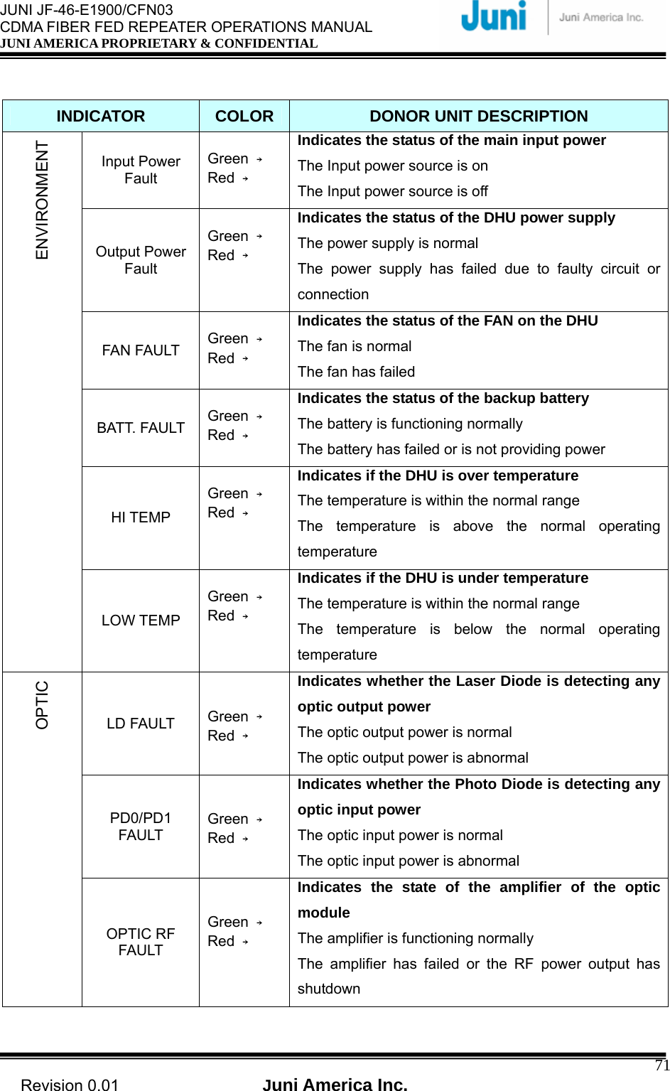
![JUNI JF-46-E1900/CFN03 CDMA FIBER FED REPEATER OPERATIONS MANUAL JUNI AMERICA PROPRIETARY & CONFIDENTIAL Revision 0.01 Juni America Inc. 72DL DL RF FAULT Green → Red → Indicates the state of the downlink amplifier The amplifier is functioning normally The amplifier has failed or the RF power output has shutdown UL UL RF FAULT Green → Red → Indicates the state of the downlink amplifier The amplifier is functioning normally The amplifier has failed or the RF power output has shutdown [Table 5.2.1] Donor Unit Alarm Items](https://usermanual.wiki/Inkel/JF46C1900CFN01/User-Guide-1057002-Page-72.png)
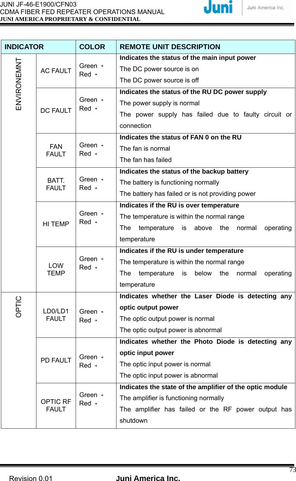
![JUNI JF-46-E1900/CFN03 CDMA FIBER FED REPEATER OPERATIONS MANUAL JUNI AMERICA PROPRIETARY & CONFIDENTIAL Revision 0.01 Juni America Inc. 74OVER POWER Green → Red → Indicates whether the PA is above the optimal power level The power level is below the normal operating level The power level is above the normal operating level OVER TEMP. Green → Red → Indicates if the DHU is over temperature The RU is operating at correct temperature The RU is above the normal operating temperature VSWR Green → Red → Indicates if the power amplifier VSWR is above or below the threshold The VSWR is below the threshold The VSWR is above the threshold DC FAIL Green → Red → Indicates the status of the RU DC power supply The RU power supply is operating normally The power supply has failed due to fault in circuitry or connection POWER AMPLIFIER (PA) LINK FAIL Green → Red → Indicates the link status between the RSM and PA The link is operating normally The link between the RSM and PA is broken. Check modules and link connections HI POWER Green → Red → Indicates if the PA is above the normal operating power level The power level is within the normal range The power level is above the normal threshold DL LO POWER Green → Red → Indicates if the PA is below the normal operating power level The power level is within the normal range The power level is below the normal threshold UL UL0/1 RF Fault Green →Red → Indicates the status of the UL0 Low Noise Amplifier The UL0/1 LNA is normal The UL0/1 LNA is not functioning correctly. Check the module gain [Table 5.2.2] Remote Unit Alarm Items](https://usermanual.wiki/Inkel/JF46C1900CFN01/User-Guide-1057002-Page-74.png)
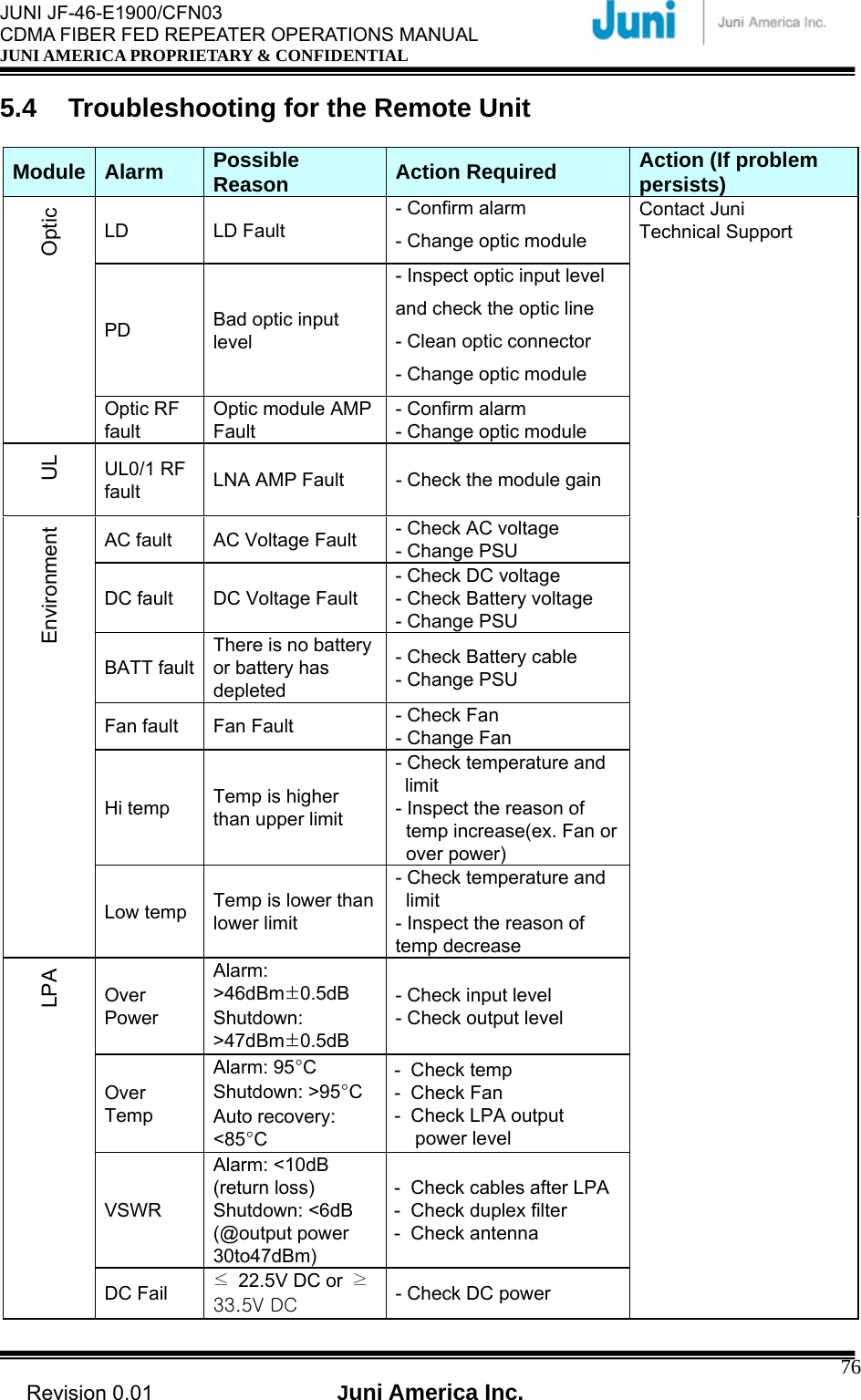
![JUNI JF-46-E1900/CFN03 CDMA FIBER FED REPEATER OPERATIONS MANUAL JUNI AMERICA PROPRIETARY & CONFIDENTIAL Revision 0.01 Juni America Inc. 75 5.3 Troubleshooting for the Donor Unit Module Alarm Possible Reason Action Required Action (If problem persists) LD LD Fault - Confirm alarm - Change optic module PD Bad optic input level - Inspect optic input level and check the optic line - Clean optic connector - Change optic module Optic Optic RF fault Optic module AMP Fault - Confirm alarm - Change optic module DL RF fault DL path AMP Fault - Check the module gain DL/UL UL RF fault UL path AMP Fault - Check the module gain Input power fault Input Voltage Fault - Check Input voltage - Replace PSU output power fault Output Voltage Fault - Check Output voltage - Check Battery voltage - Replace PSU BATT faultThere is no battery or battery has depleted - Check Battery cable - Replace PSU Fan fault Fan Fault - Check Fan - Replace Fan Hi temp Temp is higher than upper limit - Check temperature and limit - Inspect the reason of temp increase (e.g. fan or over power) Environment Low temp Temp is lower than lower limit - Check temperature and limit - Inspect the reason of temp decrease Contact Juni Technical Support [Table 5.3.1] Donor Unit Trouble Shooting Guide](https://usermanual.wiki/Inkel/JF46C1900CFN01/User-Guide-1057002-Page-75.png)
![JUNI JF-46-E1900/CFN03 CDMA FIBER FED REPEATER OPERATIONS MANUAL JUNI AMERICA PROPRIETARY & CONFIDENTIAL Revision 0.01 Juni America Inc. 77Link Fail No communication with RRCU - Check Data Cable - Check connector PA on/off LPA power off - Check LPA Hi Power Output power is higher than upper limit - Check output power level- Check setting limit Forward Output Power Lo Power Output power is lower than lower limit - Check output power level- Check setting limit [Table 5.4.1] Remote Unit Trouble Shooting Guide](https://usermanual.wiki/Inkel/JF46C1900CFN01/User-Guide-1057002-Page-77.png)
![JUNI JF-46-E1900/CFN03 CDMA FIBER FED REPEATER OPERATIONS MANUAL JUNI AMERICA PROPRIETARY & CONFIDENTIAL Revision 0.01 Juni America Inc. 79 Appendix A. JF-46 Mechanical Packaging 1. Donor Unit [FIGURE A1.1] DONOR UNIT](https://usermanual.wiki/Inkel/JF46C1900CFN01/User-Guide-1057002-Page-79.png)
![JUNI JF-46-E1900/CFN03 CDMA FIBER FED REPEATER OPERATIONS MANUAL JUNI AMERICA PROPRIETARY & CONFIDENTIAL Revision 0.01 Juni America Inc. 80 [FIGURE A1.2] DONOR UNIT WALL MOUNTING [FIGURE A1.3] DONOR UNIT FRONT VIEW](https://usermanual.wiki/Inkel/JF46C1900CFN01/User-Guide-1057002-Page-80.png)
![JUNI JF-46-E1900/CFN03 CDMA FIBER FED REPEATER OPERATIONS MANUAL JUNI AMERICA PROPRIETARY & CONFIDENTIAL Revision 0.01 Juni America Inc. 81 [FIGURE A1.4] DONOR SHELF AND OPTIC MODULE](https://usermanual.wiki/Inkel/JF46C1900CFN01/User-Guide-1057002-Page-81.png)
![JUNI JF-46-E1900/CFN03 CDMA FIBER FED REPEATER OPERATIONS MANUAL JUNI AMERICA PROPRIETARY & CONFIDENTIAL Revision 0.01 Juni America Inc. 82 2. Remote Unit [FIGURE A2.1] REMOTE UNIT WALL MOUNTING](https://usermanual.wiki/Inkel/JF46C1900CFN01/User-Guide-1057002-Page-82.png)
![JUNI JF-46-E1900/CFN03 CDMA FIBER FED REPEATER OPERATIONS MANUAL JUNI AMERICA PROPRIETARY & CONFIDENTIAL Revision 0.01 Juni America Inc. 83Appendix B. Block Diagram [FIGURE B1.1] SYSTEM BLOCK DIAGRAM](https://usermanual.wiki/Inkel/JF46C1900CFN01/User-Guide-1057002-Page-83.png)
![JUNI JF-46-E1900/CFN03 CDMA FIBER FED REPEATER OPERATIONS MANUAL JUNI AMERICA PROPRIETARY & CONFIDENTIAL Revision 0.01 Juni America Inc. 84 [FIGURE B1.2] ONE CARRIER TOTAL OUTPUT POWER OF +45DBM](https://usermanual.wiki/Inkel/JF46C1900CFN01/User-Guide-1057002-Page-84.png)
![JUNI JF-46-E1900/CFN03 CDMA FIBER FED REPEATER OPERATIONS MANUAL JUNI AMERICA PROPRIETARY & CONFIDENTIAL Revision 0.01 Juni America Inc. 85 [FIGURE B1.3] TWO CARRIER TOTAL OUTPUT POWER OF +46DBM](https://usermanual.wiki/Inkel/JF46C1900CFN01/User-Guide-1057002-Page-85.png)
![JUNI JF-46-E1900/CFN03 CDMA FIBER FED REPEATER OPERATIONS MANUAL JUNI AMERICA PROPRIETARY & CONFIDENTIAL Revision 0.01 Juni America Inc. 89 Appendix E. BTS Hotel Rack Installation Procedure The following procedure is a guide for installing JF-43B Donor Hub Unit on to the rack. 1. The 10.5 in. (6 RU) high Donor Hub Shelf (DHS) is a 19 inch rack mount unit, supports up to 4 Remote Units and mounts to the front of a standard 19 inch rack. 2. The 1.75 in (1 RU) high 4-Way Splitter Panel supports up to 4 Remote Units and mounts to the rear of the rack. This panel is placed above and to the rear of the DHS. Nine RF cables are integral to the Donor RF Connector Panel assembly, and are routed across the top of the DHS to RF connectors on the front panel of the DHS. 3. There is no additional vertical rack space requirement for external duplexers and/or external transmit combiners, since these functions are integral to each Donor Optic Transceiver Module. 4. The 1RU vertical spacing provided by the 4-Way Splitter Panel facilitates airflow above the DHS. There is no other vertical rack space requirement for airflow. 5. Therefore the total rack space height requirement (per 4 Remote Units) is 10.5 + 1.75 in. = 12.25 in. ('7RU). 6. Therefore, a total of 73.5 inches of vertical rack space is required for 6 ea. Donor subsystems [DHS + 4-Way Splitter Panel]. 7. Donor Hub Unit (Indoor Configuration) Dimensions: 19 in. rack Wide x 10.43 in. High x. 15.7 in. Deep 8. 4-Way Splitter Panel Dimensions: 19 in. rack Wide x 1.7 in. High x 7 in. Deep.](https://usermanual.wiki/Inkel/JF46C1900CFN01/User-Guide-1057002-Page-89.png)