Users Manual
JF-46
Fiber Fed Repeater
OPERATIONS MANUAL
Rev 0.1
November 2008
Juni America Inc.
OPTIC
AC_IN UL_1
DL/UL_0 BATTERY(Max 0.7A)
NMS
350_IN UL0_IN
NMS DL_OUTUL1_IN 320_OUT
SPT-JF46
Remote_Optic Module

JUNI JF-46-E1900/CFN03
CDMA FIBER FED REPEATER OPERATIONS MANUAL
JUNI AMERICA PROPRIETARY & CONFIDENTIAL
Revision 0.01 Juni America Inc.
2
Change History
Version Date Comments
Draft Dec. 29, 2008 Draft Manual
Any changes or modifications not expressly approved by the manufacturer could void the
user’s authority to operate the equipment.

JUNI JF-46-E1900/CFN03
CDMA FIBER FED REPEATER OPERATIONS MANUAL
JUNI AMERICA PROPRIETARY & CONFIDENTIAL
Revision 0.01 Juni America Inc.
3
Table of Contents
TABLE OF FIGURES .......................................................................................................................................... 5
LIST OF ACRONYMS AND ABBREVIATIONS..............................................................................................7
1. INTRODUCTION........................................................................................................................................ 9
1.1 FIBER FED REPEATER ............................................................................................................................. 9
1.2 SEARCH WINDOW................................................................................................................................. 10
1.3 TOTAL OPTICAL DELAY (WINDOW SIZE).............................................................................................. 12
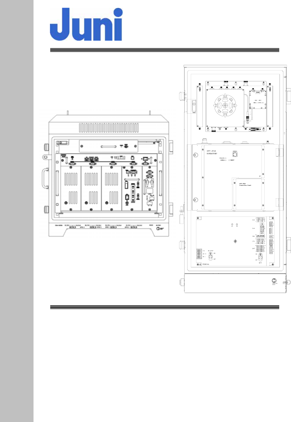
1.4 FFR COMPONENTS ............................................................................................................................... 13
1.5 ADVANTAGES ....................................................................................................................................... 14
1.6 KEY FEATURES ..................................................................................................................................... 15
1.7 GENERAL SAFETY PRECAUTIONS ......................................................................................................... 17
2. SYSTEM DESCRIPTION......................................................................................................................... 19
2.1 FFR SYSTEM ........................................................................................................................................ 19
2.2 SIMULCAST OPERATION........................................................................................................................ 19
2.3 DONOR HUB UNIT ................................................................................................................................ 21
2.3.1 Donor Hub Unit Enclosure and Shelf.............................................................................................. 21
2.3.2 Wireless Modem Antenna ................................................................................................................ 23
2.4 REMOTE UNIT ...................................................................................................................................... 24
2.4.1 Remote Unit..................................................................................................................................... 24
2.4.2 Remote Unit Connectors ................................................................................................................. 26
3. INSTALLATION........................................................................................................................................ 27
3.1 TRANSPORTATION TO THE SITE ............................................................................................................. 27
3.2 HANDLING OF THE REPEATER............................................................................................................... 27
3.3 INSTALLATION CONDITIONS ................................................................................................................. 27
3.4 INSPECTION BEFORE INSTALLING THE REPEATER.................................................................................. 28
3.5 JF-46 FFR INSTALLATION PROCEDURE ................................................................................................ 28
3.5.1 Tools and Materials......................................................................................................................... 28
3.5.2 Cautions during Installation ........................................................................................................... 29
3.5.3 Optical Fiber Jumper Cable Assembly............................................................................................ 29
3.5.4 Weatherproofing Connectors........................................................................................................... 30
3.5.5 Donor Unit Eye Bolts...................................................................................................................... 31
3.5.6 Donor Unit Standard Wall Mount Guide......................................................................................... 32
3.5.7 Remote Unit Eye Bolts..................................................................................................................... 33
3.5.8 Remote Unit Standard Wall Mount Guide....................................................................................... 33
3.5.9 AC Cables and Connectors Installation Guide ............................................................................... 35
3.5.10 Donor Hub Unit Commissioning and Provisioning.................................................................... 36
3.5.11 Remote Unit Commissioning and Provisioning .......................................................................... 38
3.5.12 Operations Tests.......................................................................................................................... 40
3.5.12.1 Optic Cable Loss Test............................................................................................................................. 40
3.5.13 Setup Procedure for DL/UL Path Gain....................................................................................... 41
3.5.13.1 Setup for DL Gain .................................................................................................................................. 44
3.5.13.2 Setup for UL Gain .................................................................................................................................. 45
3.5.13.3 Caution Items ......................................................................................................................................... 45
3.6 REPLACEMENT OF FAULTY UNITS......................................................................................................... 46
3.6.1 Remote/Donor Unit Replacement.................................................................................................... 46
3.6.2 Optical Module Replacement.......................................................................................................... 46
3.7 STORAGE OF THE REPEATER ................................................................................................................. 47
3.8 SAFETY PRECAUTIONS ......................................................................................................................... 47
4. OPERATION.............................................................................................................................................. 48
4.1 INTRODUCTION..................................................................................................................................... 48
4.2 WEB GUI OPERATION .......................................................................................................................... 48

JUNI JF-46-E1900/CFN03
CDMA FIBER FED REPEATER OPERATIONS MANUAL
JUNI AMERICA PROPRIETARY & CONFIDENTIAL
Revision 0.01 Juni America Inc.
4
4.2.1 Introduction..................................................................................................................................... 48
4.2.2 WEB GUI Connection..................................................................................................................... 49
4.2.3 Repeater Log In............................................................................................................................... 52
4.2.4 Default Usernames and Passwords................................................................................................. 52
4.2.5 Initial Window................................................................................................................................. 53
4.2.6 Account Window.............................................................................................................................. 54
4.2.7 Clock Window.................................................................................................................................. 55
4.2.8 Network Window ............................................................................................................................. 56
4.2.9 Control Window............................................................................................................................... 56
4.2.9.1 Donor Control Window .......................................................................................................................... 57
4.2.9.2 OTRU Control Window ......................................................................................................................... 58
4.2.9.3 Remote Control Window........................................................................................................................ 59
4.2.10 Advanced Window....................................................................................................................... 61
4.2.11 Upload Window........................................................................................................................... 62
4.2.12 SNMP History Window ............................................................................................................... 62
4.2.13 Alarm History Window................................................................................................................ 63
4.2.14 Alarm Mask Window................................................................................................................... 63
4.2.15 Reboot Window ........................................................................................................................... 64
4.3 NETWORK MENU.................................................................................................................................. 65
4.3.1 SNMP Configuration....................................................................................................................... 65
4.3.1.1 Introduction............................................................................................................................................ 65
4.3.1.2 Trap Server IP Address Set up................................................................................................................ 66
4.3.1.3 Heartbeat Interval Set up........................................................................................................................ 66
4.3.2 Network Set up ................................................................................................................................ 67
4.3.2.1 Wireless Network Information ............................................................................................................... 67
4.3.2.2 Local Network Information.................................................................................................................... 67
5. SYSTEM MAINTENANCE...................................................................................................................... 69
5.1 PERIODIC MAINTENANCE ..................................................................................................................... 69
5.1.1 Donor Unit Fan Maintenance......................................................................................................... 69
5.1.2 Remote Unit Fan Maintenance........................................................................................................ 70
5.2 FAULT DETECTION AND ALARM REPORTING......................................................................................... 70
5.3 TROUBLESHOOTING FOR THE DONOR UNIT .......................................................................................... 75
5.4 TROUBLESHOOTING FOR THE REMOTE UNIT ........................................................................................ 76
6. TECHNICAL CUSTOMER SUPPORT................................................................................................... 78
APPENDIX A. JF-46 MECHANICAL PACKAGING .................................................................................... 79
1. DONOR UNIT ............................................................................................................................................ 79
2. REMOTE UNIT........................................................................................................................................... 82
APPENDIX B. BLOCK DIAGRAM................................................................................................................. 83
APPENDIX C. BATTERY BACKUP................................................................................................................ 86
APPENDIX D. DONOR HUB UNIT AND REMOTE UNIT ATTENUATION SETTINGS TABLE ......... 88
APPENDIX E. BTS HOTEL RACK INSTALLATION PROCEDURE ........................................................ 89
APPENDIX F. SIMULCAST AND NON-SIMULCAST OPERATIONS ...................................................... 90
APPENDIX G. PRODUCT LISTING AND ITEM MASTER LIST .............................................................. 92

JUNI JF-46-E1900/CFN03
CDMA FIBER FED REPEATER OPERATIONS MANUAL
JUNI AMERICA PROPRIETARY & CONFIDENTIAL
Revision 0.01 Juni America Inc.
5
Table of Figures
[FIGURE 1.1.1] SYSTEM CONFIGURATION...............................................................................................................9
[FIGURE 1.2.1] HANDOFF BETWEEN BTS AND REPEATER.....................................................................................11
[FIGURE 1.4.1] DONOR HUB UNIT ENCLOSURE [FIGURE 1.4.2] REMOTE UNIT .............................................13
[FIGURE 2.1.1] SYSTEM BLOCK DIAGRAM............................................................................................................19
[FIGURE 2.2.1] SIMULCAST BLOCK DIAGRAM ......................................................................................................20
[FIGURE 2.3.1] MAIN COMPONENTS OF THE DONOR HUB UNIT ...........................................................................21
[FIGURE 2.3.2] DONOR HUB UNIT SHELF INTERFACE...........................................................................................22
[FIGURE 2.3.3] DONOR HUB UNIT EXTERNAL CONNECTORS (BOTTOM VIEW).....................................................23
[FIGURE 2.4.1] MAIN COMPONENTS OF THE REMOTE UNIT ..................................................................................24
[FIGURE 2.4.2] REMOTE UNIT EXTERNAL CONNECTORS (BOTTOM VIEW)...........................................................26
[FIGURE 3.5.1] OPTICAL FIBER JUMPER CABLE....................................................................................................30
[FIGURE 3.5.2] CONNECT CABLE TO CONNECTOR .................................................................................................30
[FIGURE 3.5.3] FASTEN CABLE TO CONNECTOR ....................................................................................................30
[FIGURE 3.5.4] WRAP CONNECTION WITH BUTYL TAPE ........................................................................................30
[FIGURE 3.5.5] WRAP OVER BUTYL TAPE WITH ELECTRIC TAPE ............................................................................31
[FIGURE 3.5.6] DONOR UNIT EYE BOLT PATTERNS...............................................................................................31
[FIGURE 3.5.7] DONOR HUB UNIT WALL MOUNTING ...........................................................................................32
[FIGURE 3.5.8] REMOTE UNIT EYE BOLT PATTERN...............................................................................................33
[FIGURE 3.5.9] REMOTE UNIT WALL MOUNTING .................................................................................................34
[FIGURE 3.5.10] STEP 1 ........................................................................................................................................35
[FIGURE 3.5.11] CABLE CONNECTIONS ON THE DHU (FRONT VIEW) ...................................................................37
[FIGURE 3.5.12] CABLE CONNECTIONS ON THE DHU (BOTTOM VIEW)................................................................37
[FIGURE 3.5.13] CABLE CONNECTIONS FOR THE REMOTE UNIT (TOP VIEW) .........................................................39
[FIGURE 3.5.14] CABLE CONNECTIONS FOR THE REMOTE UNIT (BOTTOM VIEW)..................................................39
[FIGURE 3.5.15] CONNECTION TO PERFORM OPTIC CABLE LOSS TEST ...................................................................40
[FIGURE 3.5.16] ONE CARRIER TOTAL OUTPUT POWER OF +45DBM....................................................................42
[FIGURE 3.5.17] TWO CARRIER TOTAL OUTPUT POWER VALUE OF +46DBM........................................................43
[FIGURE 3.5.18] CONNECTION TO SET UP DL GAIN...............................................................................................44
[FIGURE 3.5.19] CONNECTION TO SET UP UL GAIN...............................................................................................45
[FIGURE 4.2.1] OPEN THE CONTROL PANEL..........................................................................................................49
[FIGURE 4.2.2] NETWORK CONNECTIONS.............................................................................................................49
[FIGURE 4.2.3] NETWORK PROPERTIES.................................................................................................................50
[FIGURE 4.2.4] INTERNET PROTOCOL(TCP/IP).....................................................................................................50
[FIGURE 4.2.5] INTERNET PROTOCOL(TCP/IP) PROPERTIES.................................................................................51
[FIGURE 4.2.6] DEFAULT ADDRESS.......................................................................................................................51
[FIGURE 4.2.7] REPEATER GUI LOG IN.................................................................................................................52
[FIGURE 4.2.8] INITIAL WINDOW..........................................................................................................................53
[FIGURE 4.2.9] ACCOUNT WINDOW......................................................................................................................54
[FIGURE 4.2.10] CLOCK WINDOW ........................................................................................................................55
[FIGURE 4.2.11] NETWORK WINDOW ...................................................................................................................56
[FIGURE 4.2.12] DONOR CONTROL WINDOW .......................................................................................................57
[FIGURE 4.2.13] OTRU CONTROL WINDOW ........................................................................................................58
[FIGURE 4.2.14] REMOTE CONTROL WINDOW......................................................................................................59
[FIGURE 4.2.15] ADVANCED WINDOW .................................................................................................................61
[FIGURE 4.2.16] UPLOAD WINDOW......................................................................................................................62
[FIGURE 4.2.17] SNMP HISTORY WINDOW..........................................................................................................62
[FIGURE 4.2.18] ALARM HISTORY WINDOW.........................................................................................................63
[FIGURE 4.2.19] ALARM MASK WINDOW.............................................................................................................63
[FIGURE 4.2.20] REBOOT WINDOW ......................................................................................................................64
[FIGURE 4.3.1] NETWORK MENU..........................................................................................................................65
[FIGURE 4.3.2] SNMP OPERATION OVERVIEW .....................................................................................................66
[FIGURE 4.3.3] TRAP SERVER IP ADDRESS ...........................................................................................................66
[FIGURE 4.3.4] HEARTBEAT INTERVAL..................................................................................................................66
[FIGURE 4.3.5] WIRELESS NETWORK INFORMATION ............................................................................................67

JUNI JF-46-E1900/CFN03
CDMA FIBER FED REPEATER OPERATIONS MANUAL
JUNI AMERICA PROPRIETARY & CONFIDENTIAL
Revision 0.01 Juni America Inc.
6
[FIGURE 4.3.6] LOCAL NETWORK INFORMATION..................................................................................................67
[FIGURE 4.3.7] SNMP OPERATION OVERVIEW .....................................................................................................68
[FIGURE A1.1] DONOR UNIT ................................................................................................................................79
[FIGURE A1.2] DONOR UNIT WALL MOUNTING ...................................................................................................80
[FIGURE A1.3] DONOR UNIT FRONT VIEW ...........................................................................................................80
[FIGURE A1.4] DONOR SHELF AND OPTIC MODULE .............................................................................................81
[FIGURE A2.1] REMOTE UNIT WALL MOUNTING..................................................................................................82
[FIGURE B1.1] SYSTEM BLOCK DIAGRAM............................................................................................................83
[FIGURE B1.2] ONE CARRIER TOTAL OUTPUT POWER OF +45DBM......................................................................84
[FIGURE B1.3] TWO CARRIER TOTAL OUTPUT POWER OF +46DBM.....................................................................85

JUNI JF-46-E1900/CFN03
CDMA FIBER FED REPEATER OPERATIONS MANUAL
JUNI AMERICA PROPRIETARY & CONFIDENTIAL
Revision 0.01 Juni America Inc.
7
List of Acronyms and Abbreviations
The acronyms and abbreviations used in this manual are shown in the following list.
AC Alternating Current
AMP Amplifier
ATT Attenuator/Attenuation
BPF Band Pass Filter
BTS Base Transceiver System
C Centigrade
CDMA Code Division Multiple Access
COM Common
Config Configuration
DC Direct Current
DHU Donor Hub Unit
DL Downlink
DOC Donor Optic Cavity
DRCU Donor Repeater Control Unit
EMS Element Management System
EVDO Evolution Data Only
FFR Fiber Fed Repeater
FRPS Ferro Resonant Power Supply
FSK Frequency Shift Keying
FTP File Transfer Protocol
FWD Forward
IP Internet Protocol
JF-46 Juni Fiber Repeater 46dBm
LD Laser Diode
LED Light Emitting Diode
LMT Local Management Terminal
LNA Low Noise Amplifier
LPA Linear Power Amplifier
MHz Megahertz
OTRU Optic TRansceiver Unit
PA Power Amplifier

JUNI JF-46-E1900/CFN03
CDMA FIBER FED REPEATER OPERATIONS MANUAL
JUNI AMERICA PROPRIETARY & CONFIDENTIAL
Revision 0.01 Juni America Inc.
8
PC Personal Computer
PCS Personal Communications System
PD Photo Diode
PSU Power Supply Unit
REV Reverse
RF Radio Frequency
RRCU Remote Repeater Control Unit
RU Remote Unit
Rx Receive
SAW Surface Acoustic Wave
SNMP Simple Network Management Protocol
TDR Time Domain Reflectometer
Tx Transmit
UL Uplink
USB Universal Serial Bus
VAC Voltage Alternating Current
VDC Voltage Direct Current
VSWR Voltage Standing Wave Ratio
WDM Wavelength Division Multiplexer
JUNI JF-46-E1900/CFN03
CDMA FIBER FED REPEATER OPERATIONS MANUAL
JUNI AMERICA PROPRIETARY & CONFIDENTIAL
Revision 0.01 Juni America Inc.
9
1. Introduction
1.1 Fiber Fed Repeater
The JF-46 FFR provides a cost effective solution for cell coverage extension and
increased call quality in shadow areas. It is a RF signal transport system that
provides long range RF coverage where it is impractical to install a BTS.
The JF-46 FFR is designed to be strategically placed to overcome difficult zoning
issues by allowing the base stations to remain at a central location while placing
antennas at remote locations. RF signals can be transported to remote locations to
expand coverage into areas not receiving service or to extend coverage into difficult
to reach areas such as canyons, tunnels and underground parking lots and roadways.
The JF-46 FFR provides a high-tech, highly-efficient service system which enables
high quality communication at low cost, due to the system’s utilization of one optical
fiber core between the DHU and RU supporting full duplex transmission of signals for
both the DL and UL.
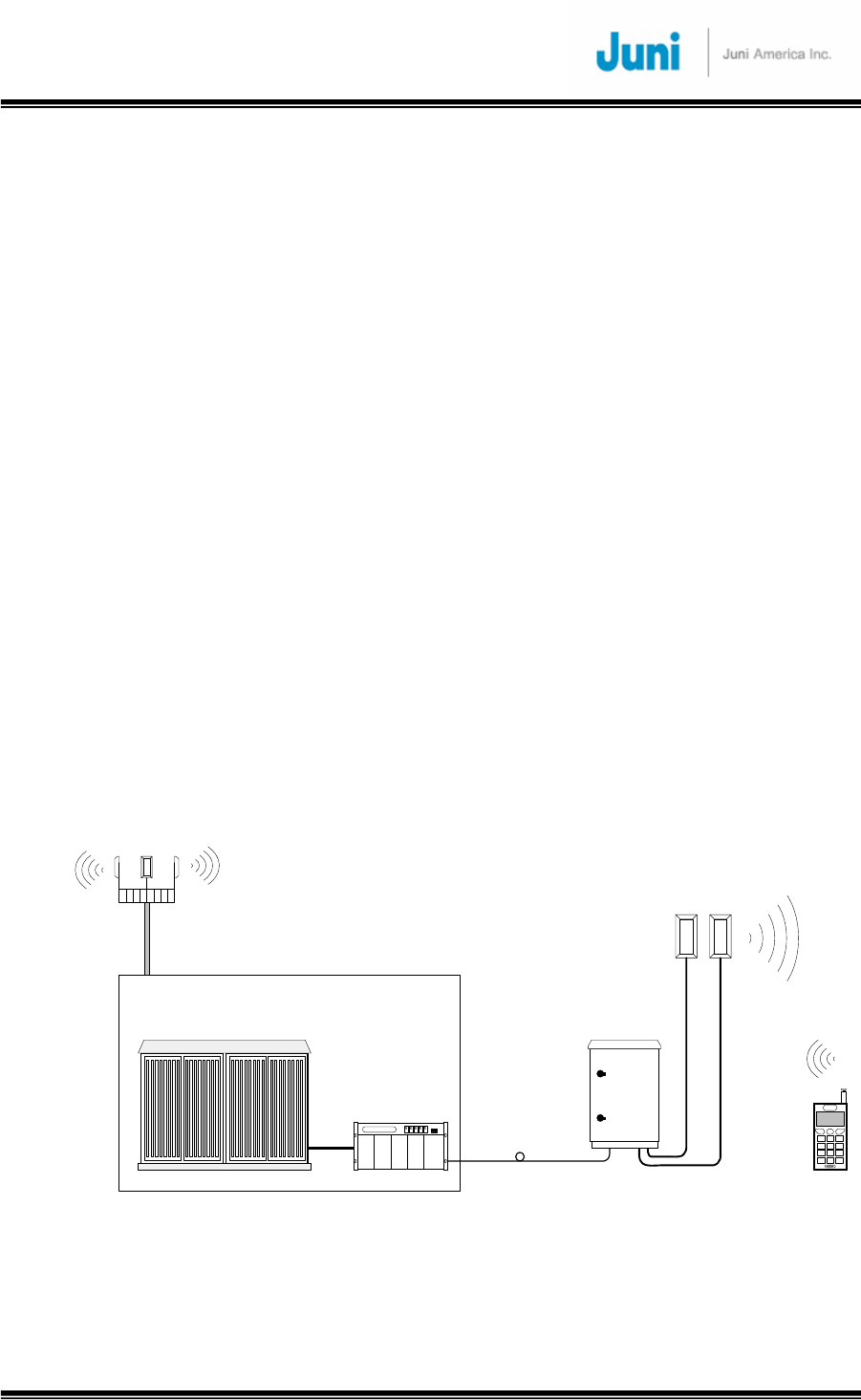
Base Station
BTS
Donor
Remote
DL/UL_0
Ant.
UL_1
Ant.
Optic Link
[FIGURE 1.1.1] SYSTEM CONFIGURATION

JUNI JF-46-E1900/CFN03
CDMA FIBER FED REPEATER OPERATIONS MANUAL
JUNI AMERICA PROPRIETARY & CONFIDENTIAL
Revision 0.01 Juni America Inc.
10
1.2 Search Window
The purpose of using a repeater is to extend the coverage of the BTS by re-
transmitting the BTS signals to mobile stations in a non BTS coverage area. This
means that the BTS handles all kinds of call processing including calls being received
via the repeater. There may be a negative impact of service on the BTS if the
interface between BTS and repeater does not operate properly.
There would be an increase in time delay with calls received from the repeater,
compared to a call from its BTS coverage. Thus the additional delay introduced from
calls via the repeater must be considered while setting BTS parameters.
Window-size is the time range of the BTS traffic channel to search for the signal
originating from the MS. If the delayed signal is out of window-size, the BTS cannot
acquire the signal, which will result in dropped calls due to chip-delay.
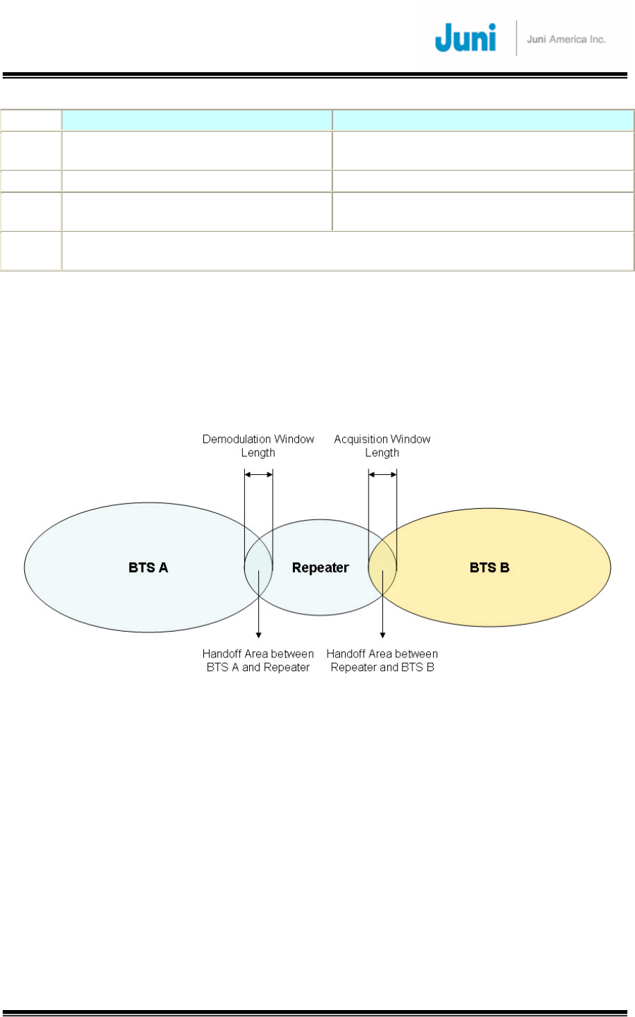
Table 1.2.1 describes the two parameters used for controlling the window length, to
prevent the deterioration of call quality caused by chip delay. It is required to search
the signal properly by adjusting the two parameters.
Acquisitioin_Window_Length is adjusted to change the window size used to
search/monitor the neighboring PN and allow soft handoff while traveling to the
neighboring BTS where new traffic channels will be allocated to the MS.
Demodulation_Window_Length is adjusted to change the window size which searches
for the Rx signals. This parameter should be adjusted when the delay (with no change
of traffic channel) between transmission and reception is increased i.e. MS in repeater
service area.
JUNI JF-46-E1900/CFN03
CDMA FIBER FED REPEATER OPERATIONS MANUAL
JUNI AMERICA PROPRIETARY & CONFIDENTIAL
Revision 0.01 Juni America Inc.
11
Acquisition_Window_Length Demodulation_Window_Length
Purpose Window Range of BTS traffic channel
to search for time sync of other BTS
Window Range of BTS traffic channel to
search multi path referring to the time-offset
Unit 1/8 chip/unit 1/8 chip/unit
Remark Use this parameter when traffic
channel is changed (Soft hand off)
Use this parameter when traffic channel is
not changed. (Tracking multi path signal)
Notice Too big a Window_size causes increase of time for the mobiles to search for BTS
signal. It should be set up with proper values considering time delay.
[Table1.2.1] Two Parameters for Search Window Setup
Therefore, the two parameters stated can be used to adjust the interface between
the BTS and the repeater considering the movement of the MS. Picture 1 shows an
example of two window size parameters for the JF-46 repeater application.
[FIGURE 1.2.1] HANDOFF BETWEEN BTS AND REPEATER
The Demodulation_Window_Length is used to adjust the time sync to compensate
the chip delay introduced by the optic core when the MS moves into the repeater
coverage area.
When the MS travels from the repeater coverage to the BTS B area,
Acquisition_Window_Length is used to adjust this time offset differences. With this
adjustment, the MS will be able to perform soft handoff from BTS A traffic channel
(while in repeater coverage) to the BTS B traffic channel.
Without these adjustments, there may have been two call drops while the MS traveled
from BTS A to BTS B.

JUNI JF-46-E1900/CFN03
CDMA FIBER FED REPEATER OPERATIONS MANUAL
JUNI AMERICA PROPRIETARY & CONFIDENTIAL
Revision 0.01 Juni America Inc.
12
1.3 Total Optical Delay (Window Size)
With the adjustments described above, good call quality should be maintained without
call drops. This section will show how to calculate the total delay and how the
parameters should be set up in the BTS. The equation below is an example of total
delay for an optic repeater.
SD(μsec) + OD(km) + RD(μsec) + RR(km)
SD : BTS System Delay (Time delay between antenna input port and demodulator in BTS)
OD : Optic Distance between BTS and repeater.
RD : Repeater System Delay
RR : Repeater Coverage Radius
* 1 chip = around 244 m
The total chip delay of 2km of RR and 5km of OD is as below.
36chip + 5000m(20.63chip) + 5 μ sec(6.6chip) + 2000m(8.25chip) = 71.45 chips (Approx.
72chips)
Based on the calculation of total chip delay, the two parameters should be adjusted for
good call quality when installing a new repeater. 71.45 chip delay corresponds to 12
(set value) Search window size (Size = 160 chips). Therefore, the
demodulation_window_length of BTS A should be set up as 12 in this configuration
and acquisition_window_length of BTS A and BTS B should also be set up as 12.
The table below shows the Search window size values for different optic distances
and repeater coverage.
OD + RR Search Window Size
km chip
SD + RD
(Chips)
Sum
(Chips)
2 x Sum
(Chips) Set Value Size (Chips)
1 4.13 42.6 46.73 93.45 11 114
2 8.25 42.6 50.85 101.70
12 160
3 12.38 42.6 54.98 109.95 12 160
4 16.50 42.6 59.10 118.20 12 160
5 20.63 42.6 63.23 126.45 12 160
6 24.75 42.6 67.35 134.70 12 160
7 28.88 42.6 71.48 142.95 12 160
8 33.00 42.6 75.60 151.20 13 226
JUNI JF-46-E1900/CFN03
CDMA FIBER FED REPEATER OPERATIONS MANUAL
JUNI AMERICA PROPRIETARY & CONFIDENTIAL
Revision 0.01 Juni America Inc.
13
9 37.13 42.6 79.73 159.45 13 226
10 41.25 42.6 83.85 167.70 13 226
11 45.38 42.6 87.98 175.95 13 226
12 49.50 42.6 92.10 184.20 13 226
13 53.63 42.6 96.23 192.45 13 226
14 57.75 42.6 100.35 200.70 13 226
15 61.88 42.6 104.48 208.95 13 226
16 66.00 42.6 108.60 217.20 14 320
17 70.13 42.6 112.73 225.45 14 320
18 74.25 42.6 116.85 233.70 14 320
19 78.38 42.6 120.98 241.95 14 320
20 82.50 42.6 125.10 250.20 14 320
21 86.63 42.6 129.23 258.45 14 320
22 90.75 42.6 133.35 266.70 14 320
23 94.88 42.6 137.48 274.95 14 320
24 99.00 42.6 141.60 283.20 14 320
25 103.13 42.6 145.73 291.45 14 320
26 107.25 42.6 149.85 299.70 14 320
27 111.38 42.6 153.98 307.95 14 320
28 115.50 42.6 158.10 316.20 15 452
29 119.63 42.6 162.23 324.45 15 452
30 123.75 42.6 166.35 332.70 15 452
[Table1.3.1] Example Table for Search Window Size
1.4 FFR Components
The JF-46 FFR system comprises of two main elements, a DHU and RU.
[FIGURE 1.4.1] DONOR HUB UNIT ENCLOSURE [FIGURE 1.4.2] REMOTE UNIT

JUNI JF-46-E1900/CFN03
CDMA FIBER FED REPEATER OPERATIONS MANUAL
JUNI AMERICA PROPRIETARY & CONFIDENTIAL
Revision 0.01 Juni America Inc.
14
The DHU Enclosure includes the following:
• Donor Optic Module
• Donor Tx/Rx (FSK Modem included) Module
• Control Module
• Wireless Modem
• Power Supply.
Donor Hub Unit transforms the RF signals from the BTS into optic signals, and then the
optic signals are transmitted to Remote Unit.
Donor Hub Unit also transforms the optic signals from Remote Unit into RF signals, and
then the RF signals are transmitted to the BTS.
The RU includes the following:
• Remote Optic Module
• Control Module
• LPA
• LNA
• Cavity BPF
• Power Supply
Remote Unit transforms the optic signals from the Donor Hub Unit into RF signals, and
then the RF signals are transmitted to Antenna.
Remote Unit also transforms the RF signals from Antenna into optic signals, and then the
optic signals are transmitted to the Donor Hub Unit.
1.5 Advantages
There are many advantages to deploying a FFR.
• Supports adjacent block interference protection which allows just one model of the
FFR to cover the entire PCS frequency range.(Changing the Cavity BPF) The FFR
is settable to allow a combination of 94 different frequencies to be serviced. This
advanced filtering personality prevents interference from adjacent frequency
blocks.
• Allows for versatile deployment architectures. Extra optical transceiver modules

JUNI JF-46-E1900/CFN03
CDMA FIBER FED REPEATER OPERATIONS MANUAL
JUNI AMERICA PROPRIETARY & CONFIDENTIAL
Revision 0.01 Juni America Inc.
15
can be added to the DHU to increase service coverage. A flexible RF splitter unit
can also be implemented to combine multiple RF ports supported by newer BTS.
• The slim and sleek appearance of the RU allows it to be installed and deployed in
difficult zoning areas.
• The water and moisture resistant IP55-rated design make it reliable and durable.
• The FFR system is monitored and controlled from a central remote location by
making use of a CDMA wireless modem via the SNMP protocol.
• Operation, maintenance and repairs are simple. The system provides alarms and
information on the repeater gain settings, output level control, LPA on/off, internal
temperature monitoring and problems concerning the optic module. The system is
designed to operate with a comprehensive network management system.
• The system uses only one optical fiber core for transmission and reception of
signals. To achieve this, WDM is implemented which enables multiple wave-
lengths (DL: 1510nm, UL0: 1530nm, UL1: 1570nm) to be simultaneously
transmitted and received through the one optical fiber core.
1.6 Key Features
• Uses only 1 optical fiber core for DL, UL0 and UL1
• 1xEV-DO and 1xEV-DO Rev. A are supported
• 40 watts composite RF output
• Rx diversity is standard and provides up to 2~8dBo reverse link benefit
• Provides lower life cycle costs by:
9 Reducing fiber lease costs per core
9 Reducing the number of optic cables required for new installations

JUNI JF-46-E1900/CFN03
CDMA FIBER FED REPEATER OPERATIONS MANUAL
JUNI AMERICA PROPRIETARY & CONFIDENTIAL
Revision 0.01 Juni America Inc.
16
• Most responsive and highly innovative product features
9 Remote unit’s standard powering is 115-230 VAC(Free voltage)
9 Multiple mounting options including; wall, pole and floor/pedestal.
• Supports simulcasting of up to 4 RU per sector with one DHU
9 Reduced pilot pollution, better call quality, reduced soft handoff
9 Better network efficiency and equipment utilization
9 Existing base station equipment could be deployed elsewhere
9 Donor RF Combiner is compatible with newer base station having multiple DL
output RF ports and provides Future-Proof BTS interface
SECTION SPEC OTHERS
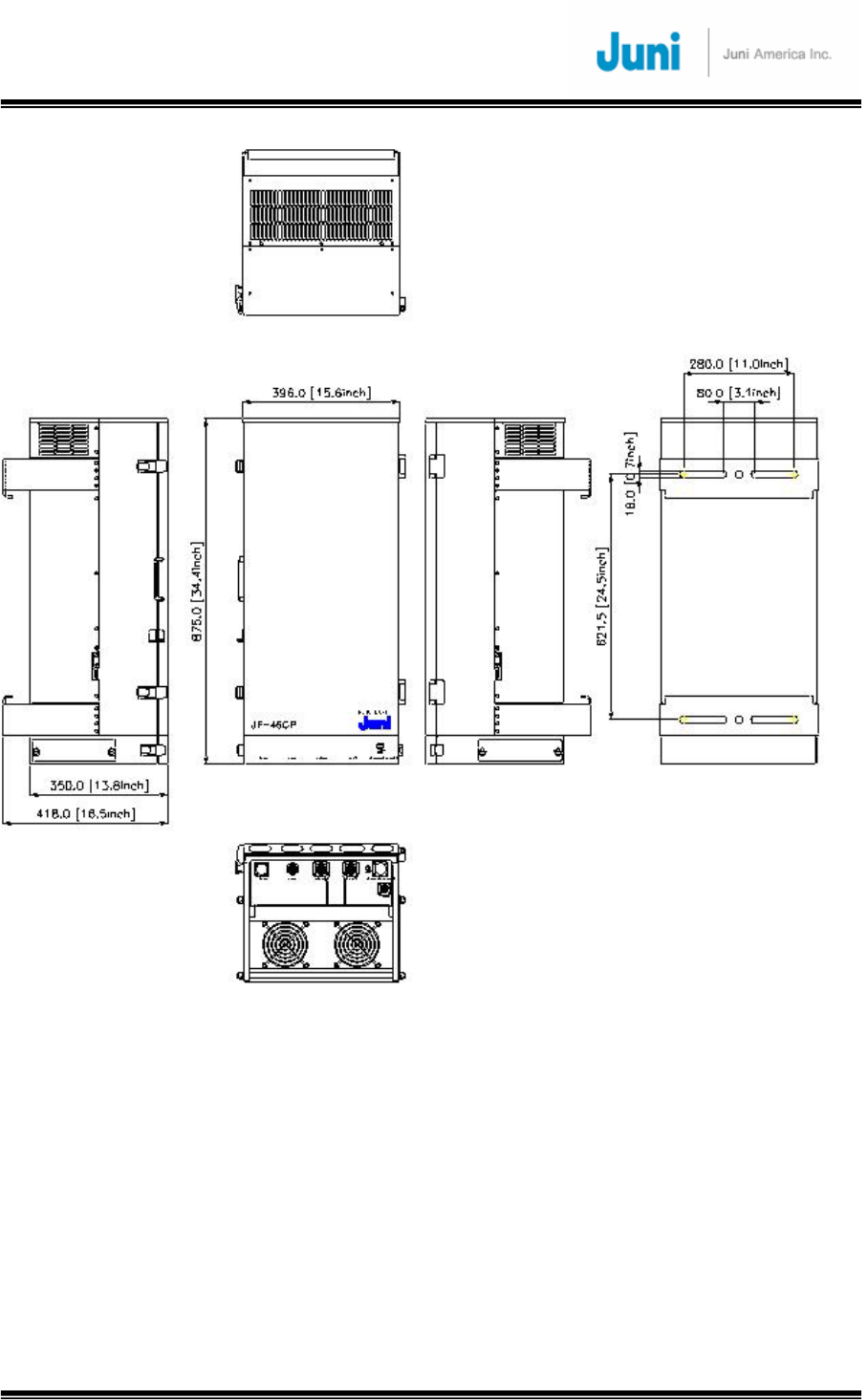
Donor shelf size 482.6*266*400mm3(W*H*D) Donor self
Enclosure size 538*545*615.5mm3(W*H*D) Enclosure
Remote Weight <= 180 lbs Remote Weight
Remote Size 396*875*418mm3(W*H*D) Remote Size
Arrester Lightning Protection on all RF
Interface connectors
Arrester
Remote RF Connector 7/16 DIN Female connectors Remote RF Connector
Donor RF Connector Donor shelf: SMA Female
Enclosure: N Female
Donor RF Connector
MS3102A18-21P (3pin male) Remote AC
115-230 VAC(Free voltage)
MS3102A18-21P (3pin male) Donor AC
115-230 VAC(Free voltage)
Power
Connector
MS3102E20-23P (2pin male) Battery
(Charging Current : 2A_max)
JUNI JF-46-E1900/CFN03
CDMA FIBER FED REPEATER OPERATIONS MANUAL
JUNI AMERICA PROPRIETARY & CONFIDENTIAL
Revision 0.01 Juni America Inc.
17
1.7 General Safety Precautions
This equipment contains components that emit laser radiation which can
seriously damage the retina of the eye. Do not look into the ends of any
optical fiber. Do not look directly into the optical transceiver of any digital unit
or exposure to laser radiation may result. An optical power meter or
reflectometer should be used to verify active fibers. Place a protective cap or
lid immediately over any radiating transceiver or optical fiber connector to
avoid potential damage caused by radiation exposure. This practice also
prevents dirt particles entering the openings.
The optical fiber emits radiation. Do not look directly into the ends of an
optical fiber. This may result in exposure to radiation. Do not assume laser
power is turned off or the fiber is disconnected at the other end.
Wet locations and conditions will increase the risk of electrical shock when
installing or using electrical powered equipment. To prevent electrical shock,
never install or use electrical equipment in wet locations or during lightning
storms.
The DHU is powered by 115-230 VAC. To prevent electrical shock when
installing or maintaining the DHU, disconnect the wiring at the power source
before working with un-insulated wires or terminals.
The RU is typically powered by 115-230 VAC. To prevent electrical shock
when installing or maintaining the RU, disconnect the wiring at the power
source before working with un-insulated wires or terminals.
Always consider and allow sufficient fiber length to permit routing or patch
cords and pigtails without severe bends. Fiber optic patch cords or pigtails
may be permanently damaged if bent or curved to a radius of less than 2
inches (50mm).
JUNI JF-46-E1900/CFN03
CDMA FIBER FED REPEATER OPERATIONS MANUAL
JUNI AMERICA PROPRIETARY & CONFIDENTIAL
Revision 0.01 Juni America Inc.
18
Static electricity means no risk of personal injury but it can severly damage
and corrupt essential circuitry within the equipment, if not handled carefully.
Parts on the printed circuit boards as well as other parts in the equipment are
sensitive to electrostatic discharge.
Never touch the printed circuit boards or uninsulated conductor surfaces
unless absolutely necessary.
If the printed circuit boards must be handled, always use ESD protective
devices or first touch the enclosure with your hand and then do not move
your feet.
This equipment is only intended to be installed by professionally qualified
and trained personnel.
Risk of explosion if battery is replaced by an incorrect type. Dispose of used
batteries according to the instructions.
JUNI JF-46-E1900/CFN03
CDMA FIBER FED REPEATER OPERATIONS MANUAL
JUNI AMERICA PROPRIETARY & CONFIDENTIAL
Revision 0.01 Juni America Inc.
19
2. System Description
2.1 FFR System
The JF-46 FFR is made up of a main Donor Hub Unit (DHU) and a RU. The DHU and
RU are divided into modules to allow easy operation and maintenance. It can operate
even in the harshest environmental conditions due to its durable IP55-rated
weatherproof enclosure.
[FIGURE 2.1.1] SYSTEM BLOCK DIAGRAM
2.2 Simulcast Operation
Please refer to Figure 2.2.1 for a system block diagram of a Simulcast FFR
configuration, where a single BTS sector provides coverage to two Remote Units. This
configuration employs two RF Splitter/Combiner units at the RF ports of the Donor
Hub Unit which relate to the two Remote Units.
On the DL path, the BTS signal is split two ways and feeds two DHU input ports.
Similarly, on the UL path, the signals from two DHU RF ports are summed and fed to
one port of the BTS.
JUNI JF-46-E1900/CFN03
CDMA FIBER FED REPEATER OPERATIONS MANUAL
JUNI AMERICA PROPRIETARY & CONFIDENTIAL
Revision 0.01 Juni America Inc.
20
The JF-46 FFR has adequate RF gain margin to support a Splitter/Combiner as
shown with loss of up to 10 dB. As a result, a single BTS sector can easily feed 4 or
even 8 Remote Units. If more than 4 Remote Units are to be supported, more than
one DHU is required since a DHU can support only a maximum of 4 Optic Modules,
which drive 4 Remote Units.
[FIGURE 2.2.1] SIMULCAST BLOCK DIAGRAM
JUNI JF-46-E1900/CFN03
CDMA FIBER FED REPEATER OPERATIONS MANUAL
JUNI AMERICA PROPRIETARY & CONFIDENTIAL
Revision 0.01 Juni America Inc.
21
2.3 Donor Hub Unit
This section describes the main components of the DHU, the functions performed by
the components and the user interface.
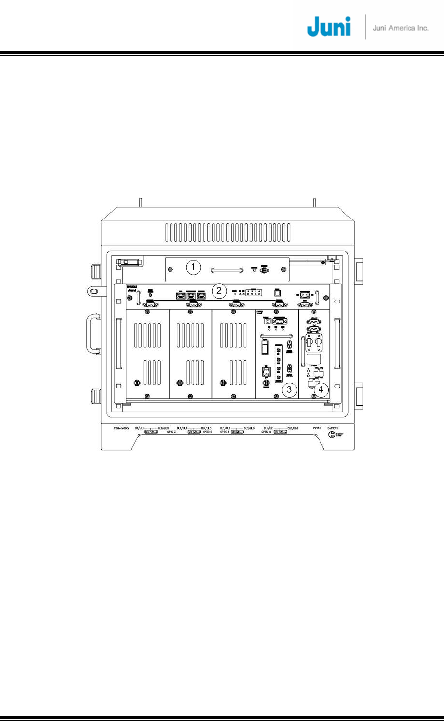
2.3.1 Donor Hub Unit Enclosure and Shelf
[FIGURE 2.3.1] MAIN COMPONENTS OF THE DONOR HUB UNIT
① FAN: Provides ventilation and disperses heat evenly.
② DRCU (Donor Repeater Control Unit): Monitors and controls each internal
module. Also monitors and controls the RU by data communication. Monitoring
the control and status of all repeaters can only be managed at an
administrative level via the internal SNMP agent.
③ OTRU(Optic Transceiver Unit): Converts the RF signal (from the BTS) into an
optical signal and transmits the signal to the RU. Conversely, the RU converts
the optic signal and transmits it to the BTS.
④ PSU (Power Supply Unit): Converts the input power AC power (115-230VAC, free
voltage) into DC+27V, DC+15V, DC +7V and supplies the power to the modules.
JUNI JF-46-E1900/CFN03
CDMA FIBER FED REPEATER OPERATIONS MANUAL
JUNI AMERICA PROPRIETARY & CONFIDENTIAL
Revision 0.01 Juni America Inc.
22
[FIGURE 2.3.2] DONOR HUB UNIT SHELF INTERFACE
① CDMA Modem RF Port (Female SMA-Type): An RF cable connects the CDMA
wireless modem port on the DRCU to the modem RF port situated on the
outside of the enclosure in case of outdoor type.
② Debug and Ethernet port: Ethernet port to allow connection to any PC for
debugging via the GUI, allow connection to IP Control Box for SNMP
③ DRCU and SNMP reset Key and LEDs: Hard reset button to restart the DRCU and
SNMP agent. LEDs to display the status of the System.
④ DRCU Power switch: Turns the power on/off for the DRCU only.
⑤ Main and battery power switch: Main power switch located on the power supply
which provides power to the entire DHU.
⑥ RF in/out port (Female SMA): RF ports on a single optic transceiver supports
only one sector. This port is connected to the enclosure with RF cables.
⑦ Monitoring port (Female SMA): Ports used to monitor signals existing within the
DHU with a spectrum analyzer or test equipment.
⑧ OTRU Power switch: Turns the power on/off for the OTRU only.
⑨ Optic connector : Connector to where the fiber is connected to.
JUNI JF-46-E1900/CFN03
CDMA FIBER FED REPEATER OPERATIONS MANUAL
JUNI AMERICA PROPRIETARY & CONFIDENTIAL
Revision 0.01 Juni America Inc.
23
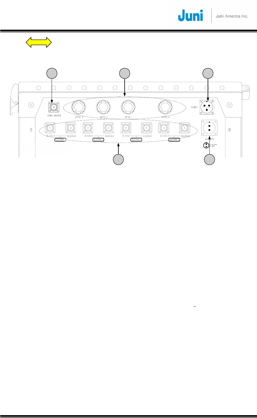
⑩
1 2 3
4 4
[FIGURE 2.3.3] DONOR HUB UNIT EXTERNAL CONNECTORS (BOTTOM VIEW)
① CDMA modem RF port (Female N-Type): External Antenna for modem connected
to this port.
② Fiber Entrance: The fiber is passed through to connect to the optic transceiver.
③ AC power connector (Female weatherproof MS type): Connectors used for AC
powering. The AC power cable is supplied by the manufacturer.
④ RF in/out port (Female N type): Provides connection to the BTS.
⑤ Battery connector (Female weatherproof MS type): Connector for backup battery
unit.
2.3.2 Wireless Modem Antenna
The technical requirements for the Wireless Modem Antenna are dependent on the
specific DHU location and network coverage. If the nearest BTS with a local antenna
is nearby the DHU, a 3 dBi Gain Omni antenna should be quite adequate. The
Modem Antenna is to be connected to the modem antenna connector on the DHU.
In the event the nearest BTS with a local antenna is quite some distance from the
DHU, a directional antenna with 10 dBi Gain, aimed at the nearest BTS with the local
antenna, is the appropriate modem antenna solution.
: Data and power cable
JUNI JF-46-E1900/CFN03
CDMA FIBER FED REPEATER OPERATIONS MANUAL
JUNI AMERICA PROPRIETARY & CONFIDENTIAL
Revision 0.01 Juni America Inc.
24
2.4 Remote Unit
This section describes the main components of the RU, the functions performed by
the components and the user interface.
2.4.1 Remote Unit
OPTIC
AC_IN UL_1
DL/UL_0 BATTERY (Max 0.7A)
NMS
350_IN UL0_IN
NMS DL_OUTUL1_IN 320 _OUT
SPT-JF46
Remote_Optic Module
3
1 2
344
5
6
7
8 8
[FIGURE 2.4.1] MAIN COMPONENTS OF THE REMOTE UNIT
① Remote Optic Module: Converts the optic signal (from DHU) into RF signal.
Conversely, it converts the RF signal (from the RU) into an optic signal.
② Duplexer & BPF: Filters out the unwanted signals on the FWD and REV path.
③ FSK Modem: Modem for communications between the DHU and the RU.
④ Low Noise Amplifier (LNA): Performs low noise amplification on received signals.

JUNI JF-46-E1900/CFN03
CDMA FIBER FED REPEATER OPERATIONS MANUAL
JUNI AMERICA PROPRIETARY & CONFIDENTIAL
Revision 0.01 Juni America Inc.
25
⑤ LPA (Linear Power Amplifier): A 60 Watt 6 carrier amplifier which amplifies the
signal into high output power for transmitting to the DL antenna. The amplifier is
operated by +30VDC and has a 43dB Gain.
⑥ Control Module: Used to monitor and control the RU. Also manages the
communication with the DHU.
⑦ Power Supply: Converts the input power (115-230VAC, free voltage) into DC+30V,
DC +7V and supplies this power to the modules. Also, turns the FAN On/Off by
detecting the internal temperature of the unit and alerting the Control module (⑥)
the current status of the FAN .
⑧ Arrestor: Protects the system against lightning surges. No external lightning
arrestors are required.
JUNI JF-46-E1900/CFN03
CDMA FIBER FED REPEATER OPERATIONS MANUAL
JUNI AMERICA PROPRIETARY & CONFIDENTIAL
Revision 0.01 Juni America Inc.
26
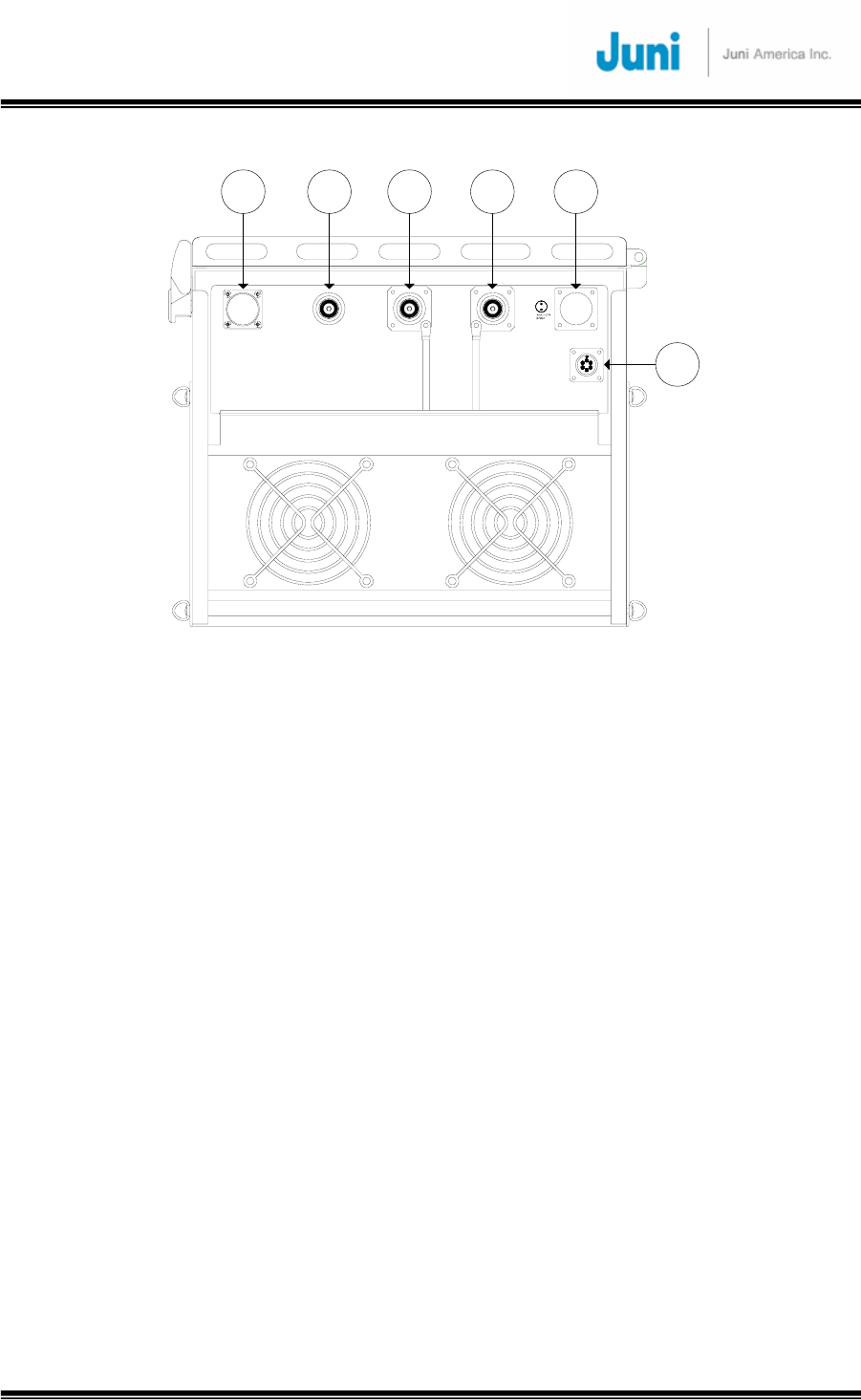
2.4.2 Remote Unit Connectors
1
BATTERY(Max 0.7A)
OPTIC
AC_IN DL/UL_0 UL_1
FAN
A
B
D
C
E
F
2 3 4 5
6
[FIGURE 2.4.2] REMOTE UNIT EXTERNAL CONNECTORS (BOTTOM VIEW)
① AC power connector: Male AC power connector to allow connection for a female
MS3102 Type AC power connector and AC power feeder cable.
② Fiber entrance port: A non metallic liquid tight strain relief is connected to the port
with a fiber core fed through the center into the RU.
③ DL/UL0 path in/out port: Female DIN type DL/UL path port making use of a single
fiber core for full duplex operation. An antenna is connected to this port to transmit
and receive signals.
④ UL1 path input port: Female DIN type Diversity uplink/receive path port to connect
a second antenna
⑤ Battery connector: A weatherproof two pin MS connector used to connect an
external battery backup unit.
⑥ FAN connector: A weatherproof six pin MS connector used to connect the fan unit.

JUNI JF-46-E1900/CFN03
CDMA FIBER FED REPEATER OPERATIONS MANUAL
JUNI AMERICA PROPRIETARY & CONFIDENTIAL
Revision 0.01 Juni America Inc.
27
3. Installation
3.1 Transportation to the Site
During transportation of the repeater to the site, the following points need to be
considered.
• While transporting the repeater unit, it is advised to pack the repeater in its
original packaging supplied by Juni America.
• It is important to prevent any shock applied to the repeater units while
loading/unloading to/from the vehicle.
• During transportation, it is advised to prevent or minimize any movement of the
packed repeater units.
3.2 Handling of the Repeater
The user should prevent any defect caused by an accident, misuse, abuse, insect
infestations, “Acts of God”, improper installation or operation, lack of reasonable care,
unauthorized modification, and loss of parts, tampering or any repair by a person not
authorized by Juni America. As the JF-46 repeater is heavy equipment, the installer
should be careful and seek assistance while attempting to lift/carry/move the units.
3.3 Installation Conditions
• Avoid direct sunlight and place the repeater in a well ventilated location.
• The environment temperature should be in a range of –20°C to +55°C.
• Ground connections should be made to all metal cabinets for safety.
• Avoid any vibration.
• The VSWR of the cable which connects the repeater to the antenna should be less
than 1:1.5

JUNI JF-46-E1900/CFN03
CDMA FIBER FED REPEATER OPERATIONS MANUAL
JUNI AMERICA PROPRIETARY & CONFIDENTIAL
Revision 0.01 Juni America Inc.
28
3.4 Inspection before Installing the Repeater
• Check for any physical damage on the repeater cabinet. If any damage is found, it is
advised to perform close inspection on the operating features and RF signal test to
verify repeater performance.
• Check for loose RF cables inside the repeater.
• Check whether any part of the cabinet is exposed to water or other liquid substances.
• Before installing the repeater, check the serial number of the units to be installed.
• Check all required accessories are available.
3.5 JF-46 FFR Installation Procedure
3.5.1 Tools and Materials
The following tools and materials are required in order to complete the procedures in
the installation process. The installation processes include RF testing and mechanical
installation.
Test equipment required for commissioning by the customer
• RF signal generator
• Portable RF Spectrum analyzer or RF power meter
• RF adaptors
• AC/DC voltmeter
• External attenuators (high power and low power)
• MS3102A18-21S Female power feeder connector
• RF test cables
• 99% pure alcohol wipes
• PC with Internet Explorer software installed
• Optical TDR (Time Domain Reflectometer)
• Butyl tape (rubber tape)
• Electric tape
• RJ-45 Ethernet interface cable
• Various tools such as screwdrivers, spanners etc
• Wireless terminal
• Pencil or pen
• Writing pad

JUNI JF-46-E1900/CFN03
CDMA FIBER FED REPEATER OPERATIONS MANUAL
JUNI AMERICA PROPRIETARY & CONFIDENTIAL
Revision 0.01 Juni America Inc.
29
3.5.2 Cautions during Installation
Caution when connecting the optic cable:
● Clean the connection part of connector using an industrial tissue and 99.9%
pure alcohol.
● After connecting the optic jumper cable, the residual section should be set in
a large circular form to prevent it from folding.
Caution when setting the repeater:
● Do not power on the system while the output port of the system is not
connected.
● Before connecting the DHU input from the BTS, measure and confirm the
DHU input level is within the DHU input dynamic range.
● Confirm the connections of the cables and connectors are tight.
● Confirm the ground connection complies with the safety specifications for
protection against thunderstorms.
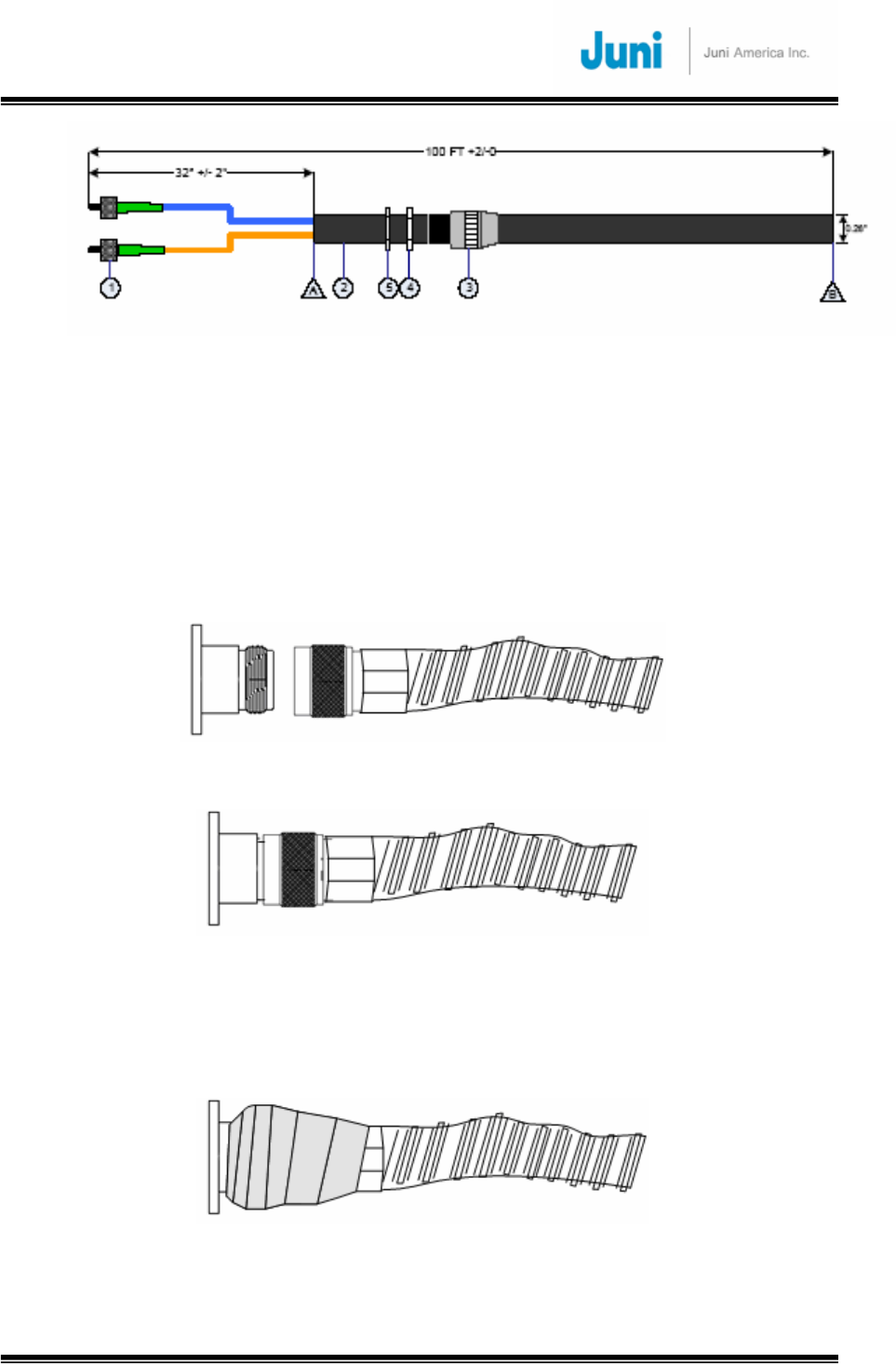
3.5.3 Optical Fiber Jumper Cable Assembly
An Optical Fiber Jumper Cable assembly is available from Juni America, Inc. to
facilitate connection from a single-mode optical fiber transmission facility (dark fiber)
to the DHU or RU. The Optical Fiber Jumper Cable assembly is shown in the figure
below. It has an overall length of approximately 100 feet. It includes a weatherproof
“boot” assembly which serves to seal the circular opening (in the DHU or RU), where
the optical fiber jumper cable enters and connects to the FFR subsystem, via the
FC/APC connector provided.
Only one optical fiber core is required for the optical fiber connection between the
DHU and RU, and a second optical fiber core is provided within the jumper cable
assembly as a “spare”. Should one of the fiber cores fail, ensure the system is turned
off by following the “Replacement of faulty units” section. Unplug the problematic fiber
core from the DHU and RU and plug the spare jumper cable into the unit. This will
only work provided the spare fiber is functioning.
JUNI JF-46-E1900/CFN03
CDMA FIBER FED REPEATER OPERATIONS MANUAL
JUNI AMERICA PROPRIETARY & CONFIDENTIAL
Revision 0.01 Juni America Inc.
30
[FIGURE 3.5.1] OPTICAL FIBER JUMPER CABLE
3.5.4 Weatherproofing Connectors
Once all connectors and cables have been configured and assembled,
weatherproofing is vital to prevent corrosion due to water ingress which could lead to
eventual failure.
1. Making sure that the connector surfaces are clear of residue and dry, firmly
tighten the connectors.
[FIGURE 3.5.2] CONNECT CABLE TO CONNECTOR
[FIGURE 3.5.3] FASTEN CABLE TO CONNECTOR
2. Seal the connector assembly by tightly wrapping Butyl tape over the connection.
Two or more layers should be used so that the tape seals the entire connection
and extends beyond the connector by about an inch.
[FIGURE 3.5.4] WRAP CONNECTION WITH BUTYL TAPE
JUNI JF-46-E1900/CFN03
CDMA FIBER FED REPEATER OPERATIONS MANUAL
JUNI AMERICA PROPRIETARY & CONFIDENTIAL
Revision 0.01 Juni America Inc.
31
3. Tightly wrap electrical tape around the existing Butyl tape making sure to also
extend one inch beyond the Butyl tape to completely envelop the tape and
connector.
[FIGURE 3.5.5] WRAP OVER BUTYL TAPE WITH ELECTRIC TAPE
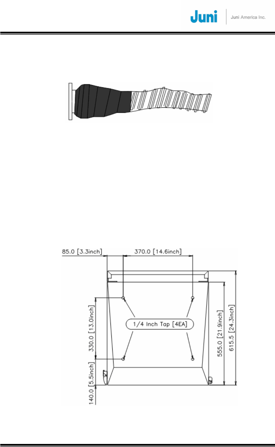
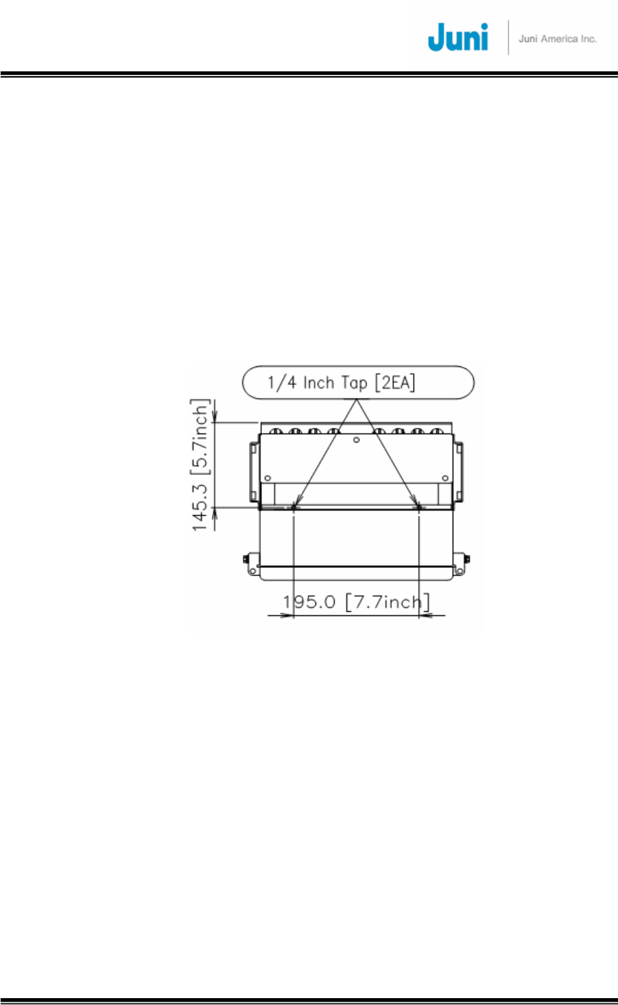
3.5.5 Donor Unit Eye Bolts
There are four eye bolt tapped holes located at the top of the DHU as shown below.
The length of the tapped hole is 0.97 inches or 25mm. The customer supplied ¼”
20UNC eye bolts may be used to assist in hoisting the DHU above the ground for wall
or pole mount solutions.
Ensure that the eyebolts are securely attached to the top of the DHU. Check that the
cables used to lift the DHU is securely fastened to the eyebolts before it is lifted.
[FIGURE 3.5.6] DONOR UNIT EYE BOLT PATTERNS
JUNI JF-46-E1900/CFN03
CDMA FIBER FED REPEATER OPERATIONS MANUAL
JUNI AMERICA PROPRIETARY & CONFIDENTIAL
Revision 0.01 Juni America Inc.
32
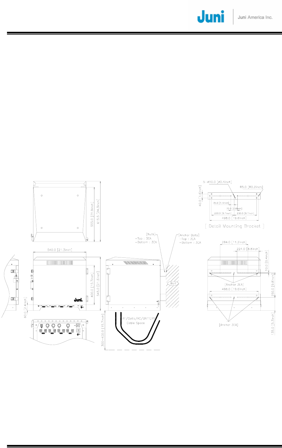
3.5.6 Donor Unit Standard Wall Mount Guide
The DHU is capable of being wall mounted. There are two horizontal panels
protruding slightly behind the DHU, with holes along the panel to allow bolts and nuts
to be fastened. The wall mount holes will accommodate bolt diameters up to a
maximum of 0.4 inches. Drill holes in the wall or area in which it is to be installed to
match the mounting holes on the panels.
Attach the DHU to the wall using the appropriate fastening method.
The figure below displays the positioning and size of the wall mount holes.
[FIGURE 3.5.7] DONOR HUB UNIT WALL MOUNTING
JUNI JF-46-E1900/CFN03
CDMA FIBER FED REPEATER OPERATIONS MANUAL
JUNI AMERICA PROPRIETARY & CONFIDENTIAL
Revision 0.01 Juni America Inc.
33
3.5.7 Remote Unit Eye Bolts
There are two eye bolt tapped holes located at the top of the RU which is located next
to the fan compartment. The length of the tapped hole is 0.7 inches or 18mm. The
customer supplied ¼” 20UNC eye bolts may be used to assist in hoisting the RU
above the ground for wall or pole mount solutions.
Prior to using the eyebolts, ensure that the three eyebolts are securely attached to the
top of the RU. Check that the cables used to lift the DHU is securely fastened to the
eyebolts before it is lifted.
[FIGURE 3.5.8] REMOTE UNIT EYE BOLT PATTERN
3.5.8 Remote Unit Standard Wall Mount Guide
The RU is capable of being wall mounted. There are two horizontal panels extending
from the body of the RU at the top and bottom with holes along the panel to allow
bolts and nuts to be fastened.
The wall mount holes will accommodate bolt diameters up to a maximum of 0.39
inches. Drill holes in the wall or area in which it is to be installed, to match the
mounting holes on the panels.
Attach the RU to the wall using the appropriate fastening method.
The figure below displays the positioning and size of the wall mount holes.
JUNI JF-46-E1900/CFN03
CDMA FIBER FED REPEATER OPERATIONS MANUAL
JUNI AMERICA PROPRIETARY & CONFIDENTIAL
Revision 0.01 Juni America Inc.
34
[FIGURE 3.5.9] REMOTE UNIT WALL MOUNTING

JUNI JF-46-E1900/CFN03
CDMA FIBER FED REPEATER OPERATIONS MANUAL
JUNI AMERICA PROPRIETARY & CONFIDENTIAL
Revision 0.01 Juni America Inc.
35
3.5.9 AC Cables and Connectors Installation Guide
Please follow the procedure below to safely install an external power supply to the DHU
and RU.
1. Check the line power switch of the power supply to ensure that it is OFF.
2. Install a MS3102 Female type AC connector into the chassis connector located on
the bottom of the Power Supply.
3. Place #6 copper ground wire into the ground lug located on the bottom of the cabinet.
[FIGURE 3.5.10] STEP 1
4. Route and attach the ground wire according to local electrical codes.
5. Install an approved 20 amp high magnetic circuit breaker on the input power side of
the power supply.
6. Install a conduit into the opening on the bottom and attach line power in accordance
with local electrical codes. The barrier strip is wired with the hot leg at the top. The
bottom connector is chassis ground.

JUNI JF-46-E1900/CFN03
CDMA FIBER FED REPEATER OPERATIONS MANUAL
JUNI AMERICA PROPRIETARY & CONFIDENTIAL
Revision 0.01 Juni America Inc.
36
3.5.10 Donor Hub Unit Commissioning and Provisioning
Note: Please refer to the “Initial System Configuration and Set Up Method of Procedure”
for a step by step guide to commission the system for both the Donor Hub Unit.
1. Verify that the power supply input voltage is switched OFF.
2. Before any other connections are made, ensure that the ground terminal on the DHU
cabinet has been connected to the common ground of the installation site, as
described in the previous section.
3. Connect a customer-supplied power cable to the DHU Enclosure.
4. Connect a customer-supplied AC power cable to the front of the DHU power supply
when the DHU enclosure is not used.
5. Connect a customer-supplied Optical Fiber cable to the Optic Module in the DHU.
6. Connect a customer supplied modem antenna to the RF modem port on the bottom
of the DHU unit when the DHU enclosure is used.
7. Connect a customer supplied Ethernet cable to the IP Control Box when the DHU
enclosure is not used.
8. Turn the power on with the main switch located on the PSU and then power on the
MCU.
9. Connect a customer supplied PC to the DRCU’s LMT port with a RJ-45 cable. Load
the Internet Explorer software to check the status and settings of the DHU. Detailed
LMT instructions are provided in Section 4.1.
JUNI JF-46-E1900/CFN03
CDMA FIBER FED REPEATER OPERATIONS MANUAL
JUNI AMERICA PROPRIETARY & CONFIDENTIAL
Revision 0.01 Juni America Inc.
37
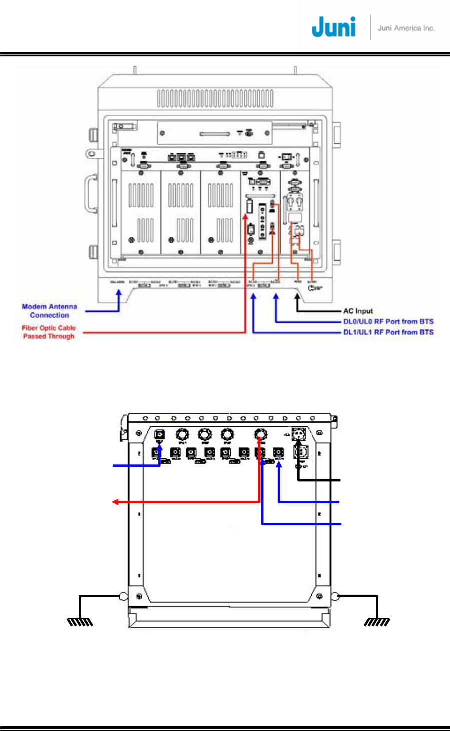
[FIGURE 3.5.11] CABLE CONNECTIONS ON THE DHU (FRONT VIEW)
[FIGURE 3.5.12] CABLE CONNECTIONS ON THE DHU (BOTTOM VIEW)
Fiber Optic Cable
Passed Through
DL1/UL1 RF Port from BTS
DL0/UL0 RF Port from BTS
AC Input
Modem Antenna
Connection
Ground Ground

JUNI JF-46-E1900/CFN03
CDMA FIBER FED REPEATER OPERATIONS MANUAL
JUNI AMERICA PROPRIETARY & CONFIDENTIAL
Revision 0.01 Juni America Inc.
38
3.5.11 Remote Unit Commissioning and Provisioning
Note: The power to the Remote Unit is then fed via the AC Female MS3102 Type
connector. The Male MS3102 Type Connector connected to the enclosure is grounded to
provide safety for installation personnel.
1. Verify that the power is switched OFF.
2. Before any other connections are made, ensure that the ground terminal on the RU
cabinet has been connected to the common ground of the installation site, as
described in the previous section.
3. Using an AC voltmeter, verify that the AC voltage level at the AC outlet is 115 or
230VAC.
4. Check that the AC power cable is earthed and is supplying the correct voltage (115 or
230VAC) and polarity and then connect it to the AC input port of the RU.
5. At the AC breaker box, close the circuit breaker for the circuit that supplies AC power
to the RU.
6. Verify that all electrical and optical connections have been completed and that all
optical fibers, coaxial cables and wires are properly routed and secured.
7. The incoming electrical line of the RU should be made waterproof and moisture proof
by using contraction tubes.
8. Connect one of the customer-supplied antenna cables to the DL/UL0 port of the RU.
Connect a second customer-supplied Antenna cables to the UL1 port of the RU.
9. Connect the optic cable to the optic module inside the RU cabinet. (As the optic input
level from the DHU would be measured during gain setup, the installer may choose
not to connect the optical fiber cable at this point.)
10. Connect the customer-supplied AC power cable to the RU AC power port. (AC power
must be turned OFF for safety.)
11. Switch the power on and check the status of power supply LED.
12. Connect a PC to the debug port of the RU with a RJ-45 cable and load the Internet
Explorer software to check the status and settings of the RU.
13. Ensure that communication between the RU and DHU is functioning correctly after
setting on the RRCU.
14. Check the downlink signal power waveform and level.
15. Close the door of the RU and weatherproof the connectors and boot.
JUNI JF-46-E1900/CFN03
CDMA FIBER FED REPEATER OPERATIONS MANUAL
JUNI AMERICA PROPRIETARY & CONFIDENTIAL
Revision 0.01 Juni America Inc.
39
OPTIC
AC_IN UL_1
DL/UL_0 BATTERY(Max 0.7A)
NMS
350_IN UL0_IN
NMS DL_OUTUL1_IN 320_OUT
SPT-JF46
Remote_Optic Module
3
Fiber Optic Cable
Passed Through
AC Input
Battery Cable
UL_1 RF Port
DL/UL_0 RF Port
[FIGURE 3.5.13] CABLE CONNECTIONS FOR THE REMOTE UNIT (TOP VIEW)
Ground
BATTERY(Max 0.7A)
OPTIC
AC_IN DL/UL_0 UL_1
FAN
A
B
D
C
E
F
Fiber Optic Cable
Passed Through
AC Input Battery Cable
UL_1 RF Port
DL/UL_0 RF Port
Ground
[FIGURE 3.5.14] CABLE CONNECTIONS FOR THE REMOTE UNIT (BOTTOM VIEW)
JUNI JF-46-E1900/CFN03
CDMA FIBER FED REPEATER OPERATIONS MANUAL
JUNI AMERICA PROPRIETARY & CONFIDENTIAL
Revision 0.01 Juni America Inc.
40
3.5.12 Operations Tests
This section provides test procedures for the uplink and downlink required to be
undertaken in order to set up the JF-46 for optimal service.
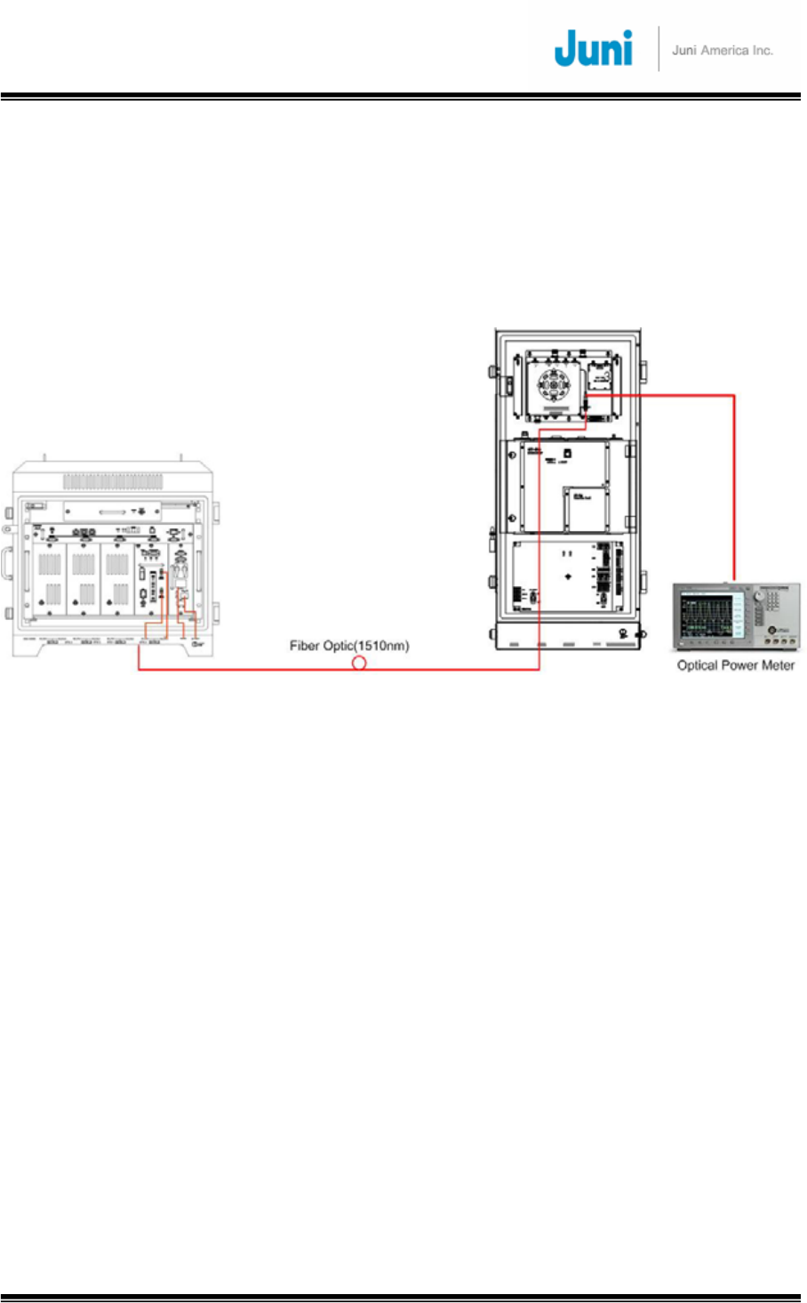
3.5.12.1 Optic Cable Loss Test
Connect the system as shown below:
[FIGURE 3.5.15] CONNECTION TO PERFORM OPTIC CABLE LOSS TEST
Check optic cable loss by using an optic power meter or reflectometer
1. With the DHU on, connect the power meter to the optic module of the RU and
measure the Forward (1510nm) output level. If the optic input level exceeds +7dBm,
check the DHU optic module.
2. If the optic loss is greater than –8dBo (on the basis of 1510nm, optic loss = donor
output optic power – remote input optic power) and the optic cable length between
the DHU and RU is less than 15 miles, check for faults in the PD (Photo Diode) or
check the optic cable.
3. If the optic loss is lesser than –2dBo (on the basis of 1510nm, optic loss = donor
output optic power – remote input optic power), add the optic jumper cable(2dBo).
4. If a PD fault has occurred, inspect the optic input level and check the optic line. Clean
the optic connector and if the fault is still existent, contact Juni technical support.
* Reference
Optic cable loss is 0.25dB/km at 1510nm, and connection loss is 0.4dB/connector. The total
optic loss due to the connector is about 1 to 2dB. (0.4dB ×2 (connector)
=
approx 1dB)

JUNI JF-46-E1900/CFN03
CDMA FIBER FED REPEATER OPERATIONS MANUAL
JUNI AMERICA PROPRIETARY & CONFIDENTIAL
Revision 0.01 Juni America Inc.
41
3.5.13 Setup Procedure for DL/UL Path Gain
This section provides test procedures for the uplink and downlink required to be
undertaken in order to set up the JF-46 for optimal service.
The table below provides initial settings for three BTS and RU configurations:
(1) One 1x RTT carrier at 16 Watts output at BTS, 30 Watts output at RU
(2) One 1xRTT carrier at 16 Watts plus one 1xEV-DO carrier at 16 Watts at BTS, 40
Watts output at RU
(3) Two 1xRTT carriers at 16 Watts each at BTS, 40 Watts output at RU
For all three configurations above, the External Loss between BTS and Donor Hub
Unit is 37 dB total. For all three configurations, the desired target value of UL gain
from RU antenna port to BTS RF port is 0 dB.
Please see section 4 and the “Initial Configuration and Set Up Method of Procedure”
for a detailed explanation to what each setting denotes.
JUNI JF-46-E1900/CFN03
CDMA FIBER FED REPEATER OPERATIONS MANUAL
JUNI AMERICA PROPRIETARY & CONFIDENTIAL
Revision 0.01 Juni America Inc.
42
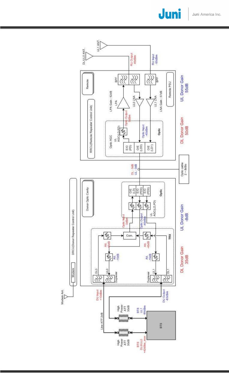
[FIGURE 3.5.16] ONE CARRIER TOTAL OUTPUT POWER OF +45DBM
JUNI JF-46-E1900/CFN03
CDMA FIBER FED REPEATER OPERATIONS MANUAL
JUNI AMERICA PROPRIETARY & CONFIDENTIAL
Revision 0.01 Juni America Inc.
43
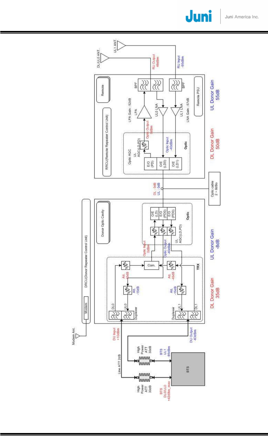
[FIGURE 3.5.17] TWO CARRIER TOTAL OUTPUT POWER VALUE OF +46DBM
JUNI JF-46-E1900/CFN03
CDMA FIBER FED REPEATER OPERATIONS MANUAL
JUNI AMERICA PROPRIETARY & CONFIDENTIAL
Revision 0.01 Juni America Inc.
44
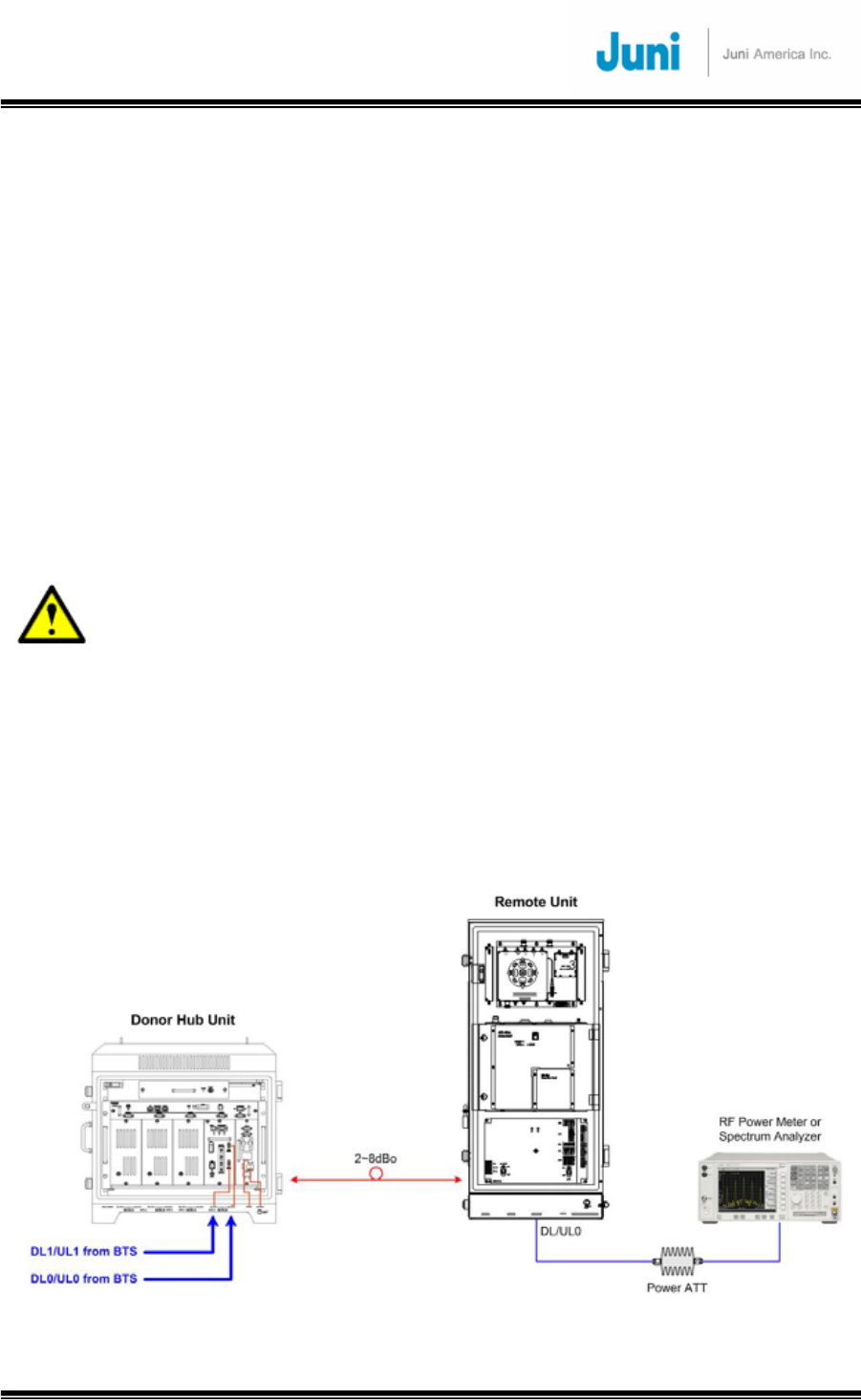
3.5.13.1 Setup for DL Gain
The procedures provided below can be used to fine-tune the DHU and RU DL settings to
obtain the desired RU Pilot Power output.
a. Refer to Figure 3.5.20 below. Set up the BTS for Pilot-only transmission. Verify with a
Power Meter or Spectrum Analyzer that the DL input power level to the DHU (to be
connected at the DL0/UL0 port of the DHU) is appropriate, given the BTS Pilot-only
output power shown in the table and External Loss value.
b. Turn on the LPA with the GUI
c. While monitoring the forward output power measurement function of the GUI (and
optionally while measuring the Remote Unit RF output using Power Attenuator and
Spectrum Analyzer or Power Meter, adjust the Remote DL ATT setting to obtain the
desired exact RU RF output value shown above.
Caution:
● The power attenuator is needs to be rated at >500W. Using a lower rating
power attenuator can fail and cause damage to the spectrum analyzer.
d. Turn off the LPA with the GUI.
e. Disconnect the Power Attenuator and Spectrum Analyzer or Power Meter.
f. This completes the DL setup.
Note: The Maximum RU output power should not exceed +46 dBm or 40 watts
composite during operation to prevent damage to the FFR.
[FIGURE 3.5.18] CONNECTION TO SET UP DL GAIN
JUNI JF-46-E1900/CFN03
CDMA FIBER FED REPEATER OPERATIONS MANUAL
JUNI AMERICA PROPRIETARY & CONFIDENTIAL
Revision 0.01 Juni America Inc.
45
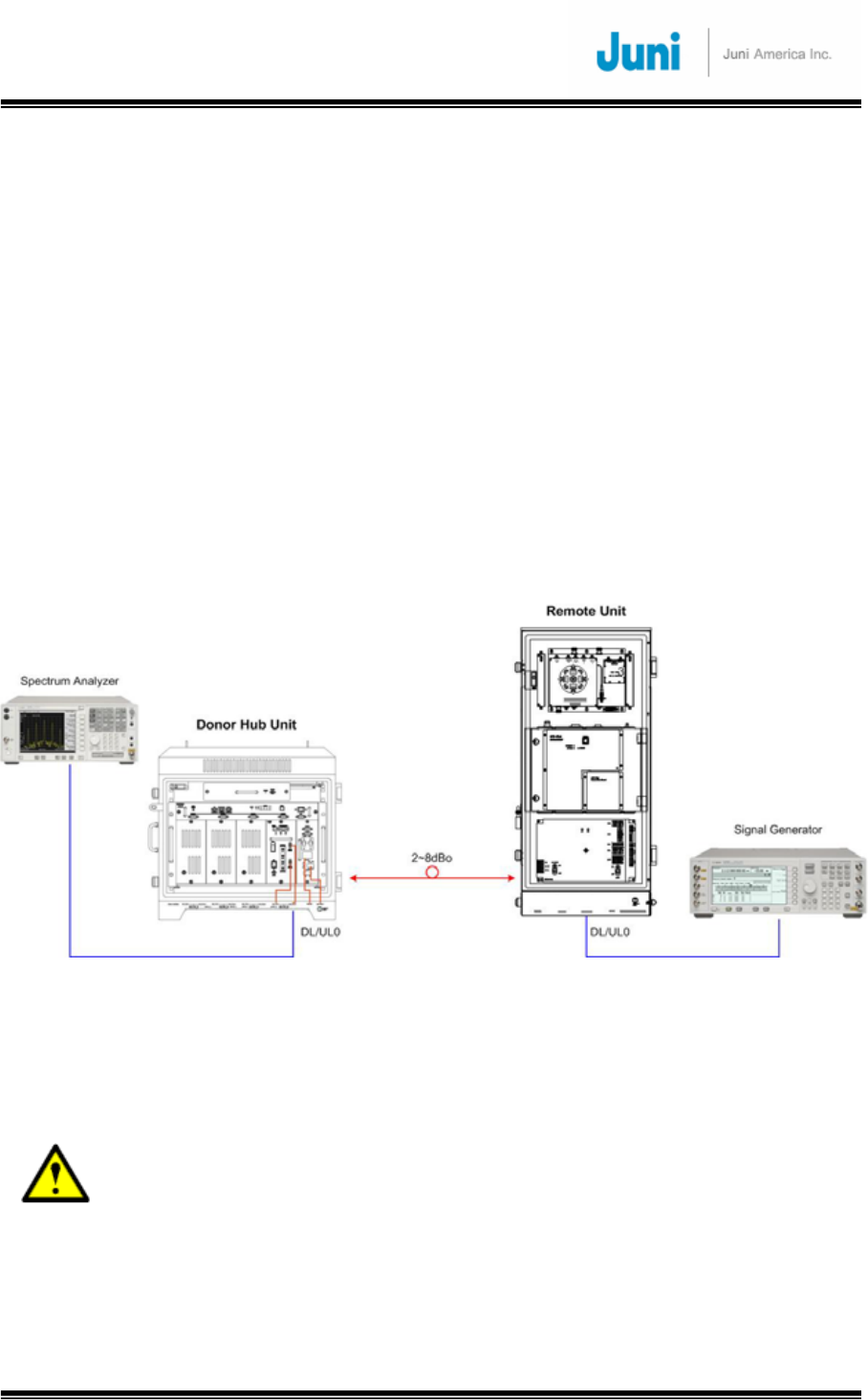
3.5.13.2 Setup for UL Gain
The procedures provided below can OPTIONALLY be used to fine-tune the DHU and RU
UL settings to obtain the exact desired UL Gain.
a. Refer to Figure 3.5.21. Connect a Spectrum Analyzer to the DL0/UL0 port of the DHU
(Span: 5 MHz, Amplitude Offset = measurement cable loss)
b. Inject an Uplink input signal of -95 dBm at the DL/UL_0 port of the RU, and check the
output level on the Spectrum Analyzer.
c. Based on the above measurements, adjust the Donor UL0 ATT control to obtain an
output power value of 32 dB, which corresponds to 0 dB overall Gain with 32 dB
External Loss
d. Repeat the above procedure for the DL1/UL1 port of the DHU, DL/UL_1 port of the
RU, and Donor UL1 ATT control.
e. This completes the UL setup.
[FIGURE 3.5.19] CONNECTION TO SET UP UL GAIN
Note: The procedure is the same for the receive diversity
3.5.13.3 Caution Items
● When adjusting the forward gain, start from the minimum gain setting.
● Max. Output Power should not exceed 40W (about +46dBm),
● When adjusting output levels while monitoring the CDMA test equipments,
input the appropriate offset level in the Spectrum Analyzer considering the Cable
Loss. (offset value = coupling value + measured cable loss)

JUNI JF-46-E1900/CFN03
CDMA FIBER FED REPEATER OPERATIONS MANUAL
JUNI AMERICA PROPRIETARY & CONFIDENTIAL
Revision 0.01 Juni America Inc.
46
3.6 Replacement of Faulty Units
Please follow the procedure to replace faulty or failed components and units. The unit
replacement procedure is common to both the DHU and RU.
3.6.1 Remote/Donor Unit Replacement
1. For RU replacement, turn off the LPA of the RU
2. Turn off the power of the RU or DHU
3. Disconnect all cables from the faulty unit
Note: The antenna cables must be disconnected after the repeater has been turned
‘OFF’
4. Dismount the faulty unit
5. Mount the replacement unit
6. Connect all cables to the replaced unit
7. Turn on the power of the replaced unit
8. For RU replacement, check whether the LPA is off (Turn it off if it is on), and
configure the settings of the replaced unit. These settings should be identical to
the previous faulty unit settings while it was under service
9. For RU replacement, turn on the LPA of the RU
3.6.2 Optical Module Replacement
1. Turn off the OTRU of the DHU power supply
2. Disconnect al RF connectors, power cable, data cable and optical fiber that are
connected to the OTRU
3. Unscrew the multi-turn fastener located at the top and bottom of the module and
pull on the handle to free the OTRU
4. Completely remove the module from its slot and place the replacement module
back into the same position being careful not to bump the OTRU
5. Tighten the multi-turn fastener and reconnect all cables and connectors
JUNI JF-46-E1900/CFN03
CDMA FIBER FED REPEATER OPERATIONS MANUAL
JUNI AMERICA PROPRIETARY & CONFIDENTIAL
Revision 0.01 Juni America Inc.
47
3.7 Storage of the Repeater
• When storing the repeater, it is recommended to pack the repeater in its original
package supplied by Juni America.
• The repeater should not be stored in a high temperature or humid environment and
avoid direct sunlight.
3.8 Safety Precautions
To avoid the risk of accidental electric shock, do not touch the contact terminals
on the power supply unit or the control board during normal operation. If
replacement for a component is required, the power of the repeater should be
turned ‘OFF’ before taking any action.
To avoid the risk of accidental fire or electric shock, do not expose this product
to rain or any other wet condition.
Only a qualified technician should service this repeater. Opening or removing
covers may expose you to dangerous voltages, radiation and/or other risks.
Incorrect assembly may cause electric shock when the unit is subsequently
used.
Only authorized technician should connect or disconnect the Battery. The
Battery Switch of Power Supply of the repeater should be turned ‘OFF’ before
connecting or disconnecting the Battery. When the Battery is not connected, the
Battery Switch should be turned ‘OFF’.

JUNI JF-46-E1900/CFN03
CDMA FIBER FED REPEATER OPERATIONS MANUAL
JUNI AMERICA PROPRIETARY & CONFIDENTIAL
Revision 0.01 Juni America Inc.
48
4. Operation
This section provides guidelines for operating the JF-46 system via GUI interfaces.
Information is provided on how to verify the units are operating properly and whether
performance requirements are satisfied. This process assumes that the units have
been installed in accordance with the system design plan.
Please refer to the “Initial System Configuration and Set up Method of Procedure”
document for a step by step guide to provision the FFR.
4.1 Introduction
The process of turning on the system and verifying operation involves powering up
various site names and adjusting the RF signal levels. The operator can control and
monitor the system parameters by using the Web GUI.(Internet Explorer)
4.2 Web GUI Operation
4.2.1 Introduction
The JF-46 repeater can be controlled via the Web GUI(using Internet Explorer). This
enables the operator to monitor and control the repeater by connecting a PC to the
repeater via a linked or wireless communication protocol. Connect the PC to the LMT
port(Ethernet) on the DRCU with the RJ-45 cable. The technician should be at the
DHU site location to view the status of the RU’s.
JUNI JF-46-E1900/CFN03
CDMA FIBER FED REPEATER OPERATIONS MANUAL
JUNI AMERICA PROPRIETARY & CONFIDENTIAL
Revision 0.01 Juni America Inc.
49
4.2.2 WEB GUI Connection
1) Using RJ-45 Ethernet cable, connect from LMT port on the front of the Donor unit
to Ethernet port of your PC.
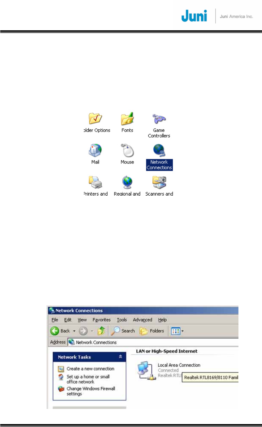
2) First we need to find the TCP/IP properties window. Open the control panel and
click the “Network Connections” icon.
[FIGURE 4.2.1] OPEN THE CONTROL PANEL
3) The Network connections window will open. All of your available network
connections will be listed. I only have one network interface listed, which is my Local
Area Network (LAN) card. You could have several options listed here both physical
connections and virtual. For example if you had a wireless network car, and a wired
network card, you would see both of these listed. An example of a virtual connection,
meaning that there is no physical adapter, would be a Virtual Private Network (VPN).
VPN’s are well beyond the scope of the tutorial, but I wanted to give you an example
of the icons that you may see. My listing is pictured below.
[FIGURE 4.2.2] NETWORK CONNECTIONS
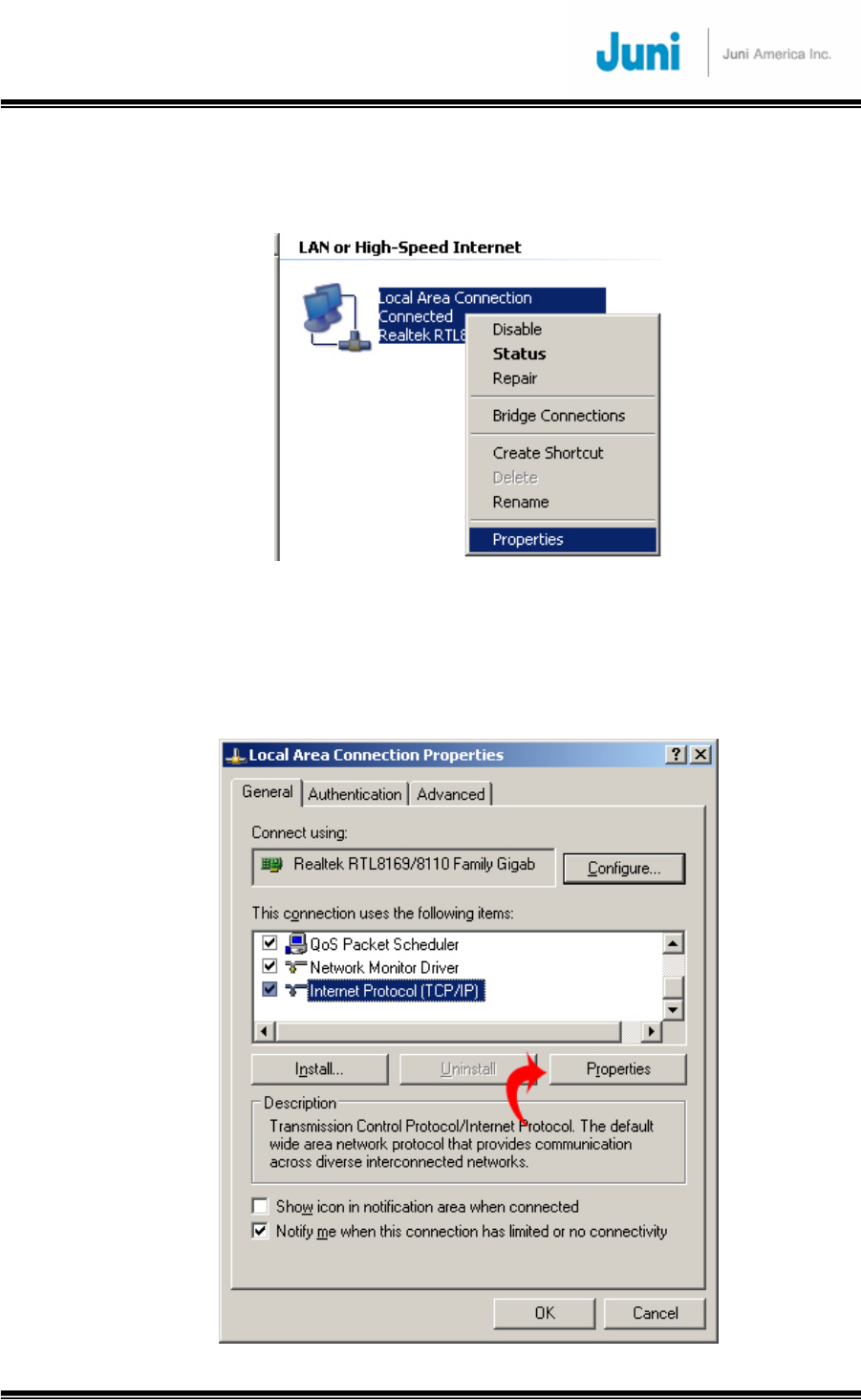
JUNI JF-46-E1900/CFN03
CDMA FIBER FED REPEATER OPERATIONS MANUAL
JUNI AMERICA PROPRIETARY & CONFIDENTIAL
Revision 0.01 Juni America Inc.
50
4) I will be explaining the settings of a standard wired connection. Right click on your
Local Area Network connection and select properties.
[FIGURE 4.2.3] NETWORK PROPERTIES
5) In the Local Area Connection Properties window find the box that reads “This
connection uses the following items.” Use the scroll bar to locate the “Internet
Properties (TCP/IP)” then highlight it and click the properties button.
[FIGURE 4.2.4] INTERNET PROTOCOL(TCP/IP)
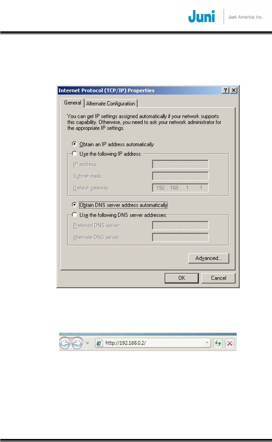
JUNI JF-46-E1900/CFN03
CDMA FIBER FED REPEATER OPERATIONS MANUAL
JUNI AMERICA PROPRIETARY & CONFIDENTIAL
Revision 0.01 Juni America Inc.
51
6) When the options “Obtain an IP address automatically” and “Obtain DNS server
address automatically are selected, your computer will be set to operating using
DHCP. DHCP stands for Dynamic Host Configuration Protocol
[FIGURE 4.2.5] INTERNET PROTOCOL(TCP/IP) PROPERTIES
7) Run “Internet Explorer” and type the IP address as below.
LMT Default Address: 192.168.0.2
[FIGURE 4.2.6] DEFAULT ADDRESS

JUNI JF-46-E1900/CFN03
CDMA FIBER FED REPEATER OPERATIONS MANUAL
JUNI AMERICA PROPRIETARY & CONFIDENTIAL
Revision 0.01 Juni America Inc.
52
4.2.3 Repeater Log In
When you see the webpage as below, type the proper user ID and password. The
user ID has three categories such as administrator, operator and viewer. Depending
on user ID, the display of window will be different.
[FIGURE 4.2.7] REPEATER GUI LOG IN
4.2.4 Default Usernames and Passwords
ENTER USER NAME AND PASSWORD HERE.
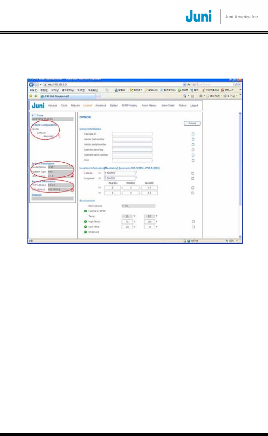
JUNI JF-46-E1900/CFN03
CDMA FIBER FED REPEATER OPERATIONS MANUAL
JUNI AMERICA PROPRIETARY & CONFIDENTIAL
Revision 0.01 Juni America Inc.
53
4.2.5 Initial Window
When you log in, the initial screen is as below.
[FIGURE 4.2.8] INITIAL WINDOW
1) System Configuration:: It automatically displays whether OTRU has been
installed or not.
2) System Information: It displays model name, system type and GUI version.
3) Network Information: It displays WIP address and LIP address.
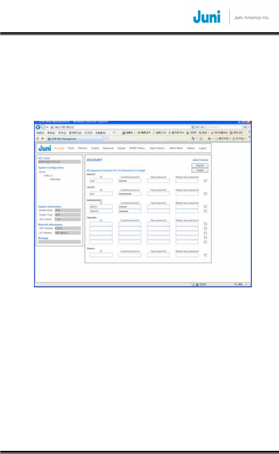
JUNI JF-46-E1900/CFN03
CDMA FIBER FED REPEATER OPERATIONS MANUAL
JUNI AMERICA PROPRIETARY & CONFIDENTIAL
Revision 0.01 Juni America Inc.
54
4.2.6 Account Window
Figure 4.2.3 shows the Account window. There are three user IDs for administrator,
operator and viewer. The administrator can control and monitor all the functions. And
the administrator can also create and delete user IDs and passwords of operator and
viewer. The administrator is allowed to create five accounts for operator and two
accounts for viewer.
[FIGURE 4.2.9] ACCOUNT WINDOW
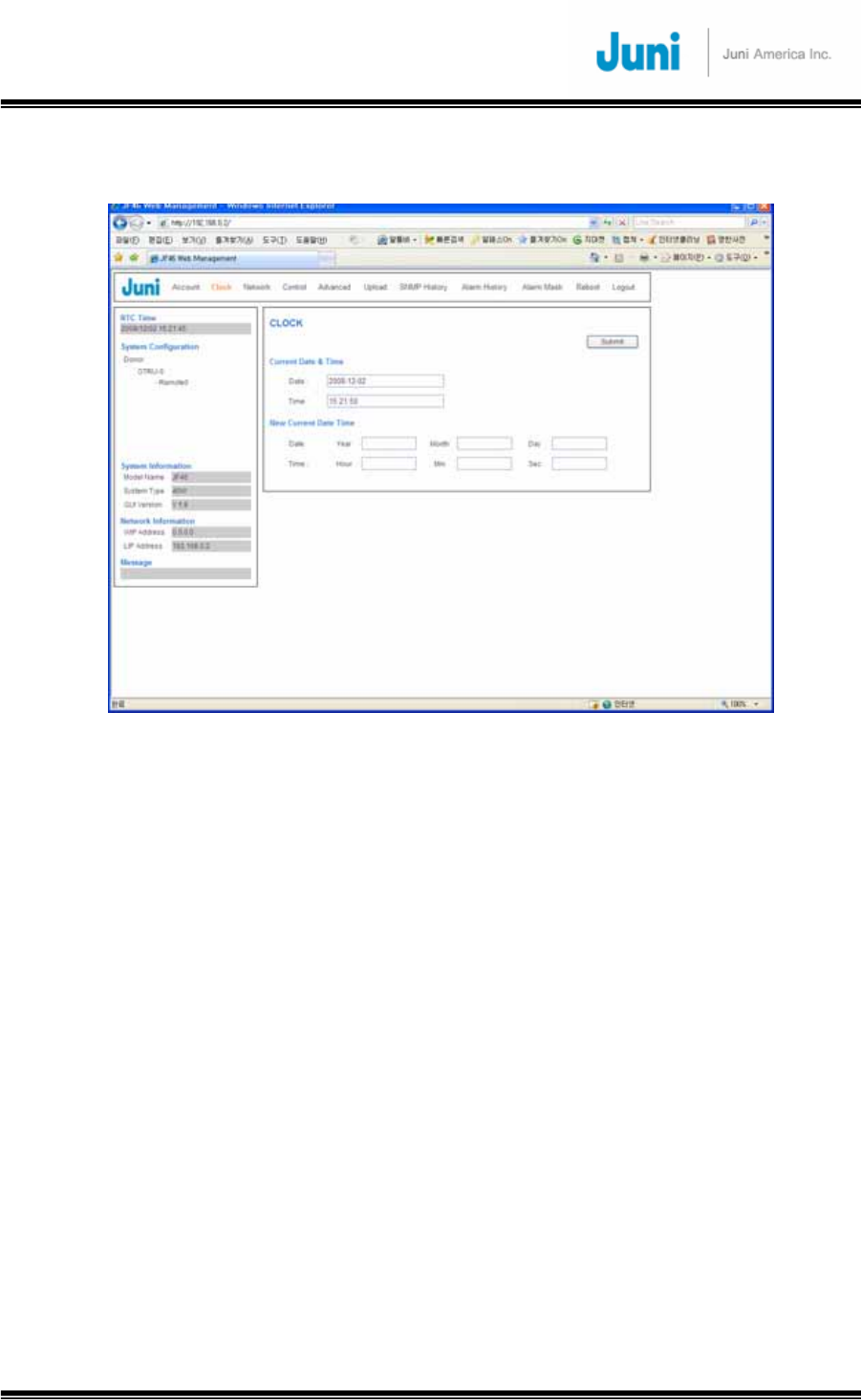
JUNI JF-46-E1900/CFN03
CDMA FIBER FED REPEATER OPERATIONS MANUAL
JUNI AMERICA PROPRIETARY & CONFIDENTIAL
Revision 0.01 Juni America Inc.
55
4.2.7 Clock Window
[FIGURE 4.2.10] CLOCK WINDOW

JUNI JF-46-E1900/CFN03
CDMA FIBER FED REPEATER OPERATIONS MANUAL
JUNI AMERICA PROPRIETARY & CONFIDENTIAL
Revision 0.01 Juni America Inc.
56
4.2.8 Network Window
This menu is for setting network configuration. Using this menu, you can configure
TCP/IP for each interface and SNMP items.
[FIGURE 4.2.11] NETWORK WINDOW
4.2.9 Control Window
To view the status of installed repeaters, double click on the desired repeater in
Figure 4.2.4 to bring up the Status and Control Window. This can also be done by
right-clicking on the desired repeater and selecting the “Status & Control” command
as shown in Figure 4.2.6.
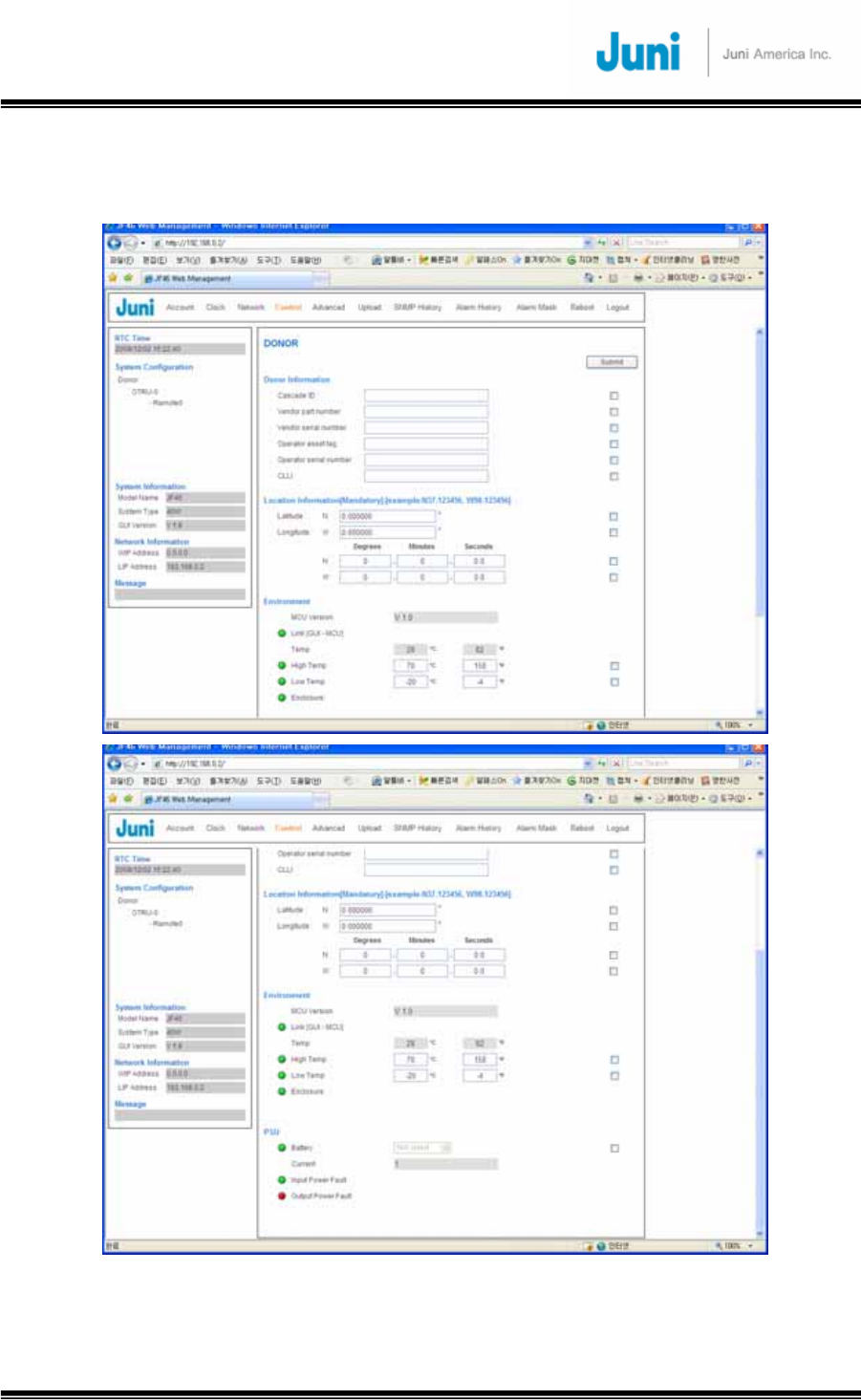
JUNI JF-46-E1900/CFN03
CDMA FIBER FED REPEATER OPERATIONS MANUAL
JUNI AMERICA PROPRIETARY & CONFIDENTIAL
Revision 0.01 Juni America Inc.
57
4.2.9.1 Donor Control Window
[FIGURE 4.2.12] DONOR CONTROL WINDOW
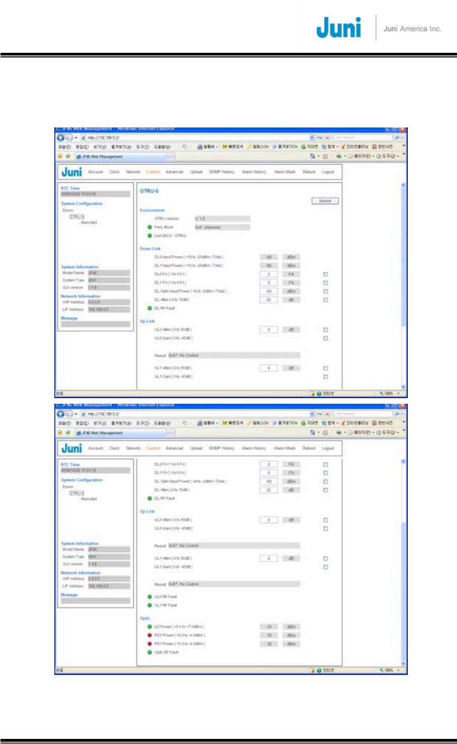
JUNI JF-46-E1900/CFN03
CDMA FIBER FED REPEATER OPERATIONS MANUAL
JUNI AMERICA PROPRIETARY & CONFIDENTIAL
Revision 0.01 Juni America Inc.
58
4.2.9.2 OTRU Control Window
[FIGURE 4.2.13] OTRU CONTROL WINDOW
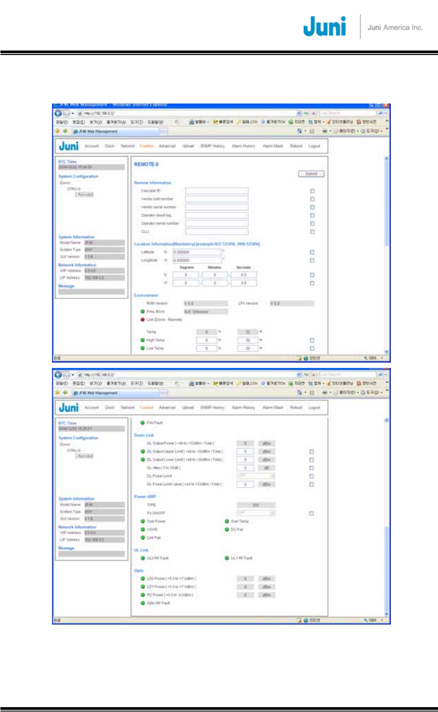
JUNI JF-46-E1900/CFN03
CDMA FIBER FED REPEATER OPERATIONS MANUAL
JUNI AMERICA PROPRIETARY & CONFIDENTIAL
Revision 0.01 Juni America Inc.
59
4.2.9.3 Remote Control Window
[FIGURE 4.2.14] REMOTE CONTROL WINDOW
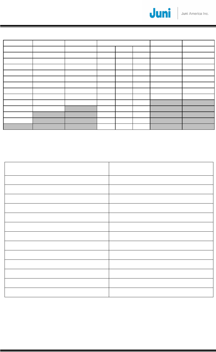
JUNI JF-46-E1900/CFN03
CDMA FIBER FED REPEATER OPERATIONS MANUAL
JUNI AMERICA PROPRIETARY & CONFIDENTIAL
Revision 0.01 Juni America Inc.
60
normal 5MHz normal 15MHz normal 20MHz 5+15 15+5
A1 A A,D A1+A2 D+B3 E+F A1+(A3,D,B1) A+B1
A2 A2,A3,D A2,A3,D,B1 A1+A3 D+E E+C1 A2+(D,B1,B2) (A2,A3,D)+B2
A3 A3,D,B1 A3,D,B1,B2 A1+D B1+B2 E+C2 A3+ B (A3,D,B1)+B3
D D,B1,B2 D,B A1+B1 B1+B3 E+C3 D+(B2,B3,E) (D,B1,B2)+E
B1 B B,E A2+A3 B1+E F+C1 B1+(B3,E,F) B+F
B2 B2,B3,E B2,B3,E,F A2+D B1+F F+C2 B2+(E,F,C1) (B2,B3,E)+C1
B3 B3,E,F B3,E,F,C1 A2+B1 B2+B3 F+C3 B3+(F,C1,C2) (B3,E,F)+C2
E E,F,C1 E,F,C1,C2 A2+B2 B2+E F+G E+C (E,F,C1)+C3
F F,C1,C2 F,C A3+D B2+F C1+C2 F+(C2,C3,G) (F+C1,C2)+G)
C1 C C,G A 3+B1 B2+C1 C1+C3
C2 C2,C3,G A3+B2 B3+E C1+G
C3 A 3+B3 B3+F C2+C3
G D+B1 B3+C1 C2+G
D+B2 B3+C2 C3+G
5+5
[Table 4.2.1] 94 Possible Frequency Band Combinations
Band Frequency
A1 1850 to 1855 MHz
A2 1855 to 1860 MHz
A3 1860 to 1865 MHz
D 1865 to 1870 MHz
B1 1870 to 1875 MHz
B2 1875 to 1880 MHz
B3 1880 to 1885 MHz
E 1885 to 1890 MHz
F 1890 to 1895 MHz
C1 1895 to 1900 MHz
C2 1900 to 1905 MHz
C3 1905 to 1910 MHz
G 1910 to 1915 MHz
[Table 4.2.2] Frequency band ranges corresponding to Table 4.2.1
Note: Frequencies C1, C2, C3 are identical to FCC’s C3, C4, and C5.
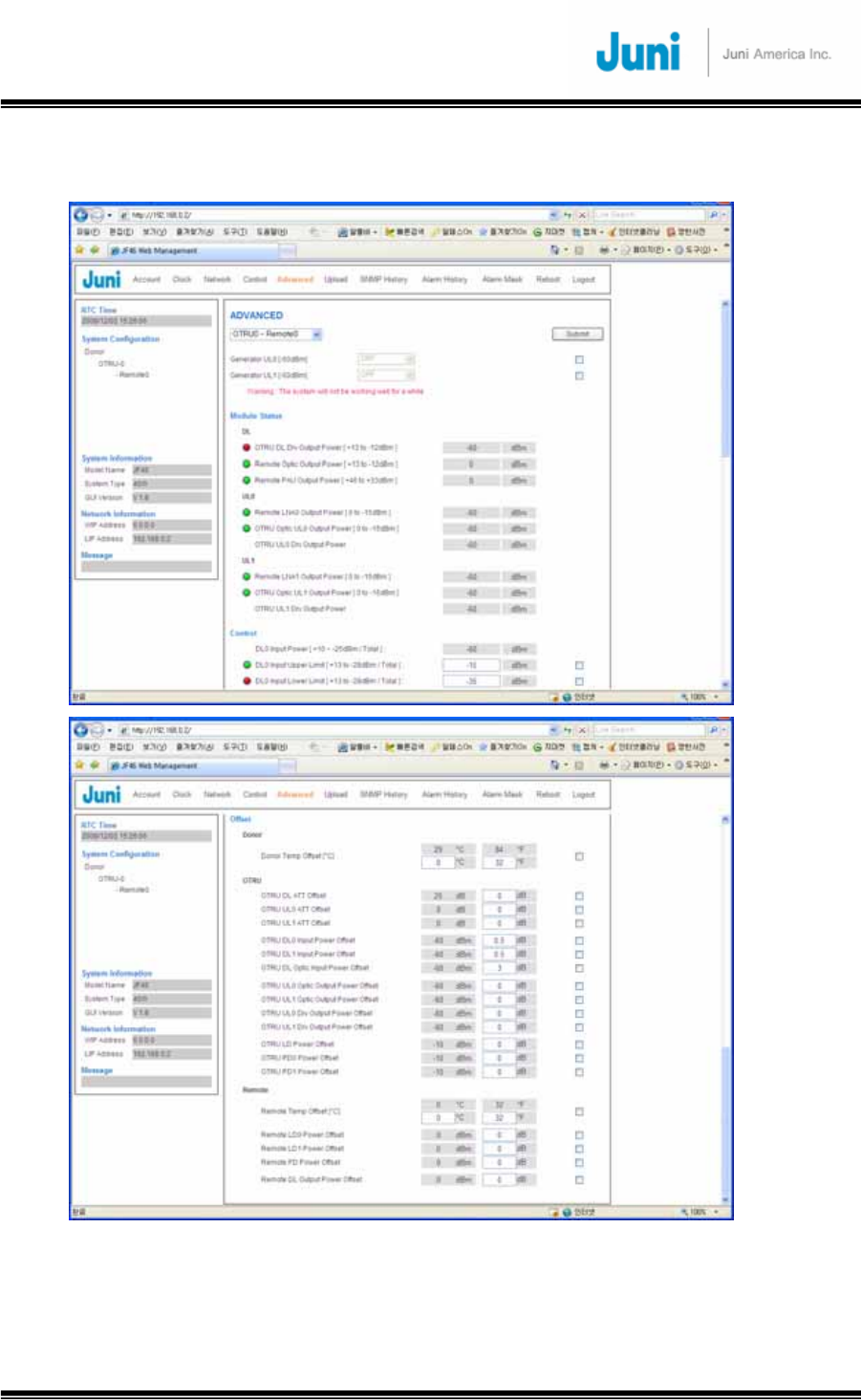
JUNI JF-46-E1900/CFN03
CDMA FIBER FED REPEATER OPERATIONS MANUAL
JUNI AMERICA PROPRIETARY & CONFIDENTIAL
Revision 0.01 Juni America Inc.
61
4.2.10 Advanced Window
[FIGURE 4.2.15] ADVANCED WINDOW
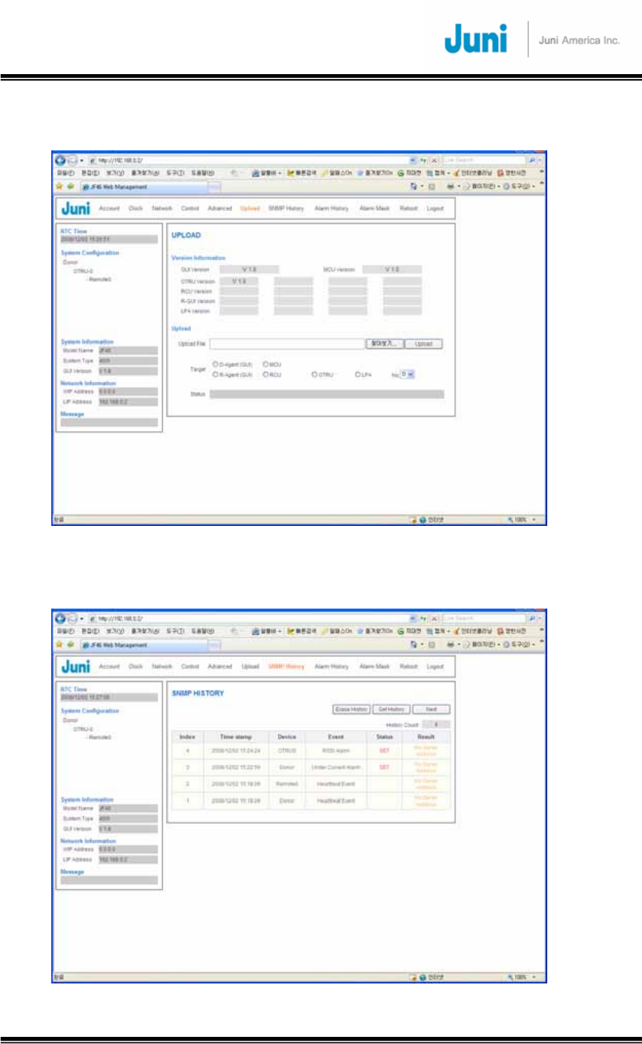
JUNI JF-46-E1900/CFN03
CDMA FIBER FED REPEATER OPERATIONS MANUAL
JUNI AMERICA PROPRIETARY & CONFIDENTIAL
Revision 0.01 Juni America Inc.
62
4.2.11 Upload Window
[FIGURE 4.2.16] UPLOAD WINDOW
4.2.12 SNMP History Window
[FIGURE 4.2.17] SNMP HISTORY WINDOW

JUNI JF-46-E1900/CFN03
CDMA FIBER FED REPEATER OPERATIONS MANUAL
JUNI AMERICA PROPRIETARY & CONFIDENTIAL
Revision 0.01 Juni America Inc.
63
4.2.13 Alarm History Window
[FIGURE 4.2.18] ALARM HISTORY WINDOW
4.2.14 Alarm Mask Window
[FIGURE 4.2.19] ALARM MASK WINDOW
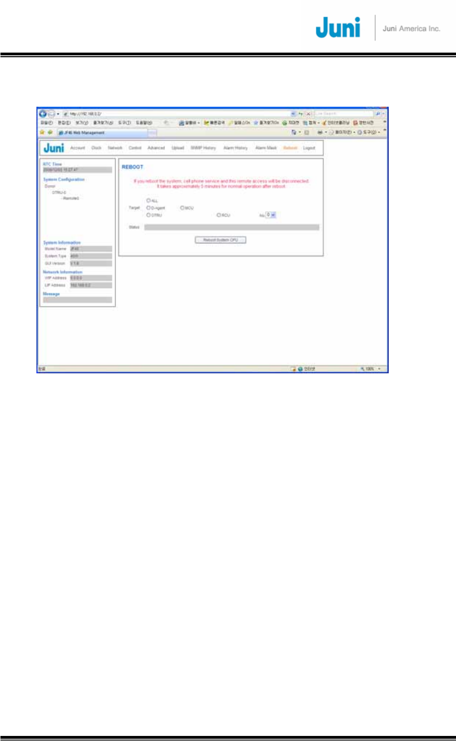
JUNI JF-46-E1900/CFN03
CDMA FIBER FED REPEATER OPERATIONS MANUAL
JUNI AMERICA PROPRIETARY & CONFIDENTIAL
Revision 0.01 Juni America Inc.
64
4.2.15 Reboot Window
[FIGURE 4.2.20] REBOOT WINDOW
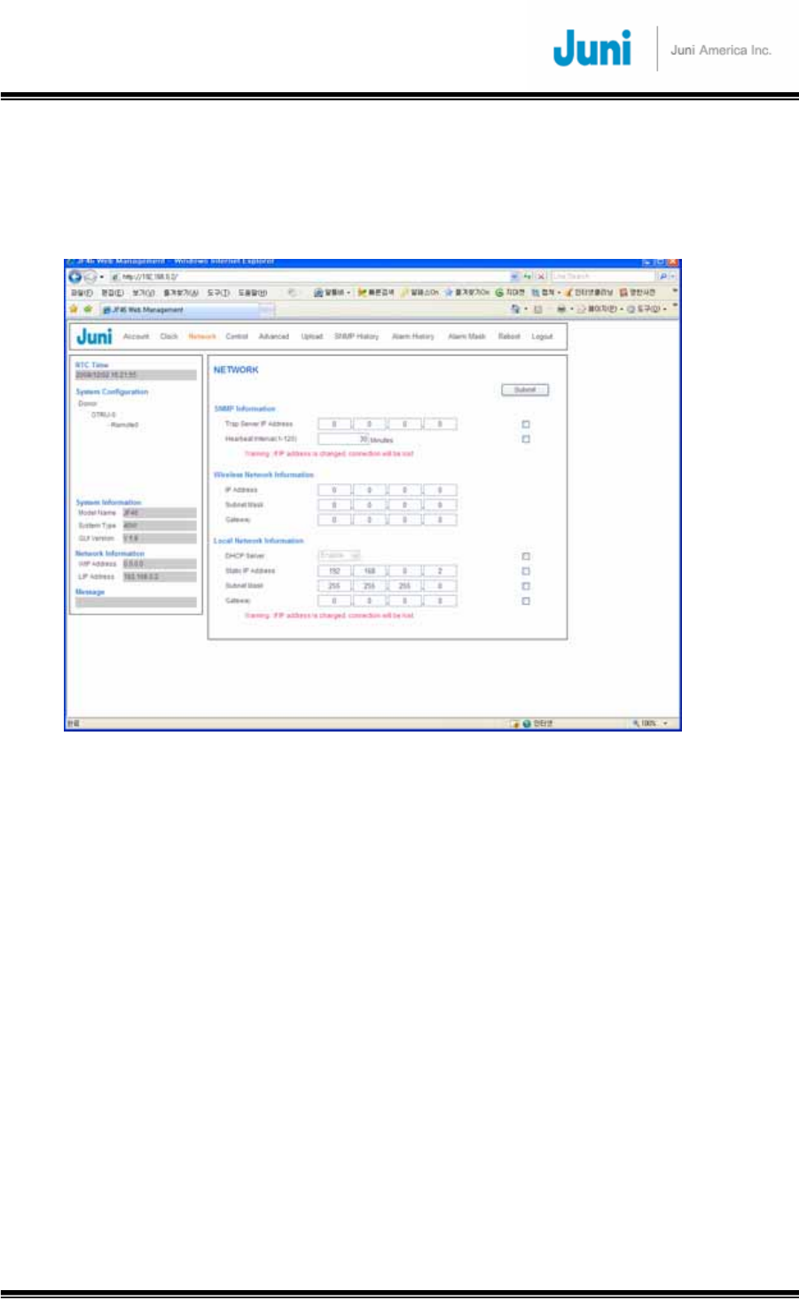
JUNI JF-46-E1900/CFN03
CDMA FIBER FED REPEATER OPERATIONS MANUAL
JUNI AMERICA PROPRIETARY & CONFIDENTIAL
Revision 0.01 Juni America Inc.
65
4.3 Network Menu
This menu is for setting network configuration. Using this menu, you can configure
TCP/IP for each interface and SNMP items.
[FIGURE 4.3.1] NETWORK MENU
4.3.1 SNMP Configuration
4.3.1.1 Introduction
The DHU utilizes a wireless CDMA modem connected to the SNMP agent to transmit
SNMP TRAPs and INFORMs to a central Sprint EMS (Element Management Server)
on the Sprint private network. The TRAPs, or commonly referred to as a heartbeat,
are sent at an interval of every 1 ~ 120 minutes and is a method of notifying the EMS
that the repeater is still connected to the network and is functioning correctly.
INFORMs are transmitted when an alarm at a RU occurs. The INFORM is sent to the
EMS providing information on the type of alarm that has occurred and the repeater it
originates from.
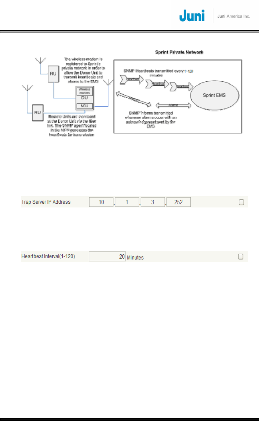
JUNI JF-46-E1900/CFN03
CDMA FIBER FED REPEATER OPERATIONS MANUAL
JUNI AMERICA PROPRIETARY & CONFIDENTIAL
Revision 0.01 Juni America Inc.
66
[FIGURE 4.3.2] SNMP OPERATION OVERVIEW
4.3.1.2 Trap Server IP Address Set up
Set up EMS IP address that belongs to Sprint Private Network in order to transmit
messages for SNMP trap and inform.
[FIGURE 4.3.3] TRAP SERVER IP ADDRESS
4.3.1.3 Heartbeat Interval Set up
Set up the heartbeat interval for transmitting to EMS.
[FIGURE 4.3.4] HEARTBEAT INTERVAL
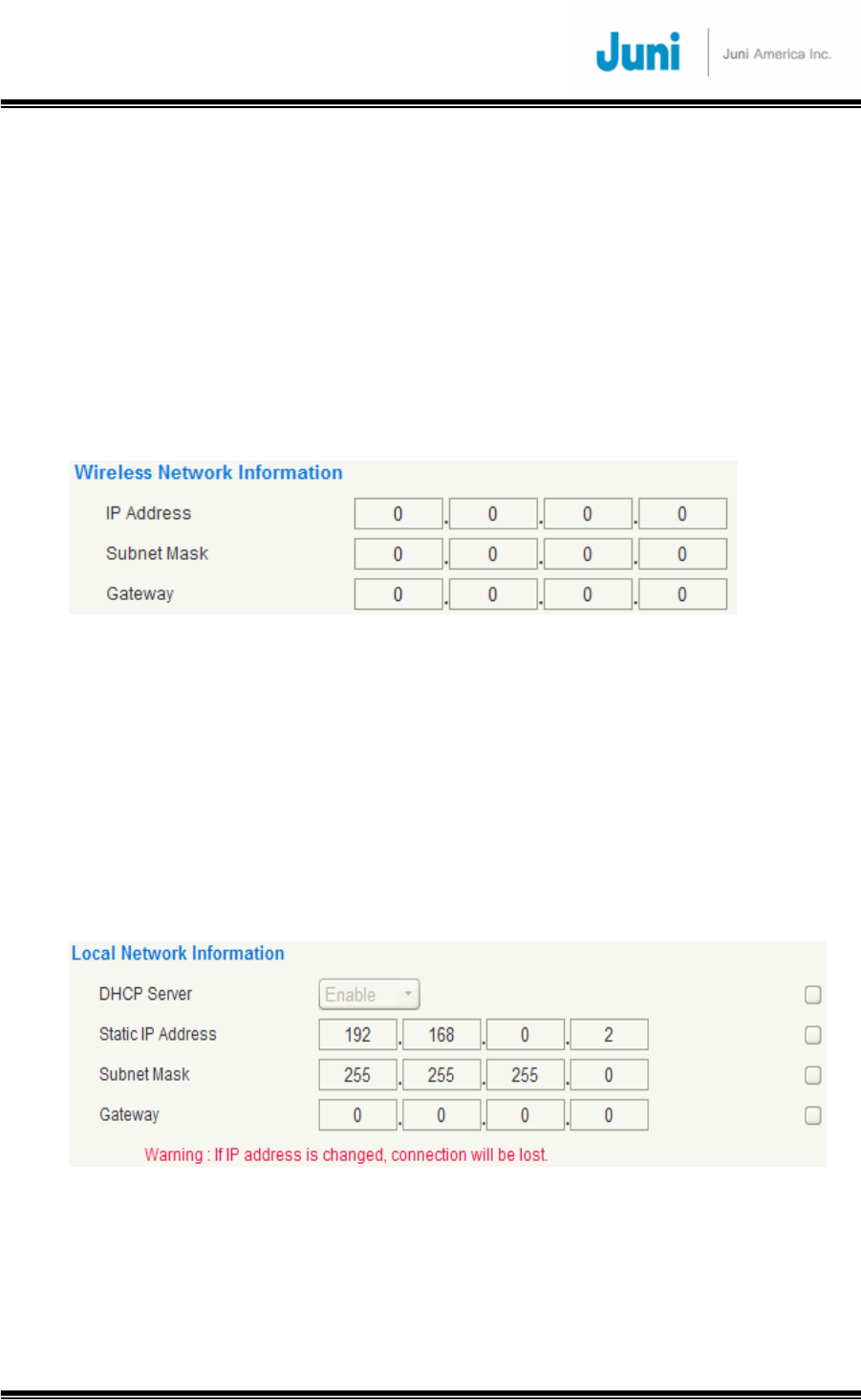
JUNI JF-46-E1900/CFN03
CDMA FIBER FED REPEATER OPERATIONS MANUAL
JUNI AMERICA PROPRIETARY & CONFIDENTIAL
Revision 0.01 Juni America Inc.
67
4.3.2 Network Set up
4.3.2.1 Wireless Network Information
The information shows the interface between CDMA modem and Sprint network. This
information is automatically assigned from DHCP server throughout CDMA modem. If
interface information shows “0.0.0.0,” there is communication problem between
CDMA modem and Sprint network. In this case, you cannot send any information of
heartbeat and alarm and it is not possible to connect Web GUI throughout Sprint
Network.
[FIGURE 4.3.5] WIRELESS NETWORK INFORMATION
4.3.2.2 Local Network Information
The user can check the information about network information of LMT port that the
user can directly connect at the site where the repeater is installed.
In order to use this interface, the user must set DHCP server to be enable and set the
“Internet Protocol Option” as “Obtain an IP address automatically” as described on
Section 4.2.2.
[FIGURE 4.3.6] LOCAL NETWORK INFORMATION
1) DHCP Server: Sets up for DHCP to be “Enable” or “Disable.” If the user sets up as
“Disable,” the user must manually set up proper IP address to connect to the Web
GUI on user’s PC.
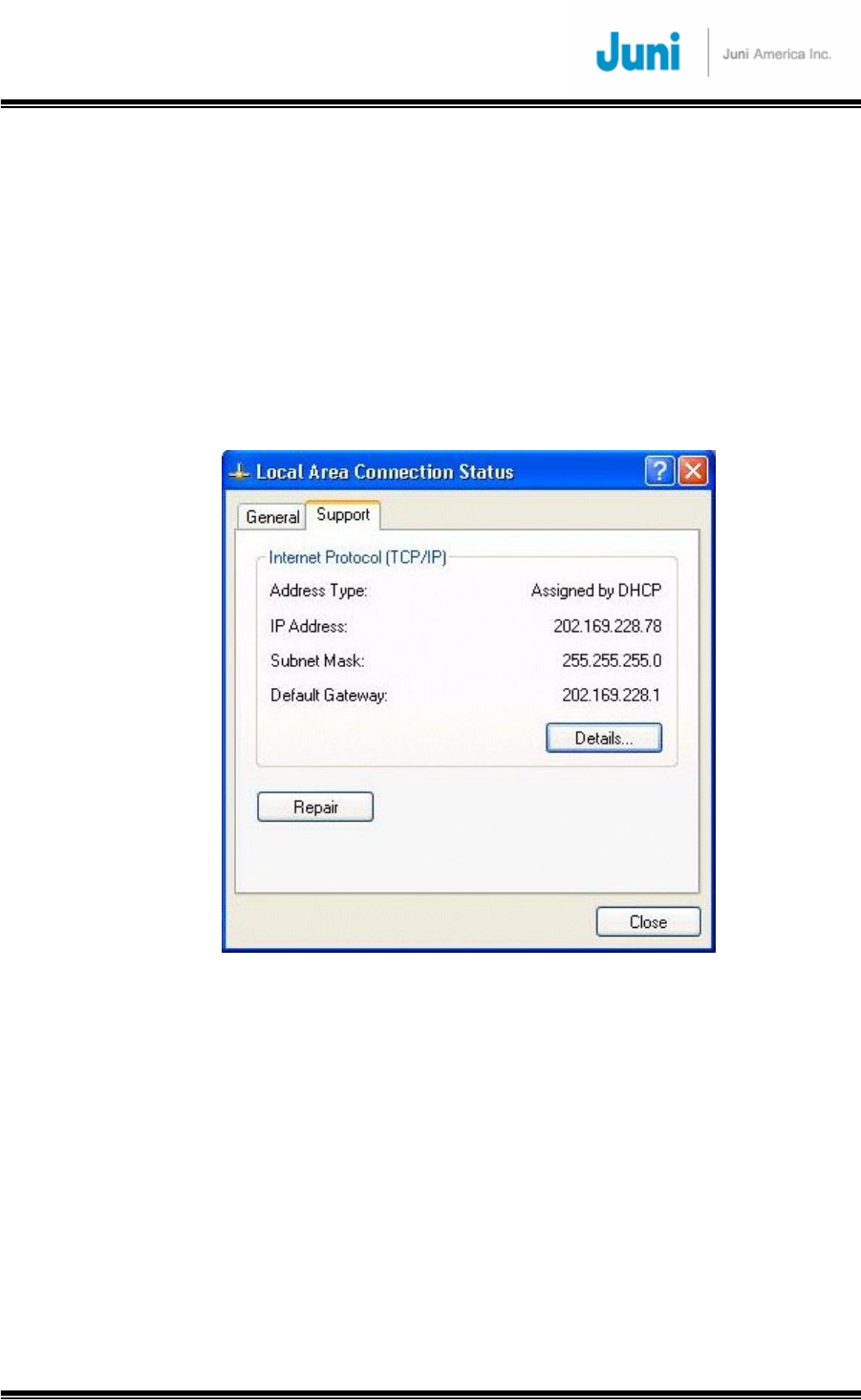
JUNI JF-46-E1900/CFN03
CDMA FIBER FED REPEATER OPERATIONS MANUAL
JUNI AMERICA PROPRIETARY & CONFIDENTIAL
Revision 0.01 Juni America Inc.
68
2) Static IP Address: If the IP address is set up for LMT port, the IP address is used
for connecting to Web GUI on web browser throughout Internet Explorer. If the user
doesn’t figure out the modification information, it can be checked on the “Local Area
Connection Status” as Figure 4.3.2.2 below.
3) Subnet Mask: Sub Network Mask for LMT port.
4) Gateway: Gateway for LMT port. The user doesn’t usually set this Gateway up.
[FIGURE 4.3.7] SNMP OPERATION OVERVIEW

JUNI JF-46-E1900/CFN03
CDMA FIBER FED REPEATER OPERATIONS MANUAL
JUNI AMERICA PROPRIETARY & CONFIDENTIAL
Revision 0.01 Juni America Inc.
69
5. System Maintenance
This section explains the JF-46 FFR system fault detection and alarm reporting
system, and provides a method for determining troubleshooting faults.
Maintenance also includes diagnosing and correcting service problems as they occur.
When an alarm is reported, it will be necessary to follow a systematic troubleshooting
procedure to determine the problem. Once the problem has been isolated, the
appropriate corrective measures must be taken to restore service. The only internal
components that can be replaced are the cooling fans, which are mounted in the DHU
and RU, and the optic module. All other failed internal components will require Juni
engineers to replace and test the units.
5.1 Periodic Maintenance
The JF-46 FFR requires minimal regular maintenance to insure continuous and
optimal operation and performance. However, it is advised that the DHU and RU are
checked often. Components that require regular replacement, cleaning, or testing
include the DHU and RU fans and backup battery. The IP55 enclosure ensures that
the JF-46 FFR can withstand all environmental influences. The following two
procedures can also be followed when a fan fails and needs to be replaced.
5.1.1 Donor Unit Fan Maintenance
1. The fan is located above the DRCU and is labeled ‘Fan Control Unit’.
2. Unplug the 24V power cable feeding the Fan Control Unit.
3. Unscrew the two multi-turn fasteners on each side of the compartment.
4. Pull out the Fan Control Unit completely from its position.
5. One fan is used to cool the DHU which will require regular maintenance by
cleaning and/or dusting.
6. Once maintenance is complete, return the Fan Control Unit back into its space
and tighten the multi-turn fasteners.
7. Plug the power cable back into the Fan Control Unit.

JUNI JF-46-E1900/CFN03
CDMA FIBER FED REPEATER OPERATIONS MANUAL
JUNI AMERICA PROPRIETARY & CONFIDENTIAL
Revision 0.01 Juni America Inc.
70
5.1.2 Remote Unit Fan Maintenance
1. The fan compartment is located at the bottom of the RU.
2. Remove the fan power cable underneath the RU.
3. By turning the stud on the side, remove the cover and pull out the fan
compartment carefully. Do not pull on it too hard. It will cause a 24V power cable
to be jammed.
4. There are two fans in the compartment which is required to be cleaned and
checked regularly to ensure proper operation of the fan and allow the fan to
perform its duty in cooling the RU.
5. At the completion of the maintenance, return the fan compartment by sliding it
back into its designated placement.
5.2 Fault Detection and Alarm Reporting
The JF-46 FFR on board embedded software detects various unit and system faults
which generate either a Major or Minor alarm. A major alarm indicates that the
repeater has failed in a way that directly affects RF transport performance. When a
major alarm occurs, all RF functions are affected and will cause the system to be out
of service. A minor alarm means that the system performance is not affected, or in
some cases, that the performance may no longer be optimal. When a minor alarm
occurs, RF functions continue and the system remains in service.
The following means are used to report major and minor alarms.
• DHU LED’s
• Web GUI(Graphical User Interface)
The DHU front panel LED indicators show status and alarm information by displaying
various colors; green, red and off.
The Web GUI provides both a summary and detailed list of alarm information that
includes unit and module level faults, circuit faults, and measured value faults such
as voltages, RF power and temperature.

JUNI JF-46-E1900/CFN03
CDMA FIBER FED REPEATER OPERATIONS MANUAL
JUNI AMERICA PROPRIETARY & CONFIDENTIAL
Revision 0.01 Juni America Inc.
71
INDICATOR COLOR DONOR UNIT DESCRIPTION
Input Power
Fault
Green →
Red →
Indicates the status of the main input power
The Input power source is on
The Input power source is off
Output Power
Fault
Green →
Red →
Indicates the status of the DHU power supply
The power supply is normal
The power supply has failed due to faulty circuit or
connection
FAN FAULT
Green →
Red →
Indicates the status of the FAN on the DHU
The fan is normal
The fan has failed
BATT. FAULT
Green →
Red →
Indicates the status of the backup battery
The battery is functioning normally
The battery has failed or is not providing power
HI TEMP
Green →
Red →
Indicates if the DHU is over temperature
The temperature is within the normal range
The temperature is above the normal operating
temperature
ENVIRONMENT
LOW TEMP
Green →
Red →
Indicates if the DHU is under temperature
The temperature is within the normal range
The temperature is below the normal operating
temperature
LD FAULT
Green →
Red →
Indicates whether the Laser Diode is detecting any
optic output power
The optic output power is normal
The optic output power is abnormal
PD0/PD1
FAULT
Green →
Red →
Indicates whether the Photo Diode is detecting any
optic input power
The optic input power is normal
The optic input power is abnormal
OPTIC
OPTIC RF
FAULT
Green →
Red →
Indicates the state of the amplifier of the optic
module
The amplifier is functioning normally
The amplifier has failed or the RF power output has
shutdown

JUNI JF-46-E1900/CFN03
CDMA FIBER FED REPEATER OPERATIONS MANUAL
JUNI AMERICA PROPRIETARY & CONFIDENTIAL
Revision 0.01 Juni America Inc.
72
DL
DL RF FAULT
Green →
Red →
Indicates the state of the downlink amplifier
The amplifier is functioning normally
The amplifier has failed or the RF power output has
shutdown
UL
UL RF FAULT
Green →
Red →
Indicates the state of the downlink amplifier
The amplifier is functioning normally
The amplifier has failed or the RF power output has
shutdown
[Table 5.2.1] Donor Unit Alarm Items

JUNI JF-46-E1900/CFN03
CDMA FIBER FED REPEATER OPERATIONS MANUAL
JUNI AMERICA PROPRIETARY & CONFIDENTIAL
Revision 0.01 Juni America Inc.
73
INDICATOR COLOR REMOTE UNIT DESCRIPTION
AC FAULT
Green →
Red →
Indicates the status of the main input power
The DC power source is on
The DC power source is off
DC FAULT
Green →
Red →
Indicates the status of the RU DC power supply
The power supply is normal
The power supply has failed due to faulty circuit or
connection
FAN
FAULT
Green →
Red →
Indicates the status of FAN 0 on the RU
The fan is normal
The fan has failed
BATT.
FAULT
Green →
Red →
Indicates the status of the backup battery
The battery is functioning normally
The battery has failed or is not providing power
HI TEMP
Green →
Red →
Indicates if the RU is over temperature
The temperature is within the normal range
The temperature is above the normal operating
temperature
ENVIRONEMNT
LOW
TEMP
Green →
Red →
Indicates if the RU is under temperature
The temperature is within the normal range
The temperature is below the normal operating
temperature
LD0/LD1
FAULT
Green →
Red →
Indicates whether the Laser Diode is detecting any
optic output power
The optic output power is normal
The optic output power is abnormal
PD FAULT
Green →
Red →
Indicates whether the Photo Diode is detecting any
optic input power
The optic input power is normal
The optic input power is abnormal
OPTIC
OPTIC RF
FAULT
Green →
Red →
Indicates the state of the amplifier of the optic module
The amplifier is functioning normally
The amplifier has failed or the RF power output has
shutdown

JUNI JF-46-E1900/CFN03
CDMA FIBER FED REPEATER OPERATIONS MANUAL
JUNI AMERICA PROPRIETARY & CONFIDENTIAL
Revision 0.01 Juni America Inc.
74
OVER
POWER
Green →
Red →
Indicates whether the PA is above the optimal power
level
The power level is below the normal operating level
The power level is above the normal operating level
OVER
TEMP.
Green →
Red →
Indicates if the DHU is over temperature
The RU is operating at correct temperature
The RU is above the normal operating temperature
VSWR
Green →
Red →
Indicates if the power amplifier VSWR is above or
below the threshold
The VSWR is below the threshold
The VSWR is above the threshold
DC FAIL
Green →
Red →
Indicates the status of the RU DC power supply
The RU power supply is operating normally
The power supply has failed due to fault in circuitry or
connection
POWER AMPLIFIER (PA)
LINK FAIL
Green →
Red →
Indicates the link status between the RSM and PA
The link is operating normally
The link between the RSM and PA is broken. Check
modules and link connections
HI
POWER
Green →
Red →
Indicates if the PA is above the normal operating power
level
The power level is within the normal range
The power level is above the normal threshold
DL
LO
POWER
Green →
Red →
Indicates if the PA is below the normal operating power
level
The power level is within the normal range
The power level is below the normal threshold
UL
UL0/1 RF
Fault
Green →
Red →
Indicates the status of the UL0 Low Noise Amplifier
The UL0/1 LNA is normal
The UL0/1 LNA is not functioning correctly. Check the
module gain
[Table 5.2.2] Remote Unit Alarm Items
JUNI JF-46-E1900/CFN03
CDMA FIBER FED REPEATER OPERATIONS MANUAL
JUNI AMERICA PROPRIETARY & CONFIDENTIAL
Revision 0.01 Juni America Inc.
75
5.3 Troubleshooting for the Donor Unit
Module Alarm Possible
Reason Action Required Action (If problem
persists)
LD LD Fault - Confirm alarm
- Change optic module
PD Bad optic input
level
- Inspect optic input level
and check the optic line
- Clean optic connector
- Change optic module
Optic
Optic RF
fault
Optic module
AMP Fault
- Confirm alarm
- Change optic module
DL RF
fault
DL path AMP
Fault - Check the module gain
DL/UL
UL RF
fault
UL path AMP
Fault - Check the module gain
Input
power
fault
Input Voltage
Fault
- Check Input voltage
- Replace PSU
output
power
fault
Output Voltage
Fault
- Check Output voltage
- Check Battery voltage
- Replace PSU
BATT fault
There is no
battery or battery
has depleted
- Check Battery cable
- Replace PSU
Fan fault Fan Fault - Check Fan
- Replace Fan
Hi temp Temp is higher
than upper limit
- Check temperature and
limit
- Inspect the reason of temp
increase
(e.g. fan or over power)
Environment
Low temp Temp is lower
than lower limit
- Check temperature and
limit
- Inspect the reason of temp
decrease
Contact Juni
Technical Support
[Table 5.3.1] Donor Unit Trouble Shooting Guide
JUNI JF-46-E1900/CFN03
CDMA FIBER FED REPEATER OPERATIONS MANUAL
JUNI AMERICA PROPRIETARY & CONFIDENTIAL
Revision 0.01 Juni America Inc.
76
5.4 Troubleshooting for the Remote Unit
Module Alarm Possible
Reason Action Required Action (If problem
persists)
LD LD Fault
- Confirm alarm
- Change optic module
PD Bad optic input
level
- Inspect optic input level
and check the optic line
- Clean optic connector
- Change optic module
Optic
Optic RF
fault
Optic module AMP
Fault
- Confirm alarm
- Change optic module
UL
UL0/1 RF
fault LNA AMP Fault - Check the module gain
AC fault AC Voltage Fault - Check AC voltage
- Change PSU
DC fault DC Voltage Fault
- Check DC voltage
- Check Battery voltage
- Change PSU
BATT fault
There is no battery
or battery has
depleted
- Check Battery cable
- Change PSU
Fan fault Fan Fault - Check Fan
- Change Fan
Hi temp Temp is higher
than upper limit
- Check temperature and
limit
- Inspect the reason of
temp increase(ex. Fan or
over power)
Environment
Low temp Temp is lower than
lower limit
- Check temperature and
limit
- Inspect the reason of
temp decrease
Over
Power
Alarm:
>46dBm±0.5dB
Shutdown:
>47dBm±0.5dB
- Check input level
- Check output level
Over
Temp
Alarm: 95°C
Shutdown: >95°C
Auto recovery:
<85°C
- Check temp
- Check Fan
- Check LPA output
power level
VSWR
Alarm: <10dB
(return loss)
Shutdown: <6dB
(@output power
30to47dBm)
- Check cables after LPA
- Check duplex filter
- Check antenna
LPA
DC Fail ≤ 22.5V DC or ≥
33.5V DC - Check DC power
Contact Juni
Technical Support

JUNI JF-46-E1900/CFN03
CDMA FIBER FED REPEATER OPERATIONS MANUAL
JUNI AMERICA PROPRIETARY & CONFIDENTIAL
Revision 0.01 Juni America Inc.
77
Link Fail No communication
with RRCU
- Check Data Cable
- Check connector
PA on/off LPA power off - Check LPA
Hi Power
Output power is
higher than upper
limit
- Check output power level
- Check setting limit
Forward
Output
Power
Lo Power
Output power is
lower than lower
limit
- Check output power level
- Check setting limit
[Table 5.4.1] Remote Unit Trouble Shooting Guide

JUNI JF-46-E1900/CFN03
CDMA FIBER FED REPEATER OPERATIONS MANUAL
JUNI AMERICA PROPRIETARY & CONFIDENTIAL
Revision 0.01 Juni America Inc.
78
6. Technical Customer Support
Technical service support can be received by utilizing the following means during
business hours PST:
Technical Assistance: 1-425-702-0848
Technical Support email: support@juniamerica.com
Between 5:30pm and 8:30am please call the extension below for assistance:
Technical Assistance after Hours: 1-425-702-0848 ext. 227
Letters can be sent to request information and can be directed to the following
address:
Attn: Juni America JF-46 Technical Group
9825 Willows Rd NE #100,
Redmond, WA, 98052, USA
Prior to making a call or request, please have the following pieces of information
ready to speed up the help process:
• Repeater serial number
• The repeater Site ID
• Description of problem
JUNI JF-46-E1900/CFN03
CDMA FIBER FED REPEATER OPERATIONS MANUAL
JUNI AMERICA PROPRIETARY & CONFIDENTIAL
Revision 0.01 Juni America Inc.
79
Appendix A. JF-46 Mechanical Packaging
1. Donor Unit
[FIGURE A1.1] DONOR UNIT
JUNI JF-46-E1900/CFN03
CDMA FIBER FED REPEATER OPERATIONS MANUAL
JUNI AMERICA PROPRIETARY & CONFIDENTIAL
Revision 0.01 Juni America Inc.
80
[FIGURE A1.2] DONOR UNIT WALL MOUNTING
[FIGURE A1.3] DONOR UNIT FRONT VIEW

JUNI JF-46-E1900/CFN03
CDMA FIBER FED REPEATER OPERATIONS MANUAL
JUNI AMERICA PROPRIETARY & CONFIDENTIAL
Revision 0.01 Juni America Inc.
81
[FIGURE A1.4] DONOR SHELF AND OPTIC MODULE
JUNI JF-46-E1900/CFN03
CDMA FIBER FED REPEATER OPERATIONS MANUAL
JUNI AMERICA PROPRIETARY & CONFIDENTIAL
Revision 0.01 Juni America Inc.
82
2. Remote Unit
[FIGURE A2.1] REMOTE UNIT WALL MOUNTING
JUNI JF-46-E1900/CFN03
CDMA FIBER FED REPEATER OPERATIONS MANUAL
JUNI AMERICA PROPRIETARY & CONFIDENTIAL
Revision 0.01 Juni America Inc.
83
Appendix B. Block Diagram
[FIGURE B1.1] SYSTEM BLOCK DIAGRAM
JUNI JF-46-E1900/CFN03
CDMA FIBER FED REPEATER OPERATIONS MANUAL
JUNI AMERICA PROPRIETARY & CONFIDENTIAL
Revision 0.01 Juni America Inc.
84
[FIGURE B1.2] ONE CARRIER TOTAL OUTPUT POWER OF +45DBM

JUNI JF-46-E1900/CFN03
CDMA FIBER FED REPEATER OPERATIONS MANUAL
JUNI AMERICA PROPRIETARY & CONFIDENTIAL
Revision 0.01 Juni America Inc.
85
[FIGURE B1.3] TWO CARRIER TOTAL OUTPUT POWER OF +46DBM
JUNI JF-46-E1900/CFN03
CDMA FIBER FED REPEATER OPERATIONS MANUAL
JUNI AMERICA PROPRIETARY & CONFIDENTIAL
Revision 0.01 Juni America Inc.
86
Appendix C. Battery Backup
Backup Battery Cabinets for the Juni America 40W Fiber Fed Repeater cabinets are
U.L. listed and rated NEMA-3R (constructed to NEMA-4 standards except for the
door gasketing for hydrogen venting).
Features:
♦ Built with 14 gauge steel for durability and support
of the batteries.
♦ Powder coated finish, stock color is light gray
(custom colors available).
♦ Designed to vent hydrogen in the event that the
power system over charges the batteries.
♦ Available with 90 or 180 ampere-hours of sealed
lead-acid telecommunication grade batteries
(2-hour or 4-hour standby for 30-ampere load).
♦ Battery warranty is 1 year full replacement, 4 years
prorated. 2 year full replacement with optional
Advanced Temperature Compensation circuit.
♦ 50-ampere circuit breaker is located inside cabinet
as a safety disconnect. (Optional)
♦ Batteries are secured in place.
♦ Power cord connections are inside the cabinet, with
provision for any extra length to be coiled inside.
♦ Completely wired to current JF-46 specifications.
♦ Supplied with a terminal block for cable
connections.
♦ Sizes:
♦ 2-Battery – 13.8” wide, 31.5” high, 12.4” deep
♦ 4-Battery – 28" wide, 28" high, and 10" deep.
♦ Designed to bolt to a floor, wall, or pole.
♦ Weights:
2-Battery Cabinet without batteries: 68lbs (30.9kg)
4-Battery Cabinet without batteries: 72lbs (32.7kg)
2-Battery Cabinet with 2 batteries: 208lbs (95.5kg)
4-Battery Cabinet with 4 batteries: 352lbs (160kg)
4-Hour/4-battery
2-Hour/ 2-Battery

JUNI JF-46-E1900/CFN03
CDMA FIBER FED REPEATER OPERATIONS MANUAL
JUNI AMERICA PROPRIETARY & CONFIDENTIAL
Revision 0.01 Juni America Inc.
87
Options:
♦ Insulation for outdoor use.
♦ DC powered heater for batteries, with
controller (cuts off the heater if batteries are
in discharge or warm).
♦ Cabinet locks or security hardware.
♦ Temperature compensation of float voltage
independent of the rectifier. (Proprietary
Advanced Temperature Compensation
circuit)
♦ Temperature compensation extends battery
life.
♦ Available in floor and pole mount versions.
JUNI JF-46-E1900/CFN03
CDMA FIBER FED REPEATER OPERATIONS MANUAL
JUNI AMERICA PROPRIETARY & CONFIDENTIAL
Revision 0.01 Juni America Inc.
88
Appendix D. Donor Hub Unit and Remote
Unit Attenuation Settings Table
Please refer to the table below for the attenuation and gain settings.
Unit
V
alue
V
alue Unit Formula
JF46 System Gain dB 71
Maximum Carrier Power from BTS dBm 43.0 20.0 Watts dBm to Watts = 10^(dBm/10)/1000
Pilot Power Percetage % 10.0%
Pilot Power dBm 33.0 2.0 Watts dBm = 10*log(Max Watts*Pilot Percentage*1000)
Number of Carriers Carriers 1.0 0.0 dB (10*logN) Carriers add by 10*log(N)
Attenuation Kit dB 37.0
Additional Cable Loss dB 0.0 Add additional Cable loss between cable kit and BTS and DHU
Input power per Carrier into DHU - Maximum dBm 6.0 Max power per carrier - Attunation kit - cable loss
Input power per Carrier into DHU - Pilot dBm -4.0 Pilot power per carrier - Attunation kit - cable loss
Input power Composite into DHU - Maximum dBm 6.0 Max power per carrier - Attunation kit - cable loss + 10*log(n)
Input power Composite into DHU - Pilot dBm -4.0 Pilot power per carrier - Attunation kit - cable loss + 10*log(n)
RHU Attenuation dB 15.0 User define, standard is 15dB
RU Attenuation dB 16.0 User define, standard is 16dB
Output power per Carrier at RU - Maximum dBm 46.0 39.8 Watts System Gain + Max power per carrier - Donor Att - RU Att
Output power per Carrier at RU - Pilot dBm 36.0 4.0 Watts System Gain + Pilot power per carrier - Donor Att - RU Att
Output power Composite at RU - Maximum dBm 46.0 39.8 Watts System Gain + Max power per carrier - Donor Att - RU Att + 10*log(n)
Output power Composite at RU - Pilot dBm 36.0 4.0 Watts System Gain + Pilot power per carrier - Donor Att - RU Att + 10*log(n)
Unit
V
alue
V
alue Unit Formula
JF46 Uplink System Gain dB 43
Attenuation Kit dB 37.0
Additional Cable Loss dB 0.0 Add additional Cable loss between cable kit and BTS and DHU
Uplink Att Setting 6.0 UL system gain - Attenuation kit - cable loss
Attenuation Settings
User Entr
y
Calculated
Notes:
Total Gain in Uplink path should be zero (0) dB
Upto 3 EVDO carriers can be used.
Number of carriers is total number of 1xRTT and EVDO
Maximum carrier count is 6 carriers. If more carriers are desired, please contact Juni for guidance.
Gain values are +/- 2dB. Input and output measurements should be made to ensure correct settin
g
s.
Downlink
Attenuation Settings for JF46 40W Fiber DAS
Uplink
The calculator above is available from Juni America.
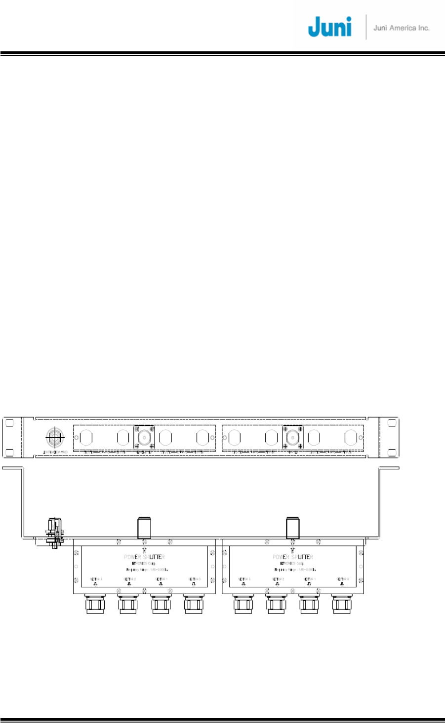
JUNI JF-46-E1900/CFN03
CDMA FIBER FED REPEATER OPERATIONS MANUAL
JUNI AMERICA PROPRIETARY & CONFIDENTIAL
Revision 0.01 Juni America Inc.
89
Appendix E. BTS Hotel Rack Installation
Procedure
The following procedure is a guide for installing JF-43B Donor Hub Unit on to the rack.
1. The 10.5 in. (6 RU) high Donor Hub Shelf (DHS) is a 19 inch rack mount unit,
supports up to 4 Remote Units and mounts to the front of a standard 19 inch rack.
2. The 1.75 in (1 RU) high 4-Way Splitter Panel supports up to 4 Remote Units and
mounts to the rear of the rack. This panel is placed above and to the rear of the
DHS. Nine RF cables are integral to the Donor RF Connector Panel assembly, and
are routed across the top of the DHS to RF connectors on the front panel of the
DHS.
3. There is no additional vertical rack space requirement for external duplexers and/or
external transmit combiners, since these functions are integral to each Donor Optic
Transceiver Module.
4. The 1RU vertical spacing provided by the 4-Way Splitter Panel facilitates airflow
above the DHS. There is no other vertical rack space requirement for airflow.
5. Therefore the total rack space height requirement (per 4 Remote Units) is 10.5 +
1.75 in. = 12.25 in. ('7RU).
6. Therefore, a total of 73.5 inches of vertical rack space is required for 6 ea. Donor
subsystems [DHS + 4-Way Splitter Panel].
7. Donor Hub Unit (Indoor Configuration) Dimensions: 19 in. rack Wide x 10.43 in.
High x. 15.7 in. Deep
8. 4-Way Splitter Panel Dimensions: 19 in. rack Wide x 1.7 in. High x 7 in. Deep.
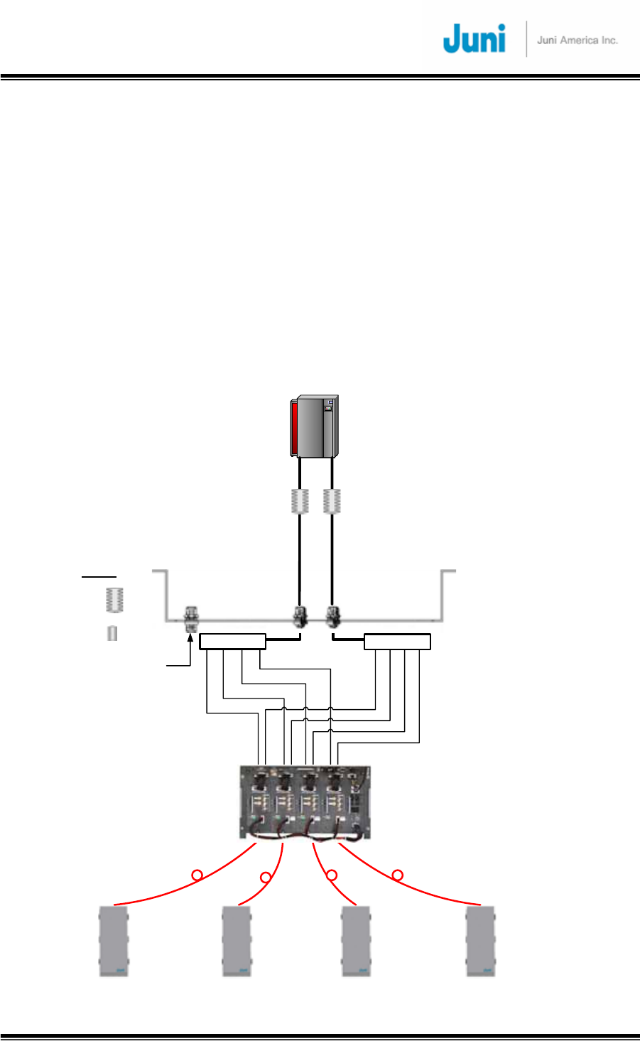
JUNI JF-46-E1900/CFN03
CDMA FIBER FED REPEATER OPERATIONS MANUAL
JUNI AMERICA PROPRIETARY & CONFIDENTIAL
Revision 0.01 Juni America Inc.
90
Appendix F. Simulcast and Non-Simulcast
Operations
The JF-46 system can be configured and operated in either Simulcast or Non-Simulcast
mode.
In Simulcast Mode, one BTS sector feeds multiple Remote Units. Juni offers a Four-Way
Splitter for use where one BTS sector feeds up to four Remote Units. It is Juni Model
JJAX0100008. The Figure below shows the Four-Way Simulcast configuration. The Four-
way Simulcast Connector Panel is intended to mount at the rear of a 19 inch EIA rack,
immediately above the associated Donor Hub Unit. RF cables are furnished which connect
from the front of the Connector Panel to the various RF connectors on the front of the Donor
Hub Unit. The RF connectors which face toward the BTS are recessed.
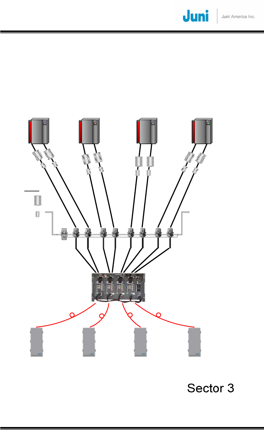
JUNI JF-46-E1900/CFN03
CDMA FIBER FED REPEATER OPERATIONS MANUAL
JUNI AMERICA PROPRIETARY & CONFIDENTIAL
Revision 0.01 Juni America Inc.
91
In Non-Simulcast mode, each Remote Unit is fed by one “dedicated BTS sector. The
advantage of this approach is higher capacity per Remote Unit, compared to Simulcast mode.
Juni offers a Non-Simulcast Connector Panel, Model Number JJAX0100006. The Non-
Simulcast Connector Panel is intended to mount at the rear of a 19 inch EIA rack,
immediately above the associated Donor Hub Unit. RF cables are furnished which connect
from the front of the Connector Panel to the various RF connectors on the front of the Donor
Hub Unit. The RF connectors which face toward the BTS are recessed.
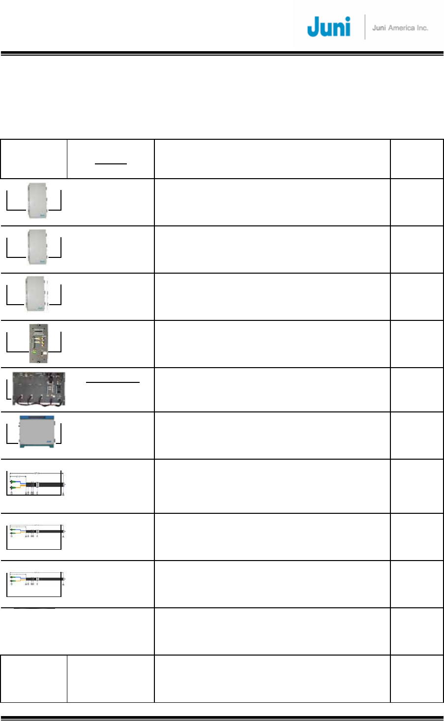
JUNI JF-46-E1900/CFN03
CDMA FIBER FED REPEATER OPERATIONS MANUAL
JUNI AMERICA PROPRIETARY & CONFIDENTIAL
Revision 0.01 Juni America Inc.
92
Appendix G. Product listing and Item
Master List
Image Name
Part Number Description Item
Master
Remote
PCS "A"
JJFE4600011
JF-46 1900 MHz (Band A) Remote Unit with 115/230 VAC
power supply, 1 ea. 0
Remote
PCS "B"
JJFE4600012
JF-46 1900 MHz (Band B) Remote Unit with 115/230 VAC
power supply, 1 ea. 0
Remote
PCS "D&E"
JJFE4600013
JF-46 1900 MHz (Band D & E) Remote Unit with 115/230 VAC
power supply, 1 ea. 0
Optic Module
for JF46
JJFE4600016
Optic Module for JF-46 Only,
(Can only be used with JF46 Donors & remotes, incompatible
with JF43/b)
0
Donor Indoor
+/- 20 to 60VDC
JJFE4600001
JF46 Indoor Donor, +/- 20 to 60VDC, w/o Optic Module 0
Donor Outdoor
115/230 VAC
JJFE4600005
JF46 Outdoor Donor, +115/230 VAC, w/o Optic Module 0
Optical Jumper
2- 200'
JJAX0100014
200 ft. External Optical Dual Fiber Jumpers (2 Jumpers), 1 ea.,
112776
Optical Jumper
1- 200'
JJAX0100015
200 ft. External Optical Fiber Single Jumper Kit (1 Jumper), 1
ea.
112777
Optical Jumper
1- 100'
JJAX0100013
100ft External Optical Fiber Jumper Kit (2
Jumpers)
101835
HUB Site Kit
DBS SITE
JJAX0100004
DBS Donor Hub Site Accessories Kit
101827
HUB Site Kit
Universal
JJAX0100005
Universal Donor Hub Site Accessories Kit
101828

JUNI JF-46-E1900/CFN03
CDMA FIBER FED REPEATER OPERATIONS MANUAL
JUNI AMERICA PROPRIETARY & CONFIDENTIAL
Revision 0.01 Juni America Inc.
93
Simulcast KIT
4-WAY
JJAX0100008
Panel Mounted 4 way Splitter & Cables
101831
Simulcast KIT
2-WAY
JJAX0100007
2-2 way Splitter & Cables
101830
Panel
Indoor
JJAX0100006
Connector Panel & Cables
101829