Inkel JR20CU RF Repeater Coverage Unit User Manual Manual
INKEL Corporation RF Repeater Coverage Unit Manual
UserManual.wiki
>
Inkel
>
JR20CU User Manual
Manual
Navigation menu
Upload a User Manual
Namespaces
Wiki Guide
HTML
PDF
Info
Views
User Manual
Discussion / Help
Navigation


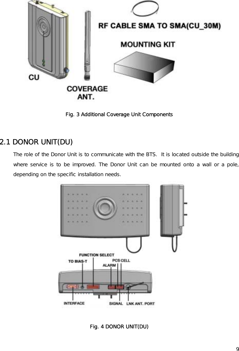
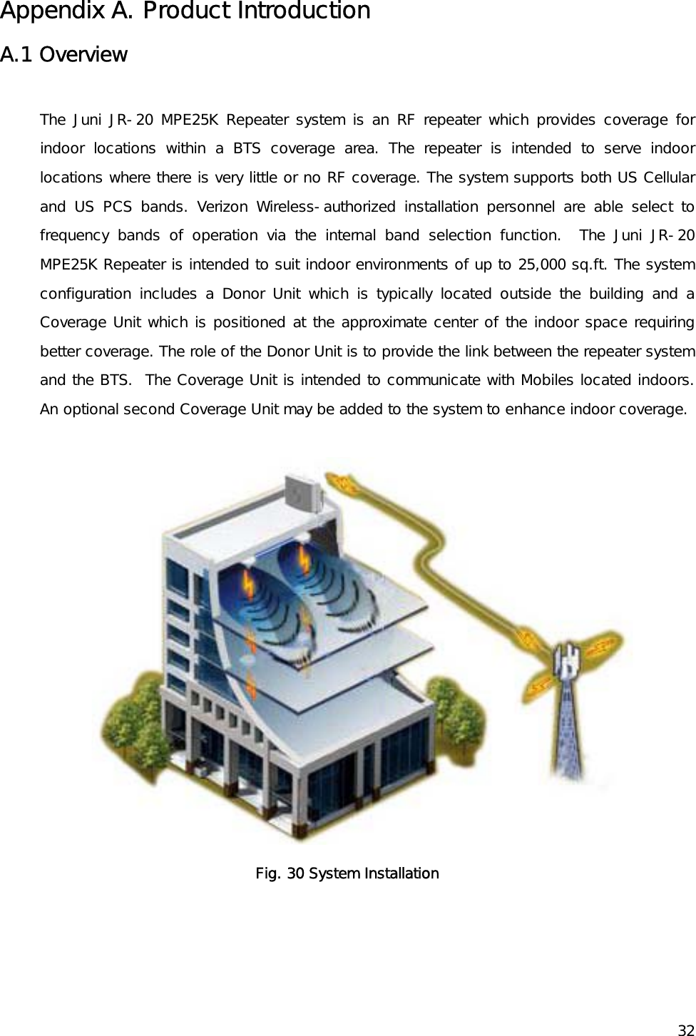
![15 5. DONOR UNIT(DU) SET Installation 5.1 BRACKET-DU Image 5.1.1. DU 에 BRACKET – DU Connection Image 1) The length unit is [mm]. Fig. 7 MTG Bracket Image 5.1.2. BRACKET-DU Connection Image to Installation(WALL or POLE) ( Pole Mounting ) ( Lumber Wall Mounting) ( Concrete Wall Mounting ) Fig. 8 MTG BRACKET Mounting (Pole, Lumber Wall, Concrete Wall) Connection Image](https://usermanual.wiki/Inkel/JR20CU/User-Guide-963574-Page-15.png)
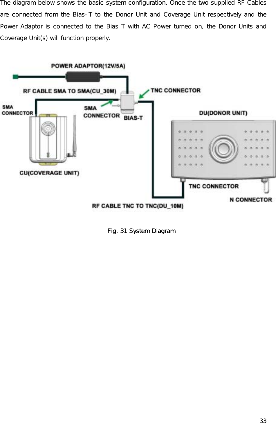
![165.2 BRACKET Connection to DU 1) 1) APPLY NUT, SPRING WASHER, PLATE WASHER. (Do not Connect Completely) [NUT, SPRING WASHER, PLATE WASHER each 4ea] 2) Apply BRACKET/MTG to DU. APPLY NUT COMPLETELY USING PROVIDED TOOL. [BRACKER/MTG 1ea] Fig. 9 DU Bracket Connection Diagram](https://usermanual.wiki/Inkel/JR20CU/User-Guide-963574-Page-16.png)
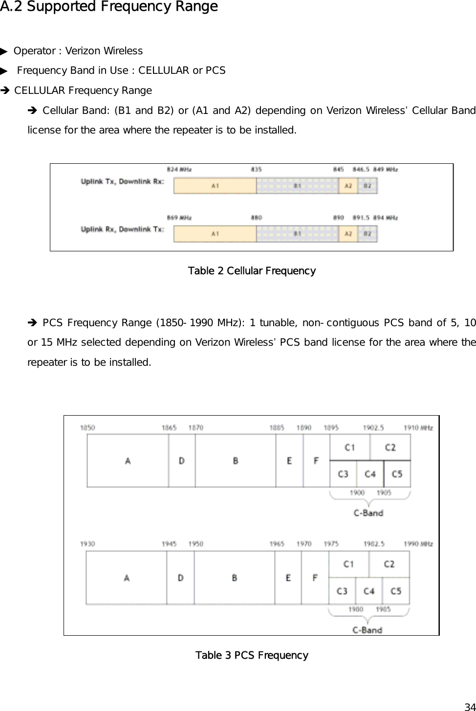
![175.3 BRACKET Connection depending on Installation Place 5.3.1. BRACKET/MTG POLE MOUNTING 1) Secure DU to the pole using U-BOLT. 2) Insert U-BOLT to between BRACKET-POLE and BRACKET-DU 3) Apply the pole to the BRACKET-DU: use the nuts and u-bolts provided to fixate the bracket into the Pole. [BRACKET-DU 1ea, BRACKET-POLE 2ea, U-Bolt 2ea, NUT, SPRING WASHER, PLATE WASHER each 4ea] Fig. 10 POLE MOUNTING MTG BRACKET-DU Connection Sequence 5.3.2. BRACKET/MTG LUMBER WALL Mounting 1) Secure BRACKET-DU to the wooden wall. Using cross driver connect SCREW to wooden wall through BRACKET-DU. [BRACKET-DU 1ea, SCREW 4ea] Fig. 11 LUMBER WALL MOUNTING MTG BRACKET-DU Connection Sequence](https://usermanual.wiki/Inkel/JR20CU/User-Guide-963574-Page-17.png)
![185.3.3. BRACKET/MTG CONCRETE WALL Mounting 1) Drill on the wall as the BRACKET-ANT distance. (forφ 10mm Hole depth to be 30 to 40 mm.) 2) INSERT SET-ANCHOR TO DRILLED HOLE. 3) Secure BRACKET-DU to the Wall and fix the nut. [BRACKER-DU 1ea, SET-ANCHOR 4ea] Fig. 12 CONCRETE WALL MOUNTING MTG BRACKET-DU Connection Sequence 5.4 DU Connection (same as 5.1) with BRACKET(same as 5.2) 1) APPLY DU to the BRACKET. 2) Apply the NUT to the upside of BRACKET like below sequence. – Do not apply the NUT](https://usermanual.wiki/Inkel/JR20CU/User-Guide-963574-Page-18.png)
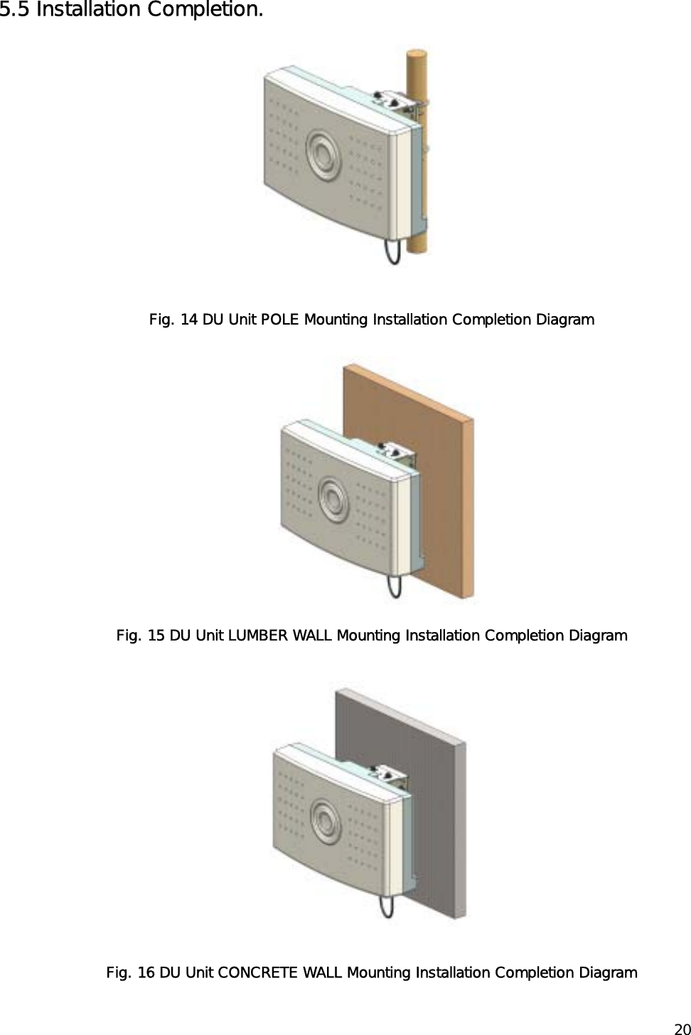
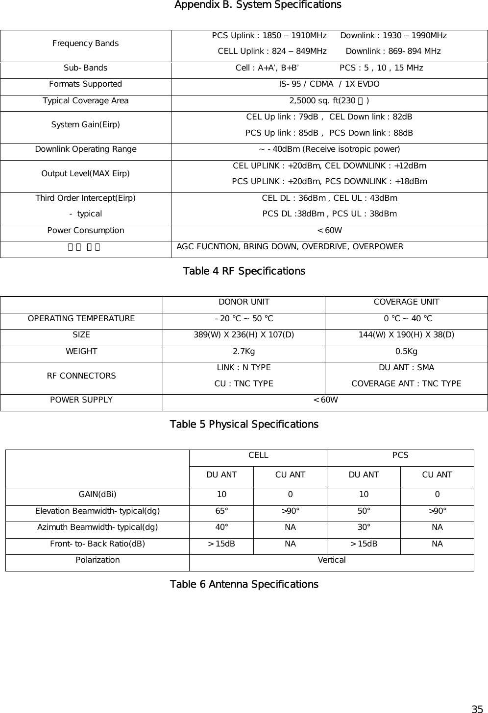
![19completely. 3) Set the receiving direction of the ANTENNA and apply the NUT completely using the provided tool. [NUT, SPRING WASHER, PLATE WASHER each 4ea] Fig. 13 DU Unit Wall Mounting](https://usermanual.wiki/Inkel/JR20CU/User-Guide-963574-Page-19.png)