INNOMEDIA TECHNOLOGY HG-W-B03-0001 Smart Speakerphone User Manual
INNOMEDIA TECHNOLOGY INC Smart Speakerphone Users Manual
UserManual.wiki
>
INNOMEDIA TECHNOLOGY
>
HG-W-B03-0001 User Manual
>
Users manual
Contents
1.
Users manual
2.
Users Manual
Users manual
Navigation menu
Upload a User Manual
Namespaces
Wiki Guide
HTML
PDF
Info
Views
User Manual
Discussion / Help
Navigation
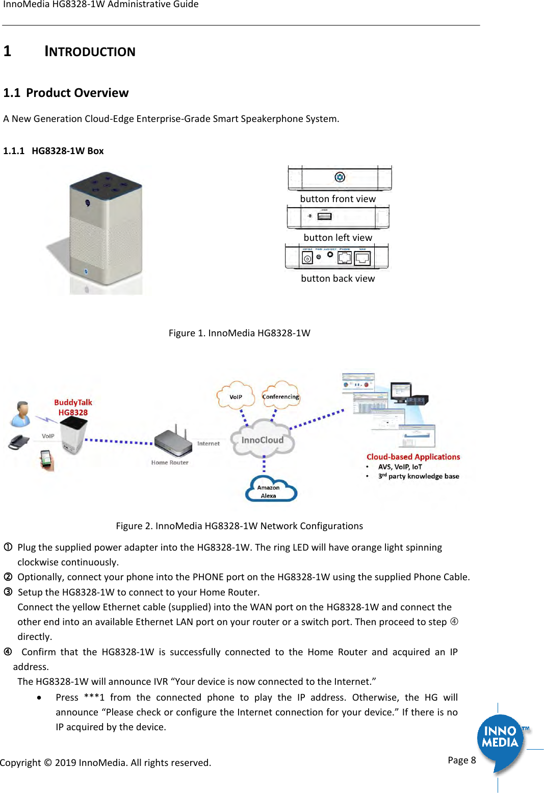
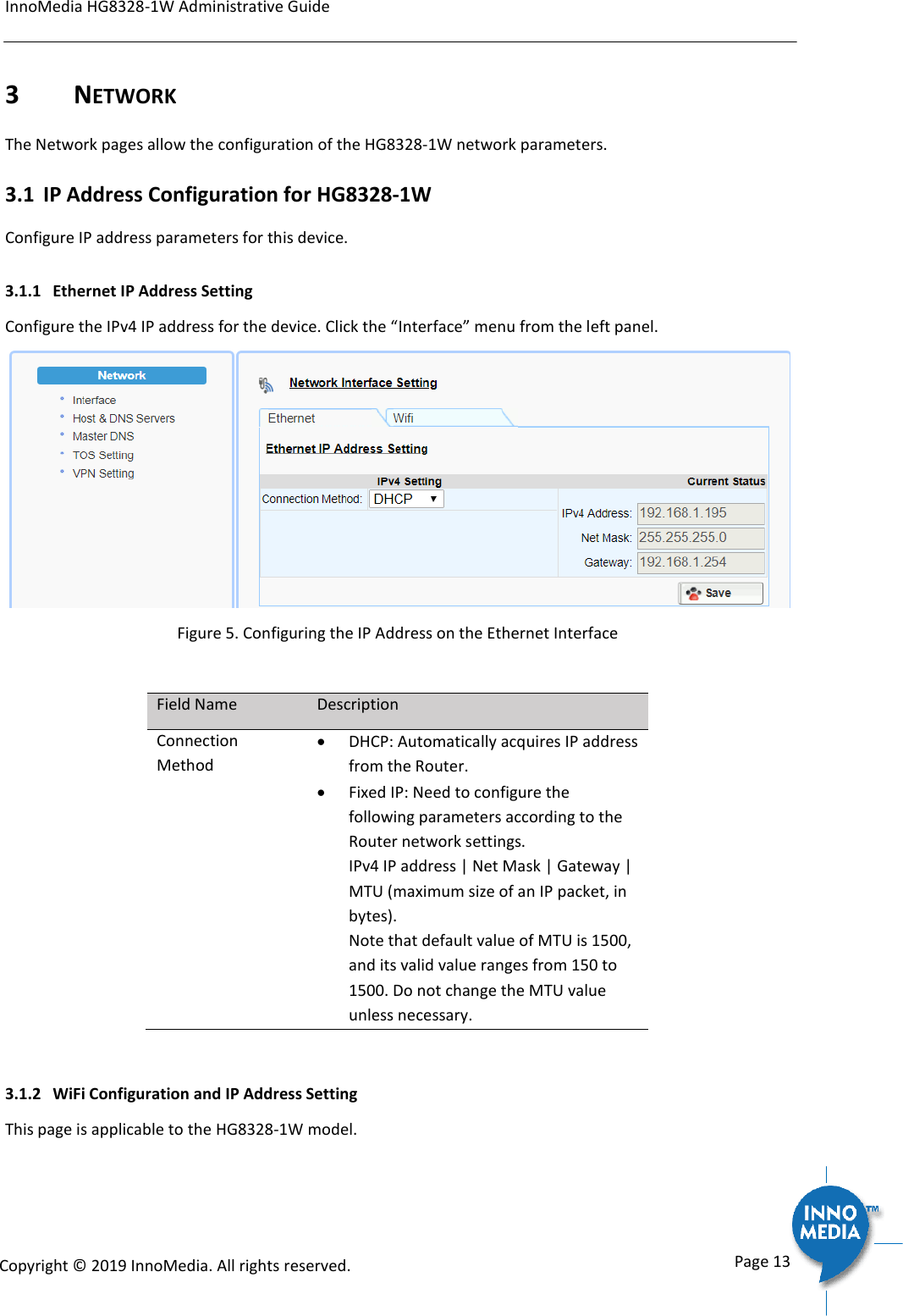
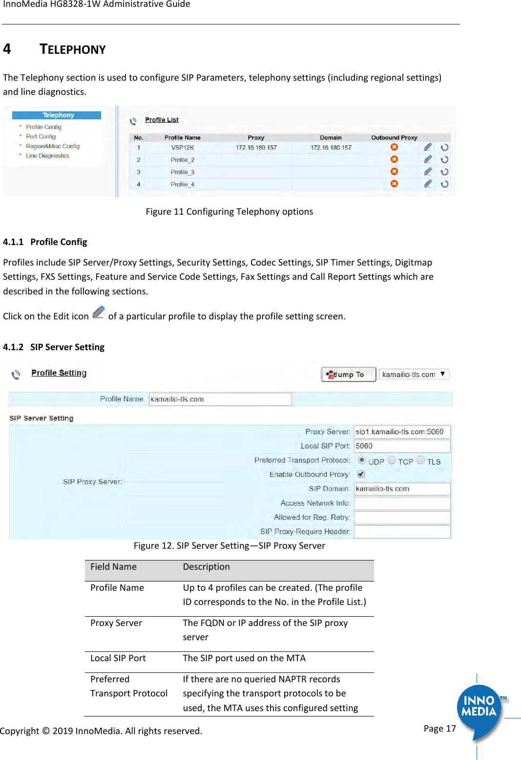
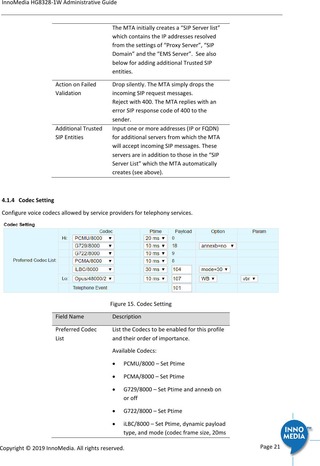
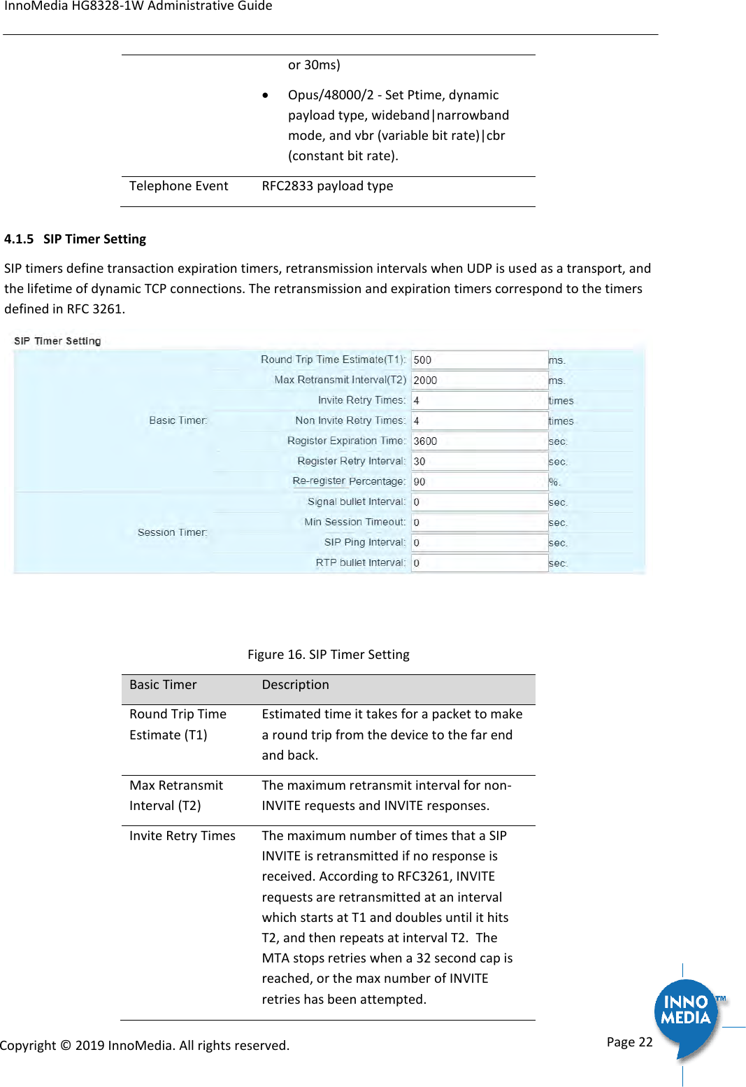
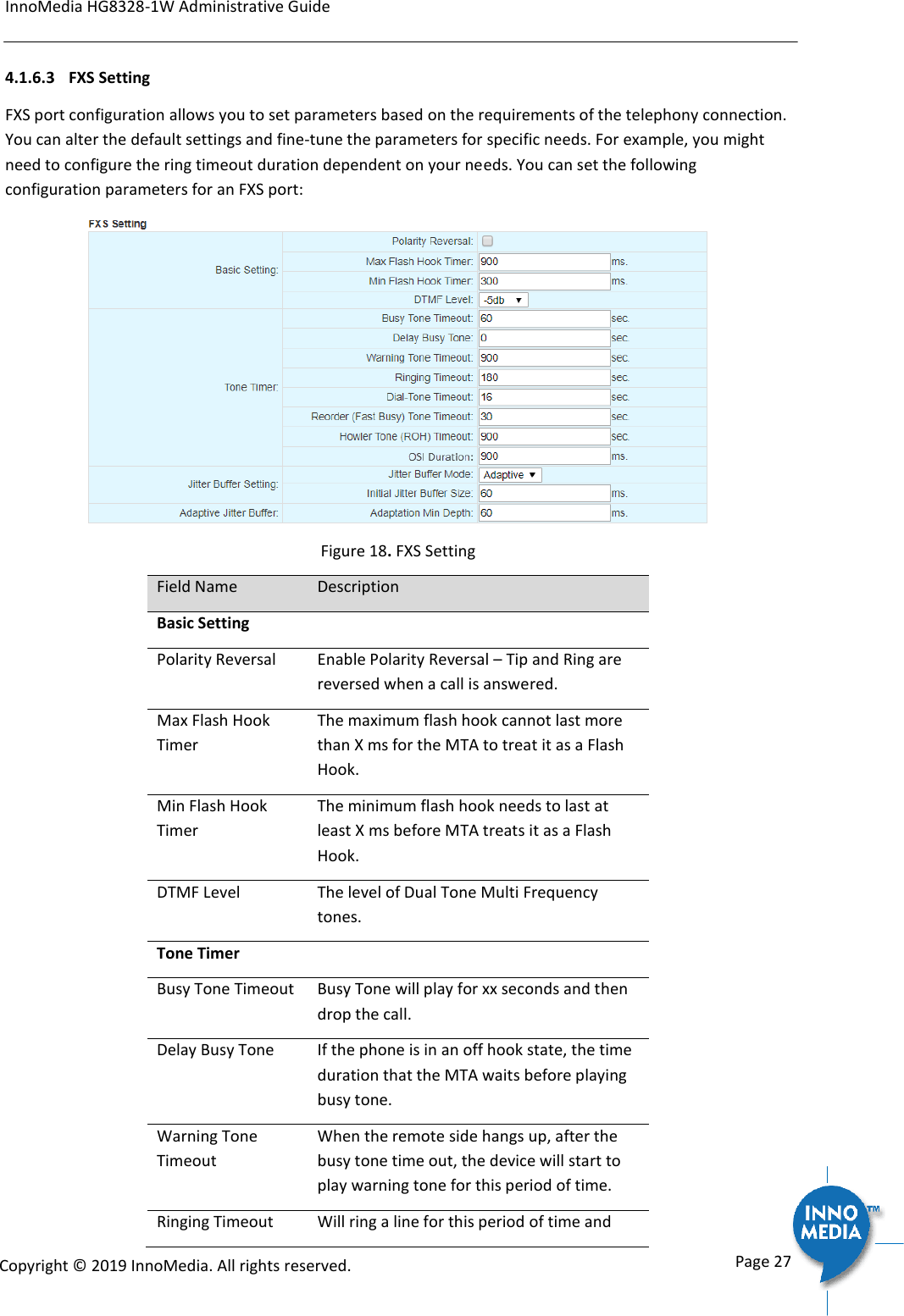
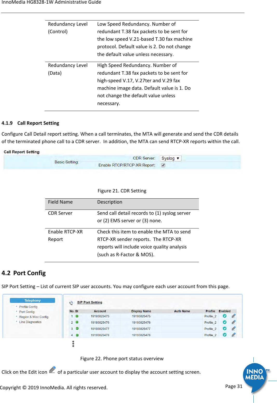
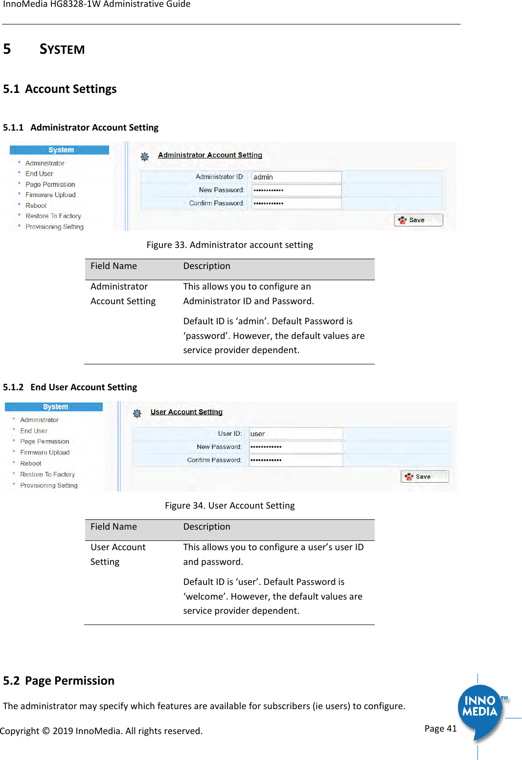
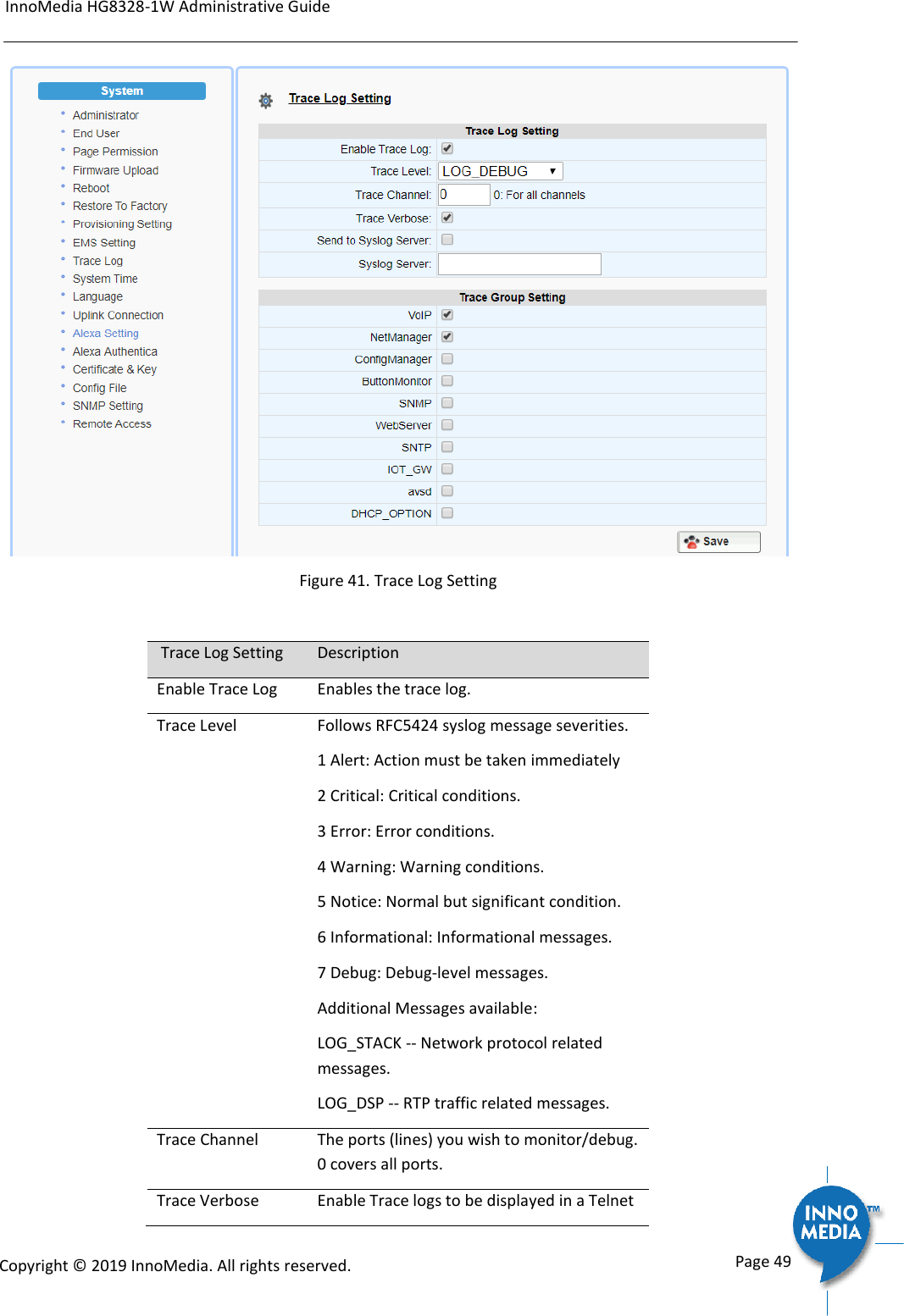
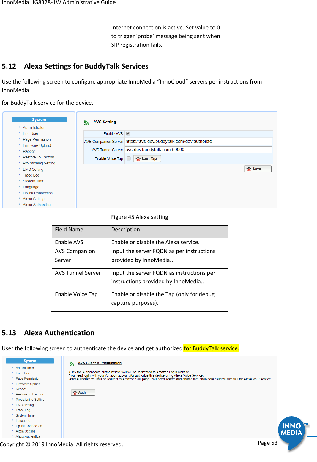
![InnoMedia HG8328-1W Administrative Guide Page 9 Copyright © 2019 InnoMedia. All rights reserved. Once the HG8328-1W connects to the voice service provider network, and completes the registration and service provision process, the phone connected to the unit will receive a dial tone and can make calls. 1.1.2 Box Control Panel Ring LED State description Ring LED State description Not lit. Idle state and Ready to take voice commands. MIC off (red) Purple. Do not disturb on. Single flash. Yellow. Notifications. Blue-Cyan. Thinking. Altering at 620 ms Speaking. Altering at 1260 ms Yellow-Red Notification queued and MIC off. Cyan. Listening. Orange. Spinning clockwise. While connecting to the Internet during initialization. Fading blinking. Fail to connect to Internet, or system error. icon State description icon State description Phone. Not-lit. Ready to take command. Tap to make a call. Phone. Green. [Ongoing call|Ringing] mode. No voice mail. Phone. Yellow. Voice mails and registered. Phone. Red [BuddyTalk not setup|DND|Not registered] mode Unmute. Not lit. Tap to mute. Mute. Red. [BuddyTalk not setup|Mute] mode. Tap to unmute. Flash key. Not lit. Tap to merge calls, transfer a call, call waiting … Flash. Green for being tapped. Buddytalk not setup. Red. Volume down. Not lit. Tap to lower volume When speaker is muted. Red. Volume up. Not Lit. Tap to increase volume When speaker is muted. Red. MIC. Not lit. Unmute. Tap to mute. MIC mute. Red. Tap to unmute. Press for 3 seconds. Cyan. [Listening|Speaking] mode. Tap to stop.](https://usermanual.wiki/INNOMEDIA-TECHNOLOGY/HG-W-B03-0001.Users-manual/User-Guide-4191726-Page-9.png)
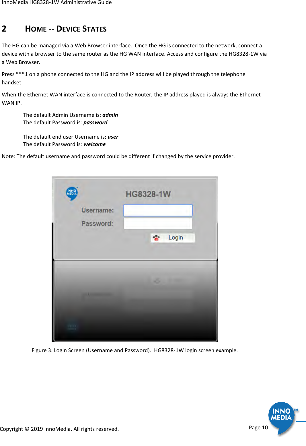
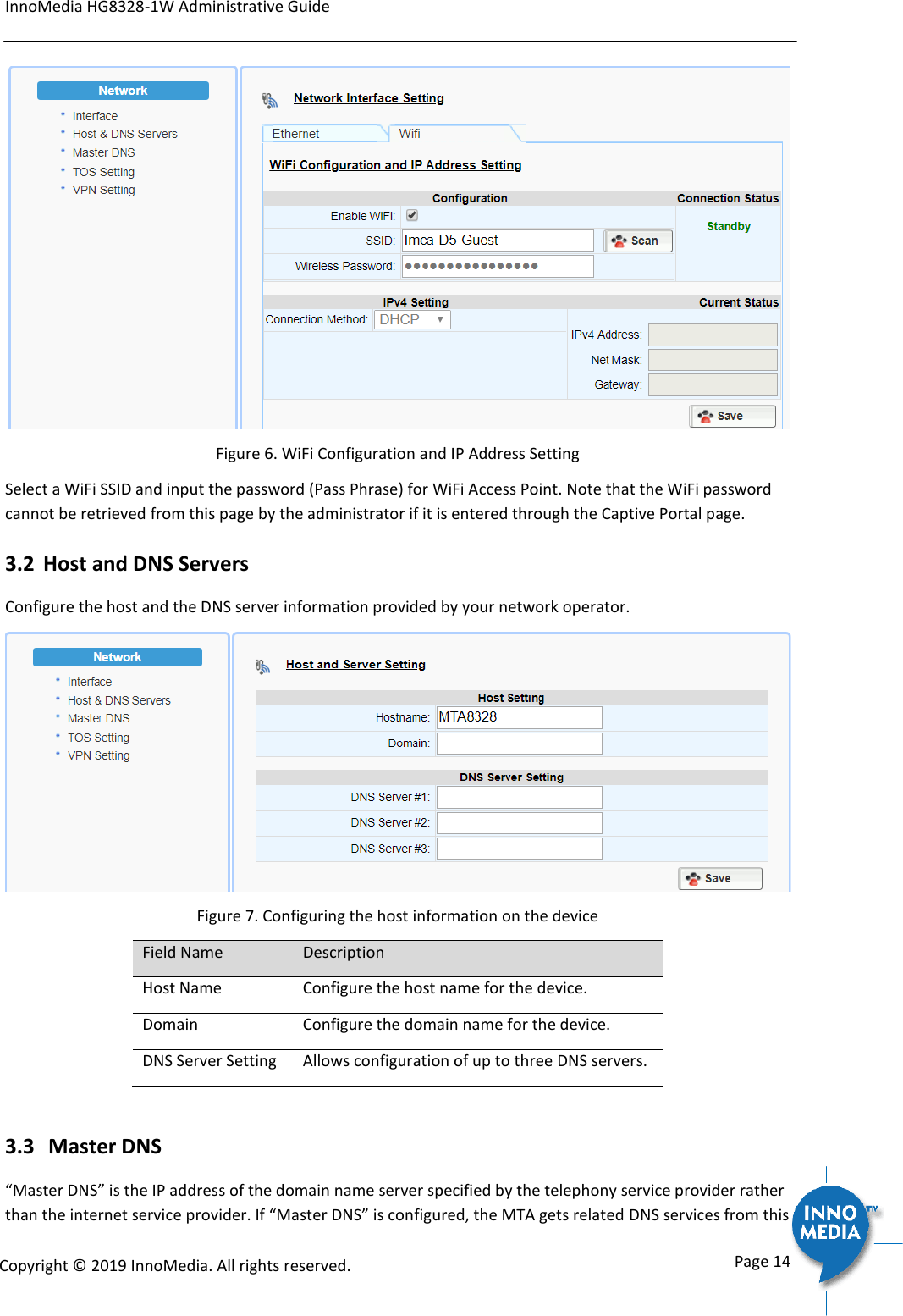
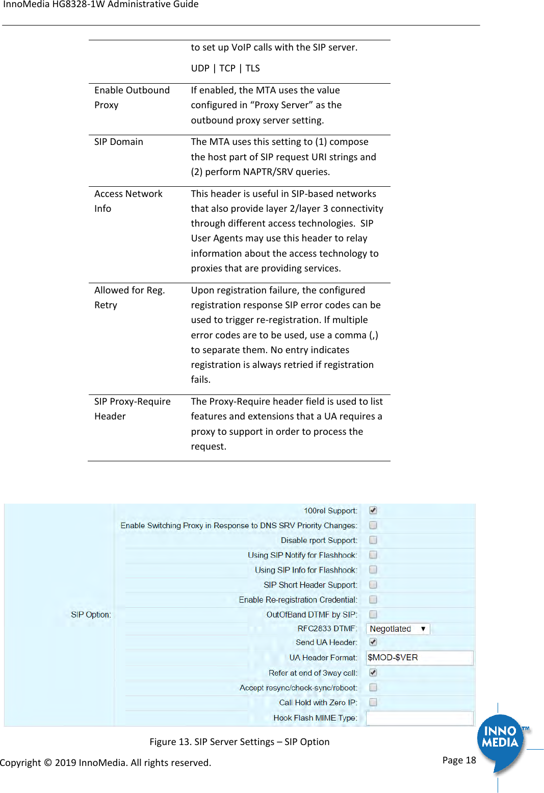
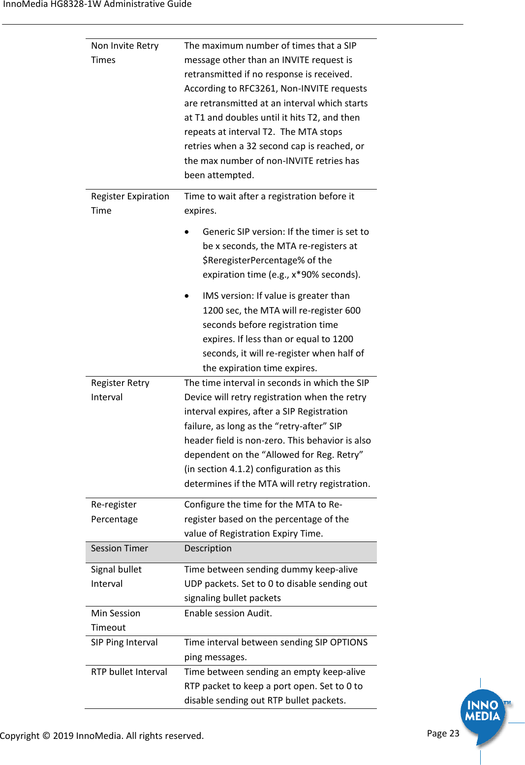

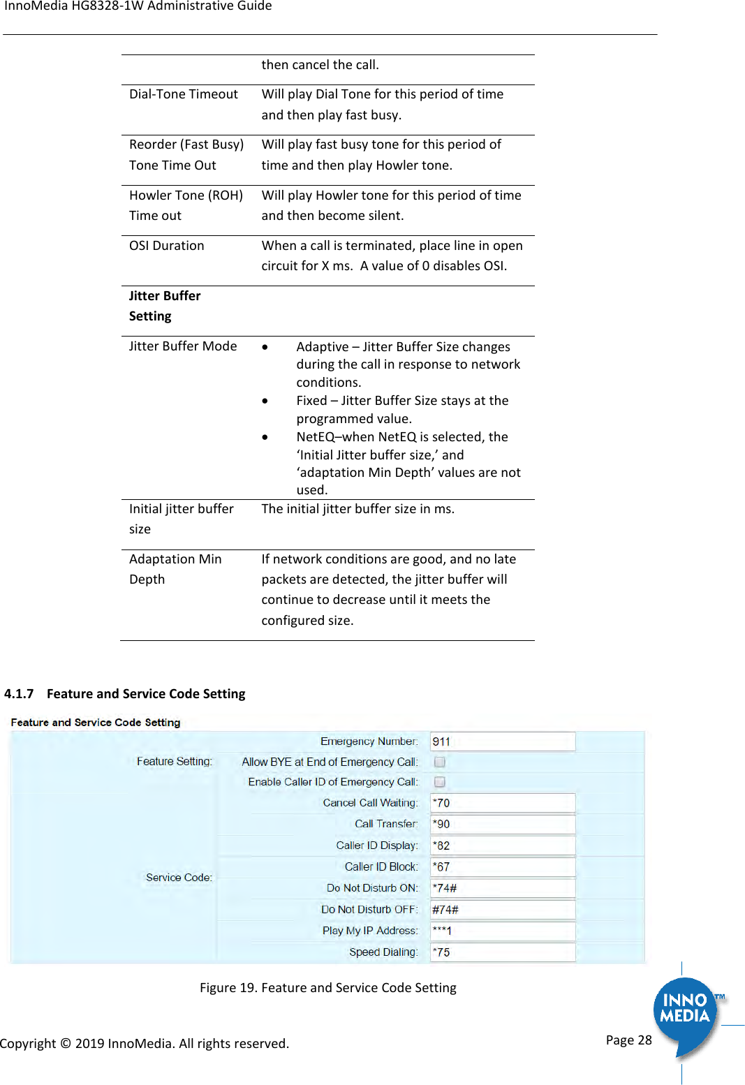
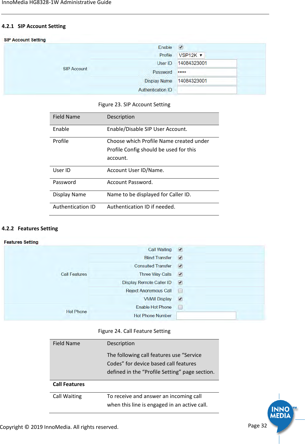
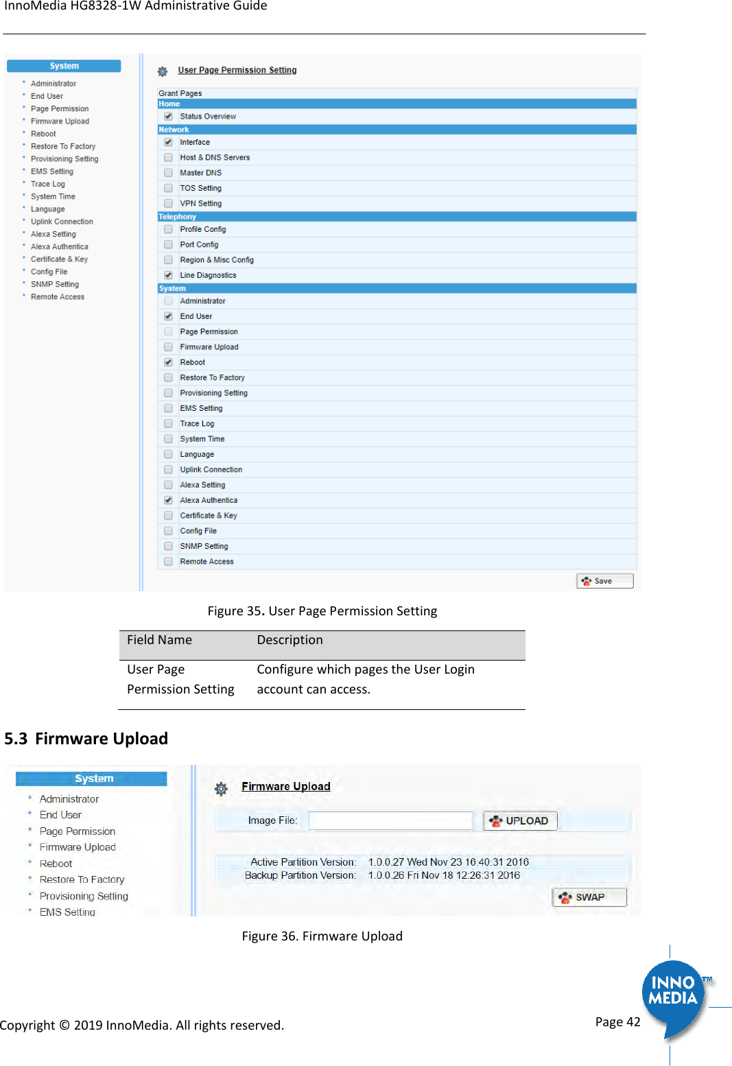
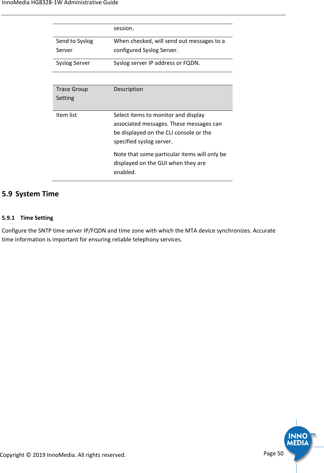
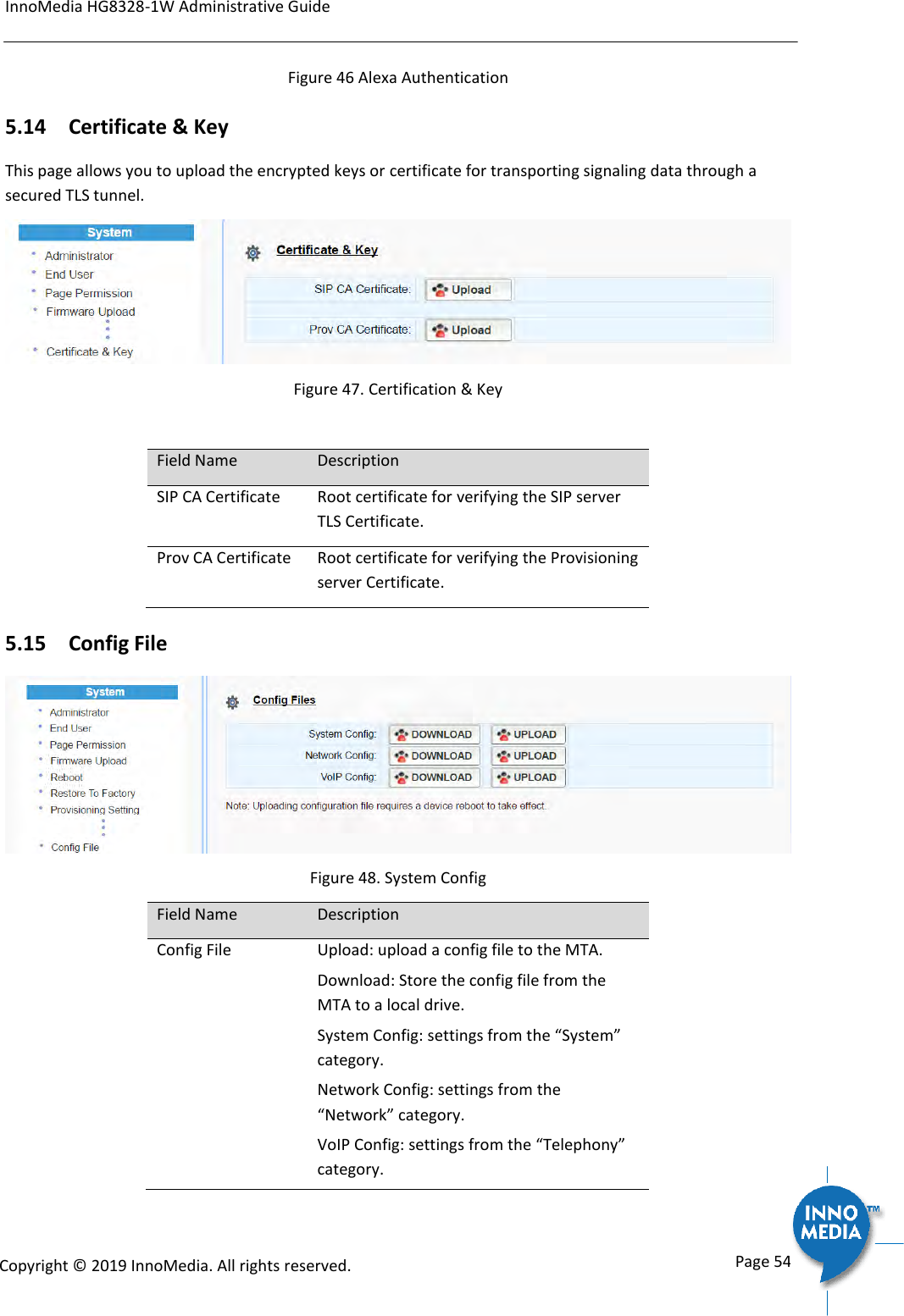
![InnoMedia HG8328-1W Administrative Guide Page 26 Copyright © 2019 InnoMedia. All rights reserved. 4.1.6.1 A Digitmap Example 0 Local operator 00 Long distance operator [1-7]xxx Local extension number 8xxxxxxx Local number #xxxxxxx Shortcut to local number at other corporate sites [0-9*].# Any dialed numbers followed by a “#” sign *xx Star services 91xxxxxxxxxx Long distance number 9011 + up to 15 digits International number The dial plan described above results in the following digit map: (0| 00|[1-7]xxx|8xxxxxxx|#xxxxxxx|*xx|91xxxxxxxxxx|9011x.T|[0-9*].#) 4.1.6.2 Digitmap syntax A DigitMap, according to this syntax, is defined either by a (case insensitive) “String” or by a “list of strings” over which the SIP Device will attempt to find a shortest possible match. Regardless of the above syntax, a timer is currently only allowed if it appears in the last position in a string. Each string in the list is an alternate numbering scheme. The formal syntax of the digit map is described by the following notation: Digit ::= “0” | “1” | “2” | “3” | “4” | “5” | “6” | “7” | “8” | “9” Timer ::= “T” | “t” -- matches the detection of a timer Letter ::= Digit | Timer | “#” | “*” | “A” | “a” | “B” | “b” | “C” | “c” | “D” | “d” Range ::= “X” | “x” -- matches any single digit | “[“ Letters “]” -- matches any of the specified letters Letters ::= Subrange | Subrange Letters Subrange ::= Letter -- matches the specified letter | Digit “-” Digit -- matches any digit between first and last Position ::= Letter | Range StringElement ::= Position -- matches an occurrence of the position | Position “.” -- matches an arbitrary number of occurrences of the position, including 0 String ::= StringElement | StringElement String StringList ::= String | String “|” StringList DigitMap ::= String | “(“ StringList “)"](https://usermanual.wiki/INNOMEDIA-TECHNOLOGY/HG-W-B03-0001.Users-manual/User-Guide-4191726-Page-26.png)
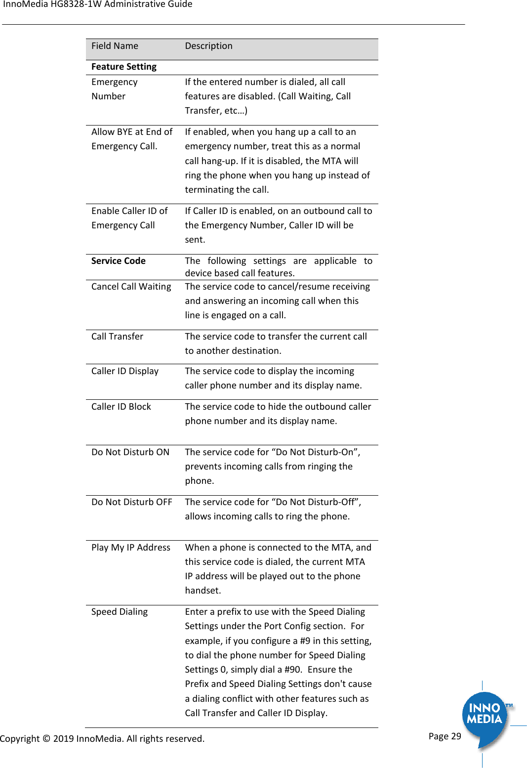
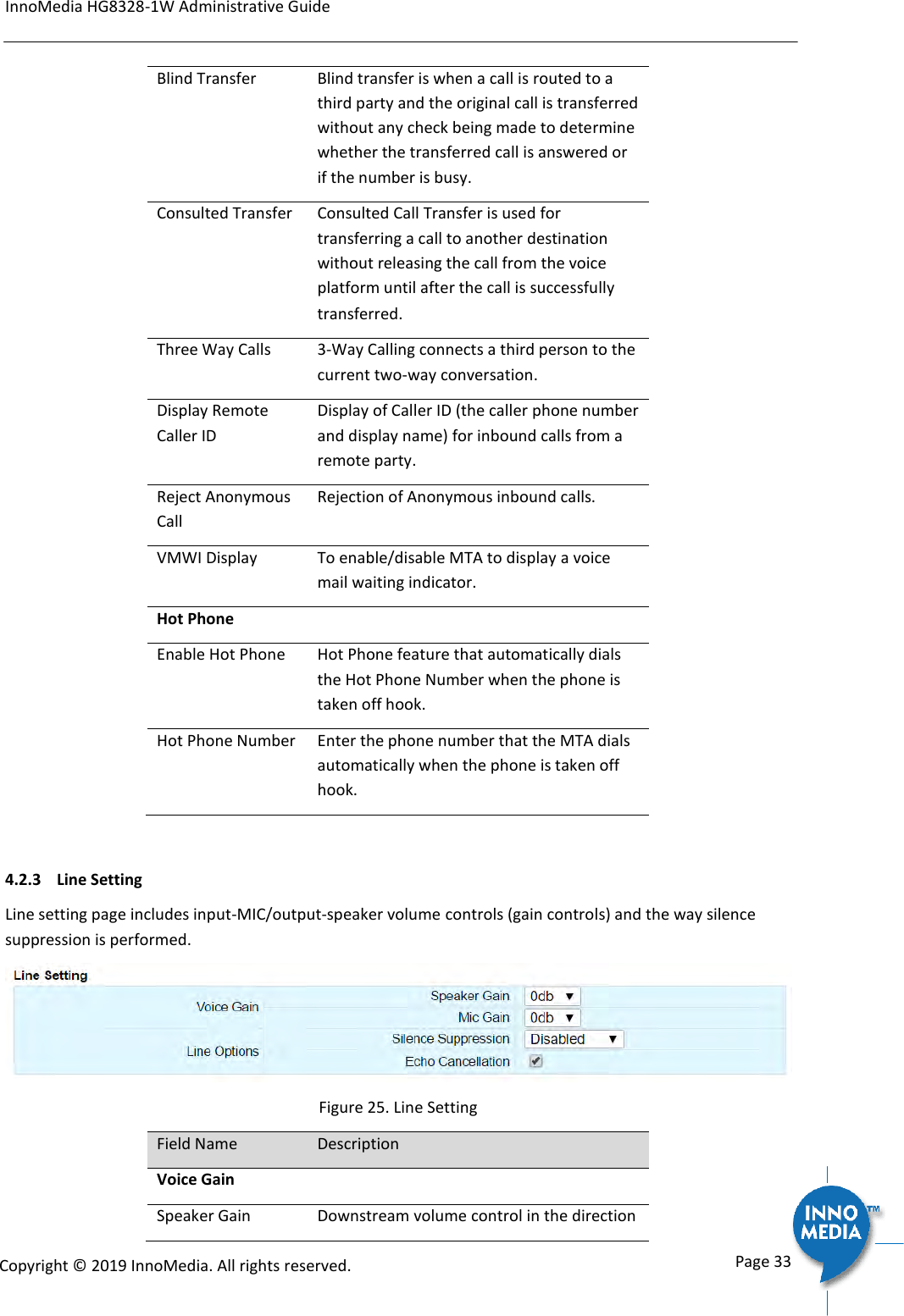
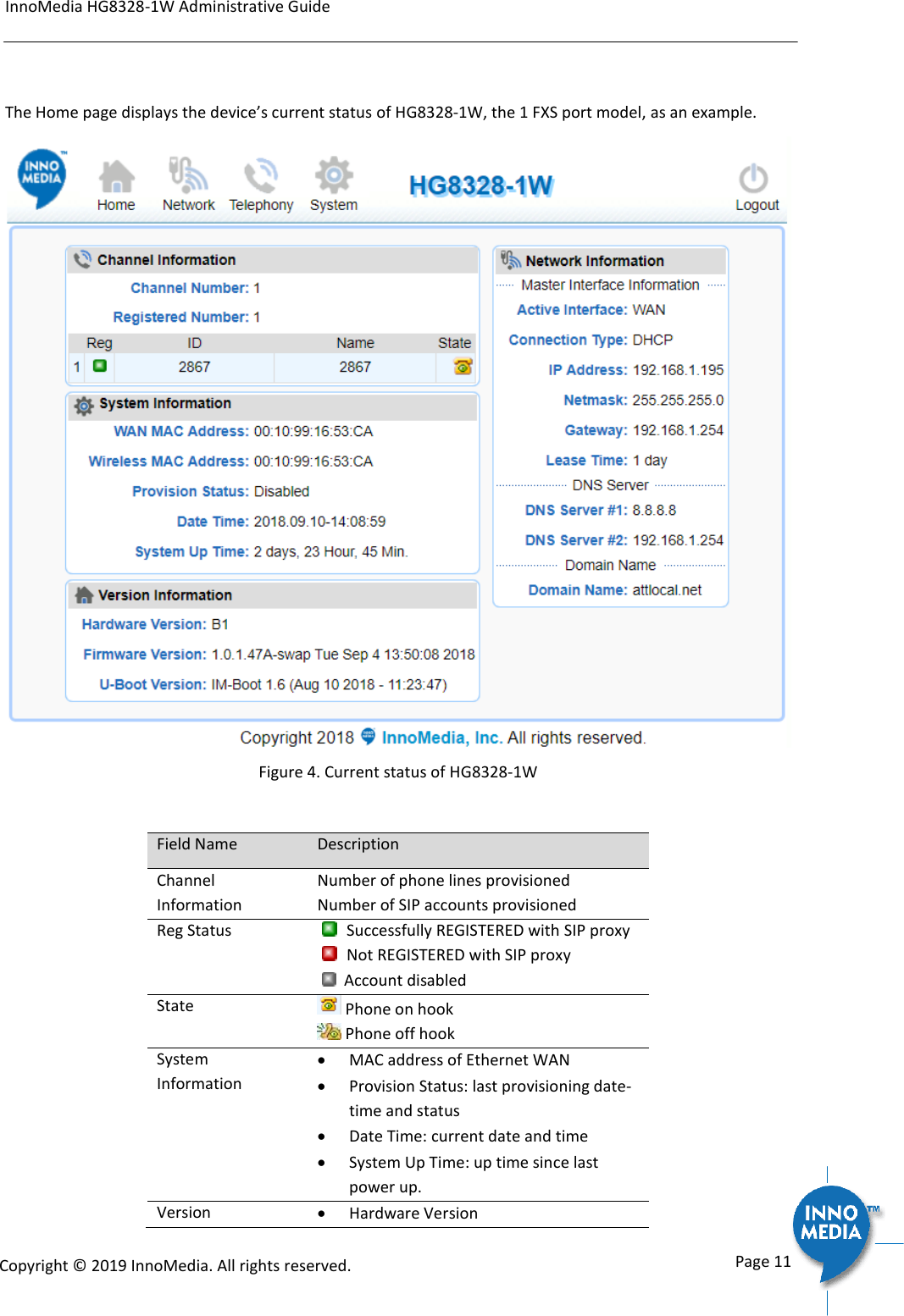
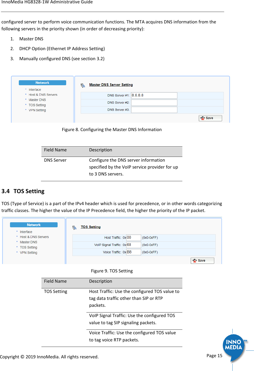
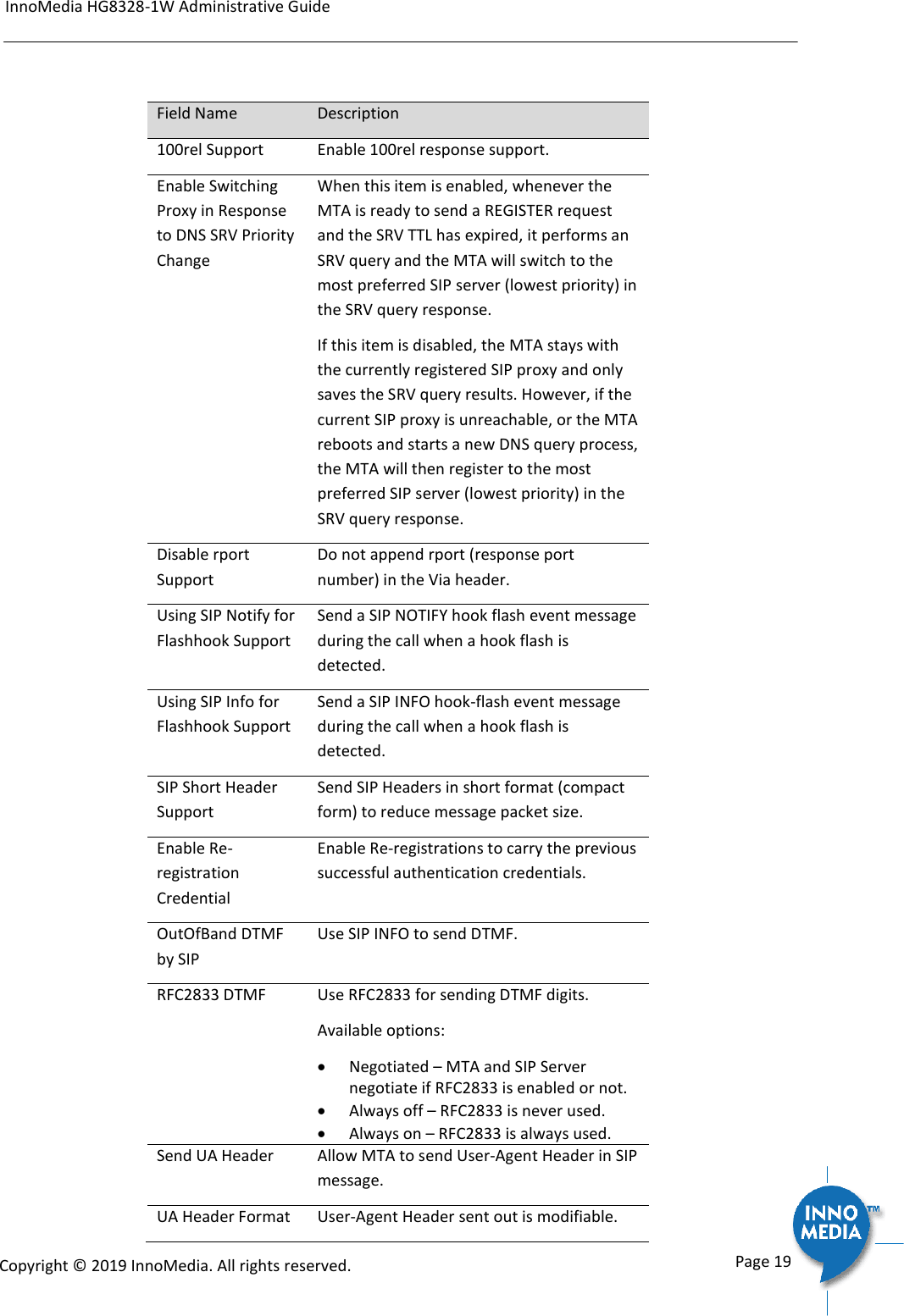
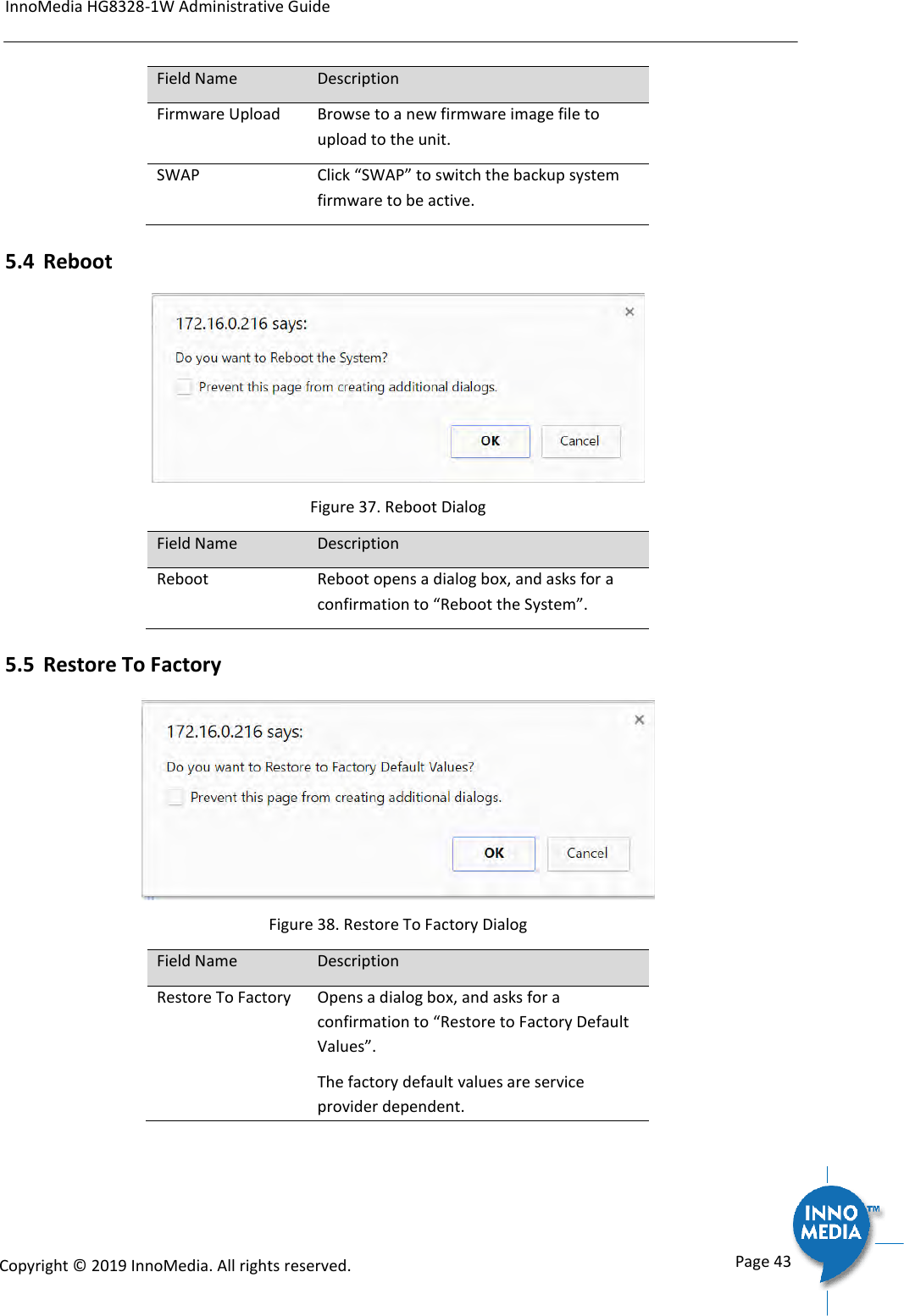
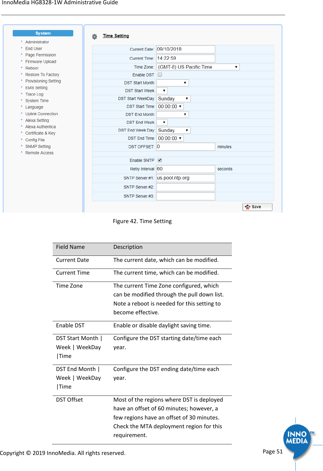
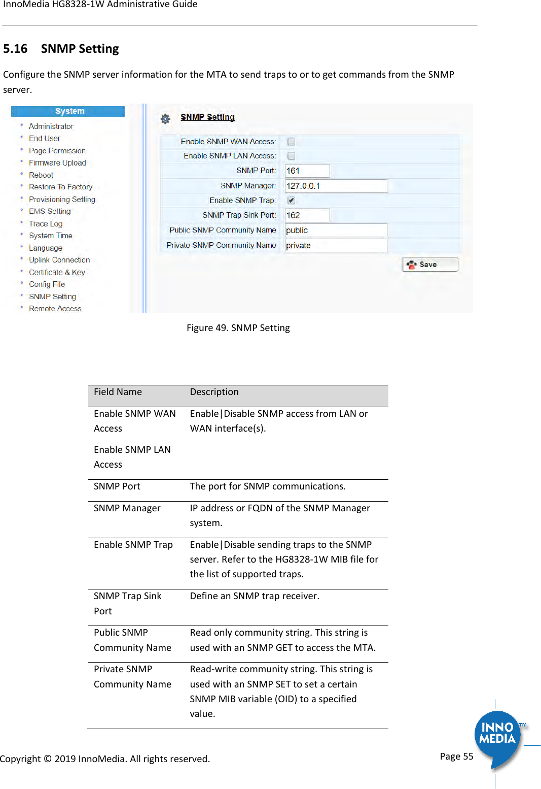
![InnoMedia HG8328-1W Administrative Guide Page 37 Copyright © 2019 InnoMedia. All rights reserved. Figure 30. Tone Cadence Setting Tone Cadence Setting Format – freq1, freq2,vol,+[on1,off1,on2,off2,…] frequency 1, frequency 2, volume level in dBm + : loop the tone(s) forever [ on1 duration in ms, off1 duration in ms…]. If the duration value is 65535, keep playing the last tone. Field Name Description Dial Tone A dial tone indicates that the MTA is ready to accept calls. Busy Tone A busy signal indicates a failure to complete the requested call. Reasons could be: The called number is occupied, or The other party has hung up at the end of a call. Ringback Tone A ring back tone (or ringing tone) is heard by the caller while the phone they are calling is being rung. Reorder Tone Reorder tone, also known as fast busy tone, is the congestion tone or all trunks busy tone of a PSTN network. It varies from country to country. Stutter Tone A "stuttered" or interrupted dial tone is often used to indicate a Calling feature such as Call forwarding has been activated. (The voice mail waiting tone is represented by](https://usermanual.wiki/INNOMEDIA-TECHNOLOGY/HG-W-B03-0001.Users-manual/User-Guide-4191726-Page-37.png)
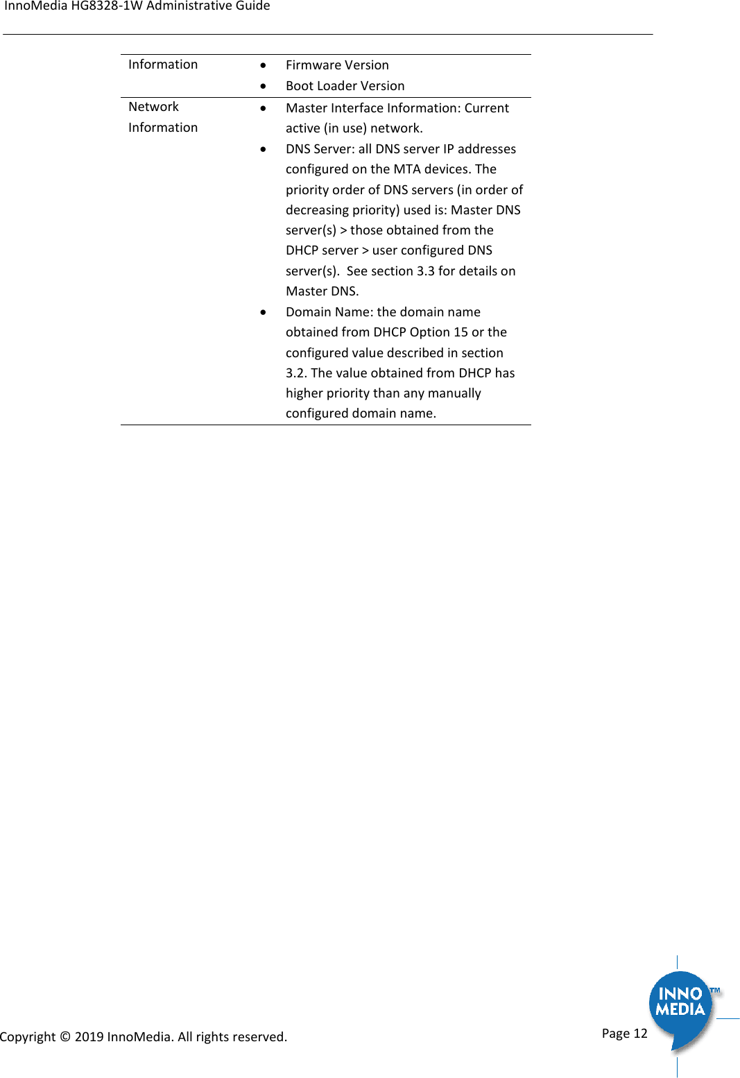
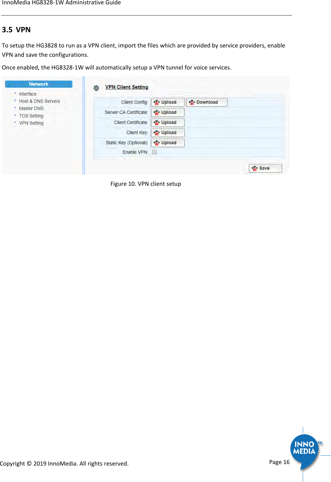
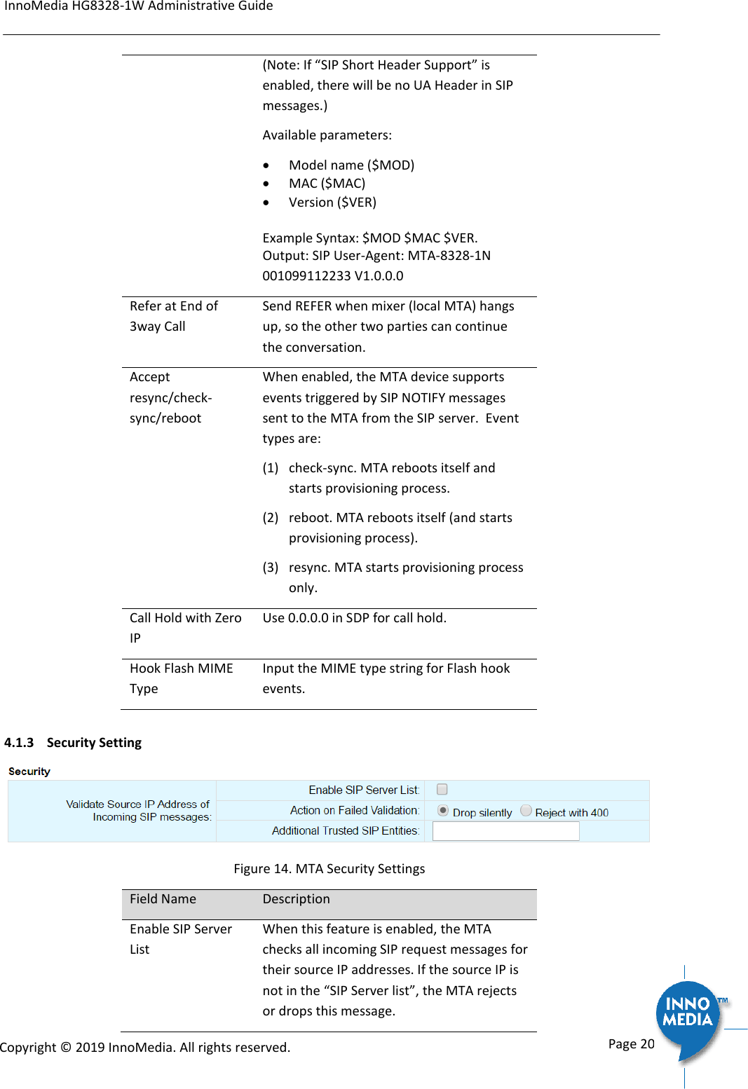
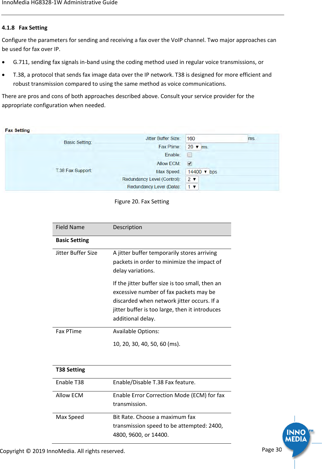
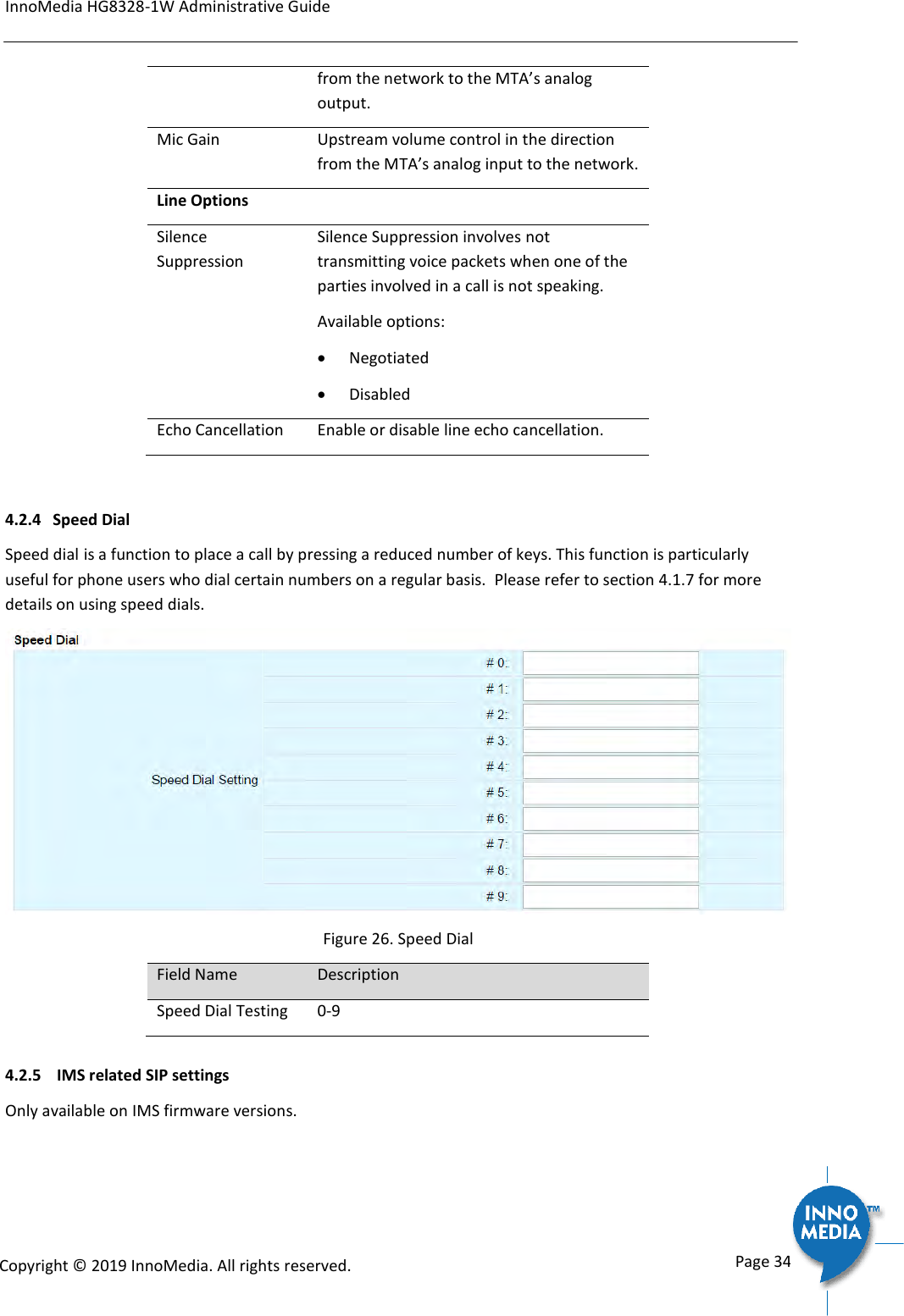
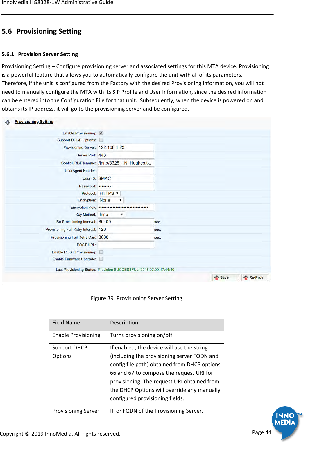
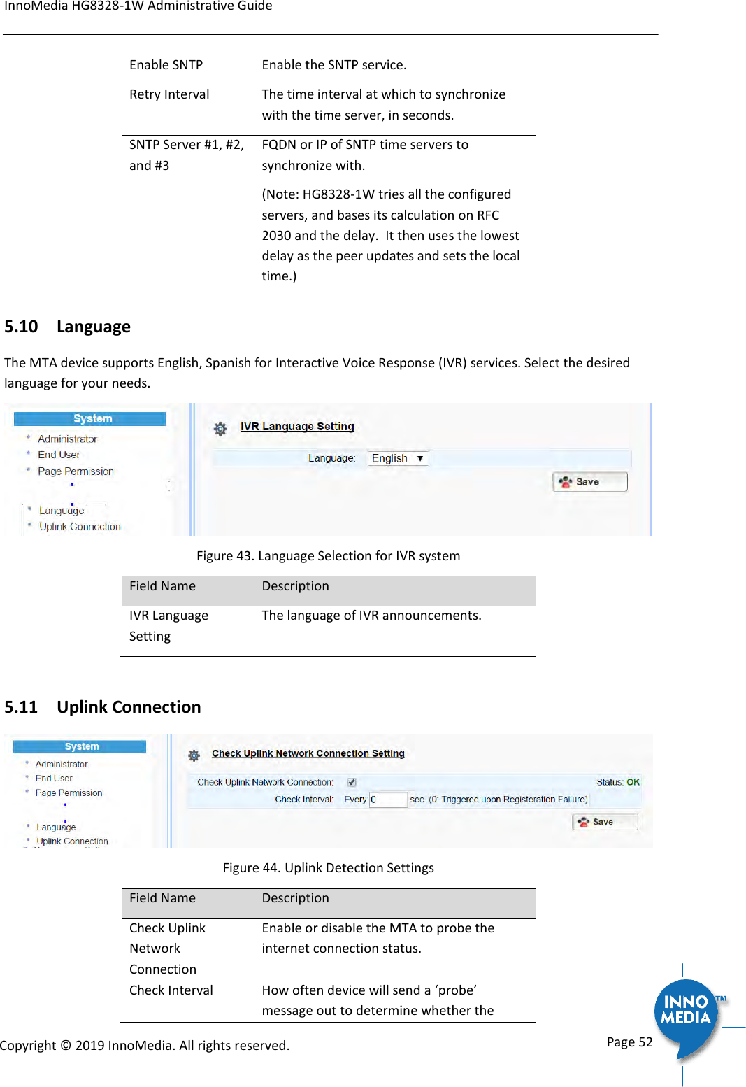
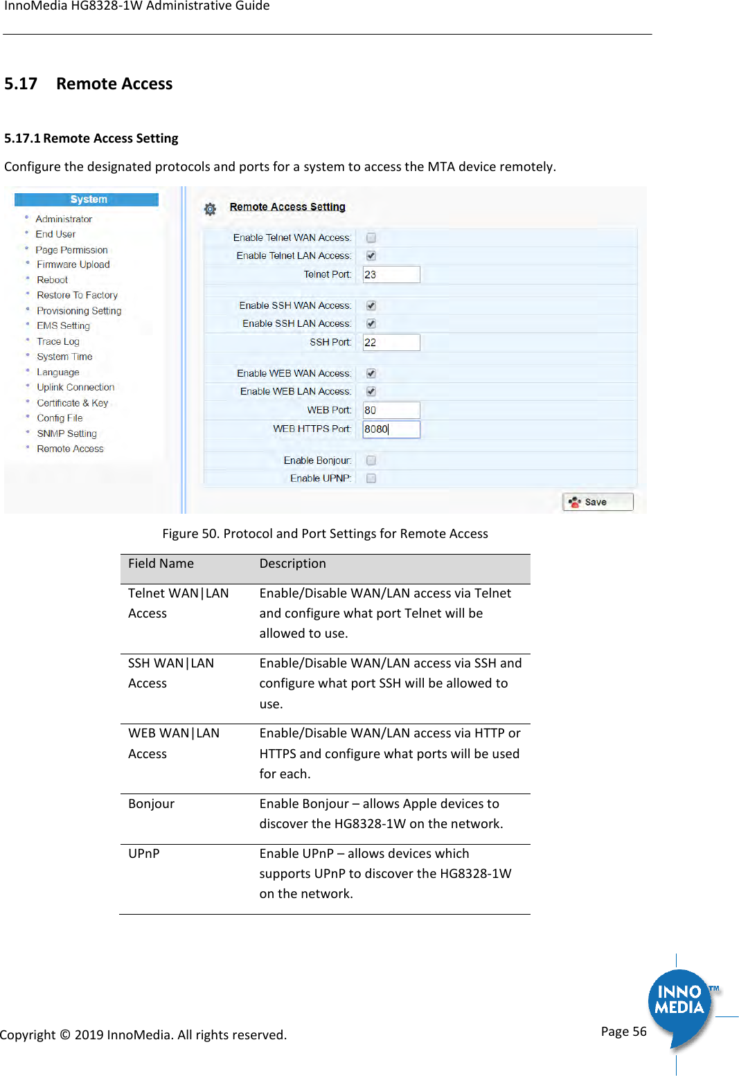
![InnoMedia HG8328-1W Administrative Guide Page 38 Copyright © 2019 InnoMedia. All rights reserved. VMWI Tone below.) VMWI Tone Voice Mail Waiting Indication, indicating that voice mail is waiting. Confirmation Tone Confirmation Tone is used to acknowledge receipt for special services, such as: Speed dialing, dial number has been recorded. Call forwarding activation and de-activation, etc. Call Waiting Tone 1-4 Call waiting tones are used for call waiting conditions. Howler (ROH) Tone Receiver off hook tone 4.3.4 Ring Cadence Setting For a telephone receiving an incoming call, ring cadence settings control the timing of the incoming ring-signal. This varies from country to country and may consist, for instance, of the ring voltage being applied for two seconds, followed by four seconds off, then back on for two seconds, and so on, until the phone is answered or the calling party hangs up, or a maximum number of rings is reached. Note that HG8328-1W supports multiple ring cadence profiles for different countries. When shipped from the factory, the MTA’s ring cadence is set to match country requirements. You can manually set the ring cadence if you wish to override the default country values. Ring Cadence Setting (Format +[on1,off1,on2,off2,…]) + : loop the tone(s) forever [ on1 duration in ms, off1 duration in ms…]. If the duration value is 65535, keep playing the last tone. Figure 31. Ring Cadence Setting Field Name Description Default Ring Cadence For a telephone receiving an incoming call, the default timing pattern of the incoming](https://usermanual.wiki/INNOMEDIA-TECHNOLOGY/HG-W-B03-0001.Users-manual/User-Guide-4191726-Page-38.png)
![InnoMedia HG8328-1W Administrative Guide Page 57 Copyright © 2019 InnoMedia. All rights reserved. 6 CLI COMMAND REFERENCES Only the Administrator user is allowed to access the HG CLI console. The login ID and password are identical to those for WEB console login. The CLI command hierarchy is designed similarly to that of the WEB console. Once logged in successfully, the command menu is displayed. [v]voip VoIP Configuration [n]net Network Configuration [s]system System [f]factory Factory [d]restore Restore to Default Setting Type the char enclosed in the square bracket [] to enter that particular section. Type question mark “?” at any level to display available commands. Type “cd ..” to go back to the upper level. [f] factory sub-menu is password protected. Type command “save” or “write” whenever the MTA configurations being updated through CLI commands. Under any level, to show debug messages on the CLI console, type “debug on”; to stop debug messages being displayed, simply type “debug off”.](https://usermanual.wiki/INNOMEDIA-TECHNOLOGY/HG-W-B03-0001.Users-manual/User-Guide-4191726-Page-57.png)
![InnoMedia HG8328-1W Administrative Guide Page 58 Copyright © 2019 InnoMedia. All rights reserved. Appendix A The use of encryption key methods Inno rc4_102 Use utility “rc4_102” to encrypt the plaintext config file (e.g., MTA6328_$MAC.cfg) with a 32-char-long key. Syntax: rc4_102 mac key input-file ['out-prefix'] [logfile] Example: rc4_102 001099001122 1234567890qwertyuiop1234567890as MTA_sample_config.txt MTA Output: Encrypted config file: MTA001099001122.cfg is created. Openssl command example Provisioning config file should be encrypted using the following command at the provisioning server when AES-256 is selected from the encryption menu. $ openssl enc –aes-256-cbc –k password –in infile –out outfile](https://usermanual.wiki/INNOMEDIA-TECHNOLOGY/HG-W-B03-0001.Users-manual/User-Guide-4191726-Page-58.png)