INNOMEDIA TECHNOLOGY HG-W-B03-0001 Smart Speakerphone User Manual
INNOMEDIA TECHNOLOGY INC Smart Speakerphone Users Manual
Contents
- 1. Users manual
- 2. Users Manual
Users manual

January, 2019
InnoMedia HG8328-1W
Administrative Guide
INNOMEDIA CONFIDENTIAL
This document contains proprietary information of InnoMedia Inc., and its receipt or possession does not
convey any rights to reproduce, disclose its contents, or to manufacture, use or sell anything it may describe.
It may not be reproduced, disclosed or used without specific written authorization of InnoMedia Inc.

InnoMedia HG8328-1W Administrative Guide
Page 2
Copyright © 2019 InnoMedia. All rights reserved.
Federal Communication Commission Interference Statement
The HG8328-1W series of products have been tested and found to comply with the limits for a Class B digital
device, pursuant to Part 15 of the FCC Rules. These limits are designed to provide reasonable protection
against harmful interference in a residential installation. This equipment generates, uses and can radiate
radio frequency energy and, if not installed and used in accordance with the instructions, may cause harmful
interference to radio communications. However, there is no guarantee that interference will not occur in a
particular installation. If this equipment does cause harmful interference to radio or television reception,
which can be determined by turning the equipment off and on, the user is encouraged to try to correct the
interference using one of the following measures:
● Reorient or relocate the receiving antenna.
● Increase the separation between the equipment and receiver.
● Connect the equipment into an outlet on a circuit different from that to which the receiver is connected.
● Consult the dealer or an experienced radio/TV technician for help.
FCC Caution: Any changes or modifications not expressly approved by the party responsible for compliance
could void the user’s authority to operate this equipment.
This device complies with Part 15 of the FCC Rules. Operation is subject to
the following two conditions: (1) This device may not cause harmful
interference, and (2) this device must accept any interference received,
including interference that may cause undesired operation.
IMPORTANT NOTE:
FCC Radiation Exposure Statement:
This equipment complies with FCC radiation exposure limits set forth for an uncontrolled environment. This
equipment should be installed and operated with a minimum distance of 20cm between the radiator & your
body.

InnoMedia HG8328-1W Administrative Guide
Page 3
Copyright © 2019 InnoMedia. All rights reserved.
Table of Contents
1 Introduction ................................................................................................................................................... 8
1.1 Product Overview ................................................................................................................................... 8
1.1.1 HG8328-1W Box ........................................................................................................................... 8
1.1.2 Box Control Panel ......................................................................................................................... 9
2 Home -- Device States .................................................................................................................................. 10
3 Network ....................................................................................................................................................... 13
3.1 IP Address Configuration for HG8328-1W ............................................................................................ 13
3.1.1 Ethernet IP Address Setting ........................................................................................................ 13
3.1.2 WiFi Configuration and IP Address Setting ................................................................................. 13
3.2 Host and DNS Servers ........................................................................................................................... 14
3.3 Master DNS .......................................................................................................................................... 14
3.4 TOS Setting ........................................................................................................................................... 15
3.5 VPN ....................................................................................................................................................... 16
4 Telephony .................................................................................................................................................... 17
4.1.1 Profile Config .............................................................................................................................. 17
4.1.2 SIP Server Setting ........................................................................................................................ 17
4.1.3 Security Setting ........................................................................................................................... 20
4.1.4 Codec Setting .............................................................................................................................. 21
4.1.5 SIP Timer Setting ......................................................................................................................... 22
4.1.6 DigitMap Setting ......................................................................................................................... 24
4.1.7 Feature and Service Code Setting ............................................................................................... 28
4.1.8 Fax Setting .................................................................................................................................. 30
4.1.9 Call Report Setting ...................................................................................................................... 31
4.2 Port Config ............................................................................................................................................ 31
4.2.1 SIP Account Setting ..................................................................................................................... 32
4.2.2 Features Setting .......................................................................................................................... 32
4.2.3 Line Setting ................................................................................................................................. 33
4.2.4 Speed Dial ................................................................................................................................... 34
4.2.5 IMS related SIP settings .............................................................................................................. 34
4.3 Telephony Region and Misc Setting ..................................................................................................... 35
4.3.1 Media Port Setting ...................................................................................................................... 35
4.3.2 Regional Setting .......................................................................................................................... 36
4.3.3 Tone Cadence Setting ................................................................................................................. 36
4.3.4 Ring Cadence Setting .................................................................................................................. 38
4.4 Line Diagnostics .................................................................................................................................... 39
4.4.1 GR909 Tests: triggered from the WEB Administrative Console .................................................. 39
4.4.2 GR909 Tests: triggered from SIP NOTIFY Message ..................................................................... 40
5 System .......................................................................................................................................................... 41
5.1 Account Settings ................................................................................................................................... 41
5.1.1 Administrator Account Setting ................................................................................................... 41
5.1.2 End User Account Setting ........................................................................................................... 41
5.2 Page Permission ................................................................................................................................... 41

InnoMedia HG8328-1W Administrative Guide
Page 4
Copyright © 2019 InnoMedia. All rights reserved.
5.3 Firmware Upload .................................................................................................................................. 42
5.4 Reboot .................................................................................................................................................. 43
5.5 Restore To Factory ............................................................................................................................... 43
5.6 Provisioning Setting .............................................................................................................................. 44
5.6.1 Provision Server Setting .............................................................................................................. 44
Openssl – the open source toolkit. This method can be applied when either RC4 or AES256 is selected from
the Encryption menu. Provisioning file should be encrypted using Openssl. ...................................................... 45
5.7 EMS Setting .......................................................................................................................................... 46
5.7.1 EMS Server .................................................................................................................................. 46
5.8 Trace Log .............................................................................................................................................. 48
5.8.1 Trace Log Setting......................................................................................................................... 48
5.9 System Time ......................................................................................................................................... 50
5.9.1 Time Setting ................................................................................................................................ 50
5.10 Language .............................................................................................................................................. 52
5.11 Uplink Connection ................................................................................................................................ 52
5.12 Alexa Settings for BuddyTalk Services .................................................................................................. 53
5.13 Alexa Authentication ............................................................................................................................ 53
5.14 Certificate & Key ................................................................................................................................... 54
5.15 Config File ............................................................................................................................................. 54
5.16 SNMP Setting ........................................................................................................................................ 55
5.17 Remote Access ..................................................................................................................................... 56
5.17.1 Remote Access Setting ................................................................................................................ 56
6 CLI Command references ............................................................................................................................. 57
Appendix A The use of encryption key methods ......................................................................................... 58
Appendix B InnoMedia Contact ................................................................................................................... 59

InnoMedia HG8328-1W Administrative Guide
Page 5
Copyright © 2019 InnoMedia. All rights reserved.
Table of Figures
Figure 1. InnoMedia HG8328-1W ......................................................................................................................... 8
Figure 2. InnoMedia HG8328-1W Network Configurations ................................................................................. 8
Figure 3. Login Screen (Username and Password). HG8328-1W login screen example. ................................... 10
Figure 4. Current status of HG8328-1W ............................................................................................................. 11
Figure 5. Configuring the IP Address on the Ethernet Interface ......................................................................... 13
Figure 6. WiFi Configuration and IP Address Setting .......................................................................................... 14
Figure 7. Configuring the host information on the device ................................................................................. 14
Figure 8. Configuring the Master DNS Information ............................................................................................ 15
Figure 9. TOS Setting .......................................................................................................................................... 15
Figure 10. VPN client setup................................................................................................................................. 16
Figure 11 Configuring Telephony options ........................................................................................................... 17
Figure 12. SIP Server Setting—SIP Proxy Server ................................................................................................. 17
Figure 13. SIP Server Settings – SIP Option ......................................................................................................... 18
Figure 14. MTA Security Settings ........................................................................................................................ 20
Figure 15. Codec Setting ..................................................................................................................................... 21
Figure 16. SIP Timer Setting ................................................................................................................................ 22
Figure 17. Digitmap Setting ................................................................................................................................ 24
Figure 18. FXS Setting ......................................................................................................................................... 27
Figure 19. Feature and Service Code Setting ...................................................................................................... 28
Figure 20. Fax Setting ......................................................................................................................................... 30
Figure 21. CDR Setting ........................................................................................................................................ 31
Figure 22. Phone port status overview ............................................................................................................... 31
Figure 23. SIP Account Setting ............................................................................................................................ 32
Figure 24. Call Feature Setting ............................................................................................................................ 32
Figure 25. Line Setting ........................................................................................................................................ 33
Figure 26. Speed Dial .......................................................................................................................................... 34
Figure 27. IMS Settings ....................................................................................................................................... 35
Figure 28. Media Port Setting ............................................................................................................................. 35
Figure 29. Regional settings for power and analog line specifications ............................................................... 36
Figure 30. Tone Cadence Setting ........................................................................................................................ 37
Figure 31. Ring Cadence Setting ......................................................................................................................... 38
Figure 32. GR909 Test Line Test ......................................................................................................................... 39

InnoMedia HG8328-1W Administrative Guide
Page 6
Copyright © 2019 InnoMedia. All rights reserved.
Figure 33. Administrator account setting ........................................................................................................... 41
Figure 34. User Account Setting ......................................................................................................................... 41
Figure 35. User Page Permission Setting ............................................................................................................ 42
Figure 36. Firmware Upload ............................................................................................................................... 42
Figure 37. Reboot Dialog .................................................................................................................................... 43
Figure 38. Restore To Factory Dialog .................................................................................................................. 43
Figure 39. Provisioning Server Setting ................................................................................................................ 44
Figure 40. Configuring EMS Server Information ................................................................................................. 47
Figure 41. Trace Log Setting ............................................................................................................................... 49
Figure 42. Time Setting ....................................................................................................................................... 51
Figure 43. Language Selection for IVR system .................................................................................................... 52
Figure 44. Uplink Detection Settings .................................................................................................................. 52
Figure 45 Alexa setting ....................................................................................................................................... 53
Figure 46 Alexa Authentication .......................................................................................................................... 54
Figure 47. Certification & Key ............................................................................................................................. 54
Figure 48. System Config .................................................................................................................................... 54
Figure 49. SNMP Setting ..................................................................................................................................... 55
Figure 50. Protocol and Port Settings for Remote Access .................................................................................. 56

InnoMedia HG8328-1W Administrative Guide
Page 7
Copyright © 2019 InnoMedia. All rights reserved.
About This Document
This document provides details of the features available on the InnoMedia HG8328-1W as well as feature
descriptions and the configurations required.
Revision History
Date
Version
Notes
September 10, 2018
1.0
creation
InnoMedia HG8328-1W Administrative Guide
Page 8
Copyright © 2019 InnoMedia. All rights reserved.
1 INTRODUCTION
1.1 Product Overview
A New Generation Cloud-Edge Enterprise-Grade Smart Speakerphone System.
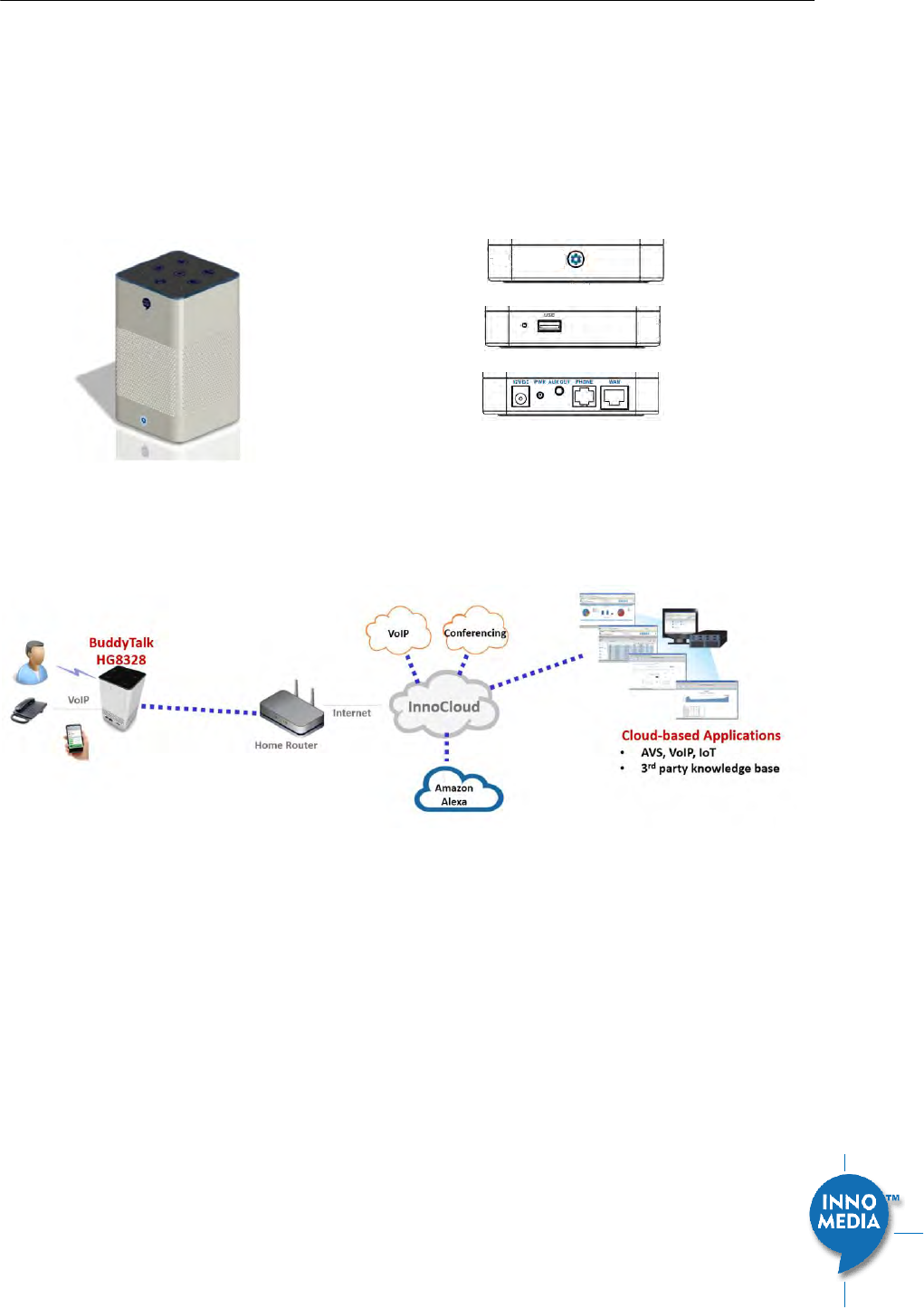
1.1.1 HG8328-1W Box
button front view
button left view
button back view
Figure 1. InnoMedia HG8328-1W
Figure 2. InnoMedia HG8328-1W Network Configurations
Plug the supplied power adapter into the HG8328-1W. The ring LED will have orange light spinning
clockwise continuously.
Optionally, connect your phone into the PHONE port on the HG8328-1W using the supplied Phone Cable.
Setup the HG8328-1W to connect to your Home Router.
Connect the yellow Ethernet cable (supplied) into the WAN port on the HG8328-1W and connect the
other end into an available Ethernet LAN port on your router or a switch port. Then proceed to step
directly.
Confirm that the HG8328-1W is successfully connected to the Home Router and acquired an IP
address.
The HG8328-1W will announce IVR “Your device is now connected to the Internet.”
Press ***1 from the connected phone to play the IP address. Otherwise, the HG will
announce “Please check or configure the Internet connection for your device.” If there is no
IP acquired by the device.
InnoMedia HG8328-1W Administrative Guide
Page 9
Copyright © 2019 InnoMedia. All rights reserved.
Once the HG8328-1W connects to the voice service provider network, and completes the registration and
service provision process, the phone connected to the unit will receive a dial tone and can make calls.
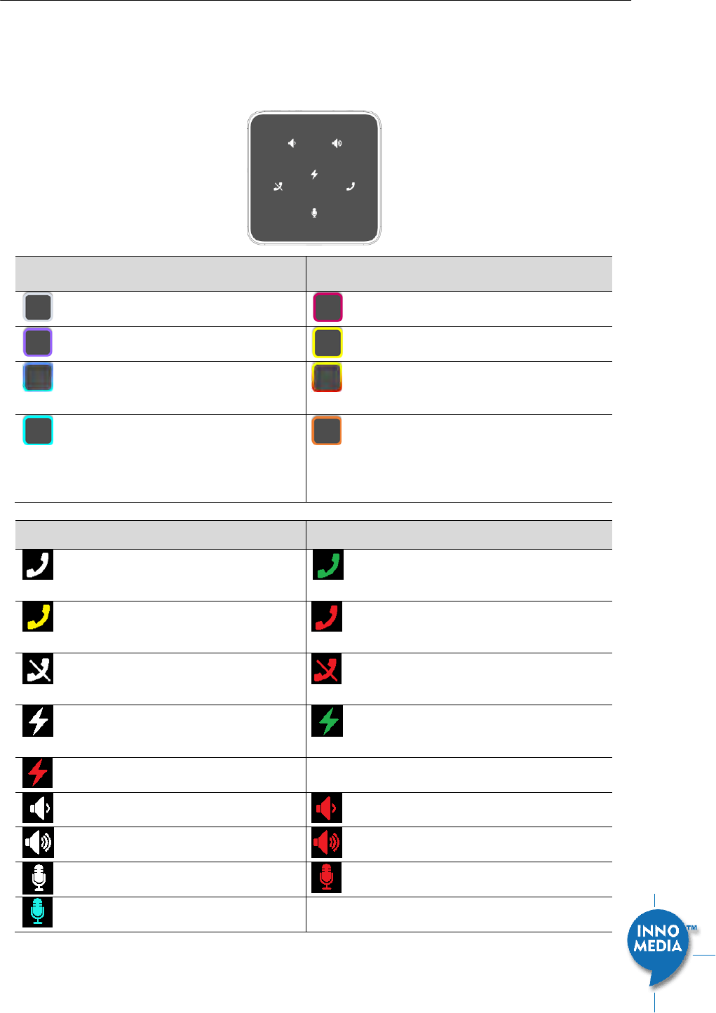
1.1.2 Box Control Panel
Ring
LED
State description
Ring
LED
State description
Not lit. Idle state and Ready to take
voice commands.
MIC off (red)
Purple.
Do not disturb on. Single flash.
Yellow.
Notifications.
Blue-Cyan.
Thinking. Altering at 620 ms
Speaking. Altering at 1260 ms
Yellow-Red
Notification queued and MIC off.
Cyan.
Listening.
Orange.
Spinning clockwise. While connecting
to the Internet during initialization.
Fading blinking. Fail to connect to
Internet, or system error.
icon
State description
icon
State description
Phone. Not-lit.
Ready to take command. Tap to make a
call.
Phone. Green.
[Ongoing call|Ringing] mode. No voice
mail.
Phone. Yellow.
Voice mails and registered.
Phone. Red
[BuddyTalk not setup|DND|Not
registered] mode
Unmute. Not lit.
Tap to mute.
Mute. Red.
[BuddyTalk not setup|Mute] mode. Tap to
unmute.
Flash key. Not lit.
Tap to merge calls, transfer a call, call
waiting …
Flash. Green for being tapped.
Buddytalk not setup. Red.
Volume down. Not lit.
Tap to lower volume
When speaker is muted. Red.
Volume up. Not Lit.
Tap to increase volume
When speaker is muted. Red.
MIC. Not lit.
Unmute. Tap to mute.
MIC mute. Red.
Tap to unmute.
Press for 3 seconds. Cyan.
[Listening|Speaking] mode. Tap to stop.
InnoMedia HG8328-1W Administrative Guide
Page 10
Copyright © 2019 InnoMedia. All rights reserved.
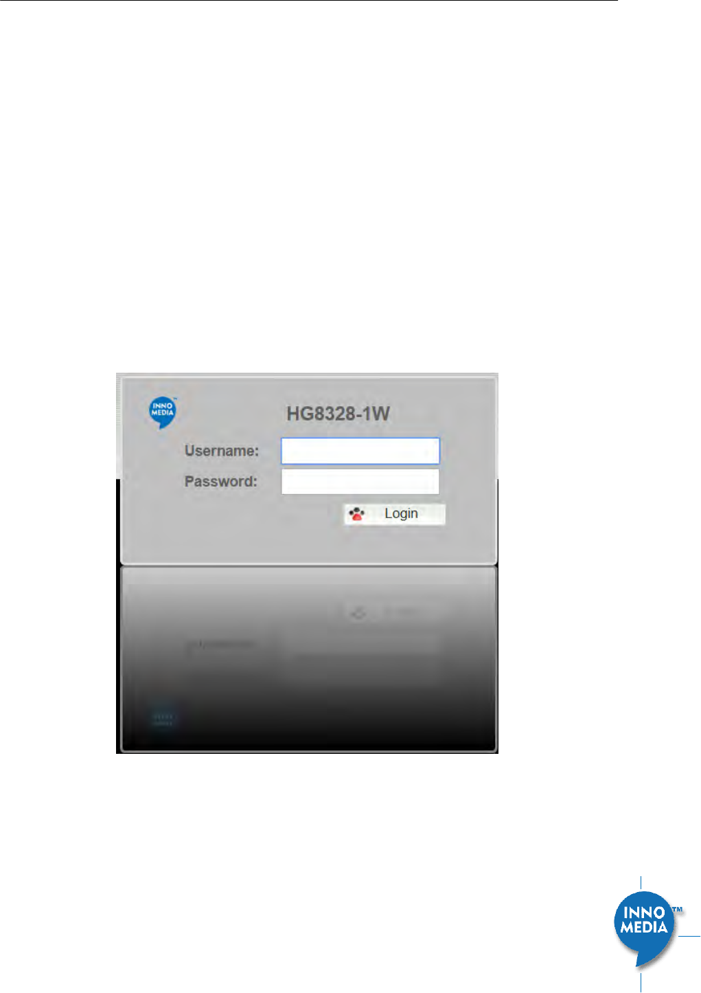
2 HOME -- DEVICE STATES
The HG can be managed via a Web Browser interface. Once the HG is connected to the network, connect a
device with a browser to the same router as the HG WAN interface. Access and configure the HG8328-1W via
a Web Browser.
Press ***1 on a phone connected to the HG and the IP address will be played through the telephone
handset.
When the Ethernet WAN interface is connected to the Router, the IP address played is always the Ethernet
WAN IP.
The default Admin Username is: admin
The default Password is: password
The default end user Username is: user
The default Password is: welcome
Note: The default username and password could be different if changed by the service provider.
Figure 3. Login Screen (Username and Password). HG8328-1W login screen example.
InnoMedia HG8328-1W Administrative Guide
Page 11
Copyright © 2019 InnoMedia. All rights reserved.
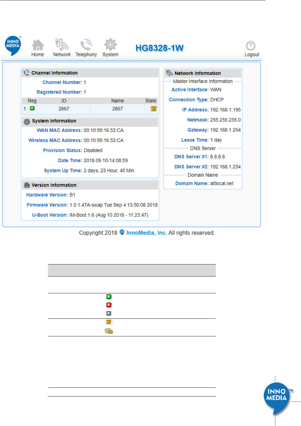
The Home page displays the device’s current status of HG8328-1W, the 1 FXS port model, as an example.
Figure 4. Current status of HG8328-1W
Field Name
Description
Channel
Information
Number of phone lines provisioned
Number of SIP accounts provisioned
Reg Status
Successfully REGISTERED with SIP proxy
Not REGISTERED with SIP proxy
Account disabled
State
Phone on hook
Phone off hook
System
Information
MAC address of Ethernet WAN
Provision Status: last provisioning date-
time and status
Date Time: current date and time
System Up Time: up time since last
power up.
Version
Hardware Version

InnoMedia HG8328-1W Administrative Guide
Page 12
Copyright © 2019 InnoMedia. All rights reserved.
Information
Firmware Version
Boot Loader Version
Network
Information
Master Interface Information: Current
active (in use) network.
DNS Server: all DNS server IP addresses
configured on the MTA devices. The
priority order of DNS servers (in order of
decreasing priority) used is: Master DNS
server(s) > those obtained from the
DHCP server > user configured DNS
server(s). See section 3.3 for details on
Master DNS.
Domain Name: the domain name
obtained from DHCP Option 15 or the
configured value described in section
3.2. The value obtained from DHCP has
higher priority than any manually
configured domain name.
InnoMedia HG8328-1W Administrative Guide
Page 13
Copyright © 2019 InnoMedia. All rights reserved.
3 NETWORK
The Network pages allow the configuration of the HG8328-1W network parameters.
3.1 IP Address Configuration for HG8328-1W
Configure IP address parameters for this device.
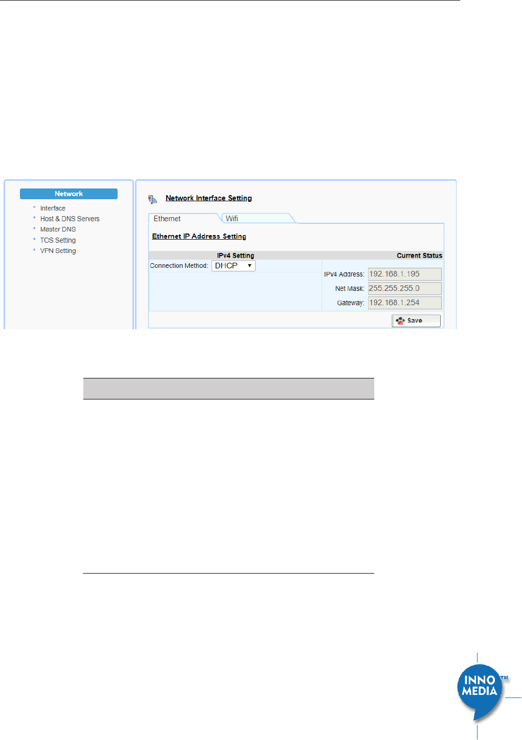
3.1.1 Ethernet IP Address Setting
Configure the IPv4 IP address for the device. Click the “Interface” menu from the left panel.
Figure 5. Configuring the IP Address on the Ethernet Interface
Field Name
Description
Connection
Method
DHCP: Automatically acquires IP address
from the Router.
Fixed IP: Need to configure the
following parameters according to the
Router network settings.
IPv4 IP address | Net Mask | Gateway |
MTU (maximum size of an IP packet, in
bytes).
Note that default value of MTU is 1500,
and its valid value ranges from 150 to
1500. Do not change the MTU value
unless necessary.
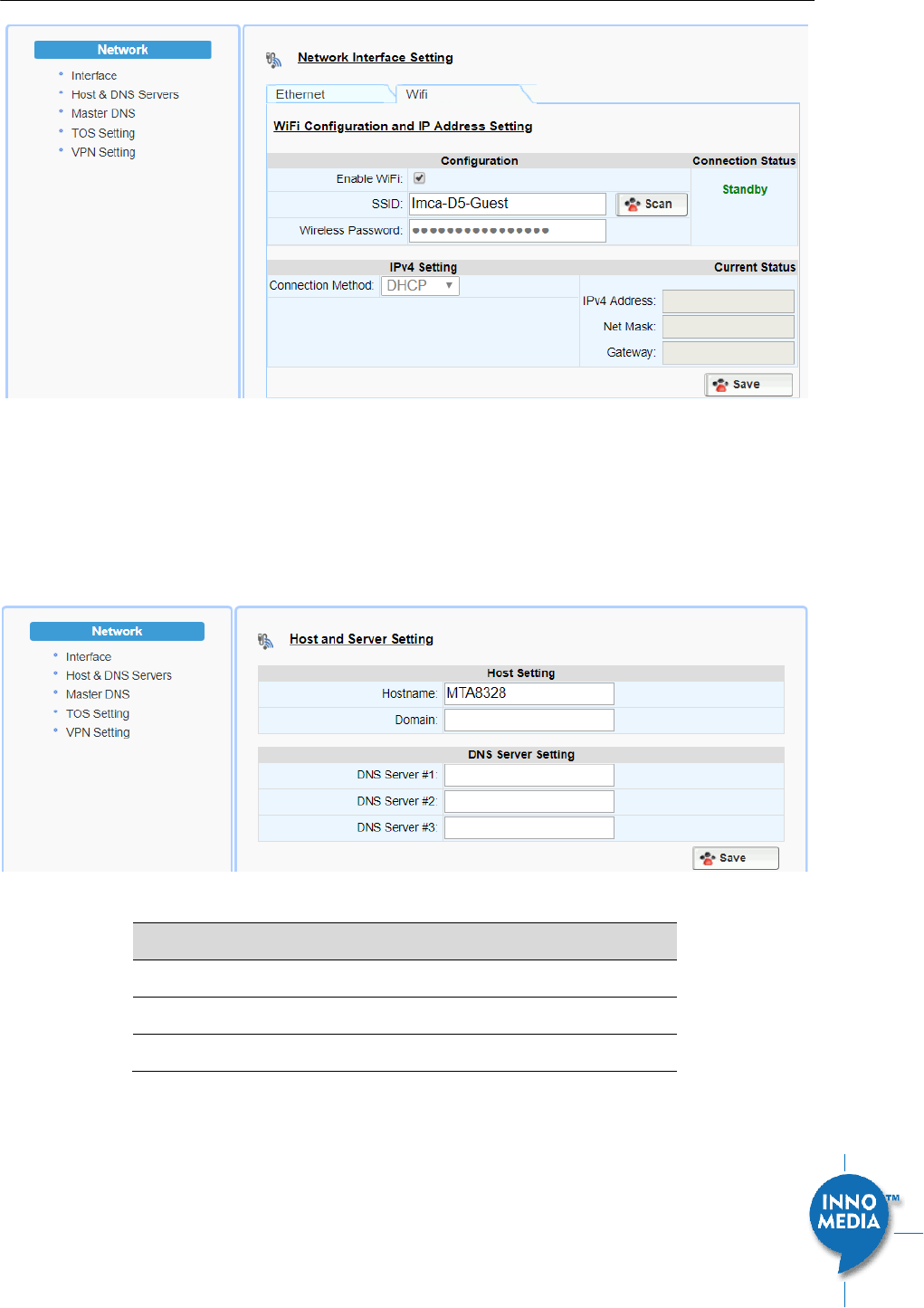
3.1.2 WiFi Configuration and IP Address Setting
This page is applicable to the HG8328-1W model.
InnoMedia HG8328-1W Administrative Guide
Page 14
Copyright © 2019 InnoMedia. All rights reserved.
Figure 6. WiFi Configuration and IP Address Setting
Select a WiFi SSID and input the password (Pass Phrase) for WiFi Access Point. Note that the WiFi password
cannot be retrieved from this page by the administrator if it is entered through the Captive Portal page.
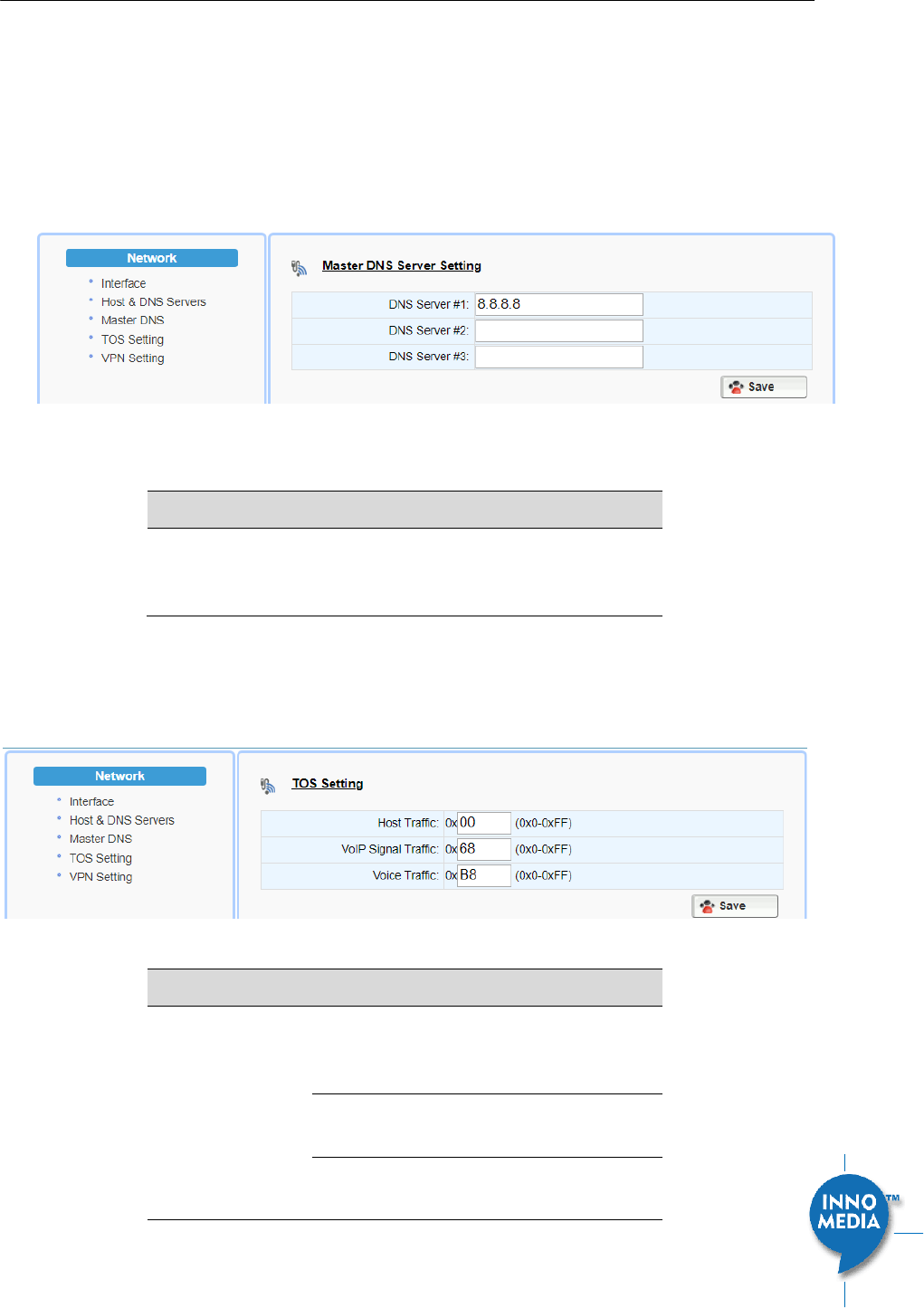
3.2 Host and DNS Servers
Configure the host and the DNS server information provided by your network operator.
Figure 7. Configuring the host information on the device
Field Name
Description
Host Name
Configure the host name for the device.
Domain
Configure the domain name for the device.
DNS Server Setting
Allows configuration of up to three DNS servers.
3.3 Master DNS
“Master DNS” is the IP address of the domain name server specified by the telephony service provider rather
than the internet service provider. If “Master DNS” is configured, the MTA gets related DNS services from this
InnoMedia HG8328-1W Administrative Guide
Page 15
Copyright © 2019 InnoMedia. All rights reserved.
configured server to perform voice communication functions. The MTA acquires DNS information from the
following servers in the priority shown (in order of decreasing priority):
1. Master DNS
2. DHCP Option (Ethernet IP Address Setting)
3. Manually configured DNS (see section 3.2)
Figure 8. Configuring the Master DNS Information
Field Name
Description
DNS Server
Configure the DNS server information
specified by the VoIP service provider for up
to 3 DNS servers.
3.4 TOS Setting
TOS (Type of Service) is a part of the IPv4 header which is used for precedence, or in other words categorizing
traffic classes. The higher the value of the IP Precedence field, the higher the priority of the IP packet.
Figure 9. TOS Setting
Field Name
Description
TOS Setting
Host Traffic: Use the configured TOS value to
tag data traffic other than SIP or RTP
packets.
VoIP Signal Traffic: Use the configured TOS
value to tag SIP signaling packets.
Voice Traffic: Use the configured TOS value
to tag voice RTP packets.
InnoMedia HG8328-1W Administrative Guide
Page 16
Copyright © 2019 InnoMedia. All rights reserved.
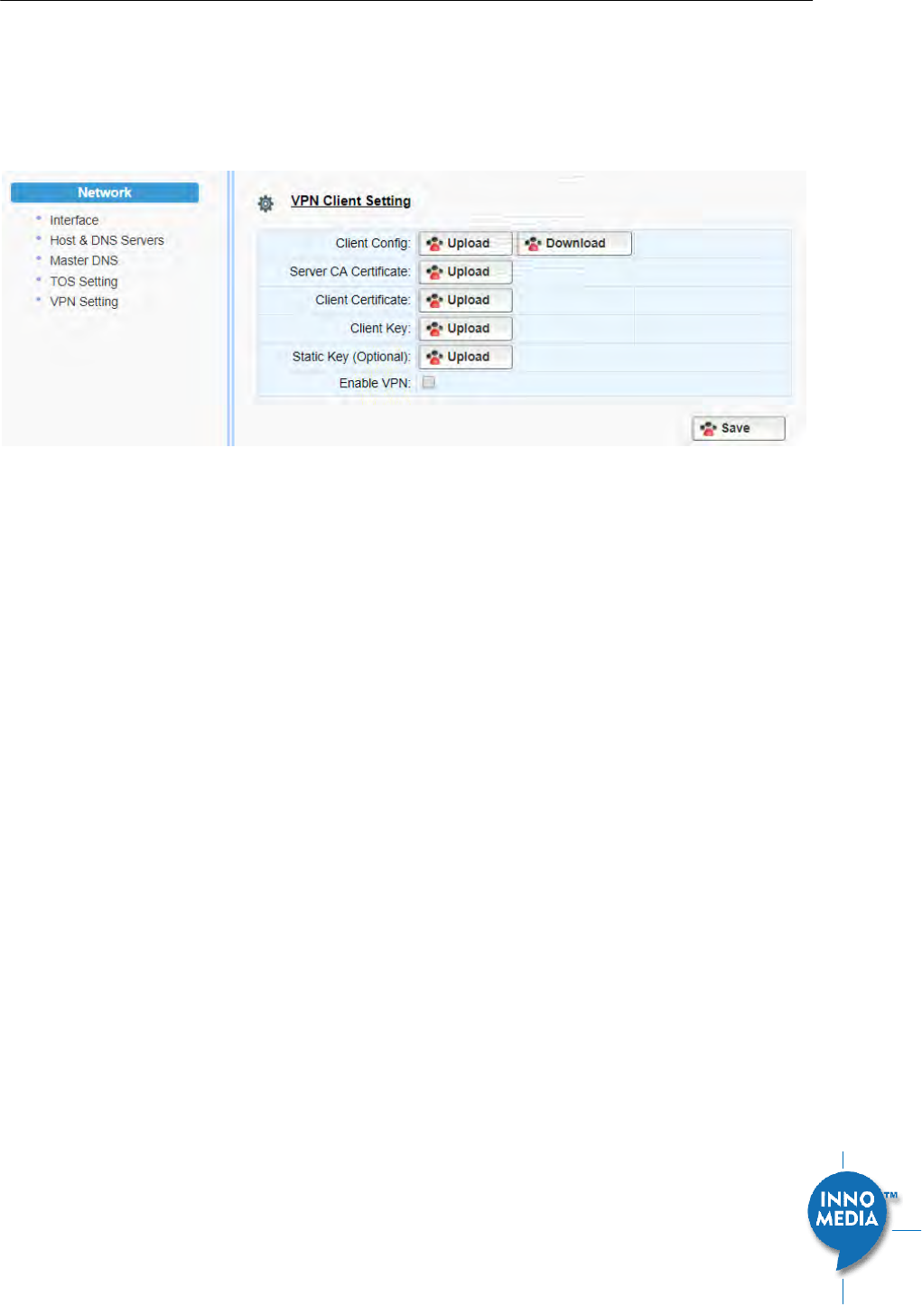
3.5 VPN
To setup the HG3828 to run as a VPN client, import the files which are provided by service providers, enable
VPN and save the configurations.
Once enabled, the HG8328-1W will automatically setup a VPN tunnel for voice services.
Figure 10. VPN client setup
InnoMedia HG8328-1W Administrative Guide
Page 17
Copyright © 2019 InnoMedia. All rights reserved.
4 TELEPHONY
The Telephony section is used to configure SIP Parameters, telephony settings (including regional settings)
and line diagnostics.
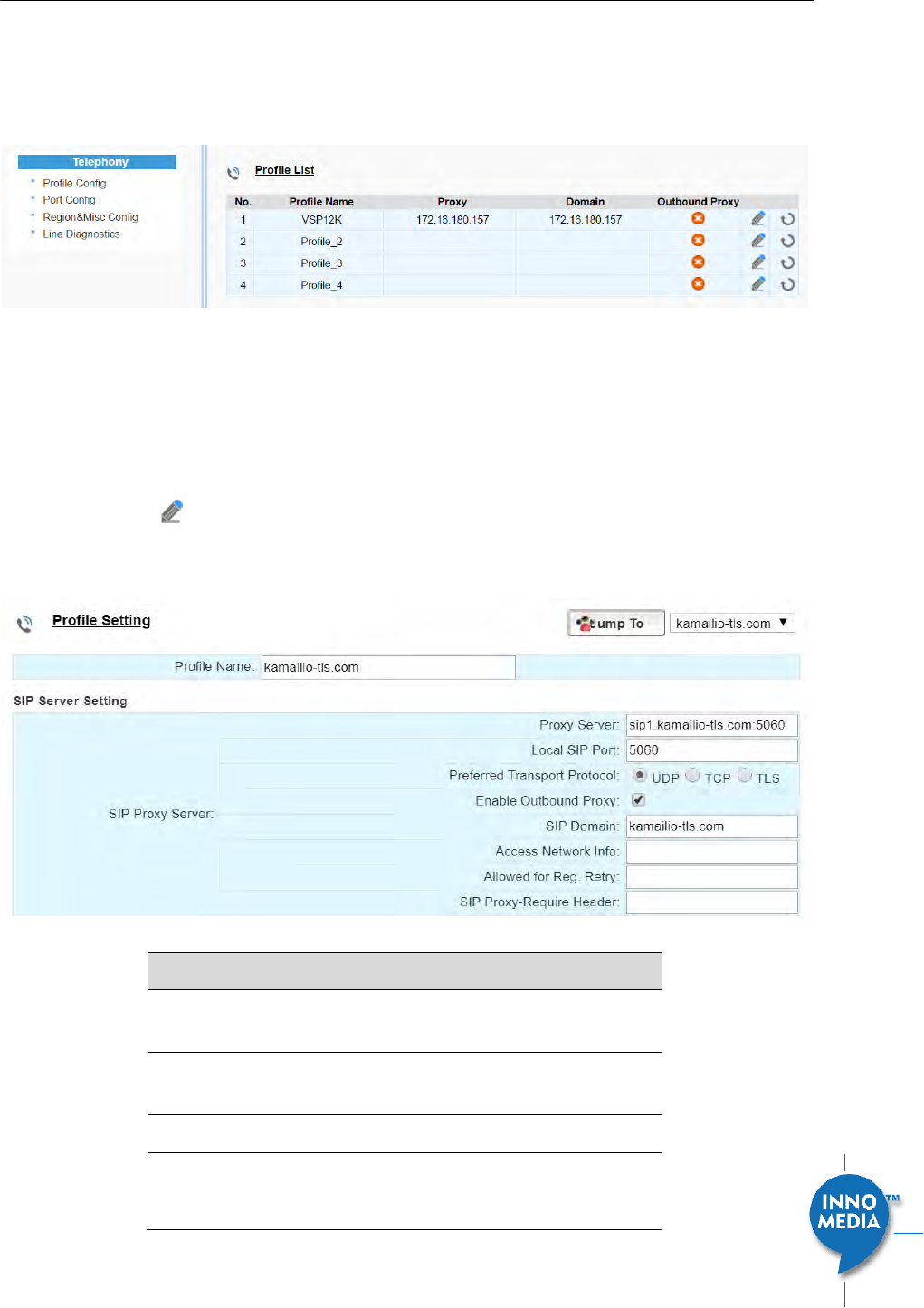
Figure 11 Configuring Telephony options
4.1.1 Profile Config
Profiles include SIP Server/Proxy Settings, Security Settings, Codec Settings, SIP Timer Settings, Digitmap
Settings, FXS Settings, Feature and Service Code Settings, Fax Settings and Call Report Settings which are
described in the following sections.
Click on the Edit icon of a particular profile to display the profile setting screen.
4.1.2 SIP Server Setting
Figure 12. SIP Server Setting—SIP Proxy Server
Field Name
Description
Profile Name
Up to 4 profiles can be created. (The profile
ID corresponds to the No. in the Profile List.)
Proxy Server
The FQDN or IP address of the SIP proxy
server
Local SIP Port
The SIP port used on the MTA
Preferred
Transport Protocol
If there are no queried NAPTR records
specifying the transport protocols to be
used, the MTA uses this configured setting
InnoMedia HG8328-1W Administrative Guide
Page 18
Copyright © 2019 InnoMedia. All rights reserved.
to set up VoIP calls with the SIP server.
UDP | TCP | TLS
Enable Outbound
Proxy
If enabled, the MTA uses the value
configured in “Proxy Server” as the
outbound proxy server setting.
SIP Domain
The MTA uses this setting to (1) compose
the host part of SIP request URI strings and
(2) perform NAPTR/SRV queries.
Access Network
Info
This header is useful in SIP-based networks
that also provide layer 2/layer 3 connectivity
through different access technologies. SIP
User Agents may use this header to relay
information about the access technology to
proxies that are providing services.
Allowed for Reg.
Retry
Upon registration failure, the configured
registration response SIP error codes can be
used to trigger re-registration. If multiple
error codes are to be used, use a comma (,)
to separate them. No entry indicates
registration is always retried if registration
fails.
SIP Proxy-Require
Header
The Proxy-Require header field is used to list
features and extensions that a UA requires a
proxy to support in order to process the
request.
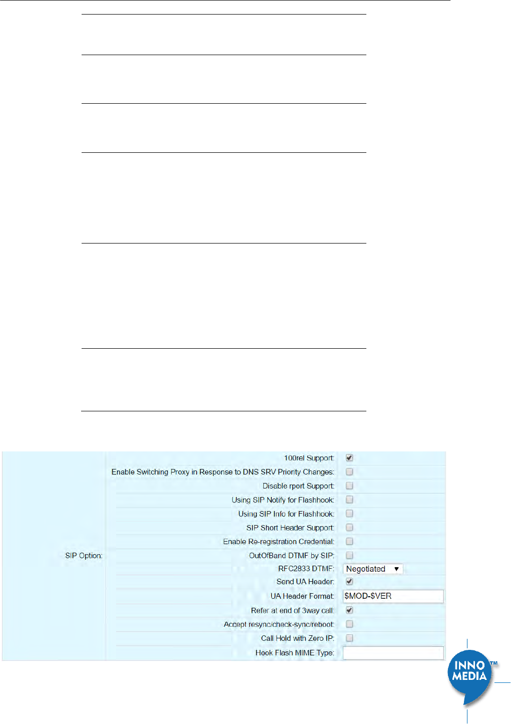
Figure 13. SIP Server Settings – SIP Option

InnoMedia HG8328-1W Administrative Guide
Page 19
Copyright © 2019 InnoMedia. All rights reserved.
Field Name
Description
100rel Support
Enable 100rel response support.
Enable Switching
Proxy in Response
to DNS SRV Priority
Change
When this item is enabled, whenever the
MTA is ready to send a REGISTER request
and the SRV TTL has expired, it performs an
SRV query and the MTA will switch to the
most preferred SIP server (lowest priority) in
the SRV query response.
If this item is disabled, the MTA stays with
the currently registered SIP proxy and only
saves the SRV query results. However, if the
current SIP proxy is unreachable, or the MTA
reboots and starts a new DNS query process,
the MTA will then register to the most
preferred SIP server (lowest priority) in the
SRV query response.
Disable rport
Support
Do not append rport (response port
number) in the Via header.
Using SIP Notify for
Flashhook Support
Send a SIP NOTIFY hook flash event message
during the call when a hook flash is
detected.
Using SIP Info for
Flashhook Support
Send a SIP INFO hook-flash event message
during the call when a hook flash is
detected.
SIP Short Header
Support
Send SIP Headers in short format (compact
form) to reduce message packet size.
Enable Re-
registration
Credential
Enable Re-registrations to carry the previous
successful authentication credentials.
OutOfBand DTMF
by SIP
Use SIP INFO to send DTMF.
RFC2833 DTMF
Use RFC2833 for sending DTMF digits.
Available options:
Negotiated – MTA and SIP Server
negotiate if RFC2833 is enabled or not.
Always off – RFC2833 is never used.
Always on – RFC2833 is always used.
Send UA Header
Allow MTA to send User-Agent Header in SIP
message.
UA Header Format
User-Agent Header sent out is modifiable.

InnoMedia HG8328-1W Administrative Guide
Page 20
Copyright © 2019 InnoMedia. All rights reserved.
(Note: If “SIP Short Header Support” is
enabled, there will be no UA Header in SIP
messages.)
Available parameters:
Model name ($MOD)
MAC ($MAC)
Version ($VER)
Example Syntax: $MOD $MAC $VER.
Output: SIP User-Agent: MTA-8328-1N
001099112233 V1.0.0.0
Refer at End of
3way Call
Send REFER when mixer (local MTA) hangs
up, so the other two parties can continue
the conversation.
Accept
resync/check-
sync/reboot
When enabled, the MTA device supports
events triggered by SIP NOTIFY messages
sent to the MTA from the SIP server. Event
types are:
(1) check-sync. MTA reboots itself and
starts provisioning process.
(2) reboot. MTA reboots itself (and starts
provisioning process).
(3) resync. MTA starts provisioning process
only.
Call Hold with Zero
IP
Use 0.0.0.0 in SDP for call hold.
Hook Flash MIME
Type
Input the MIME type string for Flash hook
events.
4.1.3 Security Setting
Figure 14. MTA Security Settings
Field Name
Description
Enable SIP Server
List
When this feature is enabled, the MTA
checks all incoming SIP request messages for
their source IP addresses. If the source IP is
not in the “SIP Server list”, the MTA rejects
or drops this message.
InnoMedia HG8328-1W Administrative Guide
Page 21
Copyright © 2019 InnoMedia. All rights reserved.
The MTA initially creates a “SIP Server list”
which contains the IP addresses resolved
from the settings of “Proxy Server”, “SIP
Domain” and the “EMS Server”. See also
below for adding additional Trusted SIP
entities.
Action on Failed
Validation
Drop silently. The MTA simply drops the
incoming SIP request messages.
Reject with 400. The MTA replies with an
error SIP response code of 400 to the
sender.
Additional Trusted
SIP Entities
Input one or more addresses (IP or FQDN)
for additional servers from which the MTA
will accept incoming SIP messages. These
servers are in addition to those in the “SIP
Server List” which the MTA automatically
creates (see above).
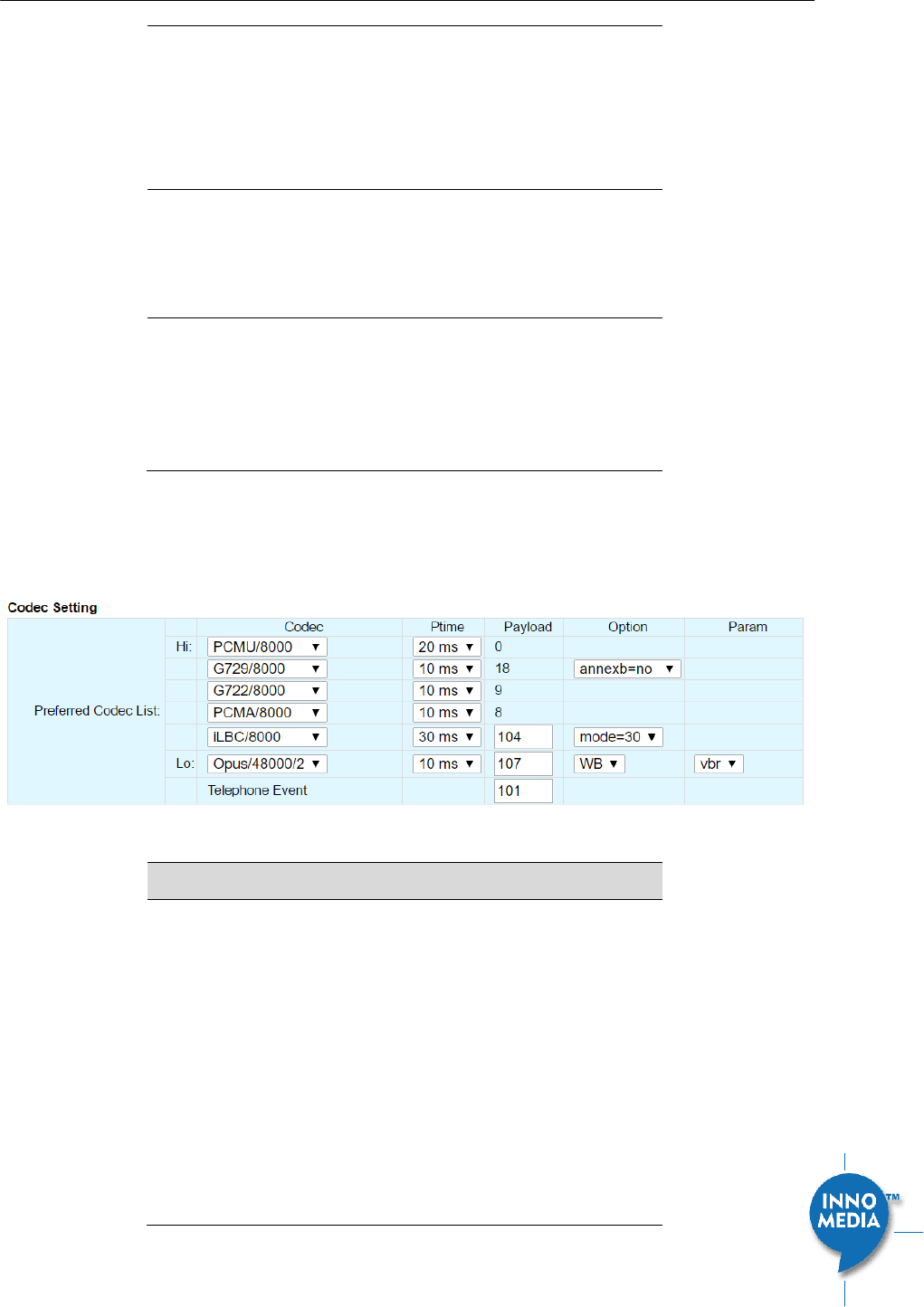
4.1.4 Codec Setting
Configure voice codecs allowed by service providers for telephony services.
Figure 15. Codec Setting
Field Name
Description
Preferred Codec
List
List the Codecs to be enabled for this profile
and their order of importance.
Available Codecs:
PCMU/8000 – Set Ptime
PCMA/8000 – Set Ptime
G729/8000 – Set Ptime and annexb on
or off
G722/8000 – Set Ptime
iLBC/8000 – Set Ptime, dynamic payload
type, and mode (codec frame size, 20ms
InnoMedia HG8328-1W Administrative Guide
Page 22
Copyright © 2019 InnoMedia. All rights reserved.
or 30ms)
Opus/48000/2 - Set Ptime, dynamic
payload type, wideband|narrowband
mode, and vbr (variable bit rate)|cbr
(constant bit rate).
Telephone Event
RFC2833 payload type
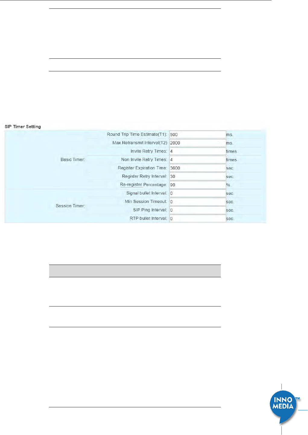
4.1.5 SIP Timer Setting
SIP timers define transaction expiration timers, retransmission intervals when UDP is used as a transport, and
the lifetime of dynamic TCP connections. The retransmission and expiration timers correspond to the timers
defined in RFC 3261.
Figure 16. SIP Timer Setting
Basic Timer
Description
Round Trip Time
Estimate (T1)
Estimated time it takes for a packet to make
a round trip from the device to the far end
and back.
Max Retransmit
Interval (T2)
The maximum retransmit interval for non-
INVITE requests and INVITE responses.
Invite Retry Times
The maximum number of times that a SIP
INVITE is retransmitted if no response is
received. According to RFC3261, INVITE
requests are retransmitted at an interval
which starts at T1 and doubles until it hits
T2, and then repeats at interval T2. The
MTA stops retries when a 32 second cap is
reached, or the max number of INVITE
retries has been attempted.

InnoMedia HG8328-1W Administrative Guide
Page 23
Copyright © 2019 InnoMedia. All rights reserved.
Non Invite Retry
Times
The maximum number of times that a SIP
message other than an INVITE request is
retransmitted if no response is received.
According to RFC3261, Non-INVITE requests
are retransmitted at an interval which starts
at T1 and doubles until it hits T2, and then
repeats at interval T2. The MTA stops
retries when a 32 second cap is reached, or
the max number of non-INVITE retries has
been attempted.
Register Expiration
Time
Time to wait after a registration before it
expires.
Generic SIP version: If the timer is set to
be x seconds, the MTA re-registers at
$ReregisterPercentage% of the
expiration time (e.g., x*90% seconds).
IMS version: If value is greater than
1200 sec, the MTA will re-register 600
seconds before registration time
expires. If less than or equal to 1200
seconds, it will re-register when half of
the expiration time expires.
Register Retry
Interval
The time interval in seconds in which the SIP
Device will retry registration when the retry
interval expires, after a SIP Registration
failure, as long as the “retry-after” SIP
header field is non-zero. This behavior is also
dependent on the “Allowed for Reg. Retry”
(in section 4.1.2) configuration as this
determines if the MTA will retry registration.
Re-register
Percentage
Configure the time for the MTA to Re-
register based on the percentage of the
value of Registration Expiry Time.
Session Timer
Description
Signal bullet
Interval
Time between sending dummy keep-alive
UDP packets. Set to 0 to disable sending out
signaling bullet packets
Min Session
Timeout
Enable session Audit.
SIP Ping Interval
Time interval between sending SIP OPTIONS
ping messages.
RTP bullet Interval
Time between sending an empty keep-alive
RTP packet to keep a port open. Set to 0 to
disable sending out RTP bullet packets.
InnoMedia HG8328-1W Administrative Guide
Page 24
Copyright © 2019 InnoMedia. All rights reserved.
4.1.6 DigitMap Setting
Digitmaps are templates that match different sequences of digits that users dial as part of their interaction
with their phone system. After the user dials, when there is a match between the digits dialed and the
digitmap, the MTA device sends the digits to the server to initiate the call. If there is no match, the system
waits for the user to enter more digits or press the send key to indicate dialing is complete.
Load the SIP device with the digitmap pattern which corresponds to the dial plan selected by the service
operator. The digitmap is expressed in a format derived from the UNIX system command, “egrep.” You must
build the digit map based on the dialing plan which you wish to support.
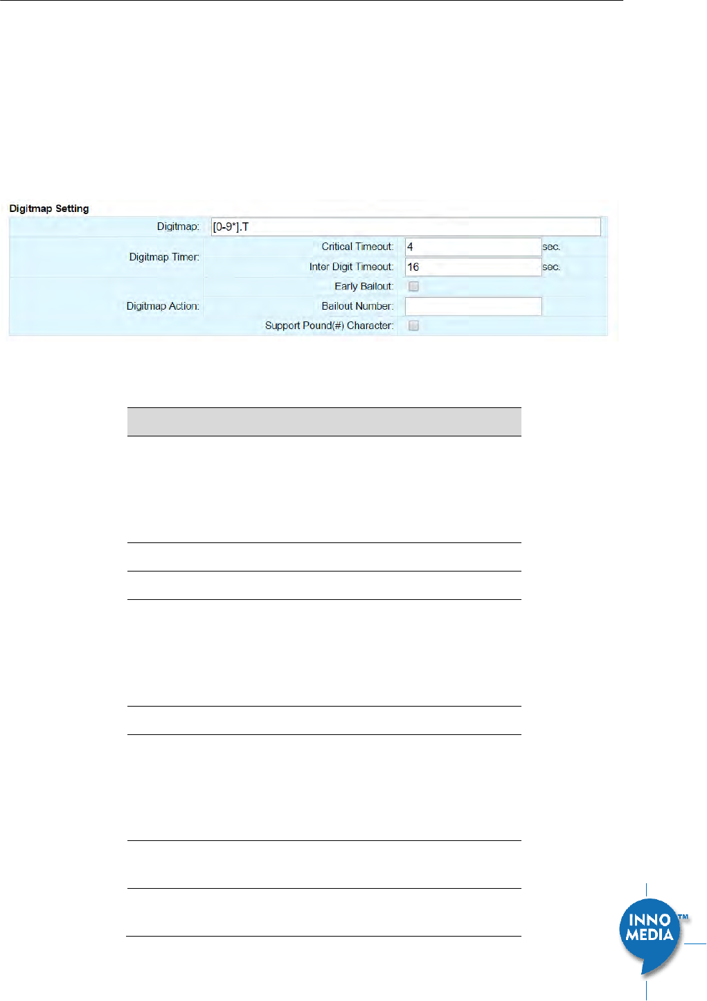
Figure 17. Digitmap Setting
Digitmap
Description
Digitmap
Define patterns of dial strings that the MTA
can send to the SIP server when the pattern
has been met, and not have to wait for the
InterDigit Time out or the Critical Timeout.
This helps improve call completion times.
Digitmap Timer
Critical Timeout
Short timeout if match digitmap T pattern.
Inter Digit Timeout
Time to wait between digits being dialed
before assuming no more entries are to be
made. This is required to ensure a pause in
dialing does not trigger an incomplete
number to be sent to the SIP server.
Digitmap Action
Early Bailout
If a dialed number does not match any
digitmap pattern, call a predefined bailout
number. This number may be configured as
an announcement to inform the user that
this is an invalid number.
BailOut Number
The outgoing number when early bailout is
enabled.
Support Pound (#)
Char
This feature only controls the “#” at the end
of a dialed string.

InnoMedia HG8328-1W Administrative Guide
Page 25
Copyright © 2019 InnoMedia. All rights reserved.
If this feature is enabled, pressing pound (#)
after dialing numbers will cause the MTA to
dial out immediately without waiting for the
expirations of associated timers, e.g.,
“Critical Timeout” and “Inter Digit Timeout”.
If this feature is disabled, and there are
associated digitmap rules ended with a “#”
sign, the MTA sends out “%23”, which is
equivalent to “#”.

InnoMedia HG8328-1W Administrative Guide
Page 26
Copyright © 2019 InnoMedia. All rights reserved.
4.1.6.1 A Digitmap Example
0
Local operator
00
Long distance operator
[1-7]xxx
Local extension number
8xxxxxxx
Local number
#xxxxxxx
Shortcut to local number at other corporate sites
[0-9*].#
Any dialed numbers followed by a “#” sign
*xx
Star services
91xxxxxxxxxx
Long distance number
9011 + up to 15 digits
International number
The dial plan described above results in the following digit map:
(0| 00|[1-7]xxx|8xxxxxxx|#xxxxxxx|*xx|91xxxxxxxxxx|9011x.T|[0-9*].#)
4.1.6.2 Digitmap syntax
A DigitMap, according to this syntax, is defined either by a (case insensitive) “String” or by a “list of strings”
over which the SIP Device will attempt to find a shortest possible match. Regardless of the above syntax, a
timer is currently only allowed if it appears in the last position in a string. Each string in the list is an alternate
numbering scheme.
The formal syntax of the digit map is described by the following notation:
Digit ::= “0” | “1” | “2” | “3” | “4” | “5” | “6” | “7” | “8” | “9”
Timer ::= “T” | “t” -- matches the detection of a timer
Letter ::= Digit | Timer | “#” | “*” | “A” | “a” | “B” | “b” | “C” | “c” | “D” | “d”
Range ::= “X” | “x” -- matches any single digit
| “[“ Letters “]” -- matches any of the specified letters
Letters ::= Subrange | Subrange Letters
Subrange ::= Letter -- matches the specified letter
| Digit “-” Digit -- matches any digit between first and last
Position ::= Letter | Range
StringElement ::= Position -- matches an occurrence of the position
| Position “.” -- matches an arbitrary number of occurrences of the position, including 0
String ::= StringElement | StringElement String
StringList ::= String | String “|” StringList
DigitMap ::= String | “(“ StringList “)"
InnoMedia HG8328-1W Administrative Guide
Page 27
Copyright © 2019 InnoMedia. All rights reserved.
4.1.6.3 FXS Setting
FXS port configuration allows you to set parameters based on the requirements of the telephony connection.
You can alter the default settings and fine-tune the parameters for specific needs. For example, you might
need to configure the ring timeout duration dependent on your needs. You can set the following
configuration parameters for an FXS port:
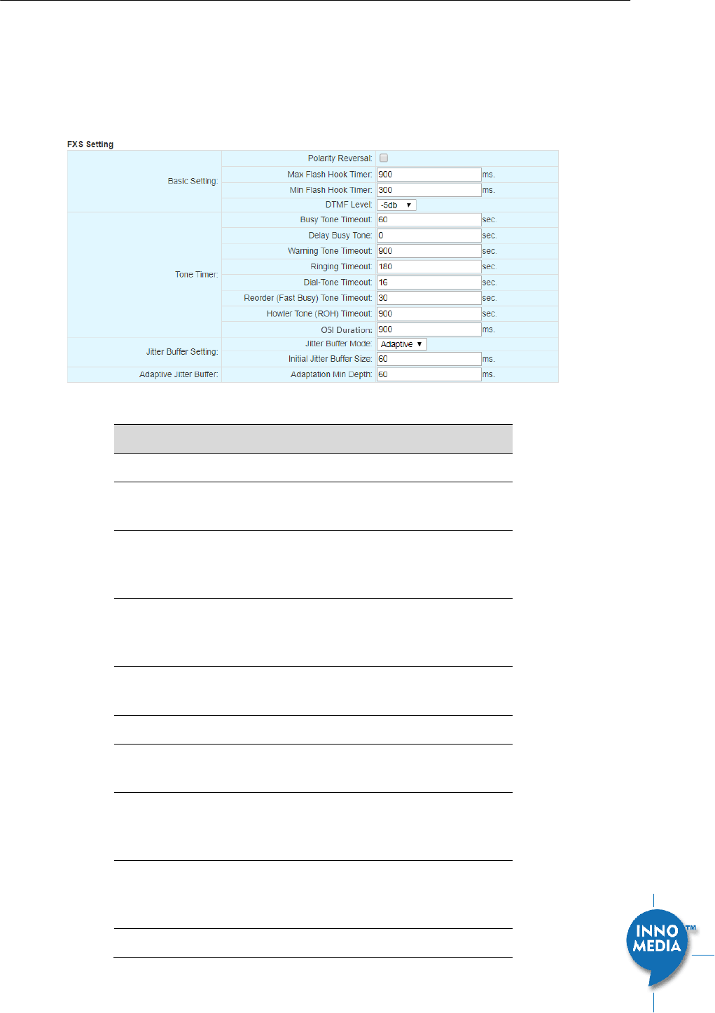
Figure 18. FXS Setting
Field Name
Description
Basic Setting
Polarity Reversal
Enable Polarity Reversal – Tip and Ring are
reversed when a call is answered.
Max Flash Hook
Timer
The maximum flash hook cannot last more
than X ms for the MTA to treat it as a Flash
Hook.
Min Flash Hook
Timer
The minimum flash hook needs to last at
least X ms before MTA treats it as a Flash
Hook.
DTMF Level
The level of Dual Tone Multi Frequency
tones.
Tone Timer
Busy Tone Timeout
Busy Tone will play for xx seconds and then
drop the call.
Delay Busy Tone
If the phone is in an off hook state, the time
duration that the MTA waits before playing
busy tone.
Warning Tone
Timeout
When the remote side hangs up, after the
busy tone time out, the device will start to
play warning tone for this period of time.
Ringing Timeout
Will ring a line for this period of time and
InnoMedia HG8328-1W Administrative Guide
Page 28
Copyright © 2019 InnoMedia. All rights reserved.
then cancel the call.
Dial-Tone Timeout
Will play Dial Tone for this period of time
and then play fast busy.
Reorder (Fast Busy)
Tone Time Out
Will play fast busy tone for this period of
time and then play Howler tone.
Howler Tone (ROH)
Time out
Will play Howler tone for this period of time
and then become silent.
OSI Duration
When a call is terminated, place line in open
circuit for X ms. A value of 0 disables OSI.
Jitter Buffer
Setting
Jitter Buffer Mode
Adaptive – Jitter Buffer Size changes
during the call in response to network
conditions.
Fixed – Jitter Buffer Size stays at the
programmed value.
NetEQ–when NetEQ is selected, the
‘Initial Jitter buffer size,’ and
‘adaptation Min Depth’ values are not
used.
Initial jitter buffer
size
The initial jitter buffer size in ms.
Adaptation Min
Depth
If network conditions are good, and no late
packets are detected, the jitter buffer will
continue to decrease until it meets the
configured size.
4.1.7 Feature and Service Code Setting
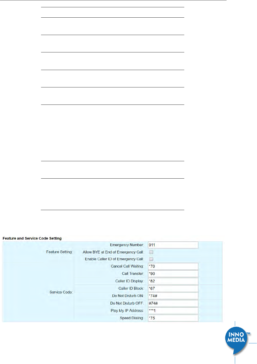
Figure 19. Feature and Service Code Setting

InnoMedia HG8328-1W Administrative Guide
Page 29
Copyright © 2019 InnoMedia. All rights reserved.
Field Name
Description
Feature Setting
Emergency
Number
If the entered number is dialed, all call
features are disabled. (Call Waiting, Call
Transfer, etc…)
Allow BYE at End of
Emergency Call.
If enabled, when you hang up a call to an
emergency number, treat this as a normal
call hang-up. If it is disabled, the MTA will
ring the phone when you hang up instead of
terminating the call.
Enable Caller ID of
Emergency Call
If Caller ID is enabled, on an outbound call to
the Emergency Number, Caller ID will be
sent.
Service Code
The following settings are applicable to
device based call features.
Cancel Call Waiting
The service code to cancel/resume receiving
and answering an incoming call when this
line is engaged on a call.
Call Transfer
The service code to transfer the current call
to another destination.
Caller ID Display
The service code to display the incoming
caller phone number and its display name.
Caller ID Block
The service code to hide the outbound caller
phone number and its display name.
Do Not Disturb ON
The service code for “Do Not Disturb-On”,
prevents incoming calls from ringing the
phone.
Do Not Disturb OFF
The service code for “Do Not Disturb-Off”,
allows incoming calls to ring the phone.
Play My IP Address
When a phone is connected to the MTA, and
this service code is dialed, the current MTA
IP address will be played out to the phone
handset.
Speed Dialing
Enter a prefix to use with the Speed Dialing
Settings under the Port Config section. For
example, if you configure a #9 in this setting,
to dial the phone number for Speed Dialing
Settings 0, simply dial a #90. Ensure the
Prefix and Speed Dialing Settings don't cause
a dialing conflict with other features such as
Call Transfer and Caller ID Display.
InnoMedia HG8328-1W Administrative Guide
Page 30
Copyright © 2019 InnoMedia. All rights reserved.
4.1.8 Fax Setting
Configure the parameters for sending and receiving a fax over the VoIP channel. Two major approaches can
be used for fax over IP.
G.711, sending fax signals in-band using the coding method used in regular voice transmissions, or
T.38, a protocol that sends fax image data over the IP network. T38 is designed for more efficient and
robust transmission compared to using the same method as voice communications.
There are pros and cons of both approaches described above. Consult your service provider for the
appropriate configuration when needed.
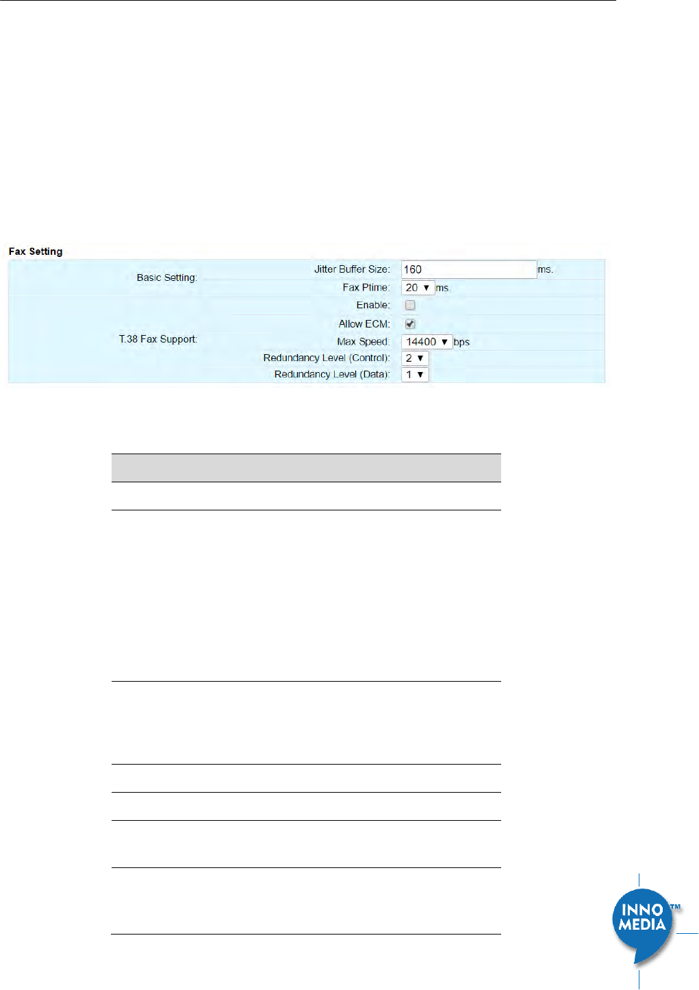
Figure 20. Fax Setting
Field Name
Description
Basic Setting
Jitter Buffer Size
A jitter buffer temporarily stores arriving
packets in order to minimize the impact of
delay variations.
If the jitter buffer size is too small, then an
excessive number of fax packets may be
discarded when network jitter occurs. If a
jitter buffer is too large, then it introduces
additional delay.
Fax PTime
Available Options:
10, 20, 30, 40, 50, 60 (ms).
T38 Setting
Enable T38
Enable/Disable T.38 Fax feature.
Allow ECM
Enable Error Correction Mode (ECM) for fax
transmission.
Max Speed
Bit Rate. Choose a maximum fax
transmission speed to be attempted: 2400,
4800, 9600, or 14400.
InnoMedia HG8328-1W Administrative Guide
Page 31
Copyright © 2019 InnoMedia. All rights reserved.
Redundancy Level
(Control)
Low Speed Redundancy. Number of
redundant T.38 fax packets to be sent for
the low speed V.21-based T.30 fax machine
protocol. Default value is 2. Do not change
the default value unless necessary.
Redundancy Level
(Data)
High Speed Redundancy. Number of
redundant T.38 fax packets to be sent for
high-speed V.17, V.27ter and V.29 fax
machine image data. Default value is 1. Do
not change the default value unless
necessary.
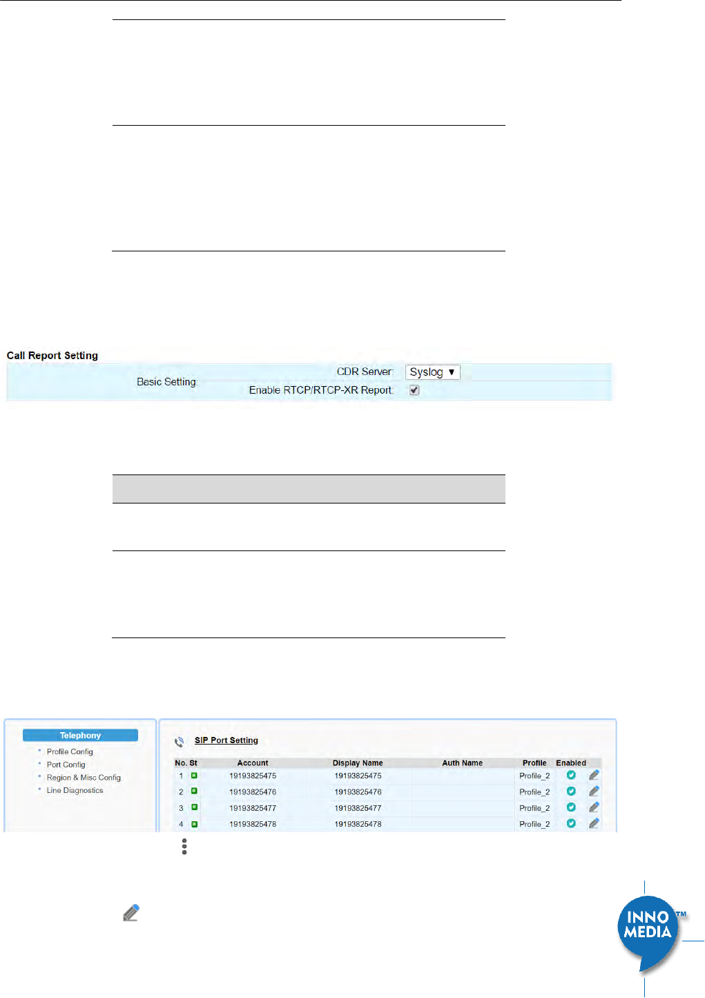
4.1.9 Call Report Setting
Configure Call Detail report setting. When a call terminates, the MTA will generate and send the CDR details
of the terminated phone call to a CDR server. In addition, the MTA can send RTCP-XR reports within the call.
Figure 21. CDR Setting
Field Name
Description
CDR Server
Send call detail records to (1) syslog server
or (2) EMS server or (3) none.
Enable RTCP-XR
Report
Check this item to enable the MTA to send
RTCP-XR sender reports. The RTCP-XR
reports will include voice quality analysis
(such as R-Factor & MOS).
4.2 Port Config
SIP Port Setting – List of current SIP user accounts. You may configure each user account from this page.
Figure 22. Phone port status overview
Click on the Edit icon of a particular user account to display the account setting screen.
InnoMedia HG8328-1W Administrative Guide
Page 32
Copyright © 2019 InnoMedia. All rights reserved.
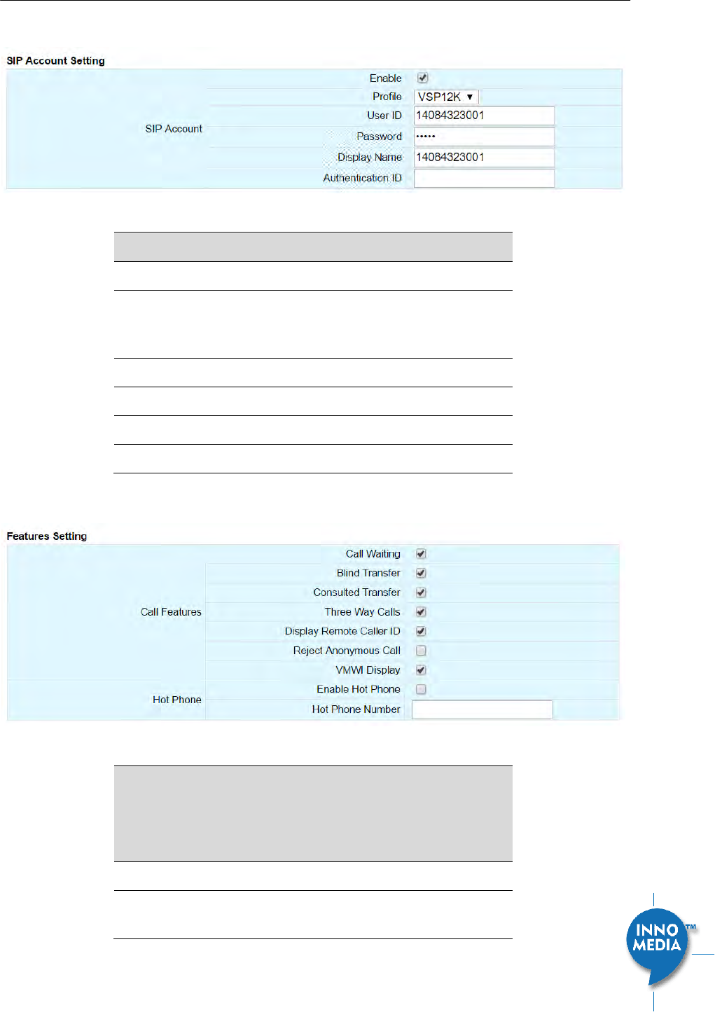
4.2.1 SIP Account Setting
Figure 23. SIP Account Setting
Field Name
Description
Enable
Enable/Disable SIP User Account.
Profile
Choose which Profile Name created under
Profile Config should be used for this
account.
User ID
Account User ID/Name.
Password
Account Password.
Display Name
Name to be displayed for Caller ID.
Authentication ID
Authentication ID if needed.
4.2.2 Features Setting
Figure 24. Call Feature Setting
Field Name
Description
The following call features use “Service
Codes” for device based call features
defined in the “Profile Setting” page section.
Call Features
Call Waiting
To receive and answer an incoming call
when this line is engaged in an active call.

InnoMedia HG8328-1W Administrative Guide
Page 33
Copyright © 2019 InnoMedia. All rights reserved.
Blind Transfer
Blind transfer is when a call is routed to a
third party and the original call is transferred
without any check being made to determine
whether the transferred call is answered or
if the number is busy.
Consulted Transfer
Consulted Call Transfer is used for
transferring a call to another destination
without releasing the call from the voice
platform until after the call is successfully
transferred.
Three Way Calls
3-Way Calling connects a third person to the
current two-way conversation.
Display Remote
Caller ID
Display of Caller ID (the caller phone number
and display name) for inbound calls from a
remote party.
Reject Anonymous
Call
Rejection of Anonymous inbound calls.
VMWI Display
To enable/disable MTA to display a voice
mail waiting indicator.
Hot Phone
Enable Hot Phone
Hot Phone feature that automatically dials
the Hot Phone Number when the phone is
taken off hook.
Hot Phone Number
Enter the phone number that the MTA dials
automatically when the phone is taken off
hook.
4.2.3 Line Setting
Line setting page includes input-MIC/output-speaker volume controls (gain controls) and the way silence
suppression is performed.
Figure 25. Line Setting
Field Name
Description
Voice Gain
Speaker Gain
Downstream volume control in the direction
InnoMedia HG8328-1W Administrative Guide
Page 34
Copyright © 2019 InnoMedia. All rights reserved.
from the network to the MTA’s analog
output.
Mic Gain
Upstream volume control in the direction
from the MTA’s analog input to the network.
Line Options
Silence
Suppression
Silence Suppression involves not
transmitting voice packets when one of the
parties involved in a call is not speaking.
Available options:
Negotiated
Disabled
Echo Cancellation
Enable or disable line echo cancellation.
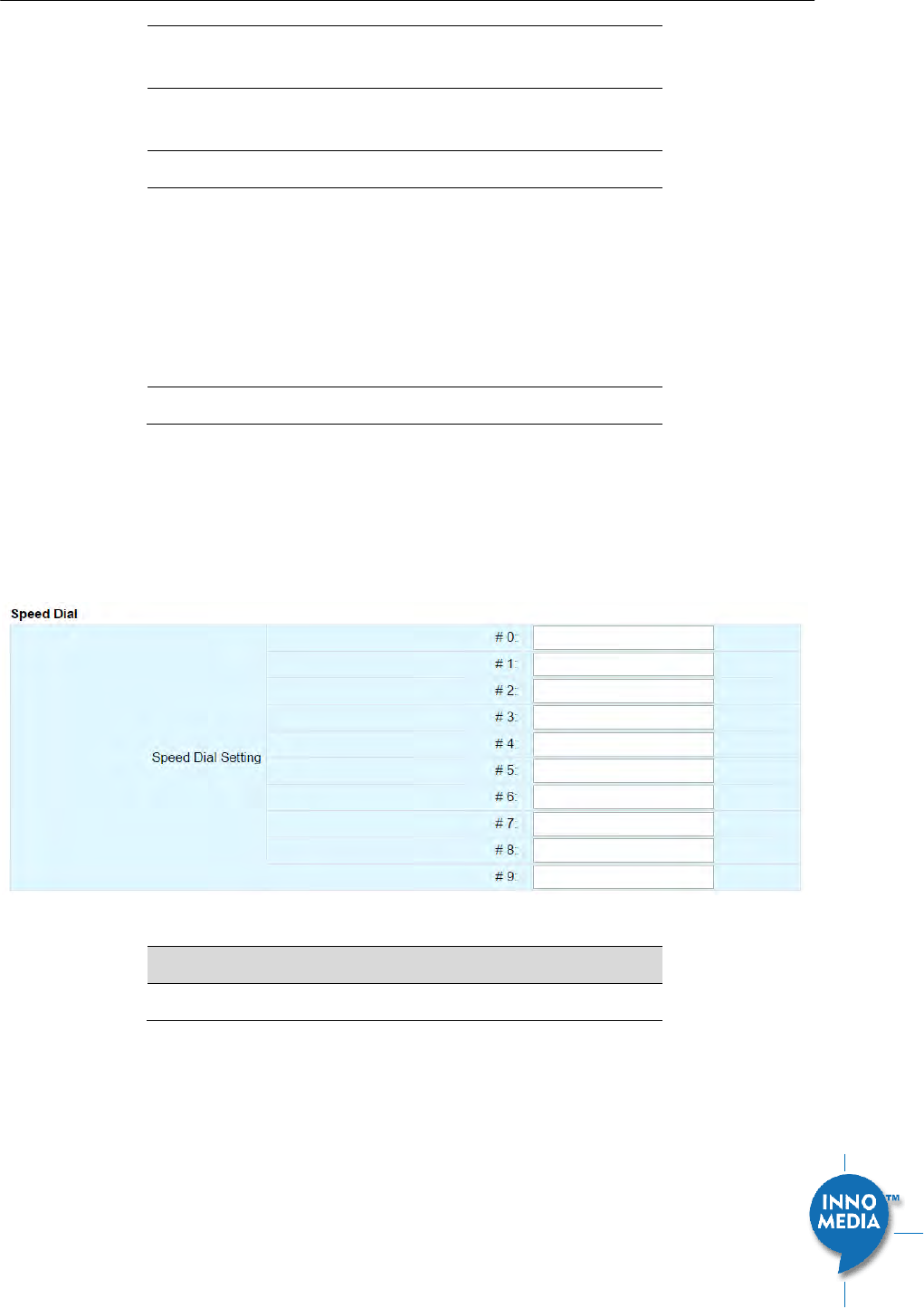
4.2.4 Speed Dial
Speed dial is a function to place a call by pressing a reduced number of keys. This function is particularly
useful for phone users who dial certain numbers on a regular basis. Please refer to section 4.1.7 for more
details on using speed dials.
Figure 26. Speed Dial
Field Name
Description
Speed Dial Testing
0-9
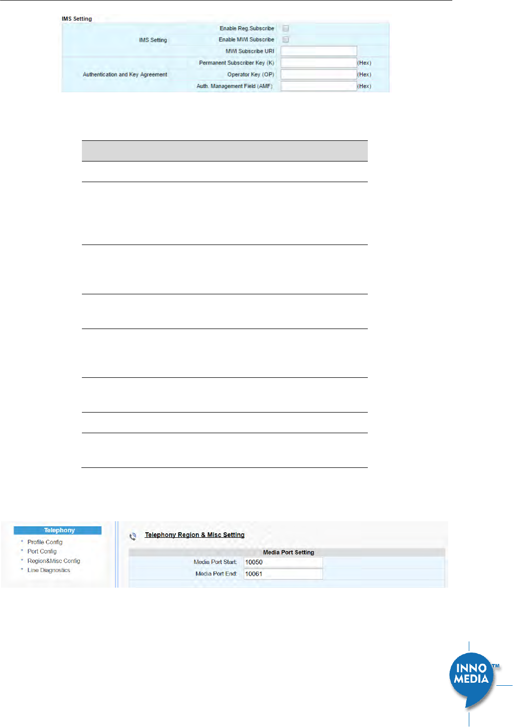
4.2.5 IMS related SIP settings
Only available on IMS firmware versions.
InnoMedia HG8328-1W Administrative Guide
Page 35
Copyright © 2019 InnoMedia. All rights reserved.
Figure 27. IMS Settings
IMS Setting
Description
IMS Setting
Enable Reg
Subscribe
The MTA subscribes to the registration
event, and responds to IMS server NOTIFY
messages which include AOR related
information in XML format.
Enable MWI
Subscribe
The MTA subscribes to the “Message
Waiting Indicator” event package, as defined
by 3GPP.
MWI Subscribe URI
Specify the URI of the message waiting
indicator subscription server.
Authentication
and Key
Agreement
Permanent
Subscriber Key (K)
ISIM specific service.
Operator Key (OP)
ISIM specific service
Auth. Management
Field (AMF)
ISIM specific service
4.3 Telephony Region and Misc Setting
Figure 28. Media Port Setting
4.3.1 Media Port Setting
Media port starting value should fall within the range 10 to 65535 and should be an even number. Care
should be taken as these settings can significantly impact voice performance or result in no voice path if
configured incorrectly. Consult your telephony service provider for configuration guidelines.
InnoMedia HG8328-1W Administrative Guide
Page 36
Copyright © 2019 InnoMedia. All rights reserved.
Field Name
Description
Media Port Start
The lowest RTP port number to be used
when sending RTP/RTCP traffic – It must be
an even number.
Media Port End
The highest RTP port number to be used
when sending RTP/RTCP traffic – It must be
an odd number.
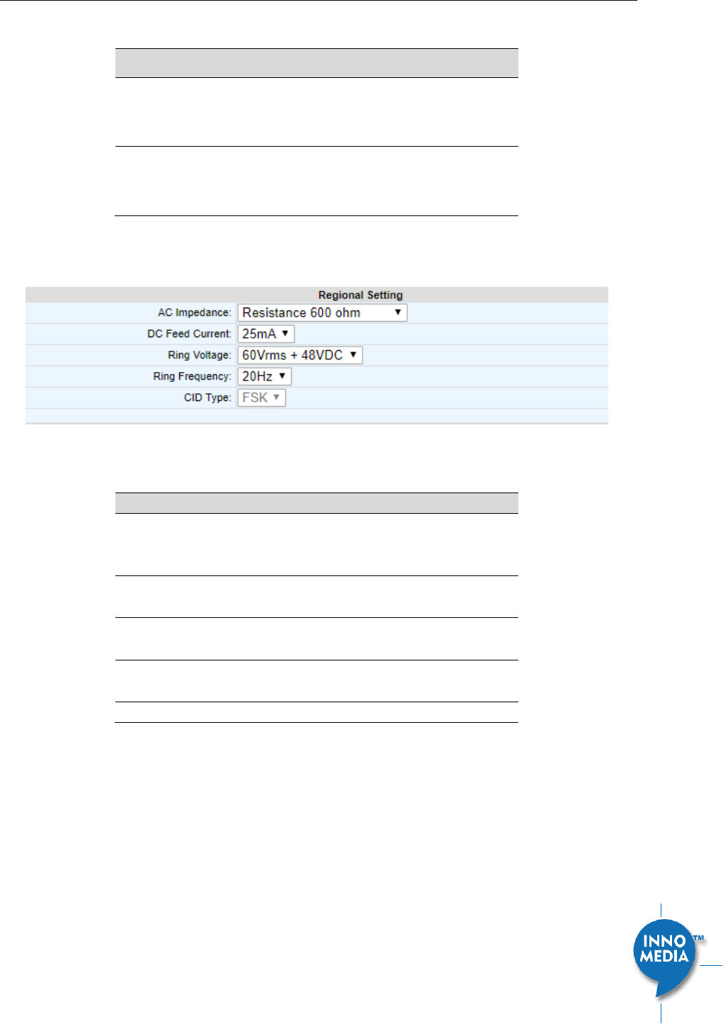
4.3.2 Regional Setting
Figure 29. Regional settings for power and analog line specifications
Field Name
Description (options available)
AC Impedance
Resistance 600 ohm
GR-57 900R+2.16uF
ETSI 270R+750R/150nF
DC Current Feed
25mA
40mA
Ring Voltage
60Vrms +48VDC
90Vrms Balanced
Ring Frequency
20Hz
25 Hz
CID Type
Support for FSK only
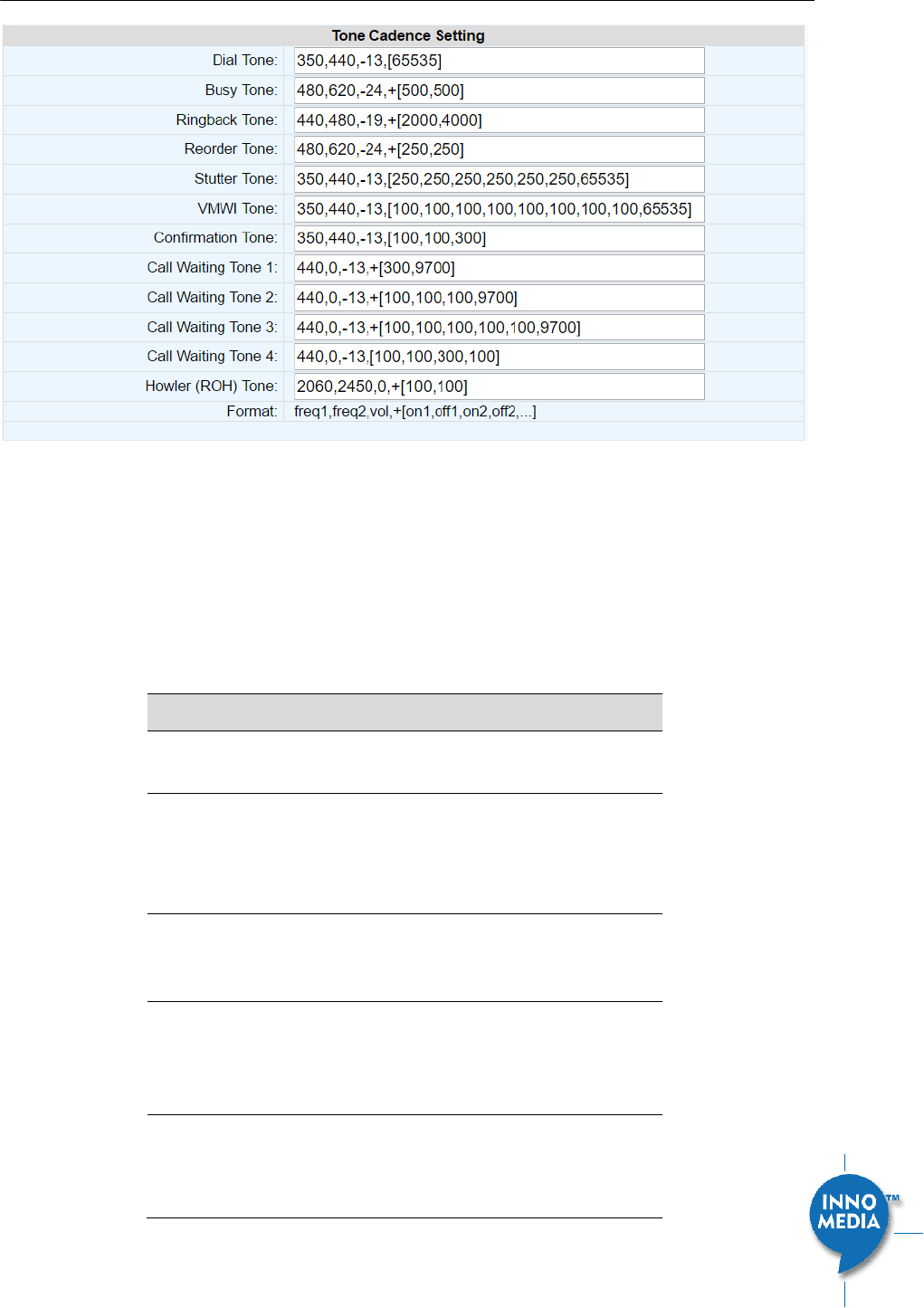
4.3.3 Tone Cadence Setting
Configures the tone cadence for an FXS port. When shipped from the factory, the MTA tone cadences are set
to match country requirements. You can manually set the tone cadence if you wish to override the default
country values.
InnoMedia HG8328-1W Administrative Guide
Page 37
Copyright © 2019 InnoMedia. All rights reserved.
Figure 30. Tone Cadence Setting
Tone Cadence Setting
Format – freq1, freq2,vol,+[on1,off1,on2,off2,…]
frequency 1, frequency 2, volume level in dBm
+ : loop the tone(s) forever
[ on1 duration in ms, off1 duration in ms…]. If the duration value is 65535, keep playing the last
tone.
Field Name
Description
Dial Tone
A dial tone indicates that the MTA is ready
to accept calls.
Busy Tone
A busy signal indicates a failure to complete
the requested call. Reasons could be:
The called number is occupied, or
The other party has hung up at the end
of a call.
Ringback Tone
A ring back tone (or ringing tone) is heard by
the caller while the phone they are calling is
being rung.
Reorder Tone
Reorder tone, also known as fast busy tone,
is the congestion tone or all trunks busy
tone of a PSTN network. It varies from
country to country.
Stutter Tone
A "stuttered" or interrupted dial tone is
often used to indicate a Calling feature such
as Call forwarding has been activated. (The
voice mail waiting tone is represented by
InnoMedia HG8328-1W Administrative Guide
Page 38
Copyright © 2019 InnoMedia. All rights reserved.
VMWI Tone below.)
VMWI Tone
Voice Mail Waiting Indication, indicating
that voice mail is waiting.
Confirmation Tone
Confirmation Tone is used to acknowledge
receipt for special services, such as:
Speed dialing, dial number has been
recorded.
Call forwarding activation and de-
activation, etc.
Call Waiting Tone
1-4
Call waiting tones are used for call waiting
conditions.
Howler (ROH) Tone
Receiver off hook tone
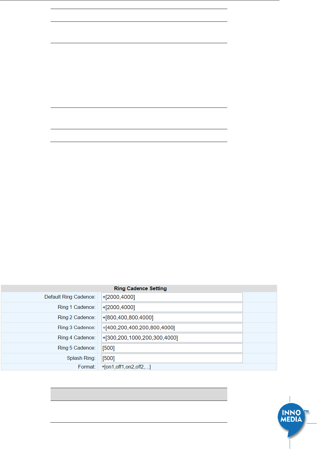
4.3.4 Ring Cadence Setting
For a telephone receiving an incoming call, ring cadence settings control the timing of the incoming ring-
signal. This varies from country to country and may consist, for instance, of the ring voltage being applied for
two seconds, followed by four seconds off, then back on for two seconds, and so on, until the phone is
answered or the calling party hangs up, or a maximum number of rings is reached. Note that HG8328-1W
supports multiple ring cadence profiles for different countries.
When shipped from the factory, the MTA’s ring cadence is set to match country requirements. You can
manually set the ring cadence if you wish to override the default country values.
Ring Cadence Setting (Format +[on1,off1,on2,off2,…])
+ : loop the tone(s) forever
[ on1 duration in ms, off1 duration in ms…]. If the duration value is 65535, keep playing the last
tone.
Figure 31. Ring Cadence Setting
Field Name
Description
Default Ring
Cadence
For a telephone receiving an incoming call,
the default timing pattern of the incoming
InnoMedia HG8328-1W Administrative Guide
Page 39
Copyright © 2019 InnoMedia. All rights reserved.
ring-signal.
Ring Cadence,
1-5
Different Ring Cadence settings for
distinctive rings.
Splash Ring
A short ring to notify that some specified call
features are processed. For instance, a short
ring (splash tone) can be used to notify each
time a call is forwarded.
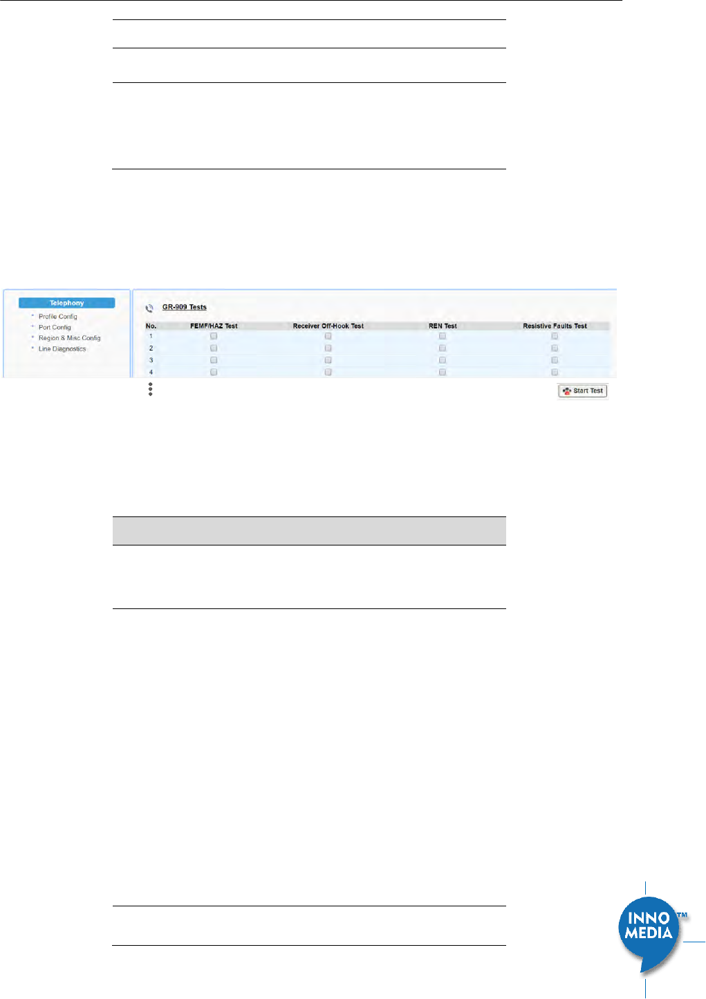
4.4 Line Diagnostics
4.4.1 GR909 Tests: triggered from the WEB Administrative Console
Figure 32. GR909 Test Line Test
HG8328-1W supports GR-909 test items which use a suite of standards-based electrical tests. Click all the
checkboxes for which GR909 confirmation is required. Then Click the <Start Test> button.
NOTE: If the Receiver is Off-hook, the REN Test and the Resistive Faults Test will show failures.
Field Name
Description
GR909 Line
Diagnostic Test
A suite of standards-based electrical tests
which detect physical problems with the
phone line.
FEMF/HAZ Test
This procedure tests for hazardous
electromotive force (HEMF) and foreign
electromotive force (FEMF) between the
TIP-GROUND and RING-GROUND leads. It
reports a failure if the following limits are
exceeded:
– Foreign DC HEMF limit = 135V.
– Foreign AC HEMF limit = 50Vrms.
– Foreign DC EMF limit = 6V.
– Foreign AC EMF limit = 10Vrms.
NOTE: Once this test is initiated and if a
failure is detected, the test will
automatically run periodically, e.g., every 30
sec till the foreign voltage is removed.
Receiver Off-Hook
This procedure discriminates between
resistive fault and a receiver off-hook

InnoMedia HG8328-1W Administrative Guide
Page 40
Copyright © 2019 InnoMedia. All rights reserved.
Test
condition by checking for a non-linear DC
resistance.
REN Test
This procedure measures REN (Ringer
Equivalence Number) loading by measuring
the load impedance at 20 Hz. An REN
loading of less than 0.175 REN or greater
than 5 REN is reported as a failure.
Resistive Faults
Test
This procedure measures TIP to RING on-
hook DC resistance. A DC resistance less
than 150 kΩ is reported as a failure.
4.4.2 GR909 Tests: triggered from SIP NOTIFY Message
The MTA supports server-initiated GR909 tests triggered by an incoming SIP NOTIFY Message with “Event:
gr909”. Example trace as follows:
NOTIFY sip:2148298788@172.16.0.119;user=phone SIP/2.0
Via: SIP/2.0/UDP 172.16.200.212:5060;branch=z9hG4bKac101ead5060-
76517495;rport
From: <sip:GR909@172.16.200.212>;tag=rebootapp_tag
To: <sip:2148298788@172.16.0.119;user=phone>
Event: gr909
Call-ID: 3-75ff0490-4bdccd8@ac101ead
CSeq: 1401 NOTIFY
Max-Forwards: 70
Contact: <sip:GR909@172.16.200.212>
Content-Length: 0
InnoMedia HG8328-1W Administrative Guide
Page 41
Copyright © 2019 InnoMedia. All rights reserved.
5 SYSTEM
5.1 Account Settings
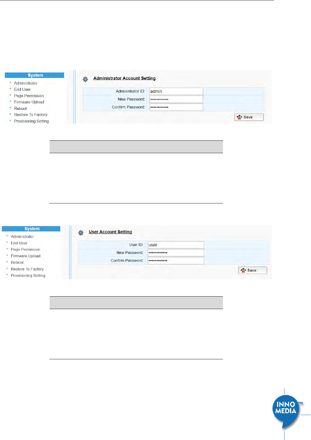
5.1.1 Administrator Account Setting
Figure 33. Administrator account setting
Field Name
Description
Administrator
Account Setting
This allows you to configure an
Administrator ID and Password.
Default ID is ‘admin’. Default Password is
‘password’. However, the default values are
service provider dependent.
5.1.2 End User Account Setting
Figure 34. User Account Setting
Field Name
Description
User Account
Setting
This allows you to configure a user’s user ID
and password.
Default ID is ‘user’. Default Password is
‘welcome’. However, the default values are
service provider dependent.
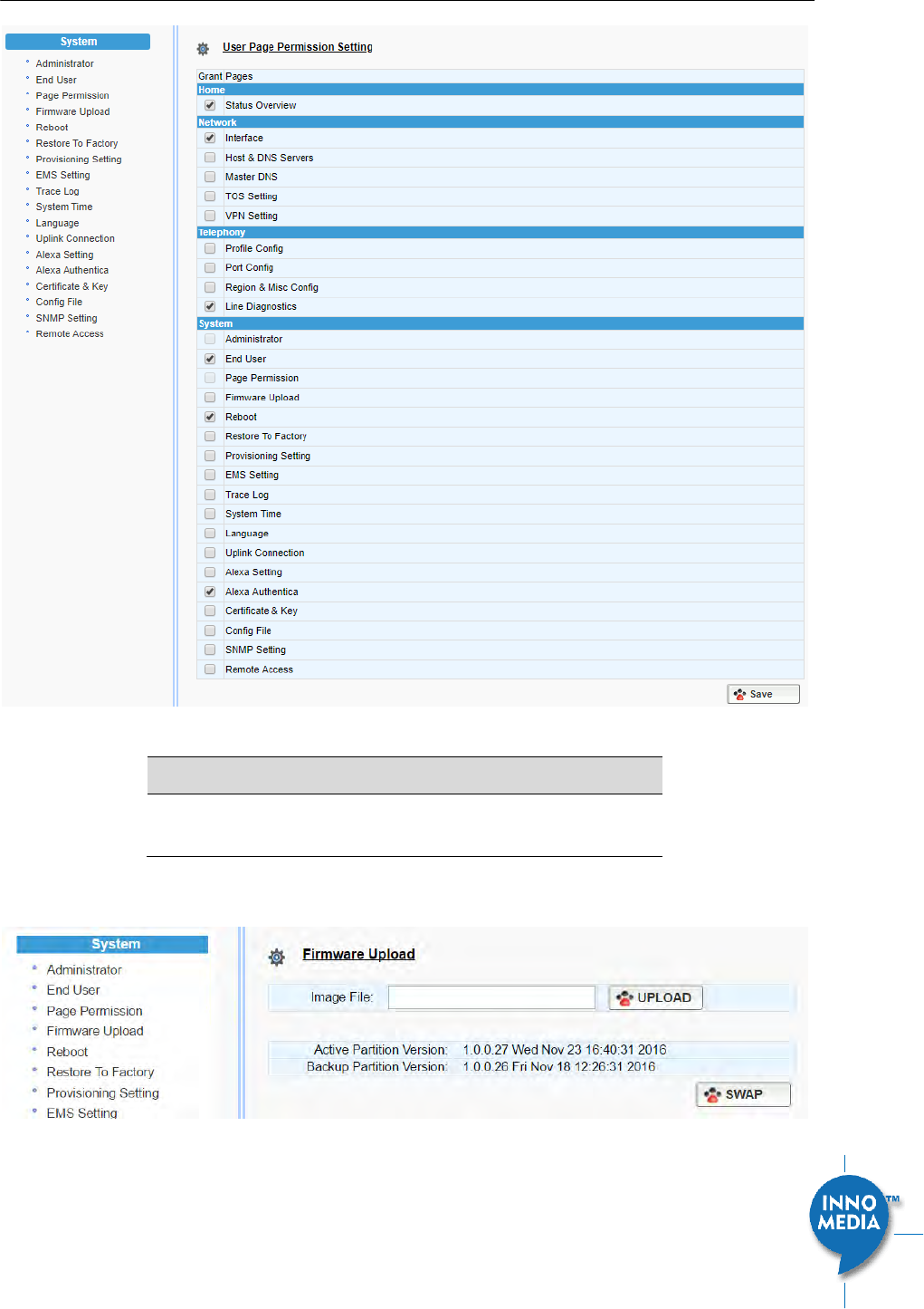
5.2 Page Permission
The administrator may specify which features are available for subscribers (ie users) to configure.
InnoMedia HG8328-1W Administrative Guide
Page 42
Copyright © 2019 InnoMedia. All rights reserved.
Figure 35. User Page Permission Setting
Field Name
Description
User Page
Permission Setting
Configure which pages the User Login
account can access.
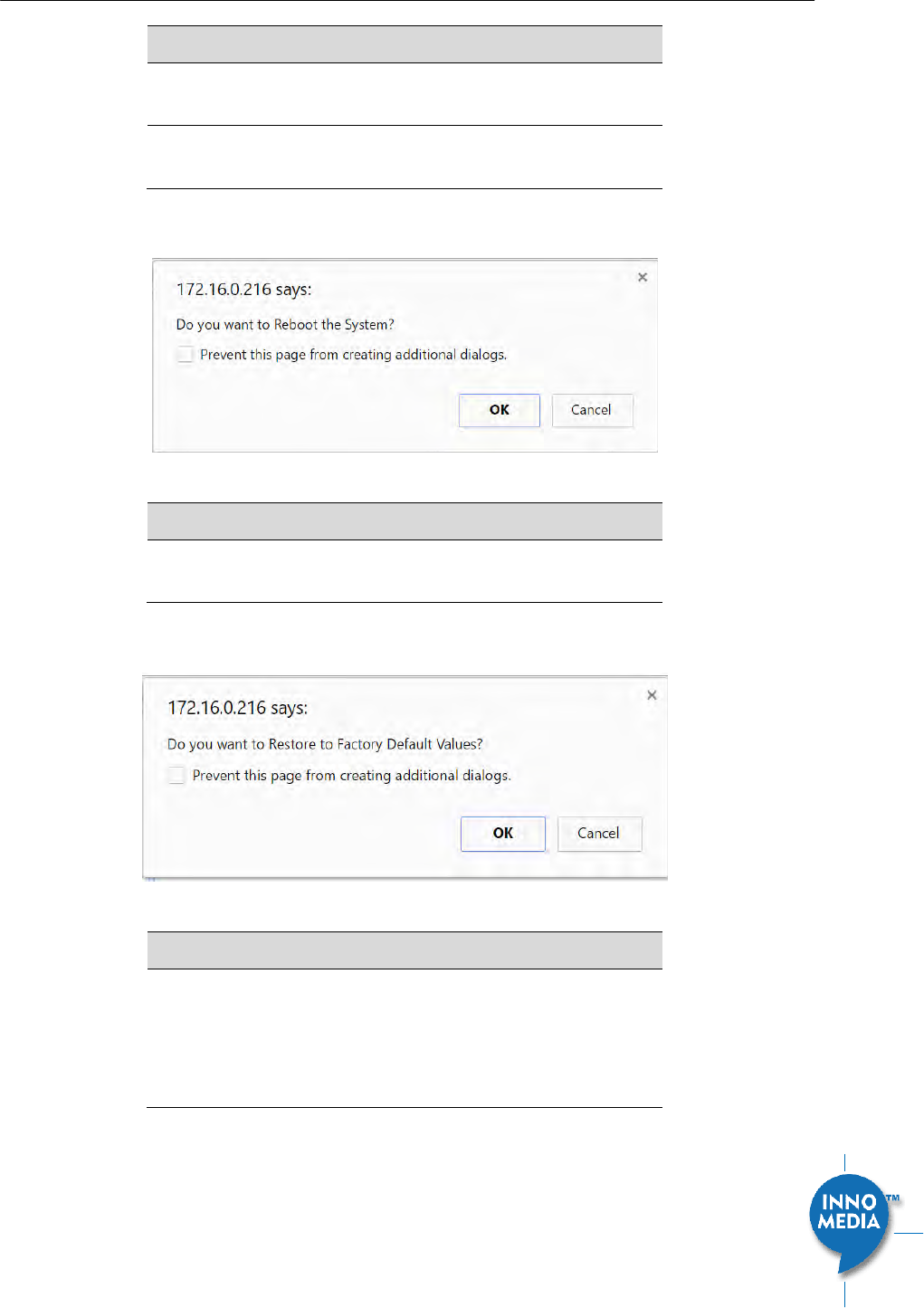
5.3 Firmware Upload
Figure 36. Firmware Upload
InnoMedia HG8328-1W Administrative Guide
Page 43
Copyright © 2019 InnoMedia. All rights reserved.
Field Name
Description
Firmware Upload
Browse to a new firmware image file to
upload to the unit.
SWAP
Click “SWAP” to switch the backup system
firmware to be active.
5.4 Reboot
Figure 37. Reboot Dialog
Field Name
Description
Reboot
Reboot opens a dialog box, and asks for a
confirmation to “Reboot the System”.
5.5 Restore To Factory
Figure 38. Restore To Factory Dialog
Field Name
Description
Restore To Factory
Opens a dialog box, and asks for a
confirmation to “Restore to Factory Default
Values”.
The factory default values are service
provider dependent.
InnoMedia HG8328-1W Administrative Guide
Page 44
Copyright © 2019 InnoMedia. All rights reserved.
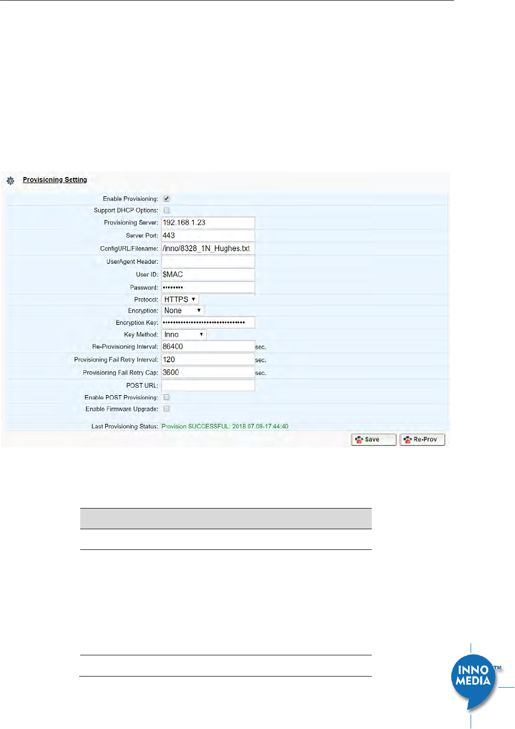
5.6 Provisioning Setting
5.6.1 Provision Server Setting
Provisioning Setting – Configure provisioning server and associated settings for this MTA device. Provisioning
is a powerful feature that allows you to automatically configure the unit with all of its parameters.
Therefore, if the unit is configured from the Factory with the desired Provisioning information, you will not
need to manually configure the MTA with its SIP Profile and User Information, since the desired information
can be entered into the Configuration File for that unit. Subsequently, when the device is powered on and
obtains its IP address, it will go to the provisioning server and be configured.
`
Figure 39. Provisioning Server Setting
Field Name
Description
Enable Provisioning
Turns provisioning on/off.
Support DHCP
Options
If enabled, the device will use the string
(including the provisioning server FQDN and
config file path) obtained from DHCP options
66 and 67 to compose the request URI for
provisioning. The request URI obtained from
the DHCP Options will override any manually
configured provisioning fields.
Provisioning Server
IP or FQDN of the Provisioning Server.

InnoMedia HG8328-1W Administrative Guide
Page 45
Copyright © 2019 InnoMedia. All rights reserved.
Server Port
Port to be used to connect to the
Provisioning Server.
ConfigURL/Filename
Specify the complete path and the config file
name to download.
UserAgent Header
User Agent Header sent out is modifiable.
Available parameters:
Model name ($MOD)
MAC ($MAC). The Ethernet WAN MAC
address is chosen as the device ID.
Version ($VER)
Config file last loaded ($CFG)
Example Syntax: $MOD $MAC $VER $CFG.
Output: MTA-8328-1E 001099112233
V1.0.0.0 /Provisioning/Config/xyz.cfg
User ID
The User ID used for HTTP, FTP, and HTTPS
authentication purposes
Password
The Password used for HTTP, FTP, and
HTTPS authentication purposes.
Protocol
The Protocol to connect to the server.
Supported protocols are: HTTP, HTTPS, FTP,
and TFTP.
Encryption
The Encryption Format of the config file to
be sent to the MTA. Supported formats are:
None, RC4, and AES-256.
Encryption Key
The encryption key to be used for
encryption. Below is a table of the number
of characters for each Encryption Type and
Key Method.
RC4
AES-256
Inno
32 chars
N/A
Openssl
32 chars
64 chars
Key Method
The following utilities (or approaches) can
be used to encrypt the provisioning config
file: Inno and Openssl.
Inno – InnoMedia proprietary hash key
encryption utility. This method can only be
applied when “RC4” is selected from the
Encryption menu. Provisioning config file
should be encrypted using the utility –
rc4_102 See Appendix A The use of
encryption key methods.
Openssl – the open source toolkit. This
method can be applied when either RC4 or

InnoMedia HG8328-1W Administrative Guide
Page 46
Copyright © 2019 InnoMedia. All rights reserved.
AES256 is selected from the Encryption menu.
Provisioning file should be encrypted using
Openssl.
Re-Provisioning
Interval
Time to next Re-Provision after a successful
Provision.
Provisioning Fail
Retry Interval
Provisioning Fail
Retry Cap
There are 2 associated timers:
Provisioning Fail Retry Interval : T1
Provisioning Fail Retry Cap: T2
If provisioning fails, the MTA initially retries
at T1 interval, and then doubles T1 each
time until it reaches T2, and then continues
at this interval until the system reboots or
there is a successful provisioning.
POST URL
Send HTTP POST messages to inform the
provisioning server of provisioning success
or failure. Enter the URL to which the MTA
sends HTTP POST messages.
Enable POST
Provisioning
Send HTTP POST messages to inform the
provisioning server of provisioning success
or failure. This setting only applies when
using InnoMedia’s EMS provisioning server.
Enable Firmware
Upgrade
When enabled, firmware will be
downloaded when a new version is
available. When disabled, firmware will not
download even if a new version is available.
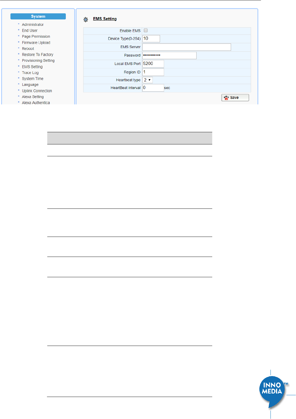
5.7 EMS Setting
5.7.1 EMS Server
The InnoMedia EMS server is a powerful provisioning and management platform for service providers to
perform device configuration/firmware management, to be able to see Call Statistics, Voice Quality
information, and to provide the ability to connect to devices behind NAT routers for diagnostics purposes.
InnoMedia HG8328-1W Administrative Guide
Page 47
Copyright © 2019 InnoMedia. All rights reserved.
Figure 40. Configuring EMS Server Information
Field Name
Description
Enable EMS
This enables the EMS feature.
Device Type (0-
254)
This is the device type configured on the
EMS Server, so that a user of the EMS server
will see the device by name (such as 8328-1)
in the device list. The type is also important
for what options/features will be seen when
a device is queried by the EMS.
EMS Server
The IP or FQDN address of the EMS Server
and port. Default is to use port 5200 for
connection to the EMS server.
Password
The authentication password to connect to
the EMS server.
Local EMS Port
The port number used at the MTA device in
order to connect to EMS server.
Region ID
The Region to which the device is assigned.
This is a number value that has to be
entered, so an example of region
configuration might be based on Area
Codes. Another example might be time
zones. When the EMS Server is set up,
careful consideration should be given to
how the regions are defined.
Heartbeat type
The MTA will send a heartbeat to the EMS
Server to let it know it is up and running. A
Data Tunnel between the EMS and MTA is
used, and this can be encrypted or not,
depending on the Option type chosen.
Below are the current Heartbeat types:

InnoMedia HG8328-1W Administrative Guide
Page 48
Copyright © 2019 InnoMedia. All rights reserved.
2 = Plain text tunnel formatted.
3 = Encrypted text using a shared secret key
4 = Plain text and carrying SIP registration
status
5= Encrypted text and carrying SIP
registration status
Heartbeat interval
The interval at which to send heartbeat
packets to the EMS server, in seconds. The
MTA uses this HB interval unless instructed
by EMS for a new HB interval
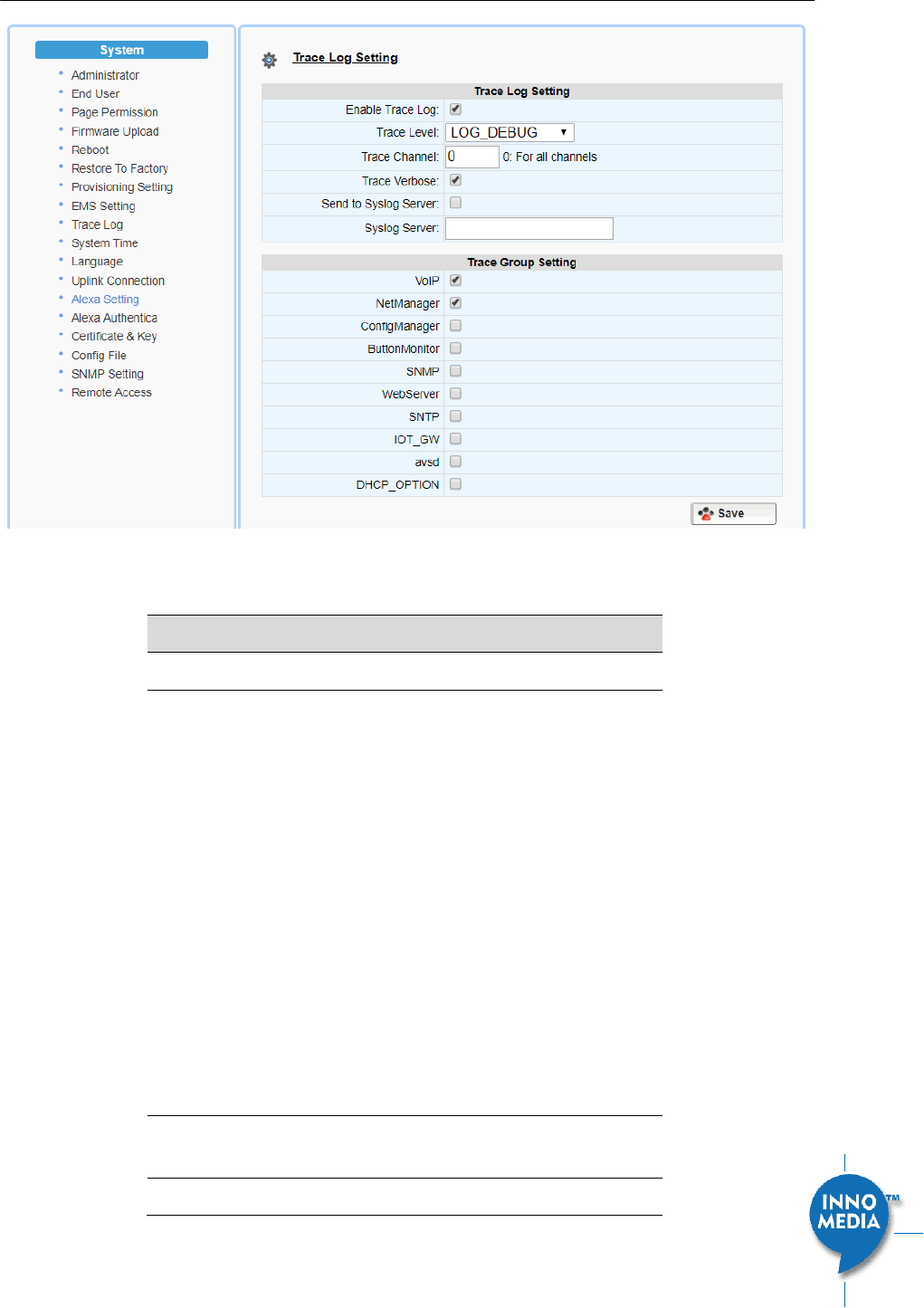
5.8 Trace Log
5.8.1 Trace Log Setting
Configure the MTA device to display debugging messages according to the trace level parameters. Note:
Trace Level “LOG_DEBUG” will have a significant performance impact on the MTA device. It is recommended
to use this feature only when debugging is needed.
An example is described as follows.
On WEB GUI:
1. Check “Enable Trace Log”
2. Trace Level menu, choose “LOG_DEBUG”
3. Check “Trace Verbose”
4. Configure “Trace Channel” to be “0” to monitor all ports of the system.
5. Check whatever items to be monitored from the “Trace Group Setting” table.
InnoMedia HG8328-1W Administrative Guide
Page 49
Copyright © 2019 InnoMedia. All rights reserved.
Figure 41. Trace Log Setting
Trace Log Setting
Description
Enable Trace Log
Enables the trace log.
Trace Level
Follows RFC5424 syslog message severities.
1 Alert: Action must be taken immediately
2 Critical: Critical conditions.
3 Error: Error conditions.
4 Warning: Warning conditions.
5 Notice: Normal but significant condition.
6 Informational: Informational messages.
7 Debug: Debug-level messages.
Additional Messages available:
LOG_STACK -- Network protocol related
messages.
LOG_DSP -- RTP traffic related messages.
Trace Channel
The ports (lines) you wish to monitor/debug.
0 covers all ports.
Trace Verbose
Enable Trace logs to be displayed in a Telnet

InnoMedia HG8328-1W Administrative Guide
Page 50
Copyright © 2019 InnoMedia. All rights reserved.
session.
Send to Syslog
Server
When checked, will send out messages to a
configured Syslog Server.
Syslog Server
Syslog server IP address or FQDN.
Trace Group
Setting
Description
Item list
Select items to monitor and display
associated messages. These messages can
be displayed on the CLI console or the
specified syslog server.
Note that some particular items will only be
displayed on the GUI when they are
enabled.
5.9 System Time
5.9.1 Time Setting
Configure the SNTP time server IP/FQDN and time zone with which the MTA device synchronizes. Accurate
time information is important for ensuring reliable telephony services.
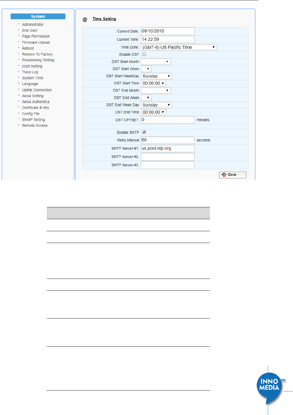
InnoMedia HG8328-1W Administrative Guide
Page 51
Copyright © 2019 InnoMedia. All rights reserved.
Figure 42. Time Setting
Field Name
Description
Current Date
The current date, which can be modified.
Current Time
The current time, which can be modified.
Time Zone
The current Time Zone configured, which
can be modified through the pull down list.
Note a reboot is needed for this setting to
become effective.
Enable DST
Enable or disable daylight saving time.
DST Start Month |
Week | WeekDay
|Time
Configure the DST starting date/time each
year.
DST End Month |
Week | WeekDay
|Time
Configure the DST ending date/time each
year.
DST Offset
Most of the regions where DST is deployed
have an offset of 60 minutes; however, a
few regions have an offset of 30 minutes.
Check the MTA deployment region for this
requirement.
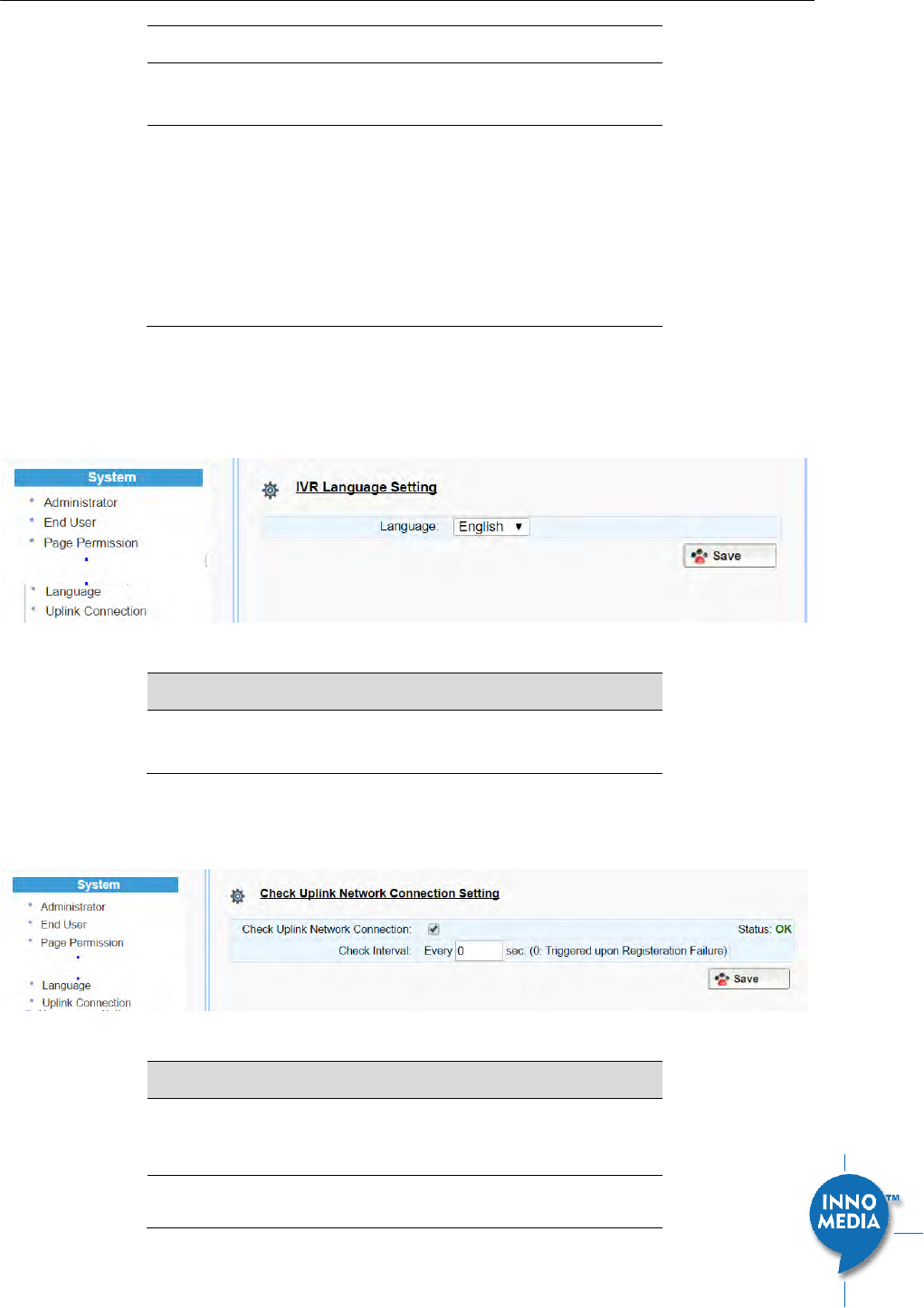
InnoMedia HG8328-1W Administrative Guide
Page 52
Copyright © 2019 InnoMedia. All rights reserved.
Enable SNTP
Enable the SNTP service.
Retry Interval
The time interval at which to synchronize
with the time server, in seconds.
SNTP Server #1, #2,
and #3
FQDN or IP of SNTP time servers to
synchronize with.
(Note: HG8328-1W tries all the configured
servers, and bases its calculation on RFC
2030 and the delay. It then uses the lowest
delay as the peer updates and sets the local
time.)
5.10 Language
The MTA device supports English, Spanish for Interactive Voice Response (IVR) services. Select the desired
language for your needs.
Figure 43. Language Selection for IVR system
Field Name
Description
IVR Language
Setting
The language of IVR announcements.
5.11 Uplink Connection
Figure 44. Uplink Detection Settings
Field Name
Description
Check Uplink
Network
Connection
Enable or disable the MTA to probe the
internet connection status.
Check Interval
How often device will send a ‘probe’
message out to determine whether the
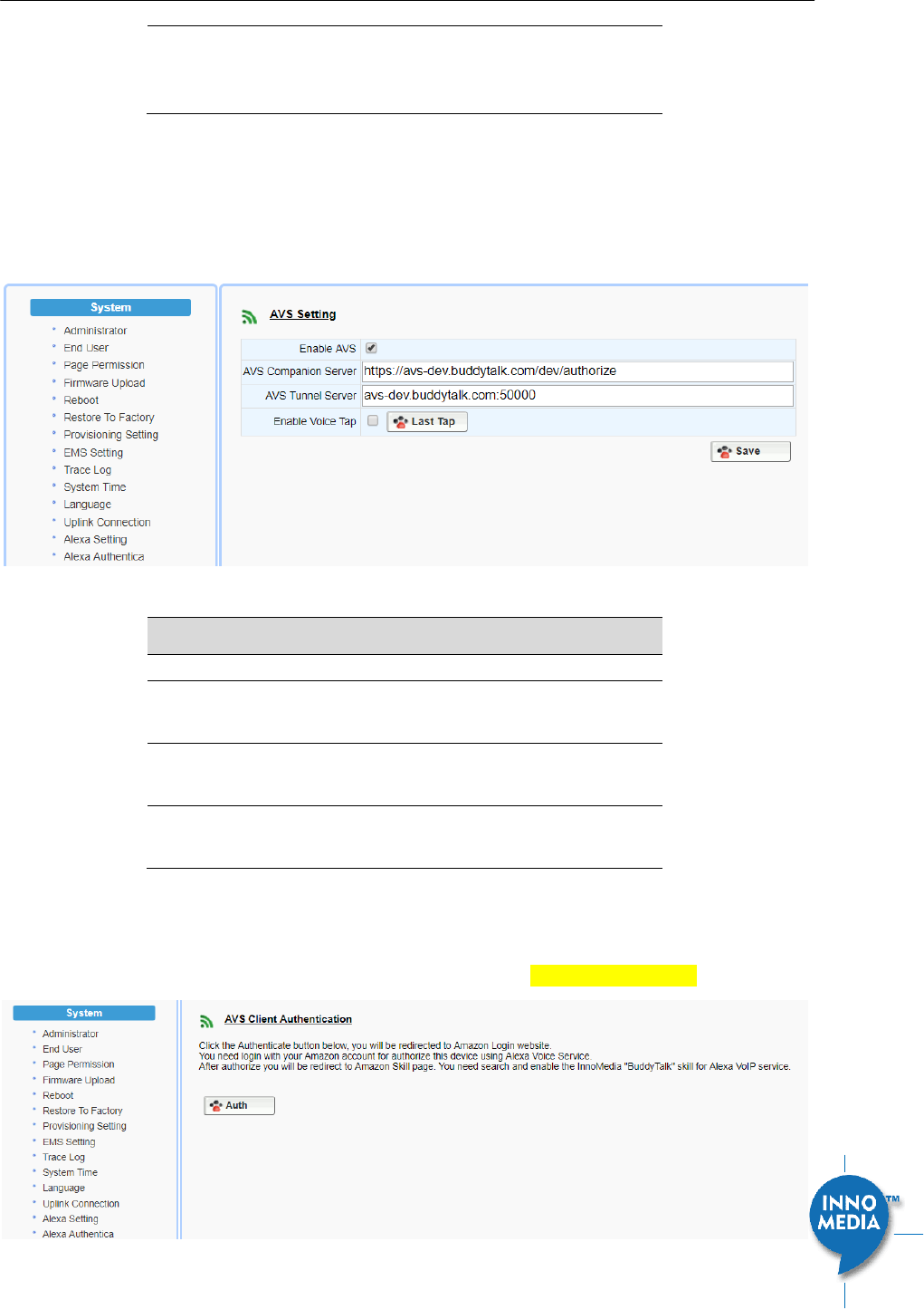
InnoMedia HG8328-1W Administrative Guide
Page 53
Copyright © 2019 InnoMedia. All rights reserved.
Internet connection is active. Set value to 0
to trigger ‘probe’ message being sent when
SIP registration fails.
5.12 Alexa Settings for BuddyTalk Services
Use the following screen to configure appropriate InnoMedia “InnoCloud” servers per instructions from
InnoMedia
for BuddyTalk service for the device.
Figure 45 Alexa setting
Field Name
Description
Enable AVS
Enable or disable the Alexa service.
AVS Companion
Server
Input the server FQDN as per instructions
provided by InnoMedia..
AVS Tunnel Server
Input the server FQDN as instructions per
instructions provided by InnoMedia..
Enable Voice Tap
Enable or disable the Tap (only for debug
capture purposes).
5.13 Alexa Authentication
User the following screen to authenticate the device and get authorized for BuddyTalk service.
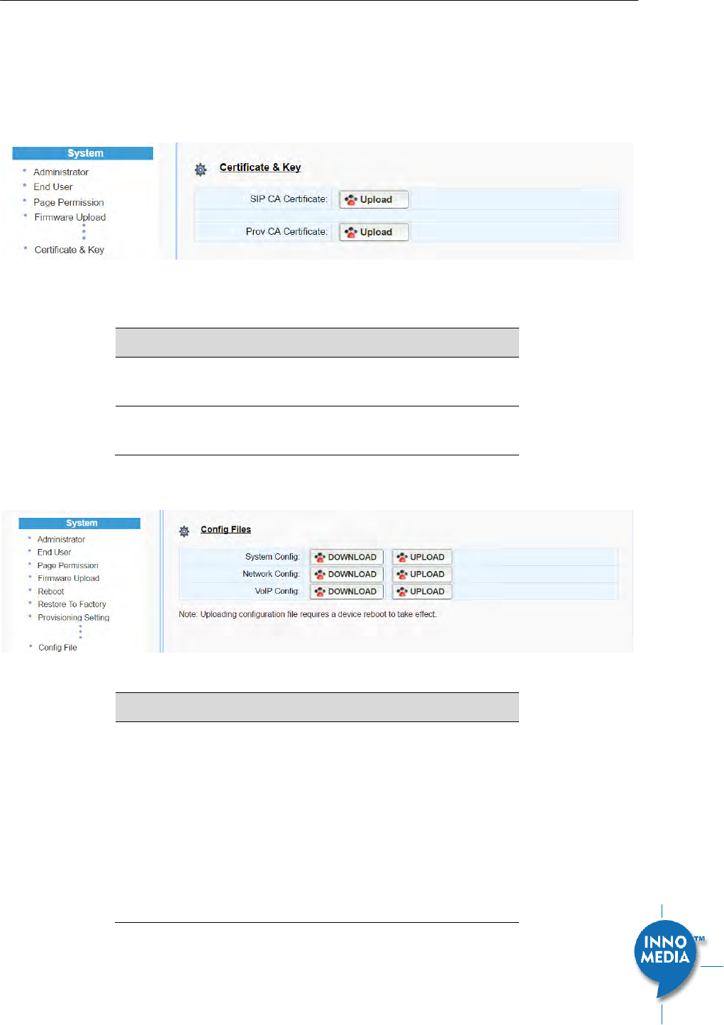
InnoMedia HG8328-1W Administrative Guide
Page 54
Copyright © 2019 InnoMedia. All rights reserved.
Figure 46 Alexa Authentication
5.14 Certificate & Key
This page allows you to upload the encrypted keys or certificate for transporting signaling data through a
secured TLS tunnel.
Figure 47. Certification & Key
Field Name
Description
SIP CA Certificate
Root certificate for verifying the SIP server
TLS Certificate.
Prov CA Certificate
Root certificate for verifying the Provisioning
server Certificate.
5.15 Config File
Figure 48. System Config
Field Name
Description
Config File
Upload: upload a config file to the MTA.
Download: Store the config file from the
MTA to a local drive.
System Config: settings from the “System”
category.
Network Config: settings from the
“Network” category.
VoIP Config: settings from the “Telephony”
category.
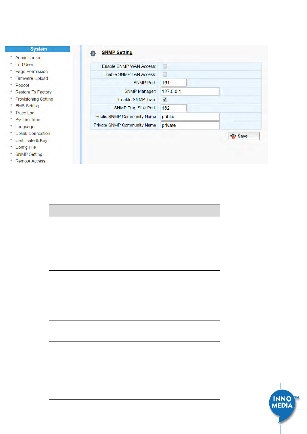
InnoMedia HG8328-1W Administrative Guide
Page 55
Copyright © 2019 InnoMedia. All rights reserved.
5.16 SNMP Setting
Configure the SNMP server information for the MTA to send traps to or to get commands from the SNMP
server.
Figure 49. SNMP Setting
Field Name
Description
Enable SNMP WAN
Access
Enable SNMP LAN
Access
Enable|Disable SNMP access from LAN or
WAN interface(s).
SNMP Port
The port for SNMP communications.
SNMP Manager
IP address or FQDN of the SNMP Manager
system.
Enable SNMP Trap
Enable|Disable sending traps to the SNMP
server. Refer to the HG8328-1W MIB file for
the list of supported traps.
SNMP Trap Sink
Port
Define an SNMP trap receiver.
Public SNMP
Community Name
Read only community string. This string is
used with an SNMP GET to access the MTA.
Private SNMP
Community Name
Read-write community string. This string is
used with an SNMP SET to set a certain
SNMP MIB variable (OID) to a specified
value.
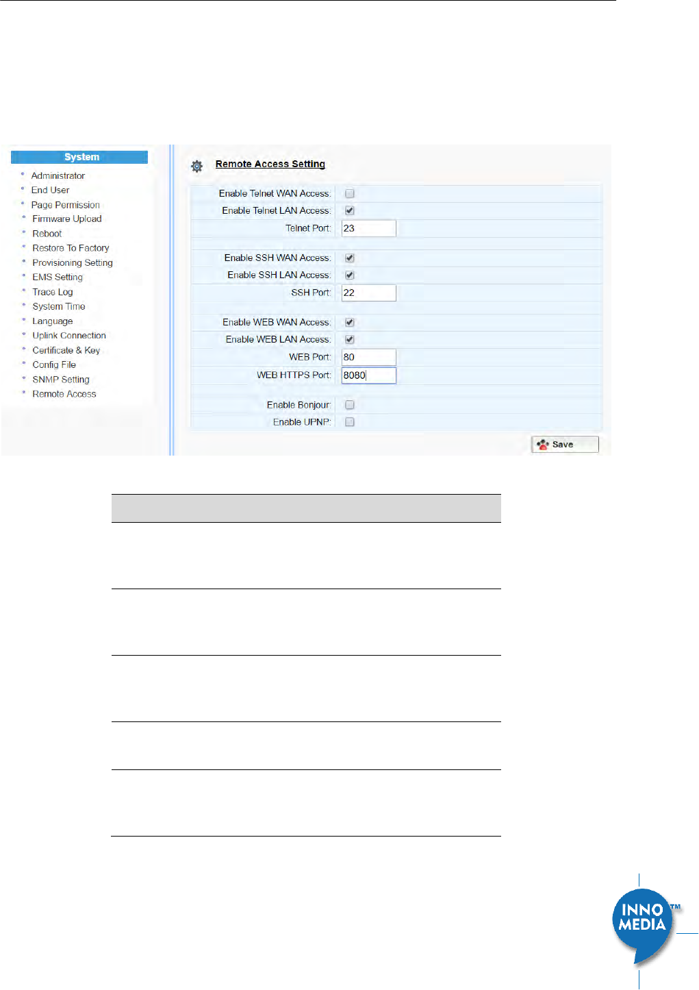
InnoMedia HG8328-1W Administrative Guide
Page 56
Copyright © 2019 InnoMedia. All rights reserved.
5.17 Remote Access
5.17.1 Remote Access Setting
Configure the designated protocols and ports for a system to access the MTA device remotely.
Figure 50. Protocol and Port Settings for Remote Access
Field Name
Description
Telnet WAN|LAN
Access
Enable/Disable WAN/LAN access via Telnet
and configure what port Telnet will be
allowed to use.
SSH WAN|LAN
Access
Enable/Disable WAN/LAN access via SSH and
configure what port SSH will be allowed to
use.
WEB WAN|LAN
Access
Enable/Disable WAN/LAN access via HTTP or
HTTPS and configure what ports will be used
for each.
Bonjour
Enable Bonjour – allows Apple devices to
discover the HG8328-1W on the network.
UPnP
Enable UPnP – allows devices which
supports UPnP to discover the HG8328-1W
on the network.

InnoMedia HG8328-1W Administrative Guide
Page 57
Copyright © 2019 InnoMedia. All rights reserved.
6 CLI COMMAND REFERENCES
Only the Administrator user is allowed to access the HG CLI console. The login ID and password are identical
to those for WEB console login. The CLI command hierarchy is designed similarly to that of the WEB console.
Once logged in successfully, the command menu is displayed.
[v]voip VoIP Configuration
[n]net Network Configuration
[s]system System
[f]factory Factory
[d]restore Restore to Default Setting
Type the char enclosed in the square bracket [] to enter that particular section.
Type question mark “?” at any level to display available commands.
Type “cd ..” to go back to the upper level.
[f] factory sub-menu is password protected.
Type command “save” or “write” whenever the MTA configurations being updated through CLI
commands.
Under any level, to show debug messages on the CLI console, type “debug on”; to stop debug messages
being displayed, simply type “debug off”.

InnoMedia HG8328-1W Administrative Guide
Page 58
Copyright © 2019 InnoMedia. All rights reserved.
Appendix A The use of encryption key methods
Inno rc4_102
Use utility “rc4_102” to encrypt the plaintext config file (e.g., MTA6328_$MAC.cfg) with a 32-char-long key.
Syntax:
rc4_102 mac key input-file ['out-prefix'] [logfile]
Example:
rc4_102 001099001122 1234567890qwertyuiop1234567890as
MTA_sample_config.txt MTA
Output:
Encrypted config file: MTA001099001122.cfg is created.
Openssl command example
Provisioning config file should be encrypted using the following command at the provisioning server when
AES-256 is selected from the encryption menu.
$ openssl enc –aes-256-cbc –k password –in infile –out outfile

InnoMedia HG8328-1W Administrative Guide
Page 59
Copyright © 2019 InnoMedia. All rights reserved.
Appendix B InnoMedia Contact
InnoMedia Incorporated
1901 McCarthy Boulevard
Milpitas, CA 95035
U.S.A
Phone: 1-408-432-5400
Fax: 1-408-943-8604
www.innomedia.com
Technical support email: techNA@innomedia.com
<End of Document>