INOVA Geophysical Equipment FSU2E FSU-2E User Manual FFFieldOperations Content
INOVA Geophysical Equipment Limited FSU-2E FFFieldOperations Content
Contents
- 1. Users Manual
- 2. Operations content
Operations content

FireFly Field Operations Quick Reference Guide 1
Contents
Equipment Layout
Changing the External Battery
Field Shooting for Dynamite
Equipment Pickup

FireFly Field Operations Quick Reference Guide 2
Equipment Layout
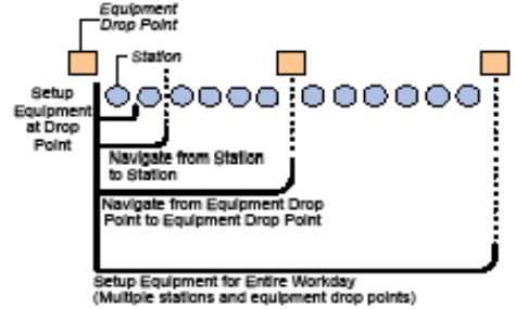
The basic workflow for equipment layout is:
• Set up the equipment at the equipment drop point
• Navigate from station to station, with an equipment drop point at specified intervals
• Navigate from station to station
Equipment
A set of FireFly station equipment consists of:
• Field Station Unit (FSU2E)
• VectorSeis sensor (SVSM)
• External Battery
Note Do not connect the equipment until you are at the station.
The following example uses six stations per equipment drop point:
FireFly Field Operations Quick Reference Guide 3
Figure 1-1. Equipment Layout Example
TASK: Lay Out Equipment
1. Locate station equipment.
Use NavTool to locate the equipment drop point and move equipment to the closest station location.
2. Unload equipment.
• Unload the first set of the FireFly equipment.
FireFly Field Operations Quick Reference Guide 4
• Attach the antenna to the antenna mount.
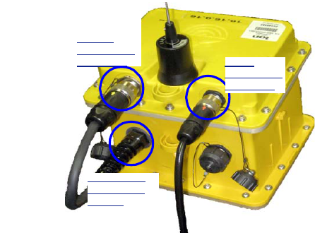
• Plug the VectorSeis cable into the FSU2E.
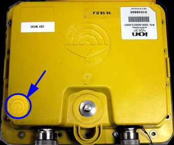
• Plug the external battery into the FSU2E as shown and swipe the magnet over the FSU2E power symbol to turn on
the FSU2E.
FireFly Field Operations Quick Reference Guide 5
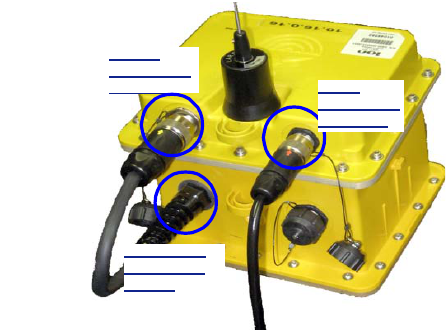
Figure 1-2. FSU2E connections
Caution To prevent damage to the FSU2E, you must connect the VectorSeis sensor to the FSU2E before connecting the
external battery to the FSU2E.
SVSM
Connection
on FSU2E
Battery
Connection
on FSU2E
Connection
on External
Battery
FireFly Field Operations Quick Reference Guide 6
Figure 1-3. FSU2E Magnet Swipe Area
3. Place FSU2E and VectorSeis sensor.
• Using NavTool, determine the proper location for the VectorSeis sensor.
• Auger a hole for the VectorSeis sensor and place the sensor securely in the hole.
• Using NavTool, perform these steps:
a. Select the battery type that you have connected to the FSU2E.
b. Select the sensor orientation.
FireFly Field Operations Quick Reference Guide 7
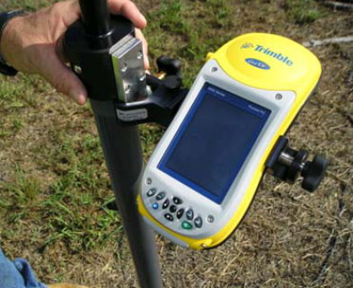
4. Take alignment readings.
• Keeping the NavTool attached to the Alignment pole, place the Alignment pole over the VectorSeis sensor to get a
reading.
Figure 1-4. NavTool on Alignment Pole
• Using NavTool, perform these steps:
FireFly Field Operations Quick Reference Guide 8
a. Select the FSU2E that you are connecting to.
b. After the NavTool runs FSU2E tests, transmit the data to the FSU2E.
c. Take a GPS and Compass reading with NavTool and transmit the readings to FSU2E.
5. Move to the next station.
• Pick up equipment and drill and move to the next station.
• Navigate to the next location using NavTool.
6. Unload equipment.
• Unload the next set of FireFly equipment (FSU2E, VectorSeis unit, and external battery) and place the units at the
station location.
• Plug the VectorSeis sensor cable, the antenna, and the external battery into the FSU2E. Wait 30 seconds after
plugging battery into the FSU2E to place the FSU2E and VectorSeis sensor.
Note Connect the components in this order:
Sensor, Antenna, Power battery (SAP)
7. Repeat step 3 and step 4 for all remaining stations.
8. Move to final station.
• Secure the empty equipment at the final station in the set.
• Use NavTool to take the GPS reading for the empty equipment drop point position.
FireFly Field Operations Quick Reference Guide 9
9. Use NavTool to select the next equipment drop point in the field and repeat step 1 to step 9.

FireFly Field Operations Quick Reference Guide 10
Changing the External Battery
You can change out an external battery in the field.
Caution The batteries should be replaced while the CRUs are operational and transmitting to the FSU2Es. If the CRUs are
not running, the FSU2Es may lose the timing reference and waste battery power.
Equipment
Uses the following equipment
• Charged external battery and cable
• NavTool
• Magnet
1. Navigate to station location where the battery needs to be changed.
2. Unplug the external battery from the FSU2E.
3. Plug the new battery into the FSU2E. The FSU2E will reboot when the battery is attached.
4. If the FSU2E does not reboot, power on the FSU2E by swiping with magnet.
5. Verify that the NavTool connects to the FSU2E.
6. Using NavTool, troubleshoot and select the battery to replace.
FireFly Field Operations Quick Reference Guide 11
7. Return the discharged to the Battery Charging Module for checking and recharging.
Figure 1-5. FSU2E connections
SVSM
Connection
on FSU2E
Battery
Connection
on FSU2E
Connection
on External
Battery

FireFly Field Operations Quick Reference Guide 12
Field Shooting for Dynamite
Crew and Equipment
A crew of two:
• Shooter
• Helper
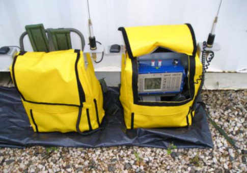
The following FireFly equipment is used:
• Pelton Shot Pro® II firing pack (includes all Pelton equipment)
• digital compass mounted to firing pack
• NavTool
• Radio
• Backpack with firing line and uphole phone
Note The total number of shooting crews will vary depending on the daily production targets, resources and equipment.
The communication collision management allows shooting crews to operate independently and in parallel so a higher
number of total crews can operate simultaneously, compared to traditional dynamite shooting operations.
FireFly Field Operations Quick Reference Guide 13
TASK: Shooting
Please refer to the Shot Pro II Manual for detailed information about using the Shot Pro.
Figure 1-6. Pelton Shot Pro
1. Navigate to the source position using NavTool and take a GPS reading (S & H1).
2. Prepare for shooting (S & H1).
FireFly Field Operations Quick Reference Guide 14
• (H1 only) Connect the firing line to the cap lead at the shot hole.
• Place the uphole geophone beside the shooting position so that the uphole time of the shot can be measured.
• Stretch out the firing line and the geophone line while moving a safe distance (typically a minimum of 100 feet) from
this source position in the direction of the next source position, if possible.
• Remove the Shot Pro backpack and place it upright on the ground. Place NavTool on top of shooting pack (the
NavTool shows status during shooting and is used for data entry).
3. Prepare for shooting (S).
• Press the READY button and wait for the ARM notification from the recorder.
• When the ARM notification is received (green LEDs flash on the Shot Pro front panel and the NavTool displays a
message), press and hold the two firing buttons on the Shot Pro to charge the firing voltage and arm the Shot Pro.
Continue holding the buttons until the FIRE command is received.
FireFly Field Operations Quick Reference Guide 15
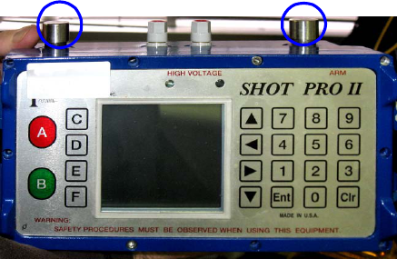
Figure 1-7. Shot Pro II Firing Buttons
Warning At this point, the shooter has control over the shot
detonating. If the area around the shot hole is not clear, the shooter can release the buttons to abort the shot.
4. Take the Shot (S).
• When the FIRE command is received and the shot is detonated, release the charge buttons.
• Select the shot status (good, misfire, or blow out) on the NavTool before moving to the next shot point.
FireFly Field Operations Quick Reference Guide 16
• If the shot was a misfire, retry the shot. It is not necessary to radio the mis-fire into the recorder over voice radio.
The system automatically puts the shooter back into the shooting queue to try the shot again.
5. Clean up and navigate to next position (S&H1)
• (H1) Clean up the detonated shot hole.
• (S) Put the Shot Pro backpack on and use NavTool to go to the next position.
6. Repeat step 2 through step 5 for all assigned source positions for the day.

FireFly Field Operations Quick Reference Guide 17
Equipment Pickup
The basic workflow for equipment pickup is:
• Navigate to the first station
• Verify the equipment
• Pick up the equipment
• Navigate to the next station
• Package equipment at the equipment pickup point for pickup
Equipment
A set of FireFly station equipment consists of:
• Field Station Unit (FSU2E)
• VectorSeis sensor (SVSM)
• External Battery
TASK: Pick Up Equipment
1. Navigate to first station.
FireFly Field Operations Quick Reference Guide 18
2. Pick up FSU2E, SVSM, and battery.
• Swipe the FSU2E with a magnet to wake it up.
• Using NavTool, perform these steps:
• Connect to the FSU2E.
• Verify the ID of the FSU2E.
• If the ID is correct, click Picked Up.
3. Pick up the equipment.
• Retrieve VectorSeis sensor, using extraction tool if necessary.
• Disconnect the external battery from the FSU2E.
• Disconnect the VectorSeis sensor from the FSU2E.
• Gather the FSU2E, VectorSeis sensor, and external battery.
Caution To prevent potential problems, disconnect the battery from the FSU2E before disconnecting the VectorSeis Sensor
from the FSU2E.
4. Navigate to next position and repeat step 2 and 3.
5. Move to the last station.
• Ensure that all ground assembly equipment has been collected.
• Secure the equipment at equipment pickup point for pickup by helicopter or vehicle.
FireFly Field Operations Quick Reference Guide 19
• Use NavTool to take GPS reading for the equipment pickup point.
6. Use NavTool to select next set of stations in the field and repeat step 1 to step 5.