INTO TECH SPLUS DVR BOARD User Manual users manual 1
INTO-TECH Inc. DVR BOARD users manual 1
UserManual.wiki
>
INTO TECH
>
SPLUS User Manual
>
users manual 1
Contents
1.
users manual 1
2.
users manual 2
users manual 1
Navigation menu
Upload a User Manual
Namespaces
Wiki Guide
HTML
PDF
Info
Views
User Manual
Discussion / Help
Navigation
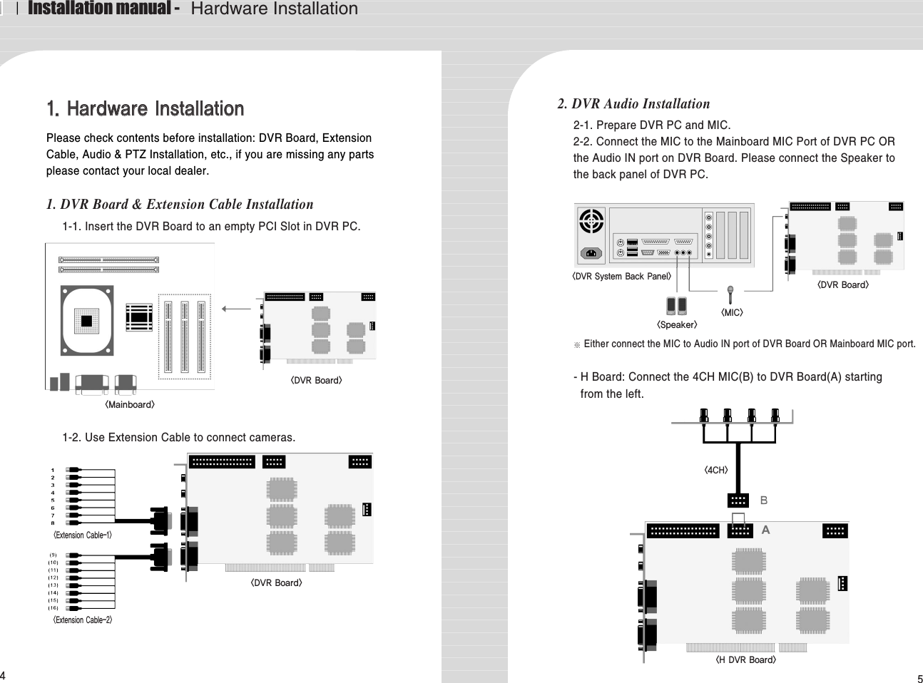
![89To use 16 port In/Out, A : Slave Board must remove jumper. B : Master Board must install jumper.< 16 port In/Out Connection>5. I/O Board Installation5-1. Prepare Sensor, Alarm, I/O Board and I/O Extension Board for I/OBoard Installation. A : Industrial Case System can use In/Out port separately when additionalBack Panel is available.< 8 port In/Out Connection>I/O Extension Board <DVR Board><I/O Board><I/O Slave Board><I/O Master Board>4CH Input3CH OutputAAB4CH Input5CH OutputⅠInstallation manual - Software Installation1. Software InstallationYou can install SmartDVR Software by using SmartDVR Formula CDor downloading from INTOTECH website, www.intotech.co.kr.Software CD consists of Server Package (Main program, WebClientprogram, Apache HTTP Server program), Client Package (NetClientprogram) & AVI Codec. User Manual is also available from SW CD.[Main Program Installation]Insert SmartDVR Formula CD into CD-ROM drive or runDvrSetup.exe file; the following installation screen will appear .Click the icon below and Main Program installation willautomatically proceed.Installation Step : Apache HTTP Server (Web Server) ->WebClient -> SmartDVR Formula](https://usermanual.wiki/INTO-TECH/SPLUS.users-manual-1/User-Guide-532349-Page-2.png)
![ⅠInstallation manual - Software Installation10 111. SmartDVR Apache HTTP Server (Web Server) Installation1-1 Installation wizard tool will appear. Click [Next].1-2 Read the License Agreement and if you agree to thecontents, select [I accept…] and click [Next].1-3 Click [Next] after checking server information of ApacheHTTP Server.1-4 Insert Network Domain, Server Name, Administrator’sE-mail Address.(This procedure is only a formality. In general cases, follow example)Select [Run as a service for All Users – Recommended]and click [Next].](https://usermanual.wiki/INTO-TECH/SPLUS.users-manual-1/User-Guide-532349-Page-3.png)
![ⅠInstallation manual - Software Installation12 131-5 Select Setup Type as [Complete] and click [Next].1-6 Click [Next] without change of setting. Note: Do not changethe directory!1-7 After the setting is finished, click [Install] and start installation.1-8 After the installation is done, click [Finish].](https://usermanual.wiki/INTO-TECH/SPLUS.users-manual-1/User-Guide-532349-Page-4.png)
![ⅠInstallation manual - Software Installation14 151-9 After the installation is finished, a message confirming thechange of the Server port of Apache will appear.2 SmartDVR WebClient Installation2-1 After the Installation Wizard Tool is appeared, click [Next].2-2 Check the contents of License Agreement; if you agree to thecontents, click [Yes]. 2-3 After the installation is done, click [Finish].](https://usermanual.wiki/INTO-TECH/SPLUS.users-manual-1/User-Guide-532349-Page-5.png)
![ⅠInstallation manual - Software Installation16 173 SmartDVR Formula Installation3-1 After Installation Wizard Tool is appeared, Click [Next].3-2 Check the details of License Agreement; if you agree to thecontents, click [Yes].3-3 After choosing [Destination Folder] for installation, click[Next]. 3-4 After the installation is done, click [Finish].](https://usermanual.wiki/INTO-TECH/SPLUS.users-manual-1/User-Guide-532349-Page-6.png)
![ⅠInstallation manual - Software Installation193-5 Driver Installation: Wizard automatically installs driversaccording to each board type.3-6 Reboot PC after all the installation.4. SmartDVR Formula Uninstallation4-1 Goto [Start] – [Control panel] and click [Add/RemoveProgram].4-2 Select [SmartDVR Formula] and click [Change/Remove].Click the icon below and NetClient Program installation will proceed.5 NetClient Installation5-1 After the Installation Wizard Tool is appeared, click [Next].5-2 After choosing [Destination Folder] for installation, click [Next].18](https://usermanual.wiki/INTO-TECH/SPLUS.users-manual-1/User-Guide-532349-Page-7.png)
![ⅠInstallation manual - Software Installation20 215-3 After the installation is finished, click [Finish]6 NetClient Uninstallation6-1 Goto [Start] – [Control panel] and click [Add/RemoveProgram].6-2 Select [NetClient Plus] and click [Change/Remove].AVI Codec InstallationClick the icon below and AVI Codec installation will proceed.7-1 AVI Codec Installation diagram.7-2 After the installation is finished, click [Finish].](https://usermanual.wiki/INTO-TECH/SPLUS.users-manual-1/User-Guide-532349-Page-8.png)
![22 23ⅡUser Manual - Main Program3 Main Program01. Main ProgramMain Program enables users to monitor images through PC monitor.The main program supports the following functions: record images,search & playback images and control camera remotely. Image canalso be transmitted over the network to any remote site. <Main Program>1 : Control Panel2 : Screen Partition Panel3 : Pan/Tilt Control Panel4 : Camera Selection Panel5 : Audio Volume Control Bar6 : Status Information Panel1-1 Control PanelControl Panel consists of the following icons: This enables usersto run search programs, manually record images and openconfiguration window. - Search Icon: Search Option.- Configuration Icon: To change setup of program.- Lock Icon: Supports password lock function for Serversecurity.- Recording Icon and All Icon: Record only certain channels – Enable users to manuallyselect certain channels for recording.Record all channels – Click [All] icon and click [REC] iconto record all channels.→Search Icon→Lock IconConfiguration ←IconRecording Icon ←→All Icon→❶→❷→❸❺❹❻1-3 Pan/Tilt Control PanelUse of Pan/Tilt Camera, 1.Select correct [Receiver] protocol from[Configuration].2. Select the channel which is connectedto Pan/Tilt camera.3. Click various buttons from Pan/TiltControl Panel to control camera.(Pan/Tilt/Zoom/Focus).1-2 Screen Partition PanelSupport 7 kinds of various screenpartitions, full-screen and sequencerotation display mode etc. [Screen Partition Panel]Pan/Tilt& Zoom/FocusButton](https://usermanual.wiki/INTO-TECH/SPLUS.users-manual-1/User-Guide-532349-Page-9.png)
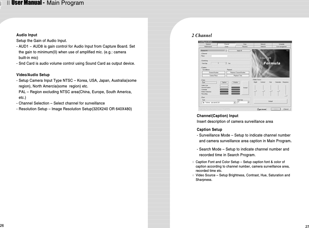
![24 251-5 Audio Volume Control BarIf Audio input is configured from[Configuration] - [General], audio volumecan be controlled from Audio VolumeControl Bar. 2 ConfigurationConfiguration Folder consists of [General], [Channel], [Store],[Network], [Schedule], [Maintenance], [Event], [Receiver], [VideoOut] and [User Management] sub-panels. Configuration is usedfor setting Resolution, Image Quality, Motion Detected Recording,I/O, Schedule, Pan/Tilt Receiver Protocol, Network IP setup, etc.Disk Full1-4 Camera Selection PanelClick specific channel from CameraSelection Panel to enlarge and viewimages.1-6 Status Information PanelIndicates number of connection fromInternet( T C P ) & modem. Disk Full will be indicated in red colorif there is no space left in HDD. Start Section- Auto Start: DVR program automatically executed when systemis turned on.- Max size at starting: DVR Program is setup as the exact size ofmonitor resolution to prevent display of other programs. Exit SectionOption: Only DVR program shuts down after closing DVRProgram OR the complete system shuts down.(Computer Power OFF). ⅡUser Manual - Main ProgramInternet(TCP) Conection CH No.Modem Conection CH No.1-1 General](https://usermanual.wiki/INTO-TECH/SPLUS.users-manual-1/User-Guide-532349-Page-10.png)
![ⅠInstallation manual - Hardware Installation4. Real Display(RD) Board Installation4-1. Insert the Real Display Board into an empty PCI Slot in DVR PC. 4-2. Use Cable to connect Real Display Board with DVR Board. Real Display Board cannot be used alone, it must be used with S, H, HPLUSDVR Boards.67AB3. P/T/Z Installation3-1. P/T/Z Cable [A] Cable : Connect to COM port of DVR PC[B] Cable : Connect to DVR Board[C] Cable : Connect to Receiver Cable- HP Board: Connect the 8CH MIC(B) to DVR Board(A) startingfrom the top.- RC Board: Connect the 4CH MIC(B) to DVR Board(A) startingfrom the left.C<8CH><HP DVR Board><4CH><RC DVR Board><Mainboard><RD Board><DVR Board><DVR System><DVR Board>BA<P/T/Z Cable>](https://usermanual.wiki/INTO-TECH/SPLUS.users-manual-1/User-Guide-532349-Page-13.png)
![ⅡUser Manual - Main Program28 292 Store※Store Disk – Indicates installed HDD Capacity.Check(√) HDD to use as recording deviceNotice) Recommend to disable C Drive(Operating Systeminstalled) as recording device and use other drives(D, E, C).※Overwrite – Setup overwrite to delete the oldest data whenfree HDD is lesser than minimum free space allowed. ※Setup compression quality & max stored-frame per second.Recording size of 1 frame according to image quality &resolution is as followings: Image Quality ResolutionRecording Size(KB)Low 320X240 2.5Low 640X480 6Medium 320X240 3.7Medium 640X480 10High 320X240 5.0High 640X480 15※WatermarkUse Watermark to prevent image tampering of every recorded frame. - Default: Watermark will be inserted as the word ‘ VR’.- User Define Mark: Watermark will be inserted as user defined wordfor easy identification or organization.3 Network ※※Server Setup- Enable the Network Server: Setup System to be used as Internet Server.Server image can be viewed from remote Client Program OR Internet WebBrowser by using private line connected to internet. - Enable the Modem Server:Setup System to be used as PSTN Network Server. Server image can be viewed from remote Client Program by usingmodem connected through PSTN Network(Internet Web Browser notsupported.).※※Network InformationSystem IP Address & MAC Address- Direct connection to Server is possible from remote Client Program ORInternet Web Browser when use of Fixed IP.- Direct connection to Server is possible through DHS Server from remoteClient Program by using DHS Service provided by our company when use ofDynamic IP.※※User Limit - IP Router User: Check [User of Sharing IP] if DVR System is connected tointernet using IP Router.- Register Dynamic IP User ID: ID must be registered to use DHS Service whenuse of Dynamic IP. Contact our company for more detailed informationregarding Dynamic IP.](https://usermanual.wiki/INTO-TECH/SPLUS.users-manual-1/User-Guide-532349-Page-14.png)
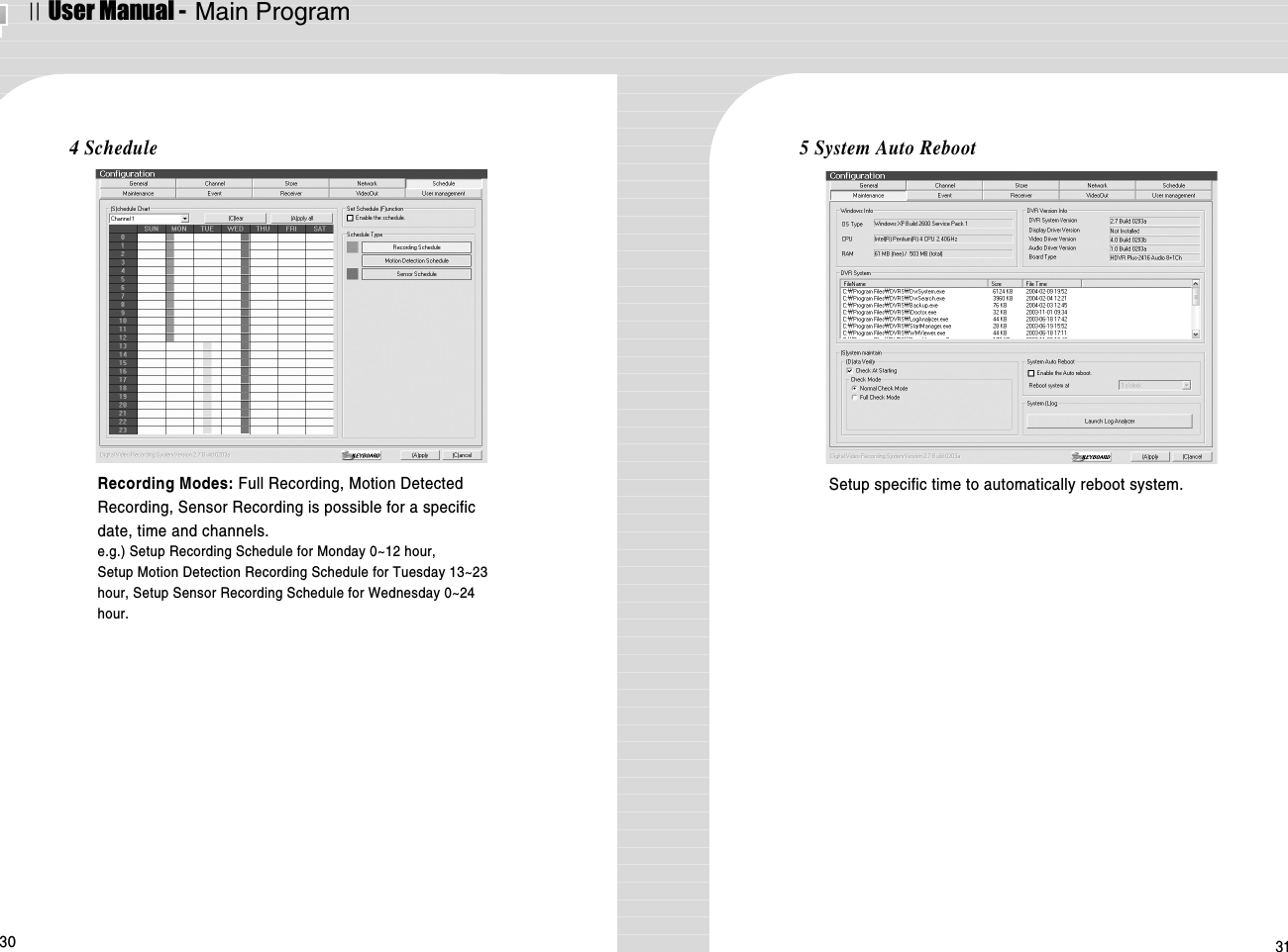
![ⅡUser Manual - Main Program32 336 Event※※Sensor Input- Check [Enable the Sensor] and configure the channelof camera and sensor input channel.※※Enable Event Recording- Use Digital Output OR auto-recording when there issensor input signal. e.g.) Configure 1,2,3,4 Sensor Input for CH1 Camera & 5,6,7,8Digital Output. Enable Event Recording & Warning Sound fromspeaker.※※Motion Detection Motion Detection Area Setup, Motion DetectionSensitivity SetupSetup MD Area: Setup rectangular area in screenusing the mouse.Motion Display: Indicate the specific area bychanging color when motion is detected.Motion Recording: Record when there is movementin image7 Receiver※Port Setup: Select serial port to use PAN/TILT Camera OR Receiver.※Device Type: Select protocol of receiver from Device Type Panel. 8 Video OutVideo Out function can be used by Loop-Through to analog monitor. ※※Enable the TvOut Rotation :One channel can be viewed during the directed time gap orvarious selected channels can be viewed in timed sequence.※※Single Mode : Only the selected one channel is viewed](https://usermanual.wiki/INTO-TECH/SPLUS.users-manual-1/User-Guide-532349-Page-16.png)
![ⅡUser Manual - Search Program34 359 User ManagementUser Managemet can give different authorization levelsfor management in accord to user IDs.※※Insert & Modify User InformationInsert ID & Password and click [Modify User Information] icon to add new user.※※Accessible local FunctionsFunction to manage DVR System in installation site–Support setup for all the functions of DVR.※※Accessible Network FunctionsSetup of only limited function is available for usersconnecting from outside using client program※※Accessible ChannelsDirect only certain channels to be viewed according touser IDs.1-1 Control Panel02.Search ProgramSearch Program allows users to search by time/date & play recordedimages and audio. Support saving of still image by .bmp format,printing of still image, watermarked .bmp file of each image. Save Icon →Print Icon Serveillance ModeIconWatermarkViewer IconLoad Data Icon- Surveillance Mode Icon: Exit search program andconverts to Survillance Mode(Main Program). - Load Data Icon: Open Calendar for loading data.](https://usermanual.wiki/INTO-TECH/SPLUS.users-manual-1/User-Guide-532349-Page-17.png)
![ⅡUser Manual - Search Program36 37CalendarMD ONLY Icon: Load Motion Detected data only.LOAD Icon: Load data of selected date from calendar.- Save Icon: Save image of selected channels- Print Icon: Print image of selected channels using printer. Print Channel: Select channel for printing images.Option: Print image with caption OR goto printer setup.Print Type: Setup print layoutWatermark Viewer Icon: Run Watermark Viewer.Watermark Viewer Open saved .bmp file to check if there is any image tampering &check if watermark is identical with original image. 1-2 Playback Control PanelSupports playbackoptions: 1x, 4xplayback, reverseplayback, frame byframe playback.[Playback Control Panel] [Screen Partition Panel]1-3 Screen Partition PanelSupport 8 kinds ofvarious screen partitiondisplay.1-4 Data Search Process Bar - Hour Button: Recorded data of selected hour is indicated in red color.- Minute Bar: Minute of recorded data is indicated 0~59min. andrecorded data is indicated in red color.1-5 Search Audio Volume Control BarControl audio volume when replay of recorded data.Hour Button ←←Minute Bar ←←](https://usermanual.wiki/INTO-TECH/SPLUS.users-manual-1/User-Guide-532349-Page-18.png)