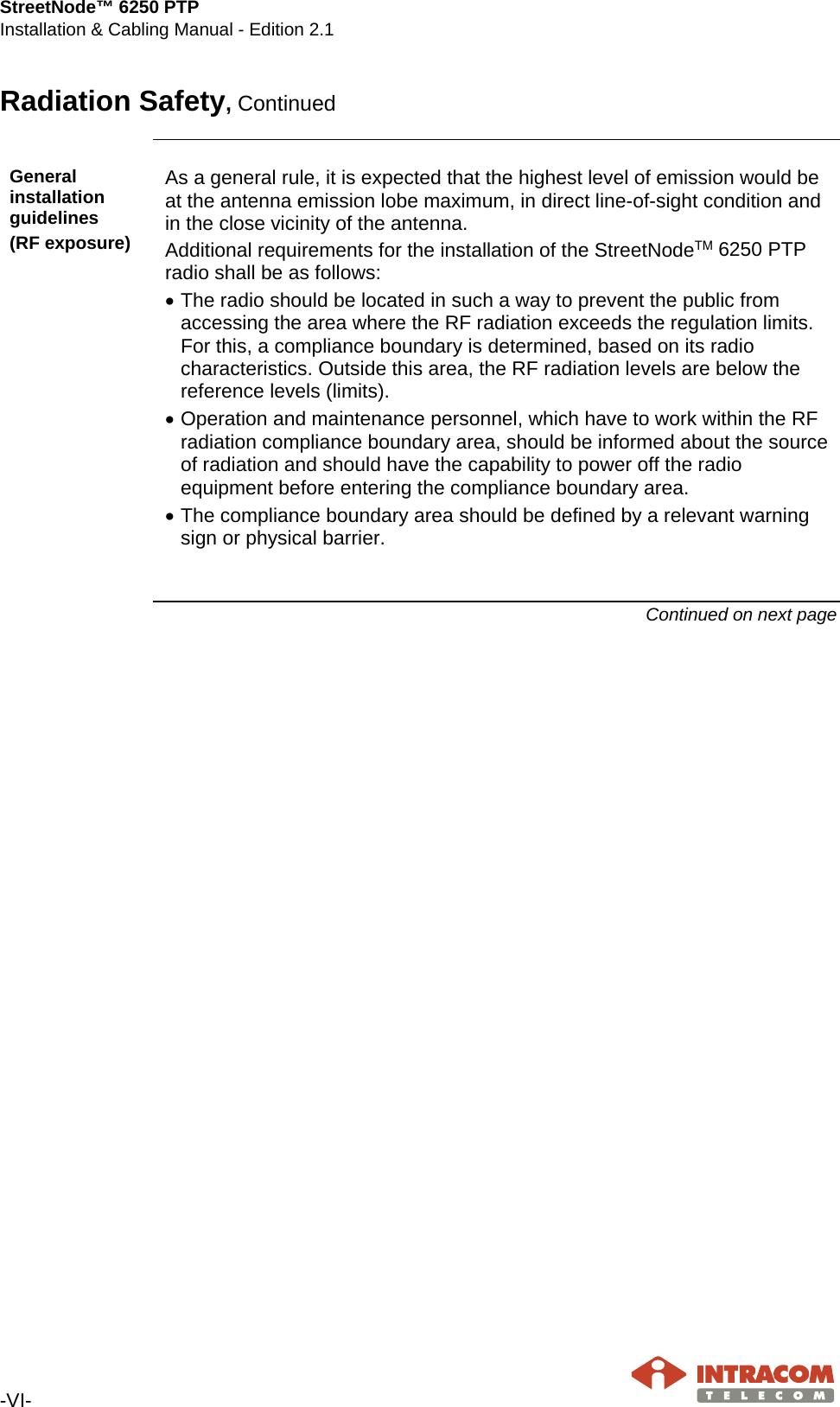
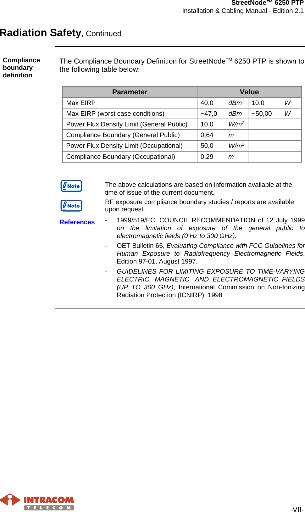
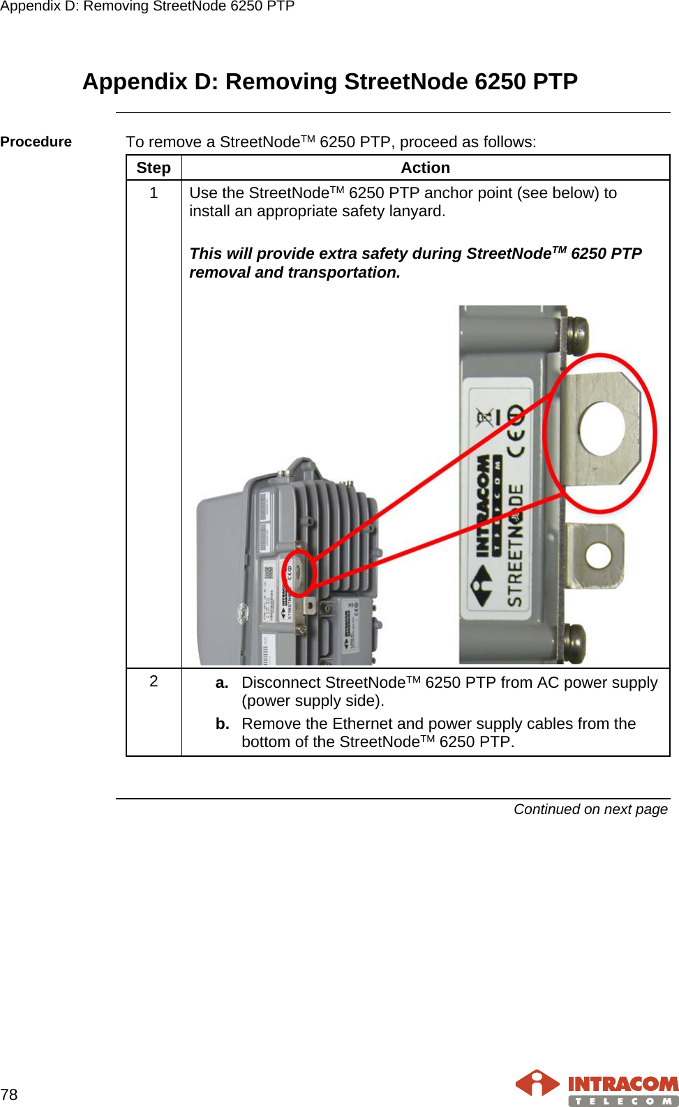
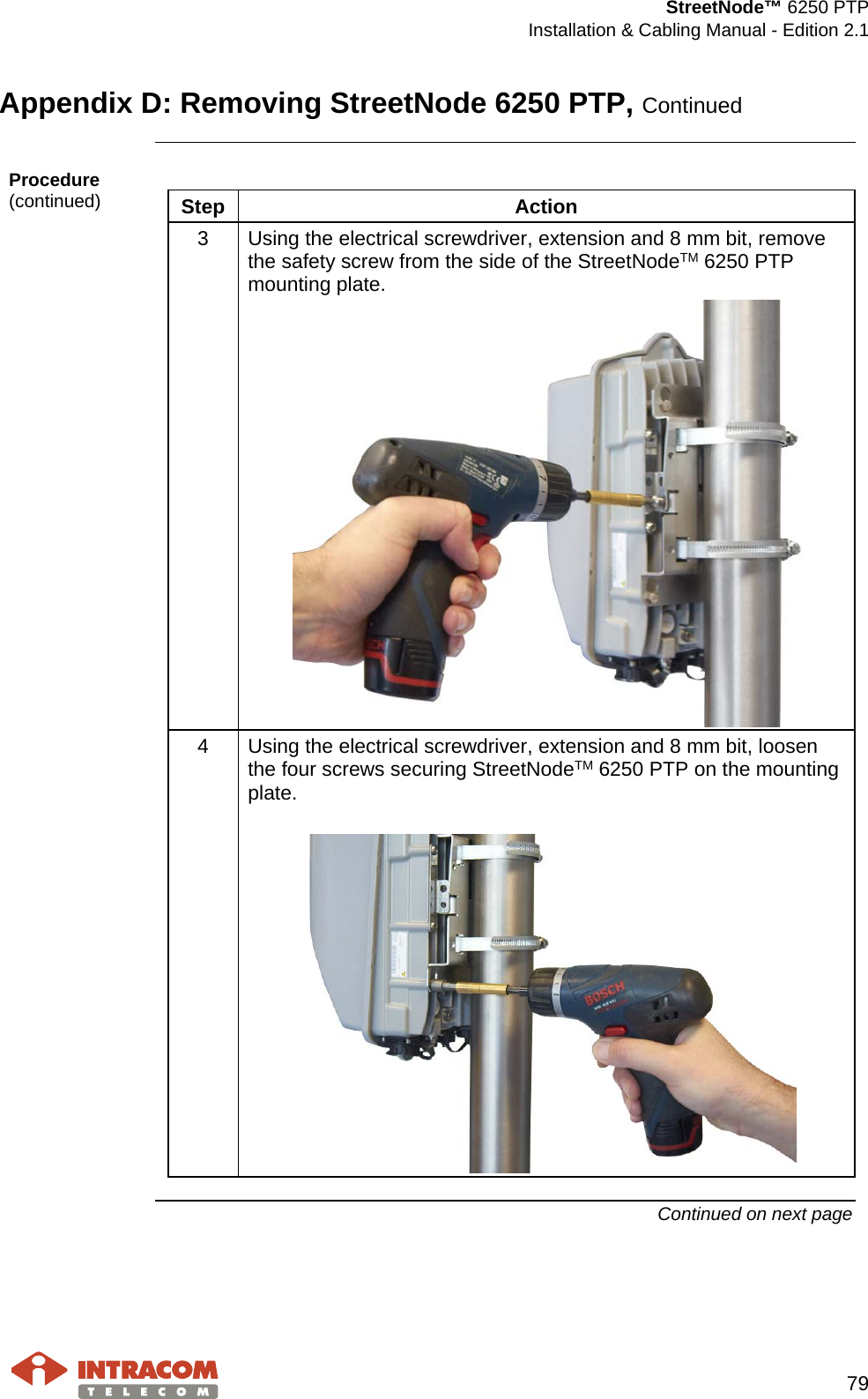
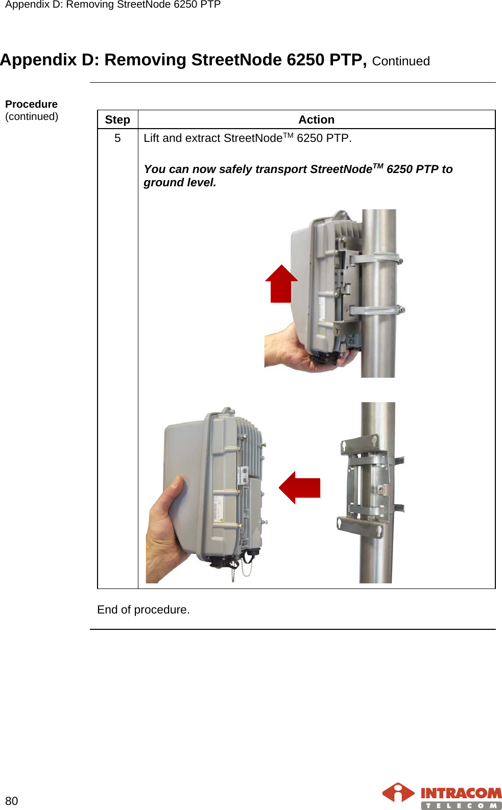
INTRACOM TELECOM SOLUTIONS SN6250F12HW16 Point-to-Point Gigabit Radio 60 GHz User Manual StreetNode 6250 PTP
INTRACOM S.A. TELECOM SOLUTIONS Point-to-Point Gigabit Radio 60 GHz StreetNode 6250 PTP
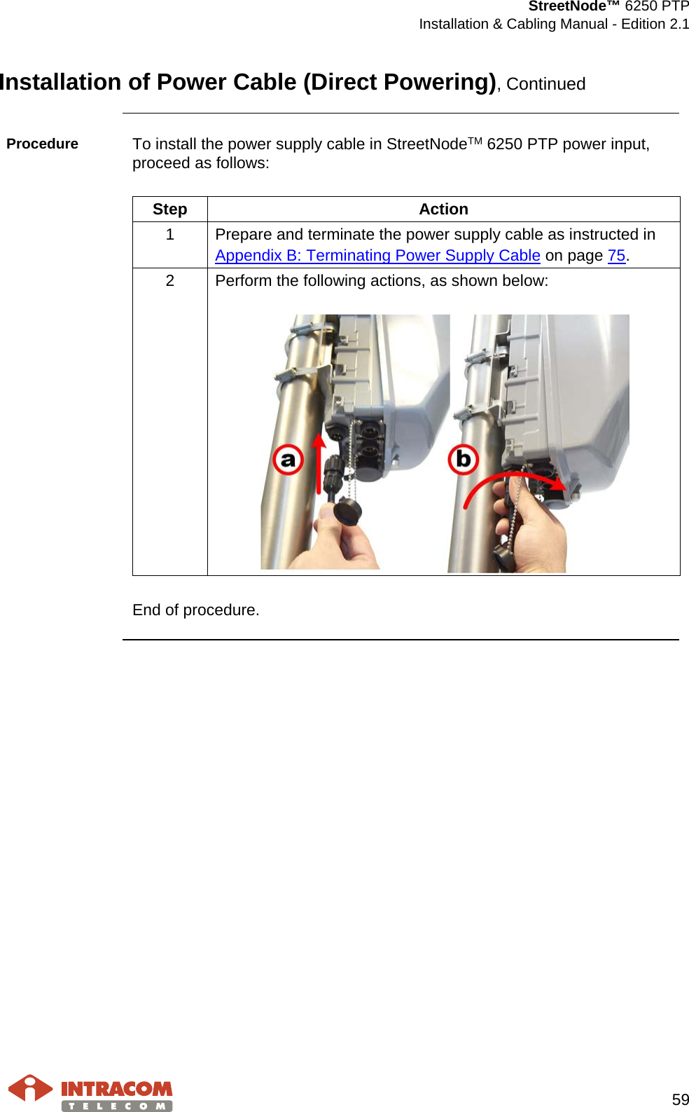
Contents
- 1. Installation manual
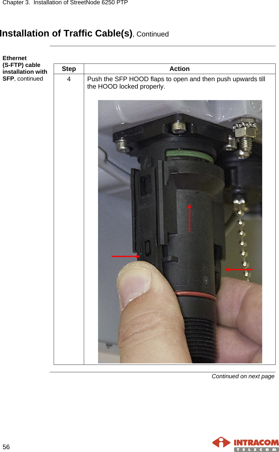
- 2. Commissioning Manual
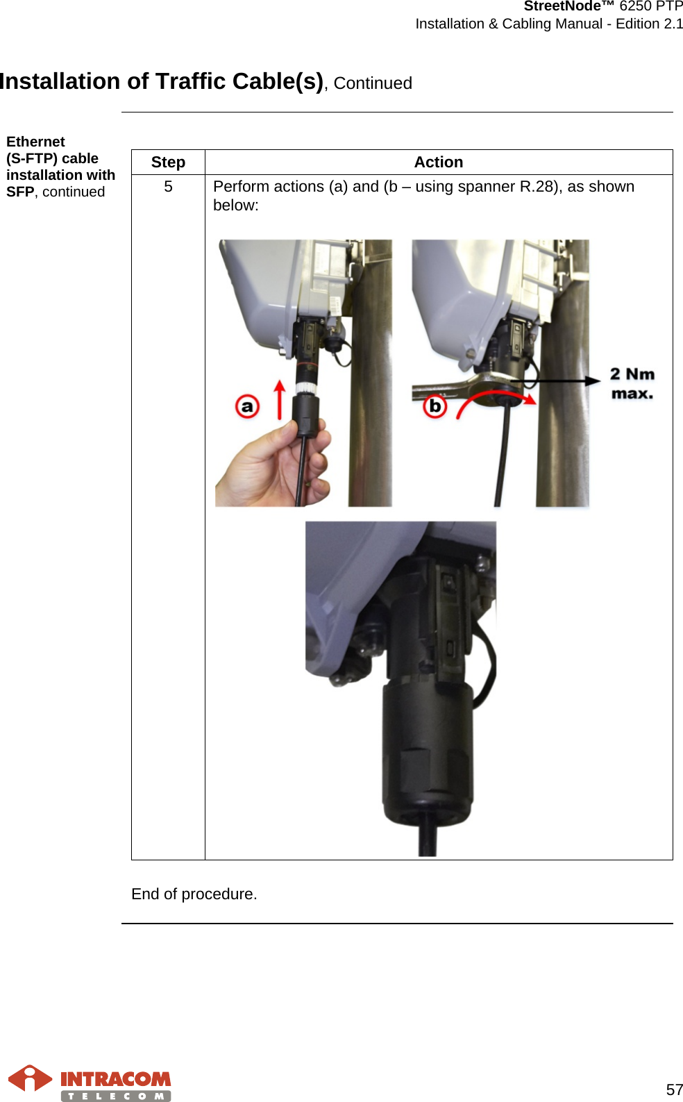
Installation manual