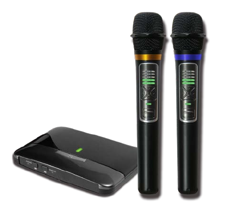
INVENTEC BESTA CA913 Digital Wireless Receiver User Manual Pro
INVENTEC BESTA CO.,LTD Digital Wireless Receiver Pro
Users Manual

DMR-101 &DMT-101
(
BESTA
)
User’s Manual
Main Features
This is the first microphone created with 2.4G Digital Wireless Technology, avoiding interferences issues
stipulated in wireless microphone that you can enjoy high-quality sounds now.
First innovative 2.4G Digital Wireless Technology in Industry is featured with its high-speed
transmission and 60m linear reception; it used for no-harassment in management of channels with audio
quality in perfection rendered!
2.4G Technology is featured on its extremes of energy saving; it use of alkaline battery (1.5V AA x2) that
is endurable more than 30 hours successively.
The exterior streamlined design, in line with visible pearl black paint and further thermal UV treatment, is
free of paint falling everlastingly which highlights its high quality.
The dustproof cover, made of high-stiffness of steel, presents higher level of protective effects from
extremely precise electroplating treatment and coating on the surface; the closely integrated design in the
microphone and dustproof cover is excellent in drop and shock resistance which significantly reduces extra
sound generated from shakes.
Volume Adjuster is uniquely attached that + - buttons on the microphone enables to adjust volume
remotely with ease.
The ultra-thin design of mini receiver at 200g enables you to hand carry in convenience or include it into
decoration at home simply or use with a power bank outdoors.
The set is equipped with thick, solid bass and clear pitches that highly sensitive microphone component
enables presentation of genuine human voice which is applicable to multiple purposes such as singing,
giving speech, conference and teaching.
Within echo sounds effects perfectly sing in Karaoke.
Need not to connect an audio mixer, background music and microphone sound mix down automatically.

Digital Wireless Receiver
I. Parts of Introduction
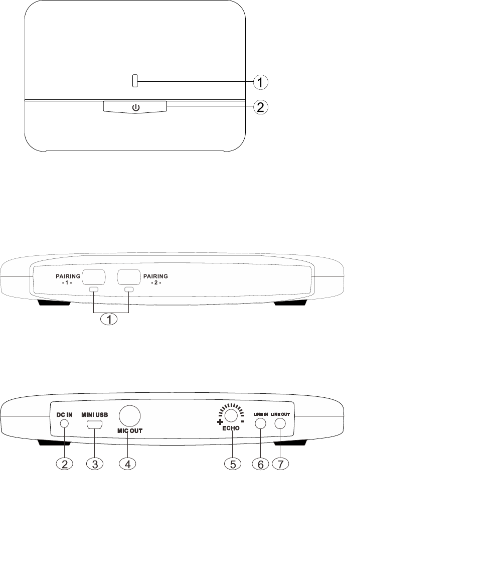
Up Side
1. Light of Power ON/OFF:Green light is on when it is powered on, standby is red.
2. Power ON:Press &hold for 2 seconds (light from red to green) to turn on the receiver.
Power OFF:Press &hold for 3 seconds (light from green to red) to turn off the receiver.
Front Side
1. Match Button on Microphone(MIC1、MIC2): It is used for match between microphone and receiver.
Back Side
2. DC In: Connect Power Supply and Input power at 5V (DC).
3. MINI USB: Connect to PC/ Notebook, as the switch of previous/next page in presentation mode
4. Audio Output (MIC): ψ6.3mm audio output hole connects receiver to power amplifier (mixer)
5. Echo Control: Echo effects control
6. LINE In: Connects to background music or Karaoke music
7. LINE Out: Connect 3.5mm cable or connect to powered speaker through composite video connector
II. Installation and Operation of Receiver:
1. Connection of Power Input:
Connect input side of 5V(DC)Power Supply to power input hole and connect the other side to AC Power
Outlet.
(▲Note:AC Power spec of POWER SUPPLY must fit with voltage range locally.)

2. Connection of Audio Output (A):
Connect double ψ6.3mm Plug to Audio Output Hole of Receiver(MIC) and connect the other plug to Power
Amplifier or other input surfaces of mixer (MIC IN).
(▲Note:Please connect both sides of double ψ6.3mm Plug well, then, power on Power Amplifier or other
machines with audio input, such as mixer. It is to avoid any temporary sound of contact while in
connection between machines such as Power Amplifier or Mixer and double ψ6.3mm Plug.)
3. Connection of Audio Output (B):Connects to LINE OUT hole by powered speaker through composite video
connector or 3.5mm cable
4. Power on and activate the receiver; green light is on.
Digital Wireless Microphone
I. Parts of Introduction
1. Head of Microphone.
2. Volume Light:5 degrees of volume control, light more means volume up.
3. Volume Key-:Press it to decrease the volume of microphone;
Volume Key+:Press it to increase the volume of microphone.
4. LED indicator:Green is on while it is powered on; Red is on means to replace it
with new batteries.
5. Power Switch:Push ON/OFF switches.
6. Left/ Right Key:By Karaoke to raise/lower key or as the switch of previous/next
page in power point mode with dongle
II. Battery Installation
1. As shown on above chart:
Rotate bottom side of microphone counterclockwise until the sleeve is removed.
2. Please put into 2 batteries (1.5V AA Alkaline Battery) correctly into the battery compartment that negative
pole is toward the microphone head.
3. Rotate the bottom side of microphone back clockwise once Item 2 is done.
4. The batteries shall be removed if not use microphone for a long time, avoiding damages of springs and
circuit inside arisen out of battery fluid flowed.
5. Match Key(above the battery):It is used for match between microphone and receiver (It is default paired
already).

III. Operation
Frequency of receiver and microphone has been matched while in delivery, please operate as follows:
1. Power on the microphone by Power Switch. At this time, the green light is on. At the mean time, volume
light of receiver is on, referring to volume of microphone.
(Note:If the pairing light is off, means receiver and microphone is not match which needs to be
done anew.)
2. Please operate as follows for matching microphone anew if necessary:
a. Power on the receiver and microphone; remove bottom sleeve of microphone.
b. Press match key of microphone and power light is flashing, then press match keys of receiver (MIC1 or
MIC2) that the receiver is entering into status of searching frequency now. When the pairing light of
receiver is on, means they are matched.
c. Under normal situation, the above matching should be done within 15 seconds. If not, the flashing will turn
off automatically.
█
Precaution
1. The most microphone systems recommended in use simultaneously is at 2 sets to avoid interferences.
2. Do not use and store it in thermal, humid places with dust and place it apart from child
below 3 years.
3. Do not drop it down and collide by force to avoid damages of interior circuit board.
4. If it is dirt, wipe it with soft cloth; organic solvent classified as chemical product is prohibited.
█
Specification
█
Trouble Shooting
Why do I install the devices correctly but not working?
1. Make sure microphone's battery loaded and enough power to operate.
Make sure the power light of receiver is green.
2. If the pairing light is off, means receiver and microphone is not matched which needs to be done anew.
3. Make sure use specific cables for our devices only.
4. None above. Contact your customer service.
Operation Frequency Bandwidth 2403MHz~2478 MHz
Frequency channel 26 CH
Carrier Spacing 3 MHz
Modulation GFSK
Transmitting rate 3 Mbps RF data rate
Antenna type PIFA antenna
Sampling rate 48 KHz/ 16 bit
Sensitivity S/N -84dB (A-weighted)
Dynamic Range > -82 dB (linear Max S/N)
Frequency response 20Hz~20KHz
Distortion < 1 %
Latency < 10 ms
Distance >20m
Federal Communication Commission Interference Statement
This equipment has been tested and found to comply with the limits for a Class B digital device, pursuant to
Part 15 of the FCC Rules. These limits are designed to provide reasonable protection against harmful
interference in a residential installation.
This equipment generates, uses and can radiate radio frequency energy and, if not installed and used in
accordance with the instructions, may cause harmful interference to radio communications. However, there is
no guarantee that interference will not occur in a particular installation. If this equipment does cause harmful
interference to radio or television reception, which can be determined by turning the equipment off and on, the
user is encouraged to try to correct the interference by one of the following measures:
. Reorient or relocate the receiving antenna.
. Increase the separation between the equipment and receiver.
. Connect the equipment into an outlet on a circuit different from that to which the receiver is connected.
. Consult the dealer or an experienced radio/TV technician for help.
FCC Caution: To assure continued compliance, any changes or modifications not expressly approved by the
party responsible for compliance could void the user's authority to operate this equipment. (Example - use only
shielded interface cables when connecting to computer or peripheral devices).
FCC Radiation Exposure Statement
This transmitter must not be co-located or operating in conjunction with any other antenna or transmitter.The
antenna(s) used for this transmitter must be installed to provide a separation distance of at least 20 cm from all persons.
This device complies with Part 15 of the FCC Rules. Operation is subject to the following two conditions:
(1) This device may not cause harmful interference, and (2) This device must accept any interference received,
including interference that may cause undesired operation.
Inventec Besta Co., Ltd.
10F, No. 36, Lane 513, Rui Guang Rd, Nei Hu Dist.,
Taipei, 114, Taiwan, R.O.C.
© Copyright 2013 by Inventec Besta Company
The information contained herein is subject to change without notice.
Inventec Besta shall not be liable for technical or editorial errors or omissions contained herein.