IP COM NETWORKS AP255US Wireless Access Point User Manual AP255 USV1 0 E01
SHENZHEN IP-COM NETWORKS CO.,LTD. Wireless Access Point AP255 USV1 0 E01
UserManual.wiki
>
IP COM NETWORKS
>
AP255US User Manual
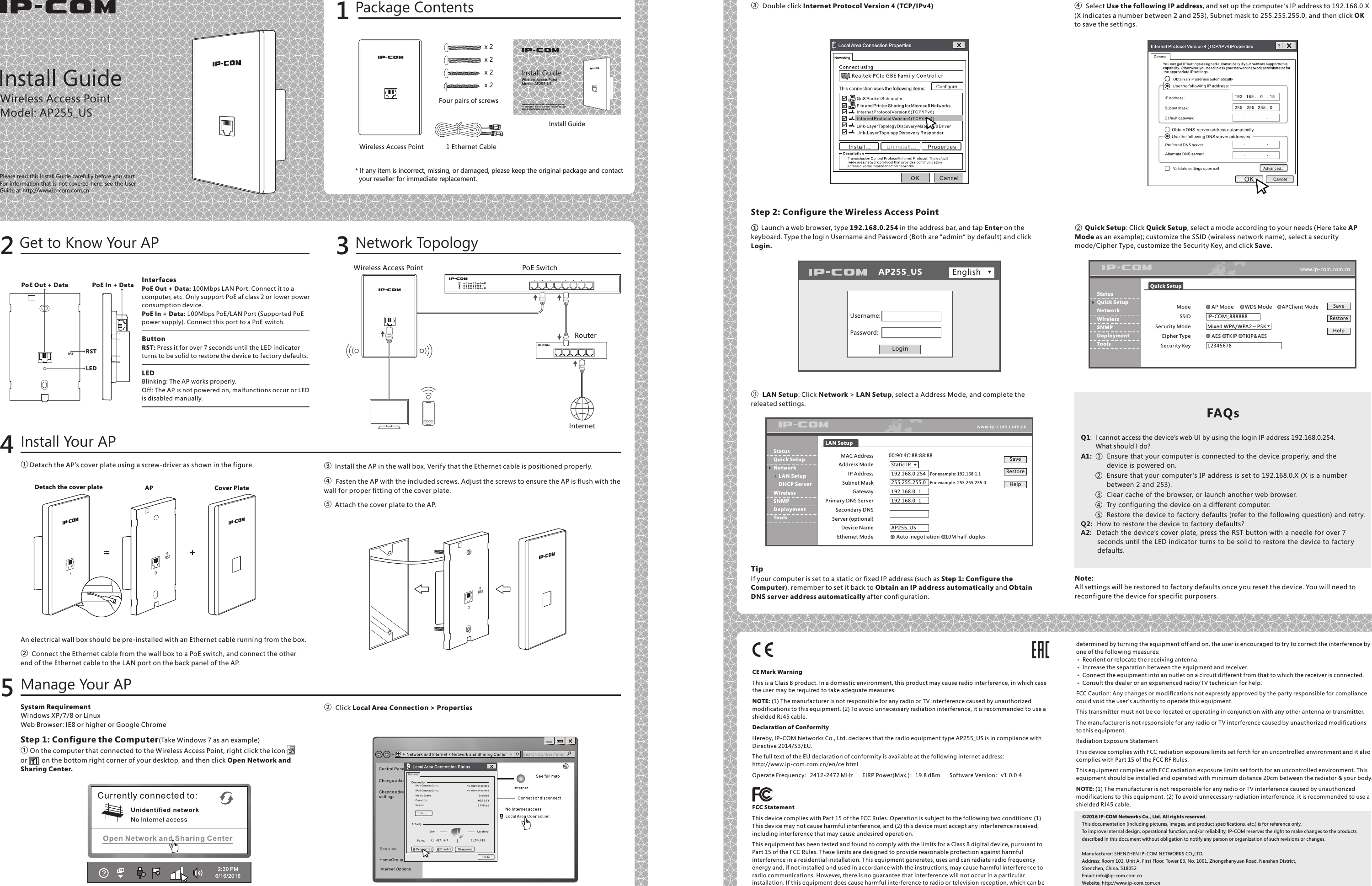
Users Manual
Navigation menu
Upload a User Manual
Namespaces
Wiki Guide
HTML
PDF
Info
Views
User Manual
Discussion / Help
Navigation